

Page 1

Programming the
HP 4145B and
HP
with a PC
4142B
First Edition - July 1992
US Semiconductor Systems Center
Page 2

CONTENTS
1
2
3
4
INTRODUCTION
About this Guide
Configurations
PROGRAM FUNDAMENTALS
Initialize
Capture
Analyze
Sample Programs
DEVICE ADDRESSING WITH THE HP AND NATIONAL CARDS
HP-IB Interface Card
National Instruments PCIIA Interface Card
Differences between the HP and National Cards
PROGRAMMING WITH HP INSTRUMENT BASIC
1-2
1
2
3-6
3-4
6
6
6
7-9
7
8
9
10-11
5
6
7
8
PROGRAMMING WITH MICROSOFT QuickBASIC
PROGRAMMING THE HP 4145B AND HP 4142B
MessageBasics
Three Message Types
HP4145B Programming Hints
HP4142B Programming Hints
DifSerences Between
4146B DATA TO ASCII
SAMPLE PROGRAMMbfING DISK
REFERENCES
Progr
amming the HP4146B & HP4142B
12-14
15-22
16
17
18
19-20
21-22
23-24
25-26
27
Page 3

INTRODUCTION
Today’s research and manufacturing engineers are being pressured to improve productivity while
reducing costs. To remain competitive in the fast-paced electronics marketplace, engineers must reduce
product design cycles. Testing the finished product must be accomplished in the shortest possible time
and in the most repeatable manner. Both of these requirements are causing engineers to rely heavily on
computers to automate the process.
The personal computer is now commonplace on the design engineer’s bench. These powerful machines
feature software packages that allow the novice programmer to quickly analyze devices.
low cost of the personal computer, teamed with the power of custom software, engineers can significantly
speed the development and analysis of their devices.
ABOUT THIS GUIDE
This guide describes how a personal computer can be used to program the HP 4145B Semiconductor
Parameter Analyzer or the HP 4142B Modular DC Source/Monitor via the IEEE 488.2 interface bus.
Many programming fundamentals, examples, and sample programs are provided to get you started and
to help overcome some of the hurdles a first-time programmer faces.
Now with the
There are many different types of computers, software, interface cards, and instrument commands that
we could discuss. However, this guide is not intended to be all inclusive. That is, it is not a tutorial on
HP-IB, programming a personal computer, or the full HP-II3 capability of the instruments. It is intended
to demonstrate the basic concepts of HP-IB communication and provide suf6cient information and
examples to get you started. It is meant to be used with the knowledge contained in the documents listed
in the “Fteferences” Section.
Page 4

- INTRODUCTION -
CONFIGURATIONS
We will use various combinations of the following configurations in this guide and the dish provided.
Although the example programs and the text are based on Instrument BASIC and QuickBASIC, the text
content can be valuable for programming in other languages.
method of passing information to and from the instruments still apply.
The subroutine calls are the same and the
PC:
Software:
IEEE 488.2
interface cards:
NOTE: The contents of this guide are also applicable to the 4146A.
HP Vectra 336 or IBM/AT (compatible) with 4Mb RAM
HP Instrument BASIC for Windows - E22OOA (Rev A.OO.001
Microsoft QuickBASIC (version 4.51
Microsoft Windows (version 3.01
Hewlett-Packard 82335B HP-B3 card (Windows)
National Instruments GPIB-PCBA card
2
Page 5

PROGRAM FUNDAMIZNTALS
In this section we are going to discuss the three fundamental parta of a program.
below may help visualize the three steps.
The program flowchart
PROGRAM FLOWCHART
put In output buffer
INITIALIZE
First, initialize the HP-IB interlace and the instrument This step ensures consistent, repeatable
performance of the program. Without these initiahzation procedures, a program may run one time, but
not function properly the next time. This may be due to some setting change made either from the front
panel or HP-B which may drasticaIly change the conf@uration of the instrument Second, configure the
instrument and set the measurement parameters. You must correctly specify the output channels before
proceeding. Finally, specify the acquisition criteria.
Page 6

-PROGRAMFUNDAMENTALS-
Initializing the HP-IB Interface
CALL IOBESET sets the HP-B3 interface to:
interface timeout = no time limit
interface EOI mode enabled
cr/lf selected as EOL
lf established as the IOMATCH default
CALL IOCLEAR clears the interface by:
terminating any bus communication in progress (UNTalk, UNListen)
clear all serial poll status bits
clear the input and output HP-IB buffers
clear the error queue and key register
stop any measurement or acquisition processes
CALL IOTMEOUT sets an interface timeout value in seconds to handle I/O operations that do not
complete. For example, the HP-B3 cable is not attached or the instrument address is not correct. Once
the HP-IS interface and instrument are initialized, the I/O timeout should be reduced, otherwise the
controller will ‘hang’ if the instrument does not respond. If the instrument does not respond within the
allotted time, the controller will abort the I/O operation and report an error condition. Once again, all
parameters passed to an HP-B3 subroutine are variables. To specify an I/O timeout limit of 10 seconds,
use the following
TIME=10
CALL IOTIMEOUT(ISC,TIME)
Initializing the Instrument
The ‘BST is a common command that resets the HP4142B to a known default configuration.
command will ensure that the instrument is in a known state before configuring it.
command will ensure very consistent, repeatable results. Without the ‘BST, a program may run one
time, but the program may give different results the next time if the instrument is configured differently.
The HP4145B does not have a command to reset the instrument to a known default state. The menus
retain the same values from the previous acquisition unless overwritten.
to specify all setup conditions for each test. The HB4145B boots up with the default configuration.
Specifying the Acquisition
From the front panel of the HP4145B, the acquisition mode is set by pressing the appropriate
measurement key (single, repeat, or append). For the,normal front panel run mode, this is the only
control that needs to be made. When programming the instrument over the bus and using the “MD
command, the acquisition mode is specified by using a 1,2, or 3 respectively.
Therefore, it is very important
Using the ‘BST
Using this
4
Page 7

CAPTURE
At this point the instrument and interface are completely configured. The trigger command can now be
executed. The trigger command clears the data buffers, acquires data for the requested channels to the
specifications that have been set, and finally stops the acquisition process when complete, displaying the
signal on the HP4145B display.
The HP4145B measurement command is “MD”. The HP414!2B measurement command is “XEY.
However, even though the instrument has been properly initialixed and set up, measurements cannot yet
be made. It must be noted that when the instrument is responding to HP-IB commands, it is in an
interrupt mode, and the data acquisition process is being held off. Changes to the instrument’s
configuration invalidate previously collected data. As a result, if a measurement is requested
immediately, there may not be suf6cient data available to analyxe.
the bus to determine the HP4145B response byte. Serial polling is not required with the HP4142B.
Aquired data must first be sent to the output buffer (automatic with HP414!2B) before being transferred
to the computer or internal disk of the HP4145B.
Gee instrument Operation manuals for details)
The 4145B data format is different from the 4142B.
ANALYZE
Therefore, it may be required to poll
Once the data has been captured, analysis can begin. The HP4145B display capabilities allows you to use
markers, lines, and user functions on the front panel. The data can also be transferred from the buffer
and displayed on the computer, saved to the PC disk drive, or printed to an external device. In the
sample programs, a disk 5le is opened, the measured and source data are written to a file, and the file is
closed.
5
Page 8

- PROGRAM FUNDAMENTALS -
SAMPLEPROGRAMS
The sample programs on the disk are written for both the HP 4145B and HP 414!2B using both HP
Instrument BASIC and Microsoft QuickBASIC with the HP-IB and National PCIIA interface cards. The
sample programs follow the format of initialize, capture, and analyze as discussed earlier. The
complexity of the programs range from a simple btier dump to an extensive data output handling
routine. Each program has its own comments written into the program which explain each step. You
tan write your own custom program by selecting and modifying these steps.
Both the HP Instrument BASIC and Microsoft QuickBASIC sample programs contain the following
fundamental information:
HEADER INFO:
INITMUZE:
SEND COAtWANDS:
CAPTURE DATA:
TRANSFER DATA:
ANALYZE DATA:
HANDLE ERRORS:
Define global variables and constants; specify include files; call the
various functions.
Initialize HP-IB interface and the instrument; setup the instrument and
measurement parameters.
Send appropriate programming commands to the instrument.
Perform simple parametric measurements.
Bring data from the instrument buffer into the computer.
Display on the computer, store to a PC disk file, or print to an external device.
Include error checking subroutines to report any errors.
Page 9

DEVICE ADDRESSING WITH THE
HP AND NATIONAL CARDS
HP-IB INTERFACE CARD
The address is composed of two parts:
1. Interface Select Code (IS0
2. Instrument Address
Each interface card has its own ISC address set on the card. This address is used by the subroutine calls
to direct commands and communications to the proper interface. A PC can use multiple interfaces, but
each card must be assigned to a unique ISC. The hardware ISC can be selected, or changed, by using the
switches found on the interface card. Because some address combinations may result in internal
controller bus confhcts, please refer to the installation section of your interface card manual.
Each instrument on the IEEE 433.2 bus also must have a unique address that is between decimal 00 and
30. The instrument address must be set with the bit switches on the back of the HP 4145B and
I-P 4142B as described in their respective Operating manuals.
The factory default values for the ISC address is 7 and the instrument address is 17.
set to 6 in our example programs. Parameters passed to the subroutine calls must be passed as variables.
The reference variable passed to a subroutine call must include not only the device address, but also the
correct interface select code.
DEVICE ADDRESS = (Interface x 100) + Instrument
= (6 x 100) + 17 = 617
I
ADDRESSING
The ISC address is
Page 10

- DE??fCEADDRESSING WTH THE HPAND NATIONAL CARDS -
NATIONAL INSTRUMENTS PCIIA INTERFACE CARD
The address is composed of two parts:
1. Interface Card Number
2. Instrument Address
Up to four interface cards may be instahed that can handIe up to 32 instrument addresses each.
The card
number is set to 0,1,2, or 3 by a switch on the card. The default card number is 0 for one card instahed.
Instrument addresses default to DEVl, DEV2, . . . .
DEV32 unless otherwise specified. These can be
modified by running the IBCONFBXE 6Ie found in the GPIB-PC directory. When using QuickBasic, the
National card defaults to respond to any instrument address from 0 to 15. The HP 4145B and HP 4142B
factory defauit address is 17. Change the instrument address to something 15 or less or edit the
ICONFEXE file to tell the card to respond to the second block of 16 address (16-31).
The following is an example of the GPIB Device Map. Here we see the name “HP4142B” at address 02,
and “HP4145A” at address 07.
National Instruments
GPIB Device Map GPWC212A Ver 20
Use the cursor keys or mouse to select boarddevices
Use PgUp/PgDn for maps of other boards
Use the function keys to select an action
I I
-0DEVl -0DEVl -ODEPi -ODEPi wODEV9 wODEV9 -0Dw13 -0Dw13
-0tWU2E -0tWU2E -ODE6 -ODE6 -0DEVlO -0DEVlO -0DEVl4 -0DEVl4
-0DEv3 -0DEv3
-0DEv4 -0DEv4 -0DEV0 -0DEV0 -0DEvl2 -0DEvl2 -0DEvl6 -0DEvl6
F1:Help FMutoConfig F4fhame F!?Diskonnect F8:Edit F9lEsc:Exit
~OHlWiA ~OHlWiA
~ODEVll ~ODEvll
mODEi% mODEi%
8
Page 11

- DEVCE ADDRESSING WTH THE HPAND NATIONAL CARDS -
DIFFERENCESBETWEENTHEHPANDNATIONAL
INTERFACECARDS
While OUTPUT and ENTER statements are supported on both HP and National cards, there are a few
subtle differences in the operation of the two classes of cards:
Pressing the “Scroll Lock” key or “Stop” on the control pad aborts any active I/O statement using an HP
card. That won’t work with a National card; to deal with this problem, IBASIC sets a default lo-second
timeout for National cards that are not specifically configured with a timeout in the GPIB.INI flle.
This means that you should NEVER set a timeout of 0 in WIBCONF; this can cause your IBASIC
program to hang indefinitely on I/O statements accessing a National card.
Timeouts work differently on HP and National cards. IBASIC allows you to set timeouts from 0.001 to
32.767 seconds; an HP card uses the exact timeout value specified. However, National cards support
only a discrete set of timeout values: lOus, 3ous, lOOus, . . . ,3os, 100s
To deal with this, IBASIC rounds up to the next higher timeout value for National cards; if you specify a
2.01 second timeout for a National card, it is actually set to 3 seconds. The default timeout is, as shown
in the previous section, set in the WIBCONF utility.
Another difference regarding timeouts is that on an HP card, the timeout applies to each byte. On
National cards, the timeout applies to the entire statement, which may result in a timeout if you are
transferring a large number of bytes and your timeout is too short.
IBASIC supports the following HPIB CONTROL and STATUS registers, relative to the FtMB
implementation; those registers supported by HP cards are marked under the “H”, those supported by
National cards are marked under the “N”.
9
Page 12

PROGRAMMING WITH HP
INSTRUMENT BASIC
Instrument BASIC for Windows is a complete programming environment designed to provide
measurement results quickly. It provides built-in tools for instrument I/O, graphics, and reporting. It
goes far beyond simply getting measurements from an instrument. I-BASIC provides ail the capability
needed to create simple to complex test programs.
Header Information
Instrument BASIC has unified I/O; in other words, you can communicate with instruments just as if
they were files.
selector with the ASSIGN keyword. You must include an assign statement before any HP-IB commands
are sent.
When using I-BASIC, the HP card is mapped into select code 7 by default and the National card is
mapped into select code 6. We will use select code 6 and the default instrument address of 17 for all the
example programs. Therefore, the device address is 617. (Refer to the Device Addressing sections for
complete details)
To simplify reading and writing, you assign an I/O path to the instrument’s device
ASSIGN @Hp4146 TO 617
Sending Commands
Instrument BASIC gives you powerful commands like OUTPUT and ENTER to set up and get
measurements.
OUTPUT @Hp414S;-BC
Transferring Data to the PC
Instrument BASIC automaticaIly formats data for numbers, strings, and arrays. Use OUTPUT to ask for
an instrument reading.
OUTPUT @Hp4146;PO ‘IB’”
ENTEFt @Hp4146 USING ‘#,S?D,X’;IbO
Use ENTER to read the value from the instrument.
10
Page 13

- PROGRAhfbfING WITH HP INSTRUMENT BASIC’ -
Storing Data to the PC disk
The default format mode is to read and write tiles in an I-BASIC specific form. To specify a text file, use
the FORMAT ON option.
ASSIGN @File TO ‘Datafile”; FORMAT ON
Handling Errors
Instrument BASIC provides automatic error-checking on all of your code, including I/O commands.
don’t have to worry about hanging up the interfAce and computer. You can also click on the handy
“STOP” button to cancel a program at any time.
To prevent other errors from unexpectedly stopping execution, trap the errors and handle them in your
program. I-BASIC provides many simple to use keywords for error handling.
You
11
Page 14

PROGRAMMING WITH MICROSOFT
QuickBASIC
Links to MICROSOFT QuickBASIC Libraries
To run programs in Microsoft QuickBASIC, you must first link to various libraries and include fles.
interface card Command Library disks contain an INSTALL program that copies the BASIC Library files
to your system for you. The location of these files will depend on your computer configuration and where
you specify the files to be insklled. Ftefer to your interface manual for details. You must boot QuickBasic
with the QB /L command.
HP
QB /L C:\HPIB\QBHPIB.QLB
QB /L C:\GPIB-PC\QBASIC\QBIB
National
The
Header Information
The header for the programs set up the necessary error status variables, declares some working
variables, contains related COMMON statements and establishes an error handling routine. The
$INCLUDE statement links in setup conditions for the interface cards. Your program will not respond to
any commands without this line of code.
HP
REM $INCLUDE: ‘QBSETUP.BAS
BEM $INCLUDE: ‘QBDECL.BAS’
National
A variable name is used for the instrument address.
variables. The dev variable must be defined as long to be used as the instrument address with the HP-IB
card. The IBFIND statement is the method used to setup the address of the instrument using the
National card. It reads information defined in the ICONFEXE file. The following example uses the
name ‘HP414!2B’ which was previously setup in ICONFEXE. The name must be spelled exactly as
specikl, including the same upper or lower case letters. The dev% can be any arbitrary integer variable
and does not have to be initialized. (See the Device Addressing section for more details)
HP
DIM SHARED dev AS LONG
dev = 617
It is necessary to properly dimension any shared
National
DIMSHAREDdev%
CALL IBFIND(“HP414!W, dev%l
12
Page 15

- PROGRtWMING WTH MICROSOFT QuidcBASIC -
Sending Commands
To simplify the format of the sample programs when sending messages to the instrument, a generic
output statement has been written. The use of the CALL statement simply makes the code easier to
read.
It is important to remember when using the National card to be sure to include a Iinefeed character
CHIWlO) to terminate commands sent to the instrument. This is a major difference between using the
NationaI and HP library commands. The HP card does not require the Iinefeed character.
HP
DECLARE SUB hp4145 (code$I
CALL hp4145CBC”I
SUB hp4145 (code$)
CALL IOOUTPUTS(dev, code$, LEN(code$))
ENDSUB
National
DECLARE SUB hp4145 (code$)
CALL hp414WBC”)
SUB hp4145 (code8
CALL, IBWRT(dev%, code$ + CHRs(lO))
ENDSUB
Transferring Data to the PC
HP
max.len% = 800: actuaLlen% = 0
data$ = SPACE$Wax.len%)
CALL IOENTEWdev, data& maxJen%, actuaLlen%) CALL IBFUXdev%, data@
National
max.len% = 800
data$ = SPACE$bax.len%)
Storing Data to the PC disk
The following comman d can be used with the HP-IB interface card for storing the captured data to the
PC disk drive. Refer to National’s manual for the equivalent command.
OPEN “Datapm”
FOR
OUTPUT AS Yl
13
Page 16

- PROGRAikiWING WTHMICROSOFT QuickBASIC -
Handing Errors
Errors may occur while communicating over the bus.
is recommended that an error handling procedure be used to report the errors,
An error handling routine is included with QBSETUP.BAS. If a subroutine detects an error, the error
number is placed into the variable called “PCII3.EB.B.” A text error message is placed into the variable
called “PCIB.EBB$.” Your program can examine PCIB.EBB to find the error number and the string
PCIB.EFt.R$ to find the error message text.
After each subroutine call, if the value of the variable PCIl3.EB.B is zero, no error conditions have been
detected. However, if its value is not zero, then the error message can be printed by transferring control,
via the BASIC error trapping facilities, to an error handling routine in the QBSETUP.BAS !Be.
control transfer looks like:
IF PCIB.EBB< >NOEBB THEN PRINT PCIBEIW
It is important to know that the variables PCIB.EBB, PClB.BASEBB, and NOEBB are specified as
COMMON in QBSETUP.BAS.
are recognized.
subprogram environment and must be specified as SHARED variables in any subprogram where they
are used.
For simplifkation, the error detecting/reporting routine is not included in every example program. If
you plan to include any of these examples in your own programs, be sure to add the appropriate error
detecting/reporting. Once program development is complete, some of the error checks can be safely
eliminated.
However, if using subprograms (as in the sample programs), they will not be part of the
This means that in the main program or any functions, these variables
To avoid hanging up the interface and computer, it
This
14
Page 17

PROGRAMMING THE 4145B & 4142B
As we discussed in the “Program Fundamentals” section, there are typically three basic functions that an
engineer will want a computer and a HP
1. set up the instrument
2. make measurements
3. retreive setup information and measurement results for analysis by the computer
Of course, this is not the limit of flexibility of a controller and the instruments, but other more
complicated tasks are accomplished with a combination of these three basic functions.
Since programming the HP 4145B is quite different from the HP 4142B, we will indicate which model is
applicable for the examples.
understand how to make the measurement using the front panel. The HP 4142B does not have front
panel programming capability.
Many front panel and programming operations are similinr
Front panel: push a key, use the menus
Programming send a command, use the subsystems
To be successful in merging the HP 4145B and computer, you first need to
4145B
or HP 4142B to do in a programming environment:
Several front panel and programming operations are different:
Front panel:
Programming
Computers communicate with instruments by sending and receiving messages over the bus using
input/output (I/O) statements provided in the programming language.
Messages
program statements. Each message consists of a device address, a program message, and a terminator.
The address uniqueIy identities one of the instruments on the bus while the program message specifies
the action to be taken by that instrument
for programming the instruments appear as ASCII character strings embedded inside I/O
set value/div, choose graphics display
send the full scale range, get data that can be plotted
on computer screen or converted to engineering units
16
Page 18

- PROGRAhiSfING THE HP 4145B & HP 4142B -
Message Basics: Command/Query
There are two basic forms of messages: commands and queries. The format of the command and query
are the same, but the query usually has a question mark (?I attached to the message.
command and query are vastly different.
> Commands are used to set up the instrument or to specify that an action be taken.
> Queries are used to find out how the instrument is set up or to get results.
The function of the
A query causes the instrument to put data into the output buffer of the instrument.
read from the instrument into the computer using an input statement.
instrument, and a new command or query is sent to the instrument, the error message “QUERY
INTERRUPTED” is displayed.
Message Syntax
To program the HP 4145B or HP 4142B via the IEEE 488.2 bus, you must have some understanding of
the message format and structure expected by both instruments. A complete set of rules is contained in
the programming section of the HP 4145B Operation manual and the HP-B3 Comman d Reference
manual for the HP 4142B.
The basic difference between the two instruments is that the HP 4145B uses a hierarchical programming
structure and the HP 4142B uses low level programming.
4145B: “<Dire&Page> <message><parameters>”
4142B: “<message> <parameters>”
Examples of Commaxlds:
4145B/4142B: BC
If the data is not read from the
This data must be
Clears the output data buffer that stores measurement data and query command response data.
4145B:
4142B:
Example9 of Queries:
4145B:
4142B:
4142B: ERR? Transfers error codes from the error register to the ouput data buffer.
CA1
CA4
ID Puts the revision+ of the
.IDN? Bequests the instrument model number and the ROM version number, and
Set auto calibration ON.
Performs self-calibration on the module in slot# 4.
ROM
and Operating System in the output buffer
stores the results in the output data buffer.
16
Page 19
- PROGRAMMING THE HP 4145B & HP 4142B
-
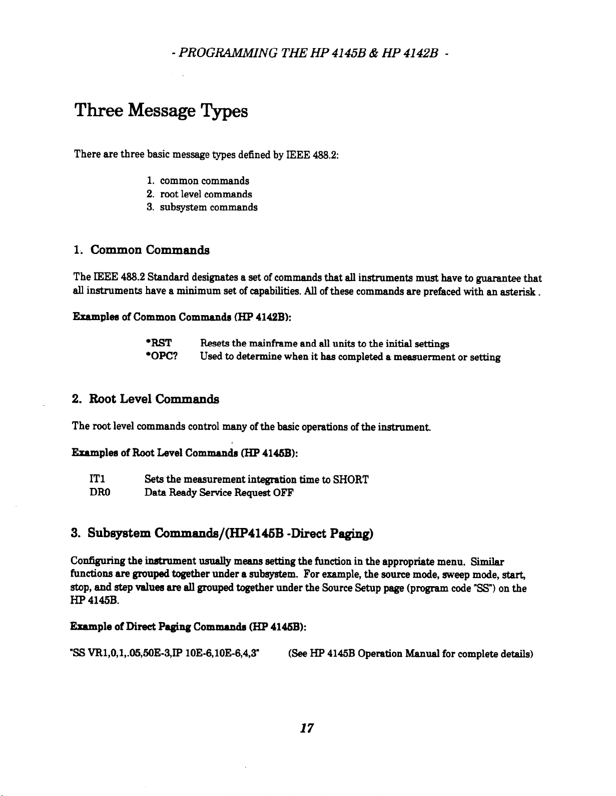
Three Message Types
There are three basic message types defined by IEEE 488.2:
1. common commands
2. root level commands
3. subsystem commands
1. common commands
The IEEE 488.2 Standard designates a set of commands that all instruments must have to guarantee that
all instruments have a minimum set of capabilities. All of these commands are prefaced with an asterisk.
Examples of Common Commands (HP 4142B):
.BST Resets the mainframe and all units to the initial settings
.OPC? Used to determine when it has completed a measuerment or setting
2.
Root Level Commands
The root level commands control many of the basic operations of the instrument.
Examplea of Boot Level Commands (HP 4146B):
IT1
DRO
Sets the measurement integration time to SHORT
Data Beady Service Request OFF
3. Subsystem Commands/(HP4146B -Direct Paging)
Configuring the inhument usually means setting the
functions are grouped together under a subsystem. For example, the source mode, sweep mode, start,
stop, and step values are all grouped together under the Source Setup page (program code “SW on the
H.P 4145B.
Bumple of Direct Paging Commanda (HP 41&B):
“SS VB1,0,1,.65,56E-3,IP lOE-6,1OE-6,4,3 (See HP 4145B Operation Manual for complete details)
function in the appropriate menu.
Similar
17
Page 20

- PROGRAMMING THE HP 4145B & HP 41428 -
HP 4145B PROGRAMMING HINTS
Program Flow
The 4145B cannot store data in its buffer unless a complete measurement has been made including
setting the channel definition page, source setup page, measurement and display page, and graphics plot
or list page.
1)
Program ah pages and display the data on the 4145 screen.
2) Do a serial poll until bit 0 is set to 1 (Data Ready) and use the ‘DO’ command to get the data from the
display to the 4145 instrument buffer.
3)
Read the data from the buffer. The data will just be the measured results. The 4145B does not store
the corresponding measurement setup values. For this reason, it is usually necessary to read the
results into an array in computer memory. Measurement setup values can be generated from the
user program and a similar array is established. This allows measurement setup and results to be
printed or plotted conveniently from computer memory. Data stored on the HP 4145B disk contains
measurement setup and results.
The programming examples show the raw measured data which can be printed out from the 4145 buffer
(BD), as well as formatted data (FD), where the data has been transferred to arrays in computer memory
for tabular printout.
HP-IB switch
There is a switch on the back of the 4145A/B which determines the output data delimiter. When the bit
switch is set to 1 (CR/U?), it allows the instrument to talk directly to a stripchart recorder bypassing the
HP-LB bus. The settings must be in the factory default HP-IB positions for normal instrument control.
Make sure to cycle the power if you change the switch.
Bit Switch 6 (Data Form Bit) Comma 0
Bit Switch 7 (EOI; End or Identify) EOI on
Page 21

- PROGRAMMING THE HP 4145B & HP 4142B -
HP 4142B PROGRAMMING HINTS
Program Flow
This program flow description lists the major order of events required to generate data for a famiIy of
curves similar to a
1)
Reset the instrument with the l RST command. This assures all HPIB commands default to factory
parameter settings and clears the data buffer.
2) Chose the format of the buffer data with the FMT command. The factory default is ASCII data with
header and measured data (results) only. You can chose to store measurement setup data in the
buffer or you can choose to delete the header.
Hint:
4145
display involving VAIL1 and VAIU sweeps.
It is nice to have the
FOR NEXT loops in program code. The disadvantage is it decreases the data acquisition speed by 2.
Filling the data buffer with redundant measurement setup values for every sweep effectively halves the
throughput. Normally only measured data is stored in the buffer for this reason.
The header can be used to note measurement integrity. A three character header is used to sense if any
problems occurred, such as compliance, oscillation, etc. You may want to use this feature if there is
doubt about flxturing or test conditions of your measurement
3) Choose the channels you will use. This is done with the
relay of the channel so a signal can be applied to the device. No further programming of the channel
is possible until the CN command has been issure.
4)
Set the channel source conditions. An example is using the WV command to set a
step, compliance values.
6)
Setthem
voltage sweep.
easurement mode with the MM command. An example is measuring the current from a
4142
retrieve the measurement setup values since it saves the need to create it with
connect
(CIQ command. It closes the output
sweep start, &,~p,
It might seem that the MM command is reduntant But remember that many channels in the 4142 can
be set to various spot or swept conditions. The Mb!I comman
monitor.
d picks exactly which channels you wish to
19
Page 22
- PROGRAMMING THE HP 4145B & HP 4142B -
6)
Trigger the measurement with the XE command. This command automatically stores the data in
the 4142 buffer with no need to issue a poll command for completion of this task.
7) Turn off the channels being used with the CL command. This opens the output relays to each
channel.
Hint:
Use of the CL command is a safety feature to remove any voltages from the device.
hazards as well as prevent thermal runaway (excessive heating) of the device. The CL command also
turns off the standby power required for the HCU and HVU. This conserves mainframe power.
It can prevent shock
Control Software vs Low Level Programming
To eliminate dealing with the low level programming of the 4142, the factory provides a high level TIS
(test instruction set) which is written in HP BASIC. It is documented in the Control Software Manual for
the 414!2B. If you are working on a big multi-user test shell, you may want to consider writing such
drivers in your preferred PC language. The factory Control Software was designed to run on HP
workstations or the PC co-processor card. But similar driver commands can be easily written in
QuickBasic or C for the PC.
For simple projects, or for programs demanding the absolute top speed, you are better off programming
at the HPIB command level.
20
Page 23
- PROGRAMMING THE HP 4145B & HP 41428 -
DIFFERENCESBETWEENPROGRnAMMINGTHE
HP4145B&HP4142B
HP-IB Command Structure
The
4142
is not programmed in a hierachical command structure like the channel definition, source
setup, measurement setup, and display mode setup of the 4145. The 4142 is programmed at a lower level
which allows the user to streamline the command structure or even create higher level heirachical
command structures. This lower level of HP-IB commands also provides much higher throughput test
capability. It is possible to get data from the 4142 buffer as soon as the measurement is triggered. There
is no need to output the data to the buffer like the 4145.
HP 4142B Enhanced Capability
Another major difference is the expanded capability of the 4142 over the 4145.
measurement modes (spot, staircase sweep, pulsed sweep, quasi-pulse, etc). Measurements can be made
on two swept channels at once or any number of spot channels. In addition, the measurements can be
output in a variety of formats to the buffer.
There are a toml of 10
Decreased User Friendliness of HP 4142B
In order to incorporate all these new HP-IB commands, and to maintain high throughput, some user
friendliness of the 4145 was deleted. For example, there is no concept of primary and secondary sweeps
WAR.1 and VAR!Z) as with the source setup paging in the 4145. The 4142 only handles single sweeps. A
family of curves involving multiple secondary sweeps must be constructed in the program code using a
FOR NEXT loop. This is very easy to do in code.
Increased Speed of HP 4142B
Because the 4142 operates with lower level commands and does not have to support a front panel display
mode, capturing data can be 5 to 10 times faster. In the programming examples of this document, an
effort was made to time stamp measurement capture times. Note the speed increase for the same
measurements made with the HP4142 and HP4145.
21
Page 24
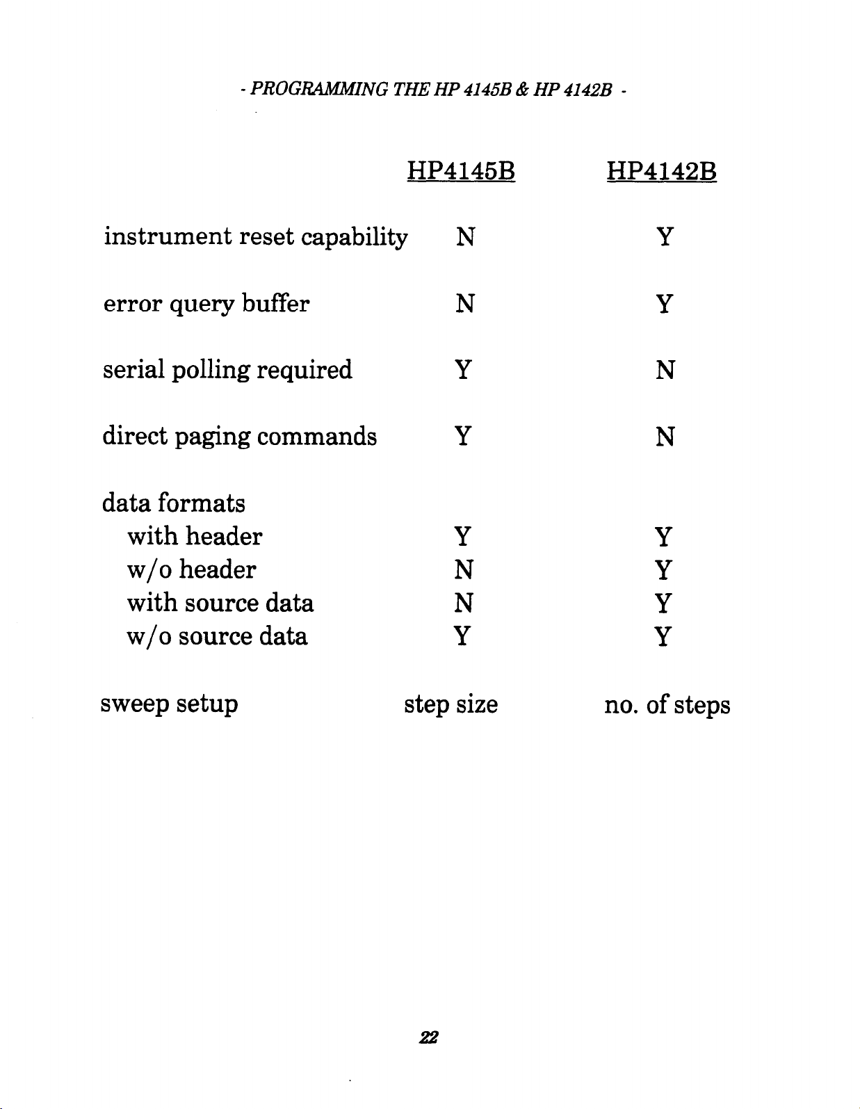
- PROGRAMMING THE HP 4145B & HP 4142B -
instrument reset capability
error query buffer
serial polling required
direct paging commands
data formats
with header
w/o header
HP4145B
N
N
Y
Y
Y
N
HP4142B
Y
Y
N
N
Y
Y
with source data
w/o source data
sweep setup
N
Y
step size
Y
Y
no. of steps
22
Page 25
4145B DATA TO ASCII
One of the nice features of the HP4145B is its built-in disk drive. The HP4145B was originahy designed
for benchtop use. The built-in disk drive provides a means of storing instrument setups and data for
later analysis.
prominent instrument controller. The HP4145B stores data as binary files in a LIF format which is
common to the HP BASIC workstations. Unfortunately, many customers use Analysis software which
require ASCII data. There are three methods to get the 4145B binary data into an ASCII format.
1. Program the 4145B with a PC and store the data to the PC drive.
See sample program IBHPIBDOIBW or 45HPQBDO.BAS
2. Retrieve stored data from the 4145B drive using a PC and re-save it to the PC drive.
See sample program 45DISKIBW
3. Convert the 4145B binary data on the disk to ASCII.
Use LIE Utilities to read the 4145B disk and 45ASCILIBW program to convert the data to ASCII.
The following is is a step-by-step procedure for converting 4145B (BDAT) data files into ASCII for
importing into other anaIysis packages or spreedsheets.
NOTES: The 45ASCIIIBW program only accepts graphics data fiIes (not Iist,schmoo, or matrix data)
The HP4145B was developed in the early 86s before the personal computer became such a
The LIP to DOS file you convert and the 45ASCIIIBW program must reside in the same
directory on your hard disk.
The converted ASCII files are saved on hard disks only.
floppy drive, you wiII get an “out-of-bound” error.
If you try to save ASCII files to the
The 45ASCII.IBW program ia ummppoti and is not guaranteed. You may need to modi@ it to fit
your apeci.fIc needa.
HOW TO TRANSFER FILES FROM 4146A TO 4146B FORMAT
You cannot direct@ read or copy f&s from a 4145A disk with a 4145B or controller.
preform&ted 6 l/4” floppy disks only (16261A) and the record format is not compatible with other
formats such as LIP or DOS. You must use the 16267A File Transfer software to convert the f&s into a
LIF format. This is a simple procedure that only requires a HP4145A, HP4145B, and a HP-E? cable. If it
isn’t possible to use the 4145A and 4145B aide-by-aide, you can use a BASIC controller.
The 4145A uses
23
Page 26
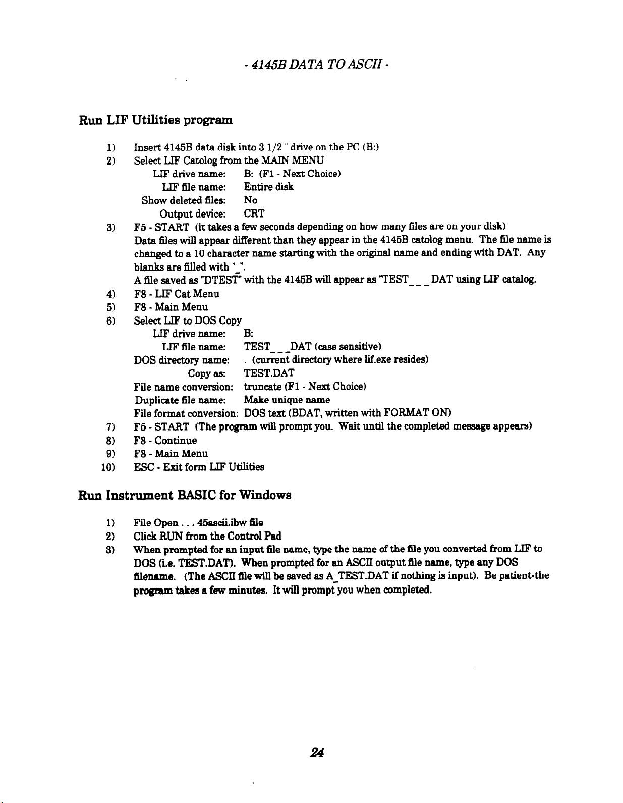
Run LIF Utilities program
Insert 4145B data disk into 3 l/2 ” drive on the PC (B:)
1)
Select LIF Catolog from the MAIN MENU
2)
LIF drive name:
LIF iile name: Entire disk
Show deleted files: No
Output device: CRT
F5 - START (it takes a few seconds depending on how many files are on your disk)
3)
Data files will appear different than they appear in the 4145B catalog menu. The fiIe name is
changed to a 10 character name starting with the original name and ending with DAT. Any
blanks are filled with “,“.
A file saved as “DTEST” with the 4145B wiII appear as “TEST
F8 - LIF Cat Menu
4)
F8 - Main Menu
5)
Select LIF to DOS Copy
6)
LIF drive name: B:
LIF file name:
copy as:
File name conversion: truucate (Fl - Next Choice)
Duplicate fiIe name: Make unique name
File format conversion: DOS text (BDAT, written with FORMAT ON)
F5 - START (The program will prompt you. Wait until the completed message appears)
7)
F8 - Continue
8)
F8 - Main Menu
9)
10)
ESC - Exit form LB? Utilities
- 4145B DATA TO ASCII -
B: (Fl - Next Choice)
---
TEST DAT (case sensitive)
(current directory where Iif.exe resides)
--- DOS directory name: .
TEST.DAT
DAT using LIF catalog.
Run Instrument BASIC for Windows
File Open . . . 45ascii.ibw 6le
1)
Click RUN from the Control Pad
2)
When prompted for an input fle name, type the name of the fiIe you converted from LIF to
3)
DOS (i.e. TEST.DAT). When prompted for an ASCII output file name, type any DOS
filename. (The ASCII fiIe wiB be saved as A-TEST.DAT if nothing is input). Be patient-the
program takes a few minutes. It will prompt you when completed.
Page 27

SAMPLE PROGRAMMING DISK
The sample program disk contains the following three programs using the HP4145B/HP4142B,
HP/National interface cards, and I-BASIC/QuickBASIC. The sample device is a 2N3904 transistor.
BUFFER DUMP (BD)
This program measures the Vbe characteristics of the device. IV data is displayed as unformatted raw
data directly from the instrument’s buffer. This is a very simple starter program which is good for
learning how to initialize the cards and the instruments, make measurements, and retrieve the data.
FORMATTED DATA (FD)
Same as buffer dump program except data is parsed to display the measurement point, Vb, and Ib in a
column. Data in this format is very useful for analysis. It is much simpler formatting the data with
Instrument BASIC than with QuickBASIC. This program also uses a timestamp to show how long it
takes to initialize the cards and the instruments and make the measurements. The HP4142B is much
faster than the HP4145B and the HP card is taster than the National card.
DATA OUTPUT (DO)
This program measures the Vc vs Ic characteristics of the device.
measurement point, the X value (vc), and Y values flc at each lb). The data can be displayed on the
screen, printed to a parallel printer, or stored as an ASCII file. This program also shows how to use error
trapping by automatically aborting instrument control if the HP-IB communication fails.
Graphs of these progxnms would look similar to the followings
Ib
I/
ub
b buffer dup
b formatted data
IO
25
The data is formatted for each
101
I=
uo
.cw..aoutput
xba
Page 28
- SAMPLE PROGRAMMING DISK -
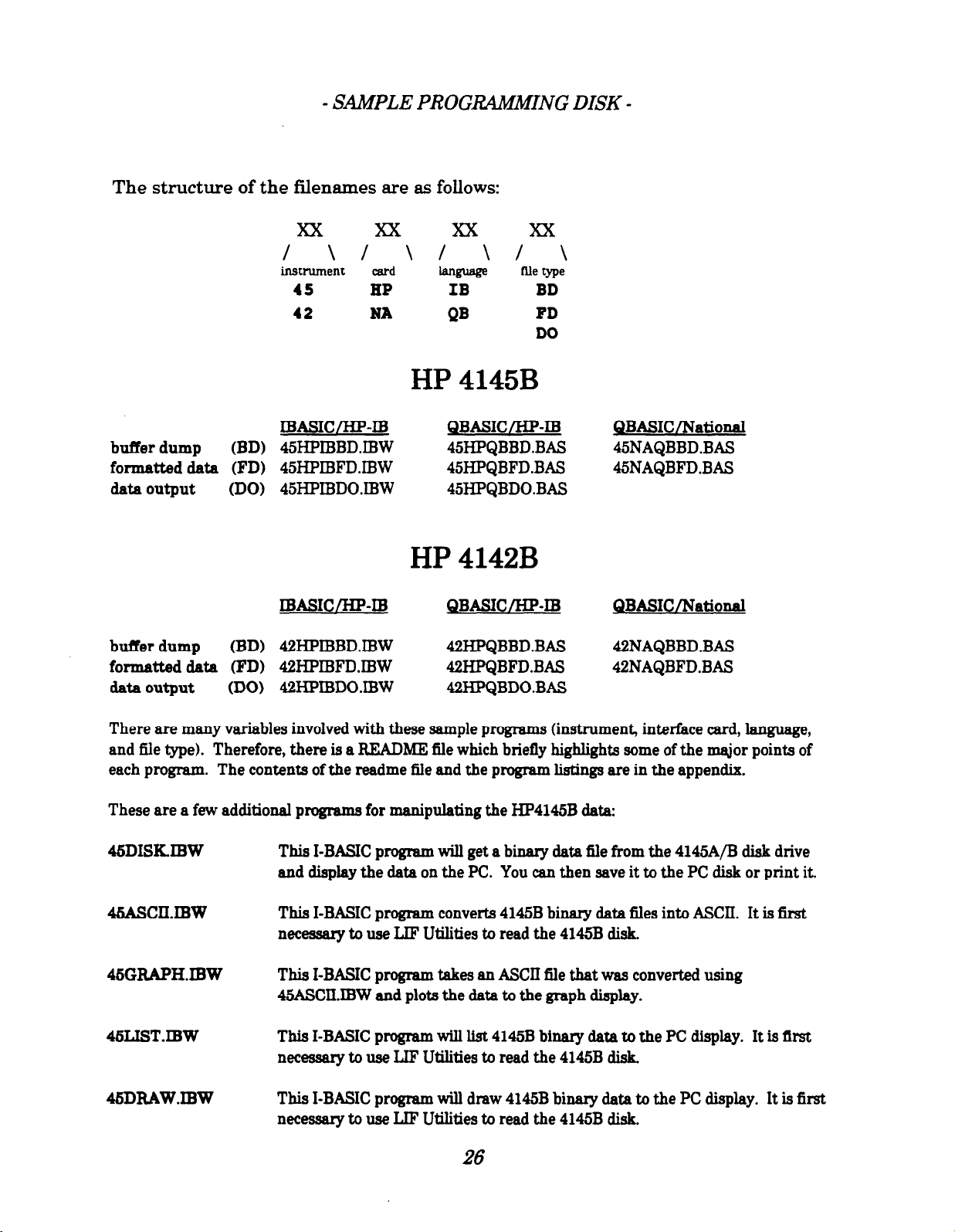
The structure of the filenames are as follows:
xx xx xx xx
I
instrument card
\I \I \/ \
language
45 HP IB BD
42
NA
QB
HP 4145B
file type
FD
DO
IBASWHP-IB
buffer dump (BD) 45HPIBBD.IBW 45HPQBBD.BAS
formatted data (FD) 45HPIBFDJBW 45HPQBFD.BAS
data output (DO) 45HPIBDOIBW 45HPQBDO.BAS
QBA!SIC/HP-III
QBASIC/NationaI
45NAQBBD.BAS
45NAQBFD.BAS
HP 4142B
IBASICLHP-IB QBASIC/HP-ID QBASIC/NationaI
bufk dump (BD) 42HPIBBDIBW
formatted data (FD) 42HPIBFDIBW
data output
There are many variables involved with these sample programs (instrument, interface card, ianguage,
and fiIe type). Therefore, there is a README file which briefly highlights some of the major points of
each program. The contents of the readme fle and the program listings are in the appendix.
These are a few additional programs for manipulating the HP4145B data:
45DISKIBW This I-BASIC program will get a binary data fiIe from the 4145A/B dish drive
(DO) 42HPIBDO.IBW
and display the data on the PC. You can then save it to the PC dish or print it.
42HPQBBD.BAS 42NAQBBD.BAS
42HPQBFD.BAS 42NAQBFD.BAS
42HPQBDO.BAS
45AscII.IBw This I-BASIC program converts 4145B binary data files into ASCII. It is first
necessary to use LIF Utilities to read the 4145B dish.
45GFLAPH.IBW
46LISTJBW This I-BASIC program wih list 41458 binary data to the PC display. It is first
45DRAw.IBw This I-BASIC program will draw 4145B binary data to the PC display. It is first
This I-BASIC program takes an ASCII file that was converted using
45ASCIIIBW and plots the data to the graph display.
necessary to use LIP Utilities to read the 4145B disk.
necessary to use LIF Utilities to read the 4145B dish.
26
Page 29

REFERENCES
The following reference material may be helpful to use during your programming journey. It is especially
important to always reference the product manuals. This guide only covered very basic information from
the appropriate manuals.
HP has a collection of no-charge publications that can help you find solutions to your measurement and
design problems. All free literature is available through your local HP sales office or by calling the HP
Customer Information Center at 899-752-9999 (US only). To receive the publication you want as
quiclky as possible, please reference the publication number found on the back of each piece of literature.
MANUALS
PRODUCT TITLE
4145B
4142B
4142B
4142B
82335B
E22OOA
Operation Manual
Operation Manual
HP-E? Command Reference Manual 94142-99110
Control Software Programming Manual 94142-99210
Using the HP-IB Interface and
Installing and Using HP Instrument BASIC for
FREE LITERATURE
PRODUCT
4145B
4142B
82335B
82335B
E22OOA
E208OA
E22OOA/82335B
823OOC/82324A
Metrics
TITLE PUBX
HP 4145B Semiconductor Parameter Analyzer (Data Sheet)
HP 4142B Modular DC Source/Monitor (Data Sheet)
AN 1219-1: Using
AN 1219-2: Creating Instrument Control Apps w/Viiual Basic
HP Instrument BASIC for Windows Evaluation (3
HP E2989A LIF Utilities for the PC (Data Sheet)
HP Instrument Tools for Winduws (Data Sheet)
HP Measurement Coprocessors for personal computers w/disk
The
Gm~hicai
Difference in Instrument Control & Data Analvsis
l
Co
mmand Library with DOS
Windows E2200-90000
DDE for Test & Measurement
Applications
l/2” disk)
- - -----*---
PARTX
94145-99310
0414290010
82335-90006
5952-7838
5091-1581 E
5991-2959 E
5991-2952 E
5991-2947 EUS
5952-2588
5991-2985 EUS
5091-0240 E
call us ssc
27
Page 30

,
PROGRAM LISTINGS
Page 31

===================
HP 4145 PC programs
===================
45HPQBBD.BAS HP 82335B, QuickBasic 4.5, 4145 buffer dump
------------ ------------------------------------------Call hp4145 is a subroutine which simplifies the syntax for sending GBIB
commands to the HP4145. Notice the LEN(code$). This parameter is necessary
for the HP 82335B card. It keeps track of the length of code sent to the
instrument and can be used to verify transmission.
45NAQBBD.BAS National PCIIA, QuickBasic 4.5, 4145 buffer dump
------------ -----------------------------------------------Call hp4145 is a subroutine which simplifies the syntax for sending GBIB
commands to the HP4145. Notice the CHR$(10). This is a line feed character
which must terminate each line of code. The CHR$(10) is needed for many
HP instruments, though not all.
Format of data from the 4145 is A+DD.DDDE+DD, or 13 total characters for each
number. The first character is a header signifing the nature of the data,
N (normal), C (compliance occurred), etc.
45HPIBBD.IBW HP 82335B, HP Instrument BASIC for Windows, 4145 buffer dump
------------ -----------------------------------------------------------Similar to 45HPQBBD.BAS
45HPQBFD.BAS HP 82335B, QuickBasic 4.5, 4145 formatted data
------------ ---------------------------------------------This routine shows how to read data into an array and then print it in
tabular form. Note 'Call hp4145("SS VR1," ............' This is an example
of how to split long lines of commands into several short lines. The HP
82335 allows passing of parameters without the need to explicitly add ","
as comma delimiters.
Readme.txt
Max. len%=13 is used to read one data point at a time, as Ib vaules. Vb
are calculated with 'vb(i)=str + (i%-1)*(inc)'
45NAQBFD.BAS National PCIIA, QuickBasic 4.5, 4145 formatted data
------------ --------------------------------------------------This routine shows how to read data into an array and then print it in
tabular form. Note 'Call IBWRT(dev%, "SS VR1,".......' This is an example
of how to split a long line of commands into several short lines. The line
feed character is sent only once, at the end of the last segment.
Max.len%=13 is used to read only 13 characters at a time. The header char
is stripped with the RIGHT$(data$, 12) command. The remaining string can
then be converted to a number with VAL(data$).
The 4145 does not record the source data, only measured data. Vb data was
calculated.
45HPIBFD.IBW HP 82335B, HP Instrument BASIC for Windows, 4145 formatted data
------------ --------------------------------------------------------------Similar to 45HPQBFD.BAS
45HPQBDO.BAS HP 82335B, QuickBasic 4.5, 4145 data output
------------ ------------------------------------------This routine shows how to print directly to the screen, printer, or ASCII
file. Error handling has been added to account for HPIB communication
problems (ie incorrect address specified). HP timeout can be set to
automatically terminate communication and prevent locking up the PC if
Page 32

problems occur.
Readme.txt
QuickBasic allows using the PRINT #1 syntax to print to an OPEN screen,
com port, or file. The writing to the file differs only in the formatting of
the data. File data is most useful with comma delimeters, and all other
header or tabbing info removed. File name defaults to DATA.PRN.
Abritrary parameter passing is permitted in this routine, though the screen
and printer outputs are limited to five (Y1...Y5) columns of measured data,
one column of source data, and one column of data numbers (full page width).
45HPIBDO.IBW HP 82335B, HP Instrument Basic for Windows, 4145 data output
------------ -----------------------------------------------------------Same as 45HPQBDO.BAS, except an enhancement has been added to the file writing
routine. Code has been added to prompt the user for a file name and whether
to purge any duplicate file name. I-BASIC does not automatically overwrite
files, as is the case with QuickBasic.
Page 33

===================
HP 4142 PC programs
===================
42NAQBBD.BAS National PCIIA, QuickBasic 4.5, 4142 buffer dump
------------ -----------------------------------------------Call hp4142 is a subroutine which simplifies the syntax for sending GBIB
commands to the HP 4145. Notice the CHR$(10). This is a line feed character
which must terminate each line of code. The CHR$(10) is needed for many
HP instruments, though not all.
Format of data from the 4142 is +DD.DDDDE+DD,+DD.DDDDE+DD, or 26 characters
for measured data, source data pairs when using FMT2,1. FMT2,0 deleters
the source data. You can also add header information with FMT1. Header is
three characters such as NAV (normal, #1 chan, voltage), or CBI (compliance
occurred, #2 chan, current).
FMT1,0 AAA+DD.DDDDE+DD,
FMT1,1 AAA+DD.DDDDE+DD,AAA+DD.DDDDE+DD,
FMT2,0 +DD.DDDDE+DD,
FMT2,1 +DD.DDDDE+DD,+DD.DDDDE+DD,
42HPQBBD.BAS HP 82335B, QuickBasic 4.5, 4142 buffer dump
------------ ------------------------------------------Same as 42NAQBBD.BAS
42NAQBFD.BAS National PCIIA, QuickBasic 4.5, 4142 formatted data
------------ ---------------------------------------------------
Readme.txt
This routine shows how to read data into an array and then print it in
tabular form. FMT2,1 was used to get ASCII data pairs, without header
information. This is the simplest way to retrieve pairs of data.
42HPQBFD.BAS HP 82335B, QuickBasic 4.5, 4142 formatted data
------------ ---------------------------------------------Same as 42NAQBFD.BAS
42HPQBDO.BAS HP 82335B, QuickBasic 4.5, 4142 data output
------------ ------------------------------------------This routine shows how to print directly to the screen, printer, or ASCII
file. Error handling has been added to account for HPIB communication
problems (ie incorrect address specified). HP timeout can be set to
automatically terminate communication and prevent locking up the PC if
problems occur.
QuickBasic allows using the PRINT #1 syntax to print to an OPEN screen,
com port, or file. The writing to the file differs only in the formatting of
the data. File data is most useful with comma delimeters, and all other
header or tabbing info removed. File name defaults to DATA.PRN.
Abritrary parameter passing is permitted in this routine, though the screen
and printer outputs are limited to five (Y1...Y5) columns of measured data,
one column of source data, and one column of data numbers (full page width).
Note the first line in the -----Move data from 4142 to PC-----section.
FOR i% = 1 to VAL(vcsteps$) + 1
The '+1" is needed to try to read an extra data point at the end of each
sweep. This is a way to clear the EOL character from the 4142B buffer when
in QuickBasic. This procedure is not needed when using HP I-BASIC.
Page 34

Readme.txt
42HPIBDO.IBW HP 82335B, HP Instrument Basic for Windows, 4142 data output
------------ -----------------------------------------------------------Same as 45HPQBDO, except an enhancement has been added to the file writing
routine. Code has been added to prompt the user for a file name and whether
to purge any duplicate file name. I-BASIC does not automatically overwrite
files, as is the case with QuickBasic.
Page 35

Module1 - 1 'US Semiconductor Systems Center 45HPQBBD.BAS July 1992 'This MS-DOS QuickBasic 4.5 program uses the HP 82335B HP-IB card with
'the HP 4145B to measure the Vbe characteristics of a 2N3904 transistor.
'It uses the IBRD command to return IV data as an ASCII string array.
DECLARE SUB hp4145 (code$) 'function to send HPIB commands
Dim dev As Long 'variable name for HP 4145B address
Rem $INCLUDE: 'QBSETUP.BAS' 'required by HP 82335B card
dev = 607 'address of HP 4145B
Cls 'clear screen
Call hp4145("IT1 CA1 DR0 BC") 'IT1-short int.time, CA1-auto cal mode
Call hp4145("DE CH1,'VE','IE',3,3") 'define SMU1 as the COMMON channel
Call hp4145("CH2,'VB','IB',1,1") 'define SMU2 as Vmode and VAR1 sweep
Call hp4145("CH3;CH4;VS1;VS2;VM1;VM2") 'set all other channels to OFF
Call hp4145("SS VR1,.6,.9,.015,50E-3") 'set VAR1 0-.9v, .05steps, 50mA compl
Call hp4145("SM DM1 XN 'VB',1,.6,.9") 'set graphics mode X axis lin. 0-1v
Call hp4145("YA 'IB',1,0,50E-3") 'Y axis linear 0 to 50mA
Call hp4145("MD ME1") 'trig single swp and display results
NOT.DONE:
Call IOSPOLL(dev, Status%) 'serial poll 4145 status
IF status% > 1 THEN GOTO NOT.DONE 'loop if 4145 is still busy
Call hp4145("DO 'IB'") 'obtain meas data when 4145 is ready
Max.Len% = 800: actual.Len% = 0 'allocate size for data$
Data$ = Space$(Max.Len%) 'clear data$
Call IOENTERS(dev, Data$, Max.Len%, actual.Len%) 'get HP 4145B string data
LPRINT Data$ 'print all measurement values
End
Sub hp4145(code$) 'This SUB sends an HPIB command to the HP4145B
Call IOOUTPUTS(dev, code$, Len(code$))
End Sub
'DR0-data ready OFF, BC-buffer clear
Page 36

Module1 - 1 'US Semiconductor Systems Center 45NAQBBD.BAS July 1992 'This MS-DOS QuickBasic 4.5 program uses the National PCIIA card with
'the HP 4145B to measure the Vbe characteristics of a 2N3904 transistor.
'It uses the IBRD command to return IV data as an ASCII string array.
DECLARE SUB hp4145 (code$) 'function to send HPIB commands
Dim dev% 'variable name for HP 4145B address
Rem $INCLUDE: 'QBDECL.BAS' 'required by National PCIIA card
Call IBFIND("HP4145A", dev%) 'open device as defined in ICONF.EXE
Call IBCLR(dev%) 'clear the 4145
Cls 'clear screen
Call hp4145("IT1 CA1 DR0 BC") 'IT1-short int.time, CA1-auto cal mode
Call hp4145("DE CH1,'VE','IE',3,3") 'define SMU1 as the COMMON channel
Call hp4145("CH2,'VB','IB',1,1") 'define SMU2 as Vmode and VAR1 sweep
Call hp4145("CH3;CH4;VS1;VS2;VM1;VM2") 'set all other channels to OFF
Call hp4145("SS VR1,.6,.9,.015,50E-3") 'set VAR1 .6-.9v, .015steps, 50mA comp
Call hp4145("SM DM1 XN 'VB',1,0,1") 'set graphics mode X axis lin. 0-1v
Call hp4145("YA 'IB',1,0,50E-3") 'Y axis linear 0 to 50mA
Call hp4145("MD ME1") 'trig single swp and display results
NOT.DONE:
Call IBRSP(dev%, Status%) 'serial poll 4145 status
IF status% > 1 THEN GOTO NOT.DONE 'loop if 4145 is still busy
Call hp4145("DO 'IB'") 'obtain meas data when 4145 is ready
Print "THIS IS THE DATA"
info$ = Space$(1100) 'clear info$
Call IBRD(dev%, info$) 'retrieve meas data from 4145 buffer
LPRINT info$ 'output data to printer at LPT1
End
Sub hp4145(code$) 'This SUB sends an HPIB command to the HP4145B
Call IBWRT(dev%, code$ + Chr$(10))
End Sub
'DR0-data ready OFF, BC-buffer clear
Page 37

Module1 - 1 'US Semiconductor Systems Center 45HPQBFD.BAS July 1992 'This MS-DOS QuickBasic 4.5 program uses the HP 82335B HP-IB card with
'the HP 4145B to measure the Vbe characteristics of a 2N3904 transistor.
'It uses the IBRD command to return IV data as an ASCII string array.
DECLARE SUB hp4145 (code$) 'function to send HPIB commands
Dim dev As Long 'variable name for HP 4145B address
Dim vb(100) 'allocate array for Vb data
Dim ib(100) 'allocate array for Ib data
Rem $INCLUDE: 'QBSETUP.BAS' 'required by the HP 82335B card
dev = 607 'address of HP 4145B
Cls 'clear screen
Str = 0.6 'start voltage
stp = 0.9 'stop voltage
inc = 0.015 'step voltage
comp = 0.05 'current compliance
start! = Timer 'time stamp
Call hp4145("IT1 CA1 DR0 BC") 'IT1-short int.time, CA1-auto cal mode
Call hp4145("DE CH1,'VE','IE',3,3") 'define SMU1 as the COMMON channel
Call hp4145("CH2,'VB','IB',1,1") 'define SMU2 as Vmode and VAR1 sweep
Call hp4145("CH3;CH4;VS1;VS2;VM1;VM2") 'set all other channels to OFF
Call hp4145("SS VR1," + Str$(Str)) 'set VAR1 and start voltage
Call hp4145(Str$(stp) + Str$(inc)) 'set VAR1 stop and step voltages
Call hp4145(Str$(comp)) 'set VAR1 current compliance
Call hp4145("SM DM1 XN 'VB',1,.6,.9") 'set graphics mode X axis lin. 0-1v
Call hp4145("YA 'IB',1,0,50E-3") 'Y axis linear 0 to 50mA
Call hp4145("MD ME1") 'trig single swp and display results
Finish! = Timer 'time stamp
NOT.DONE:
Call IOSPOLL(dev, Status%) 'serial poll 4145 status
IF status% > 1 THEN GOTO NOT.DONE 'loop if 4145 is still busy
Call hp4145("DO 'IB'") 'obtain meas data when 4145 is ready
Print "No. Vb(volts) Ib(amps)"
vbsteps = (stp - Str) / inc + 1
Max.Len% = 13: actual.Len% = 0 'set data$ to length of 13 char.
For i% = 1 To vbsteps 'get 4145 data one point at a time
Data$ = Space$(Max.Len%) 'clear data$
Call IOENTERS(dev, Data$, Max.Len%, actual.Len%) 'get next data point
Data$ = Right$(Data$, 12) 'eliminate header char from data
ib(i%) = Val(Data$) 'convert Ib value to a real number
Print USING; "## "; i%; 'print data no.
vb(i%) = Str + (i% - 1) * (inc) 'calculate Vb value
Print USING; "##.### "; vb(i%); 'print Vb value
Print USING; "##.###^^^^"; ib(i%) 'print Ib value
Next i%
'DR0-data ready OFF, BC-buffer clear
Print "Program took"; Finish! - start!; 'total elapse time
Print "seconds to make measurements."
End
Sub hp4145(code$) 'This SUB sends an HPIB command to the HP4145B
Call IOOUTPUTS(dev, code$, Len(code$))
End Sub
Page 38

Module1 - 1 'US Semiconductor Systems Center 45HPQBDO.BAS June 1992 'This MS-DOS QuickBasic 4.5 program uses the HP 82335B HP-IB card with
'the HP 4145B to measure the Vc vs Ic characteristics of a 2N3904 transistor.
'data is printed to the screen, parallel printer, or ASCII file. Columns of
'data include X number, X value (Vc), and Y1...Yn values (Ic at each Ib value).
'Instrument control is automatically aborted if HPIB communication fails.
'The HP 4145B is assumed to be on select code 6 at address 07.
DECLARE SUB hp4145 (code$) 'function to send HPIB commands
Dim dev As Long 'variable name for HP 4145B address
Dim x(50)
Dim y(50, 9) '2-dim array for 50 data points pairs
Rem $INCLUDE: 'QBSETUP.BAS' 'required by HP 82335B card
Cls 'clear screen
dev = 607
ISC& = 6
timeout.Val = 3 '3 sec. limit to send HPIB commands
Call IOTIMEOUT(ISC&, timeout.Val!) 'set flags for HPIB timeout used in the
'----------------------------Set measurement parameters---------------------vcstart$ = "0"
vcstop$ = "1"
vcstep$ = ".05"
ibstart$ = "1E-5"
ibstep$ = "1E-5"
ibsteps$ = "4"
emit$ = "1" 'emitter -SMU chan 1
base$ = "2" 'base -SMU chan 2
coll$ = "3" 'collector -SMU chan 3
start! = Timer 'time stamp
'PCIB.ERR part of SUB hp4145 (code$)
'-----------------------------Make and display measurements-----------------Call hp4145("IT1 CA1 DR0 BC") 'reset (initialize)
Call hp4145("DE CH" + emit$ + ",'VE','IE',3,3")
Call hp4145("CH" + base$ + ",'VB','IB',2,2")
Call hp4145("CH" + coll$ + ",'VC','IC',1,1")
Call hp4145("CH4;VS1;VS2;VM1;VM2")
Call hp4145("SS VR1," + vcstart$ + "," + vcstop$ + "," + vcstep$ + ",50E-3")
Call hp4145("IP" + ibstart$ + "," + ibstep$ + "," + ibsteps$ + ",3")
Call hp4145("SM DM1 XN 'VC',1,0,1")
Call hp4145("YA 'IC',1,0,10E-3")
Call hp4145("MD ME1")
'-----------------------------Store data in 4145 buffer---------------------not.done:
Call IOSPOLL(dev, Status%)
IF status% <> 1 THEN GOTO not.done
Call hp4145("DO 'IC'")
finish! = Timer
'-----------------------------Move 4145 data to PC--------------------------ibsteps = Val(ibsteps$)
vcsteps = (Val(vcstop$) - Val(vcstart$)) / Val(vcstep$) + 1
Max.Len% = 13: actual.Len% = 0
For j% = 1 To ibsteps
For i% = 1 To vcsteps
rd$ = Space$(Max.Len%)
Call IOENTERS(dev, rd$, Max.Len%, actual.Len%)
rd$ = Right$(rd$, 12)
y(i%, j%) = Val(rd$)
Next i%
Next j%
'------------------------------Chose data output device----------------------
LINE INPUT "Send output to File <F> Printer <P> or Screen <S>: ", Output$
Close #1 'erase old path #1 definition
Select Case UCase$(OUTPUT$)
Case "P"
Open "LPT1:" For Output As #1 'define path #1 as a parallel printer
GoSub Dataprint
Case "F"
GoSub Datafile
Case Else
Open "SCRN:" For Output As #1 'define path #1 as the screen
End Select
GoSub Dataprint
Page 39

Module1 - 2
End
Dataprint: '------------------Write to screen or printer-------------------
Cls
Print #1, "No. Vc(volts) ";
If ibsteps > 5 Then ibsteps = 5
For i% = 1 To ibsteps - 1
Print #1, "Ic"; LTrim$(Str$(i%)); "(amps) ";
Next i%
Print #1, "Ic"; LTrim$(Str$(i%)); "(amps)"
Print #1,
For i% = 1 To vcsteps
Print #1, USING; "## "; i%; 'print Vc data no.
x(i%) = Val(vcstart$) + (i% - 1) * Val(vcstep$)
Print #1, USING; "##.## "; x(i%); 'print Vc value
For j% = 1 To ibsteps - 1
Print #1, USING; "##.###^^^^ "; y(i%, j%); 'print Ic w/o carriage ret
Next j%
Next i%
Print #1,
Print #1, "Program took"; finish! - start!; 'total elapse time
Print #1, "seconds to make measurements."
Return
Datafile: '-------------------------Write to file-------------------------Open "Data.prn" For Output As #1
For i% = 1 To vcsteps
Next i%
Cls
Print "DATA.PRN was saved."
Return
Print #1, USING; "##.###^^^^"; y(i%, ibsteps) 'print Ic with c.r.
Print #1, i%; ","; 'print Vc data no.
x(i%) = Val(vcstart$) + (i% - 1) * Val(vcstep$)
Print #1, x(i%); ","; 'print Vc value
For j% = 1 To ibsteps - 1
Print #1, y(i%, j%); ","; 'print Ic with comma del.
Next j%
Print #1, y(i%, ibsteps) 'print Ic w/o comma del.
Sub hp4145(code$) 'This SUB sends an HPIB command to the HP4145B
SHARED PCIB.ERR, NOERR, PCIB.ERR$
Call IOOUTPUTS(dev, code$, Len(code$))
If PCIB.Err <> NOERR Then 'Check if HPIB bus is communicating
Print PCIB.Err$ 'If error, print error
End 'If error, terminate this program
End If
End Sub
Page 40

Module1 - 1 'US Semiconductor Systems Center 42NAQBBD.BAS April 1992 'This MS-DOS QuickBasic 4.5 program uses the National PCIIA card with
'the HP 4142B to measure the Vbe characteristics of a 2N3904 transistor.
'It uses the IBRD command to return the entire contents of the data
'buffer as a text string. Format is pairs of Ib and Vb data.
Rem $INCLUDE: 'QBDECL.BAS' 'required by National PCIIA card
r$ = Chr$(10) 'decimal code for line feed character
Call IBFIND("HP4142B", hp4142%) 'open device as defined in ICONF.EXE
Call IBCLR(hp4142%) 'clear device
Call IBWRT(hp4142%, "*RST" + r$) 'reset (initialize)
Call IBWRT(hp4142%, "FMT2,1" + r$) 'ASCII force/meas data pair format
Call IBWRT(hp4142%, "CN1" + r$) 'connect output relay on SMU in ch1
Call IBWRT(hp4142%, "WV1,1,0,.6,.9,21,.1" + r$) '21 step linear sweep .6-.9V
Call IBWRT(hp4142%, "MM2,1" + r$) 'staircase measurement mode on ch1
Call IBWRT(hp4142%, "XE" + r$) 'trigger the measurement
Call IBWRT(hp4142%, "CL" + r$) 'disconnect all module output relays
info$ = Space$(800) 'clear info$
Call IBRD(hp4142%, info$) 'get HP 4142B string data
LPRINT info$ 'output data to printer at LPT1
End
Page 41

Module1 - 1 'US Semiconductor Systems Center 42NAQBFD.BAS April 1992 'This MS-DOS QuickBasic 4.5 program uses the National PCIIA GP-IB card with
'the HP 4142B to measure the Vbe characteristics of a 2N3904 transistor.
'It uses the IBRD command to return Ib and Vb data as an ASCII string array.
'The HP 4142B with one SMU is assumed to be at board number (gbib0), device
'name (HP4142B), and address (02) as specified in the ICONF.EXE program.
DECLARE SUB hp4142 (code$) 'function to send GP-IB commands
Dim dev% 'variable name for HP4142B address
Rem $INCLUDE: 'QBDECL.BAS' 'required by National PCIIA card
Call IBFIND("HP4142B", dev%) 'open device as defined in ICONF.EXE
Call IBCLR(dev%) 'clear device
Cls 'clear screen
Start! = Timer 'time stamp
Call hp4142("*RST") 'reset (initialize)
Call hp4142("FMT2,1") 'ASCII data format w/o header, w source
Call hp4142("CN1") 'connect output relay on SMU in ch1
Call hp4142("WV1,1,0,.6,.9,21,.1") '21 step linear sweep .6-.9V
Call hp4142("MM2,1") 'staircase measurement mode on ch1
Call hp4142("XE") 'trigger the measurement
Call hp4142("CL") 'disconnect all module output relays
'The following routine reads back string data from the HP4142B, 26 characters
'at a time. Format is +XX.XXXXE+XX,+XX,XXXXE+XX ordered as Ib,Vb data pairs.
Print "No. Vb(volts) Ib(amps)"
For i% = 1 To 21
RD$ = Space$(26) 'set rd$ to length of 26 characters
Call IBRD(dev%, RD$) 'read 26 characters from HP4142B
VB = Val(Right$(RD$, 13)) 'convert Vb value to a real number
ib = Val(Left$(RD$, 13)) 'convert Ib value to a real number
Print USING; "## "; i%; 'print data no.
Print USING; "##.### "; VB; 'print Vb value
Print USING; "##.###^^^^"; ib 'print Ib value
Next i%
Finish! = Timer 'time stamp
Print "Program took"; Finish! - Start!; 'total elapse time
Print "seconds to measure and display results."
End
Sub hp4142(code$) 'This SUB sends a GPIB command to the HP4142B
Call IBWRT(dev%, code$ + Chr$(10)) 'CHR$(10) is line feed character
End Sub
Page 42

Module1 - 1 'US Semiconductor Systems Center 42HPQBDO.BAS June 1992 'This MS-DOS QuickBasic 4.5 program uses the HP 82335B HP-IB card with
'the HP 4142B to measure the Vc vs Ic characteristics of a 2N3904 transistor.
'data is printed to the screen, parallel printer, or ASCII file. Columns of
'data include X number, X value (Vc), and Y1...Yn values (Ic at each Ib value).
'Instrument control is automatically aborted if HPIB communication fails.
'The HP 4142B with two SMUs is assumed to be on select code 6 at address 02.
DECLARE SUB hp4142 (code$) 'function to send HPIB commands
Dim dev As Long 'variable name for HP 4142B address
Dim x(50)
Dim y(50, 9) '2-dim array for 50 data points pairs
Rem $INCLUDE: 'QBSETUP.BAS' 'required by HP 82335B card
Cls 'clear screen
'------------------------------Set measurement parameters-------------------vcstart$ = "0" 'sweep start voltage
vcstop$ = "1" 'sweep stop voltage
vcsteps$ = "21" 'number of steps in sweep
ibstart$ = "1E-5"
ibstep$ = "1E-5"
ibsteps$ = "5" 'number of sweeps
base$ = "3"
coll$ = "2"
dev = 602 'address of HP 4142B
ISC& = 6
timeout.Val = 2 '2 sec. limit to send HPIB commands
Call IOTIMEOUT(ISC&, timeout.Val!) 'set flags for HPIB timeout used in the
'PCIB.ERR part of SUB hp4142 (code$)
start! = Timer 'time stamp
'--------------------------Make measurements---------------------------------
Call hp4142("*RST") 'reset (initialize)
Call hp4142("FMT2,0") 'ASCII format with force/meas data
Call hp4142("CN" + base$ + "," + coll$) 'connect SMU relays on base,coll.
Call hp4142("WV" + coll$ + ",1,0," + vcstart$ + "," + vcstop$ + "," + vcsteps$ + ",.1")
Call hp4142("MM2," + coll$) 'staircase measurement mode on ch1
Max.Len% = 13: actual.Len% = 0 'set rd$ to length of 13 characters
For j% = 1 To Val(ibsteps$)
ib = Val(ibstart$) + (j% - 1) * Val(ibstep$)
ib$ = Str$(ib)
Call hp4142("DI" + base$ + ",0," + ib$ + ",2")
Call hp4142("XE") 'trigger the measurement
'---------------------------Move data from 4142 to PC------------------------
For i% = 1 To Val(vcsteps$) + 1 'read one extra point to clear EOL char.
RD$ = Space$(Max.Len%) 'clear rd$
Call IOENTERS(dev, RD$, Max.Len%, actual.Len%) 'read 13 characters
y(i%, j%) = Val(RD$) 'convert characters to real number (Ic)
Next i%
Next j%
Call hp4142("CL") 'disconnect all module output relays
Finish! = Timer 'time stamp
'----------------------------Chose data output device------------------------
vcstep = (Val(vcstop$) - Val(vcstart$)) / (Val(vcsteps$) - 1)
LINE INPUT "Send output to File <F> Printer <P> or Screen <S>: ", Output$
Close #1 'erase old path #1 definition
Select Case UCase$(OUTPUT$)
Case "P"
Open "LPT1:" For Output As #1 'define path #1 as a parallel printer
GoSub Dataprint
Case "F"
GoSub Datafile
Case Else
Open "SCRN:" For Output As #1 'define path #1 as the screen
End Select
GoSub Dataprint
End
Dataprint: '------------------Write to screen or printer-------------------
Cls
Print #1, "No. Vc(volts) ";
Page 43

Module1 - 2
ibsteps = Val(ibsteps$)
If ibsteps > 5 Then ibsteps = 5
For i% = 1 To ibsteps - 1
Print #1, "Ic"; LTrim$(Str$(i%)); "(amps) ";
Next i%
Print #1, "Ic"; LTrim$(Str$(i%)); "(amps)"
Print #1,
For i% = 1 To Val(vcsteps$)
Print #1, USING; "## "; i%; 'print Vc data no.
x(i%) = Val(vcstart$) + (i% - 1) * vcstep
Print #1, USING; "##.## "; x(i%); 'print Vc value
For j% = 1 To ibsteps - 1
Print #1, USING; "##.###^^^^ "; y(i%, j%); 'print Ic w/o carriage ret
Next j%
Next i%
Print #1,
Print #1, "Program took"; Finish! - start!; 'total elapse time
Print #1, "seconds to make measurements."
Return
Datafile: '-------------------------Write to file-------------------------Open "Data.prn" For Output As #1
For i% = 1 To Val(vcsteps$)
Next i%
Cls
Print "DATA.PRN was saved."
Return
Print #1, USING; "##.###^^^^"; y(i%, Val(ibsteps$)) 'print Ic with c.r.
Print #1, i%; ","; 'print Vc data no.
x(i%) = Val(vcstart$) + (i% - 1) * vcstep
Print #1, x(i%); ","; 'print Vc value
For j% = 1 To Val(ibsteps$) - 1
Print #1, y(i%, j%); ","; 'print Ic with comma del.
Next j%
Print #1, y(i%, Val(ibsteps$)) 'print Ic w/o comma del.
Sub hp4142(code$) 'This SUB sends an HPIB command to the HP4142B
SHARED PCIB.ERR, NOERR, PCIB.ERR$
Call IOOUTPUTS(dev, code$, Len(code$))
If PCIB.Err <> NOERR Then 'Check if HPIB bus is communicating
Print PCIB.Err$ 'If error, print error
End 'If error, terminate this program
End If
End Sub
 Loading...