


Istruzioni ed avvertenze per l’installazione e l’uso
Instructions and warnings for installation and use
Anleitungen und Hinweise zu Installation und Einsatz
Instrucciones y advertencias para su instalación y uso
Instructions et avertissements pour l’installation et l’usage
Instruções e advertências para a instalação e utilização
UP |
DOWN |
MENU |
|
SS |
|
CT202 |
|
Centrale per due motori 230 Vac (120 Vac), per cancelli a battente Control unit for two 230 Vac (120 Vac) motors, for swing gates Logique de commande pour deux moteurs 230 Vca (120 Vca), pour portails battants
Central para dos motores de 230 Vca (120 Vca) para puertas de batiente Steuergerät für zwei Drehtor-Motoren 230 Vac (120 Vac)
Unidade para dois motores 230 Vac (120 Vac), para portões de batente
Centrala dla dwóch silników 230 Vac (120 Vac), do bram skrzydłowych
Management
System
ISO 9001:2008
www.tuv.com ID 9105043769

IT
INDICE
1 |
|
|
|
|
Avvertenze per la sicurezza |
pag. 3 |
|
|
|
||
2 |
|
|
|
|
Introduzione al prodotto |
pag. 4 |
|
|
|
||
2.1 |
Descrizione della centrale |
pag. 4 |
|
2.2 |
Descrizione dei collegamenti |
pag. 4 |
|
2.3 |
Modelli e caratteristiche tecniche |
pag. 4 |
|
2.4 |
Elenco cavi necessari |
pag. 5 |
|
3 |
|
|
|
|
Verifiche preliminari |
pag. 5 |
|
|
|
||
4 |
|
|
|
|
Installazione del prodotto |
pag. 6 |
|
|
|
||
4.1 |
Collegamenti elettrici |
pag. 6 |
|
4.2 |
Visualizzazione modalità normale |
pag. 7 |
|
4.3 |
Autoapprendimento della corsa |
pag. 8 |
|
4.4Personalizzazione dell’impianto - MENU BASE pag.10
4.5 Innesto ricevente radio pag.10
5 |
|
|
|
|
|
|
Collaudo e messa in servizio |
pag. 11 |
|||
|
|
|
|||
5.1 |
Collaudo |
pag. 11 |
|||
5.2 |
Messa in servizio |
pag. 11 |
|||
6 |
|
|
|
|
|
|
Approfondimenti - MENU AVANZATO |
pag. 12 |
|||
|
|
|
|||
7 |
|
|
|
|
|
|
|
Istruzioni ed avvertenze destinate |
pag. 13 |
||
|
|
|
|||
|
|
|
all’utilizzatore finale |
|
|
8 |
|
|
|
|
|
|
|
Dichiarazione CE di conformità |
pag. 87 |
||
|
|
|
|||
2

IT
1 - AVVERTENZE PER LA SICUREZZA
ATTENZIONE – ISTRUZIONI ORIGINALI – importanti istruzioni di sicurezza. É importante per la sicurezza delle persone seguire le seguenti istruzioni di sicurezza. Conservare queste istruzioni.
Leggere attentamente le istruzioni prima di eseguire l’installazione.
La progettazione e la fabbricazione dei dispositivi che compongono il prodotto e le informazioni contenute nel presente manuale rispettano le normative vigenti sulla sicurezza. Ciò nonostante un’installazione e una programmazione errata possono causare gravi ferite alle persone che eseguono il lavoro e a quelle che useranno l’impianto. Per questo motivo, durante l’installazione, è importante seguire attentamente tutte le istruzioni riportate in questo manuale.
Non procedere con l’installazione se si hanno dubbi di qualunque natura e richiedere eventuali chiarimenti al Servizio Assistenza Key Automation.
Per la legislazione Europea la realizzazione di una porta automatica o un cancello automatico deve rispettare le norme previste dalla Direttiva 2006/42/CE (Direttiva Macchine) e in particolare, le norme EN 12445; EN 12453; EN 12635 e EN 13241-1, che consentono di dichiarare la conformità dell’automazione.
In considerazione di ciò, il collegamento definitivo dell’automatismo alla rete elettrica, il collaudo dell’impianto, la sua messa in servizio e la manutenzione periodica devono essere eseguiti da personale qualificato ed esperto, rispettando le istruzioni riportate nel riquadro
“Collaudo e messa in servizio dell’automazione”.
Inoltre, egli dovrà farsi carico di stabilire anche le prove previste in funzione dei rischi presenti e dovrà verificare il rispetto di quanto previsto da leggi, normative e regolamenti: in particolare, il rispetto di tutti i requisiti della norma EN 12445 che stabilisce i metodi di prova per la verifica degli automatismi per porte e cancelli.
ATTENZIONE - Prima di iniziare l’installazione, effettuare le seguenti analisi e verifiche:
verificare che i singoli dispositivi destinati all’automazione siano adatti all’impianto da realizzare. Al riguardo, controllare con particolare attenzione i dati riportati nel capitolo “Caratteristiche tecniche”. Non effettuare l’installazione se anche uno solo di questi dispositivi non è adatto all’uso;
verificare se i dispositivi acquistati sono sufficienti a garantire la sicurezza dell’impianto e la sua funzionalità;
eseguire l’analisi dei rischi che deve comprendere anche l’elenco dei requisiti essenziali di sicurezza riportati nell’Allegato I della Direttiva Macchine, indicando le soluzioni adottate. L’analisi dei rischi è uno dei documenti che costituiscono il fascicolo tecnico dell’automazione. Questo dev’essere compilato da un installatore professionista.
Considerando le situazioni di rischio che possono verificarsi durante le fasi di installazione e di uso del prodotto è necessario installare l’automazione osservando le seguenti avvertenze:
non eseguire modifiche su nessuna parte dell’automatismo se non quelle previste nel presente manuale. Operazioni di questo tipo possono solo causare malfunzionamenti. Il costruttore declina ogni responsabilità per danni derivanti da prodotti modificati arbitrariamente;
evitare che le parti dei componenti dell’automazione possano venire immerse in acqua o in altre sostanze liquide. Durante l’installazione evitare che i liquidi possano penetrare all’interno dei dispositivi presenti;
se il cavo di alimentazione risulta danneggiato esso deve essere sostituito dal costruttore o dal suo servizio di assistenza tecnica o
comunque da una persona con qualifica similare in modo da prevenire ogni rischio;
se sostanze liquide penetrano all’interno delle parti dei componenti dell’automazione, scollegare immediatamente l’alimentazione elettrica e rivolgersi al Servizio Assistenza Key Automation. L’utilizzo dell’automazione in tali condizioni può causare situazioni di pericolo;
non mettere i vari componenti dell’automazione vicino a fonti di calore né esporli a fiamme libere. Tali azioni possono danneggiarli ed essere causa di malfunzionamenti, incendio o situazioni di pericolo;
tutte le operazioni che richiedono l’apertura del guscio di protezione dei vari componenti dell’automazione, devono avvenire con la centrale scollegata dall’alimentazione elettrica. Se il dispositivo di sconnessione non è a vista, apporre un cartello con la seguente dicitura: “MANUTENZIONE IN CORSO”;
tutti i dispositivi devono essere collegati ad una linea di alimentazione elettrica dotata di messa a terra di sicurezza;
il prodotto non può essere considerato un efficace sistema di protezione contro l’intrusione. Se desiderate proteggervi efficacemente,
è necessario integrare l’automazione con altri dispositivi;
il prodotto può essere utilizzato esclusivamente dopo che è stata effettuata la “messa in servizio” dell’automazione, come previsto nel paragrafo “Collaudo e messa in servizio dell’automazione”;
prevedere nella rete di alimentazione dell’impianto un dispositivo di disconnessione con una distanza di apertura dei contatti che consenta la disconnessione completa nelle condizioni dettate dalla categoria di sovratensione III;
per la connessione di tubi rigidi e flessibili o passacavi utilizzare raccordi conformi al grado di protezione IP55 o superiore;
l’impianto elettrico a monte dell’automazione deve rispondere alle vigenti normative ed essere eseguito a regola d’arte;
si consiglia di utilizzare un pulsante di emergenza da installare nei pressi dell’automazione (collegato all’ingresso STOP della scheda di comando) in modo che sia possibile l’arresto immediato in caso di pericolo;
questo dispositivo non è destinato a essere usato da persone (bambini compresi) le cui capacità fisiche, sensoriali o mentali siano ridotte, oppure con mancanza di esperienza o di conoscenza, a meno che esse abbiano potuto beneficiare, attraverso l’intermediazione di una persona responsabile della loro sicurezza, di una sorveglianza o di istruzioni riguardanti l’uso del dispositivo;
prima di avviare l’automazione assicurarsi che le persone non siano nelle immediate vicinanze;
prima di procedere a qualsiasi operazione di pulizia e manutenzione dell’automazione eseguire la disconnessione dalla rete elettrica;
particolare attenzione per evitare lo schiacciamento tra la parte guidata ed eventuali elementi fissi circostanti;
i bambini devono essere sorvegliati per sincerarsi che non giochino con l’apparecchio.
ATTENZIONE - Il materiale dell’imballaggio di tutti i componenti dell’automazione deve essere smaltito nel pieno rispetto della normativa presente a livello locale.
ATTENZIONE - I dati e le informazioni indicate in questo manuale sono da ritenersi suscettibili di modifica in qualsiasi momento e senza obbligo di preavviso da parte di Key Automation S.r.l.
3

IT
2 - INTRODUZIONE AL PRODOTTO
2.1 - Descrizione della centrale
La centrale CT202 è il più moderno ed efficiente sistema di controllo per i motori Key Automation, per l’apertura e la chiusura elettrica di cancelli a battente.
Ogni altro uso improprio della centrale è vietato. La centrale CT202
è dotata di un display che permette una facile programmazione ed il costante monitoraggio dello stato degli ingressi; inoltre la struttura a menu permette una semplice impostazione dei tempi di lavoro e delle logiche di funzionamento.
|
|
|
|
|
|
|
|
|
|
8 |
|
|
|
|
|
|
|
|
|
|
|
9 |
|
UP |
DOWN |
11 |
|
||
|
|
|
|
|
|
|
|
MENU |
|
|
|
|||
|
|
|
|
|
|
|
|
+ |
|
- |
|
|
||
|
|
|
|
|
|
|
|
|
|
|
|
|
||
|
|
|
|
|
|
|
|
|
SS |
|
10 |
|
|
|
|
|
|
|
|
|
|
|
|
12 |
|
|
|
|
|
|
|
|
|
|
|
|
|
15 |
|
|
|
|
6 |
|
|
|
|
|
|
|
|
|
|
|
|
|
|
|
|
16 |
|
|
|
|
|
|
14 |
|
|
|
|
|
|
13 |
|
|
L. L. |
|
|
|
|
|
|
|
|
|
|
|
|
M1 |
M2 |
COM COURTESY COURTESY |
|
|
|
EL EL +24 Vdc |
GND + 24 TX PH EDGE EDGE PH2 |
|
|
|
|
|
|
7 |
L N L1 L2 |
COM L1 L2 |
FLASH FLASH |
24 Vac |
24 Vac |
PH1 |
STOP OPEN CLOSE |
PED |
SS |
COM |
|
||||
|
|
|||||||||||||
1 |
2 |
|
|
3 |
|
4 |
|
|
5 |
|
|
J4 |
|
|
|
|
|
|
|
|
|
|
|
||||||
|
|
|
|
|
|
|
|
|
|
|
|
|
6 |
RICEVENTE RX4X |
|
|
|
|
|
|
|
|
|
|
|
|
|
|
|
|
|
|
|
|
|
|
|
|
|
|
|
|
|
USCITA 1 = PASSO-PASSO |
|
|
|
|
|
|
|
|
|
|
|
|
|
|
USCITA 2 = PEDONALE |
|
|
|
|
|
|
|
|
|
|
|
|
|
|
USCITA 3 = APRE |
|
|
|
|
|
|
|
|
|
|
|
|
|
|
USCITA 4 = LUCI ON/OFF |
2.2 - Descrizione dei collegamenti
1- Collegamenti alimentazione 230 Vac (120 Vac) |
9- Pulsante UP + |
2- Collegamenti alimentazioni motori/condensatori/lampeggianti e luce di |
10Pulsante MENU |
cortesia |
11Pulsante DOWN - |
3- Collegamento alimentazioni 24 Vdc/Vac comandi e sicurezze |
12Pulsante SS PASSO PASSO |
4- Collegamento sicurezze e indicazione Leds ROSSI EDGE PH2-PH1- |
13Dip switch sicurezze |
STOP |
14F3- Fusibile protezione accessori AC + elettroserratura |
5- Collegamento comandi e indicazione Leds VERDI OPEN-CLOSE- |
2 A rapido |
PED-SS |
15F2- Fusibile protezione accessori DC 500 mA rapido |
6- Connettore scheda radio ad innesto RX4X ( 4 canali) |
16F1- Fusibile protezione linea 6,3 A rapido |
7- Connettore antenna |
|
8- LCD display |
|
2.3 - Modelli e caratteristiche tecniche
CODICE DESCRIZIONE
900CT202 |
Centrale per due motori 230V, per cancelli a battente |
900CT202V120 Centrale per due motori 120V, per cancelli a battente
-Alimentazione protetta contro i cortocircuiti all’interno della centrale, sui motori e sugli accessori collegati.
-Rilevamento degli ostacoli durante la velocità di regime mediante sensore di corrente.
-Apprendimento automatico dei tempi di lavoro.
-Disattivazione degli ingressi di sicurezza tramite dip switch: non occorre ponticellare i morsetti relativi alla sicurezza non installata,
è sufficiente disabilitare la funzione da dip switch.
4

IT
CARATTERISTICHE TECNICHE |
|
|
|
|
|
|
|
|
Alimentazione (L-N) |
230 Vac (+10% - 15%) 50-60 Hz |
120 Vac (+10% - 15%) 50-60 Hz |
||||||
Carico max motore |
700 W + 700 W |
700 W + 700 W |
||||||
|
|
|
|
|
||||
Uscita alimentazione accessori Vdc e alimentazione test dispositivi |
24 |
Vdc 500 mA |
24 |
Vdc 500 mA |
||||
Uscita alimentazione accessori Vac |
24 |
Vac 1 A |
|
24 |
Vac 1 A |
|
||
Uscita luce di cortesia |
230 Vac |
25 |
W |
120 Vac |
25 |
W |
||
Uscita lampeggiante |
230 Vac |
25 |
W |
120 Vac |
25 |
W |
||
Uscita elettroserratura |
12 |
Vac / |
15 |
VA |
12 |
Vac / |
15 |
VA |
Tempo di lavoro massimo con carico nominale |
Regolabile |
|
Regolabile |
|
||||
Tempo di pausa |
Regolabile 0-900 sec. |
Regolabile 0-900 sec. |
||||||
Temperatura di funzionamento |
-20 °C + 55 °C |
-20 °C + 55 °C |
||||||
Fusibili linea alimentazione |
6,3AF |
|
|
6,3AF |
|
|
||
Fusibili accessori DC |
500mAF |
|
|
500mAF |
|
|
||
Fusibili accessori AC ed elettroserratura |
2AF |
|
|
2AF |
|
|
||
2.4 - Elenco cavi necessari
Nell'impianto tipico i cavi necessari per i collegamenti dei vari dispositivi sono indicati nella tabella elenco cavi.
I cavi utilizzati devono essere adatti al tipo di installazione; ad esempio si consiglia un cavo tipo H03VV-F per posa in ambienti interni oppure H07RN-F se posato all'esterno.
SPECIFICHE TECNICHE CAVI ELETTRICI
Collegamento |
cavo |
limite massimo consentito |
Linea elettrica alimentazione |
1 x cavo 3 x 1,5 mm2 |
20 m * |
Linea alimentazione motore |
1 x cavo 4 x 1,5 mm2 |
20 m |
Lampeggiante, luce di cortesia |
1 x cavo 4 x 0,5 mm2 ** |
20 m |
Antenna |
1 x cavo tipo RG58 |
20 m (consigliato < 5 m) |
Elettroserratura |
1 x cavo 2 x 1 mm2 |
20 m |
Fotocellule trasmettitore |
1 x cavo 2 x 0,5 mm2 |
20 m |
Fotocellule ricevitore |
1 x cavo 4 x 0,5 mm2 |
20 m |
Bordo sensibile |
1 x cavo 2 x 0,5 mm2 |
20 m |
Selettore a chiave |
1 x cavo 4 x 0,5 mm2 |
20 m |
*Se il cavo di alimentazione supera i 30 m di lunghezza occorre utilizzare un cavo con sezione maggiore (3x2,5 mm2) ed è necessario installare una messa a terra di sicurezza in prossimità dell’automazione
**In alternativa possono essere utilizzati due cavi 2 x 0,5 mm2
3 - VERIFICHE PRELIMINARI
Prima di installare il prodotto verificare e controllare i seguenti punti:
controllare che il cancello o la porta siano adatti ad essere automatizzati;
il peso e la dimensione del cancello o della porta devono rientrare nei limiti d’impiego specificati per l’automazione su cui viene installato il prodotto;
controllare la presenza e la solidità degli arresti meccanici di sicurezza del cancello o della porta;
verificare che la zona di fissaggio del prodotto non sia soggetta ad allagamenti;
condizioni di elevata acidità o salinità o la vicinanza a fonti di calore potrebbero causare malfunzionamenti del prodotto;
in caso di condizioni climatiche estreme (per esempio in presenza di neve, ghiaccio, elevata escursione termica, temperature elevate) gli attriti potrebbero aumentare e quindi la forza necessaria per la mo-
vimentazione e lo spunto iniziale potrebbe essere superiori a quella necessaria in condizioni normali;
controllare che la movimentazione manuale del cancello o della porta sia fluida e priva di zone di maggiore attrito o vi sia rischio di deragliamento dello stesso;
controllare che il cancello o la porta siano in equilibrio e rimangano quindi fermi se lasciati in qualsiasi posizione;
verificare che la linea elettrica a cui sarà collegato il prodotto sia provvista di opportuna messa a terra di sicurezza e protetta da un dispositivo magnetotermico e differenziale;
prevedere nella rete di alimentazione dell’impianto un dispositivo di disconnessione con una distanza di apertura dei contatti che consenta la disconnessione completa nelle condizioni dettate dalla categoria di sovratensione III;
verificare che tutto il materiale utilizzato per l’installazione sia conforme alle normative vigenti.
5

IT
4 - INSTALLAZIONE DEL PRODOTTO |
|
|
|
|
|
|
|
|
||
4.1 - Collegamenti elettrici |
|
|
|
|
|
|
|
|
||
ATTENZIONE - Prima di effettuare i collegamenti verificare che la centrale non sia alimentata |
|
|
||||||||
|
CONNETTORE ALIMENTAZIONI E MOTORI |
|
|
SELETTORE DIP SWITCH |
|
|
||||
|
L |
Fase alimentazione 230 Vac (120 Vac) 50-60 Hz |
|
Settato su “ON” disabilita gli ingressi EDGE, PH2, PH1, STOP. |
||||||
|
N |
Neutro alimentazione 230 Vac (120 Vac) 50-60 Hz |
|
Elimina la necessita’ di ponticellare gli ingressi su morsettiera. |
||||||
|
L1 |
Fase motore |
|
|
ATTENZIONE - con dip switch in ON le sicurezze |
|||||
M1 |
L2 |
Fase motore |
|
|
collegate sono escluse |
|
|
|||
|
COM |
Comune motore |
|
|
|
|
|
|
|
|
|
L1 |
Fase motore |
|
|
|
|
|
|
|
|
M2 |
L2 |
Fase motore |
|
|
|
|
1 = COSTA |
|
|
|
|
COM |
Comune motore |
|
|
|
|
|
|
||
|
|
|
|
|
2 = FOTO 2 |
|
|
|||
|
COURTESY L. Lampada di cortesia, 230 Vac (120 Vac) 100 W, |
|
|
|
|
|
||||
|
|
|
|
3 = FOTO 1 |
|
|
||||
|
|
uscita gestibile anche via radio ON-OFF (4° |
|
|
|
|
|
|||
|
|
|
|
|
4 = STOP |
|
|
|||
|
|
canale radio selezionando fC.y. = 2, tC.y. = 0) |
|
|
|
|
|
|||
|
|
|
|
|
|
|
|
|
||
|
FLASH |
Lampeggiante, 230 Vac (120 Vac) 40 W |
|
|
|
|
|
|
|
|
|
|
|
|
|
|
|
|
|
UP |
DOWN |
|
|
|
|
|
|
|
|
|
MENU |
|
|
|
|
|
|
|
|
|
|
SS |
|
|
|
L N L1 L2 COM |
L1 L2 COM COURTESY L. |
COURTESY L. |
FLASH FLASH |
24 Vac 24 Vac |
EL EL +24 Vdc |
GND + 24 TX PH EDGE EDGE PH2 |
PH1 STOP OPEN CLOSE |
PED SS COM |
|
L |
M1 |
M2 |
|
|
OUTPUT Vac24 |
OUTPUT |
Vdc24 |
|
|
|
N |
|
|
|
|
|||||
|
|
|
|
|
|
|
|
|||
|
|
|
|
|
|
|
|
|
|
|
1 |
2 |
1 |
2 |
3 |
4 |
GND |
12/24 |
GND 12/24 |
COM OUT |
||
_ |
AC/DC |
||||
|
_ |
AC/DC |
|
||
|
|
|
|
|
NC |
TX PH2 RX
1 |
2 |
1 |
2 |
3 |
4 |
GND 12/24 |
GND 12/24 |
COM OUT |
|||
_ |
AC/DC |
_ |
AC/DC |
|
|
|
|
|
|
|
NC |
TX PH1 RX
6
IT
CONNETTORE ALIMENTAZIONI 24V, SICUREZZE E COMANDI
24 Vac |
Alimentazione accessori 24 Vac, 1 A |
|
|
EL 12 Vac |
Uscita elettroserratura 12 Vac / 15 VA |
|
|
+24 Vdc |
Alimentazione accessori positiva 24 Vdc, 500 mA |
|
|
GND |
Alimentazione accessori negativa 24 Vdc, 500 mA |
|
|
+ 24 Vdc |
Alimentazione positiva fotocellule PH1, PH2; fototest selezionabile con parametro t.p.h |
TX PHOTO |
|
EDGE |
Costa sicurezza, ON/OFF contatto NC o resistiva 8K2 tra EDGE e EDGE (attenzione, con dip switch 1 in ON disabilita ingresso |
|
sicurezza COSTA) |
PH2 |
Fotocellule (apertura) contatto NC tra PH2 e COM (attenzione, con dip switch 2 in ON disabilita ingresso sicurezza FOTOCEL- |
|
LULA 2). La fotocellula interviene in qualsiasi momento durante l’apertura dell’automazione provocando l’immediato blocco |
|
del moto, l’automazione continuerà l’apertura al ripristino del contatto; durante la chiusura la fotocellula interviene provocando |
|
l’immediato blocco del moto, l’automazione invertirà la movimentazione in apertura a ripristino del contatto. |
PH1 |
Fotocellule (chiusura) contatto NC tra PH1 e COM (attenzione, con dip switch 3 in ON disabilita ingresso sicurezza FOTOCEL- |
|
LULA 1). La fotocellula interviene in qualsiasi momento durante la chiusura dell’automazione provocando l’immediato blocco |
|
del moto invertendo il senso di marcia; in apertura non interviene. |
STOP |
STOP sicurezza contatto NC tra STOP e COM (attenzione, con dip switch 4 in ON disabilita ingresso sicurezza STOP) |
|
Tale ingresso viene considerato una sicurezza; il contatto può essere disattivato in qualsiasi momento bloccando immediatamente |
|
l’automazione disabilitando qualsiasi funzione compresa la chiusura automatica |
OPEN |
Comando APERTURA contatto NA tra OPEN e COM |
|
Contatto per la funzione UOMO PRESENTE. Il cancello APRE finche’ e’ premuto il contatto |
CLOSE |
Comando CHIUSURA contatto NA tra CLOSE e COM |
|
Contatto per la funzione UOMO PRESENTE. Il cancello CHIUDE finche’ e’ premuto il contatto |
PED |
Comando PEDONALE contatto NA tra PED e COM |
|
Comando di apertura parziale dell’anta in base alla selezione software |
SSComando PASSO PASSO contatto NA tra SS e COM
Comando Apre/Stop/Chiude/Stop o in base alla selezione software
COM |
Comune per ingressi PH1, PH2, STOP, OPEN, CLOSE, PED, SS |
|
|
SHIELD |
Antenna - calza - |
SIGNAL |
Antenna - segnale - |
4.2 - Visualizzazione modalità normale
In “MODALITÀ NORMALE”, cioè quando normalmente si da alimentazione al sistema, il display LCD a 3 cifre mostra i seguenti messaggi di stato:
INDICAZIONI SIGNIFICATO
--Cancello chiuso o riaccensione dopo spegnimento
OP |
Cancello in apertura |
CL |
Cancello in chiusura |
|
|
SO |
Cancello fermato in apertura |
|
|
SC |
Cancello fermato in chiusura |
|
|
HA |
Cancello fermato da evento esterno |
|
|
oP |
Cancello fermato senza richiusura automatica |
|
|
Pe |
Cancello in posizione di apertura pedonale senza richiusura automatica |
|
|
-tC |
Cancello aperto con richiusura temporizzata |
Tratto lampeggiante conteggio in corso |
|
|
Tratto sostituito da cifra 0..9 conto alla rovescia (ultimi 10s) |
-tP |
Cancello aperto pedonale con richiusura temporizzata |
Tratto lampeggiante conteggio in corso |
|
|
Tratto sostituito da cifra 0..9 conto alla rovescia (ultimi 10s) |
L-- |
Centrale pronta per apprendimento corsa |
LOP |
Apprendimento in apertura |
|
|
LCL |
Apprendimento in chiusura |
7
IT
Anomalie di funzionamento
In questo paragrafo vengono elencate alcune anomalie di funzionamento che si possono presentare.
ALLARME SOVRACCARICO IMPULSIVO La corrente del motore e’ incrementata molto rapidamente |
|||
EFO |
1. |
L’anta ha colpito un ostacolo. |
|
2. |
Ci sono attriti nello scorrimento dell’anta. |
||
|
|||
ALLARME COSTA SICUREZZA |
La centrale ha rilevato un segnale dalla costa sicurezza |
||
EED |
1. |
La costa di sicurezza e’ premuta. |
|
2. |
La costa di sicurezza non e’ collegata correttamente. |
||
|
|||
ALLARME FOTOCELLULE |
Il fototest ha dato esito negativo |
||
EPH |
1. |
Controllare i collegamenti delle fotocellule. |
|
|
|
||
2. |
Verificare il corretto funzionamento delle fotocellule. |
||
|
|||
INTERVENTO TERMICA ELETTRONICA Mancato assorbimento di corrente del motore |
|||
Eth |
1. |
Verificare gli assorbimenti del motore. |
|
|
|
||
2. |
Controllare che la corsa sia fluida e libera dagli ostacoli. |
||
|
|||
Dopo aver rimosso la condizione di allarme, per cancellare ogni segnalazione di errore basta semplicemente premere il tasto
“DOWN -” oppure premere il comando SS (PASSO PASSO). Il display ripristina le normali indicazioni.
4.3 - Autoapprendimento della corsa
La prima volta che la centrale viene alimentata dev’essere eseguita una procedura di auto apprendimento che permetta di rilevare dei parametri fondamentali quali la lunghezza della corsa e dei rallentamenti.
Premendo i tasti + o - si può leggere, oltre allo stato della centrale come da prima tabella del paragrafo 4.2, il conteggio delle manovre eseguite. Nella visualizzazione delle manovre si alternano le migliaia, indicate senza i punti e le unità, indicate con dei punti tra di esse
(esempio: 50.000 = 50/0.0.0).
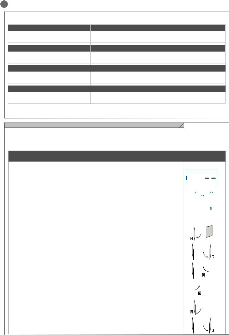
AUTOAPPRENDIMENTO DELLA CORSA E DEI PARAMETRI PRINCIPALI, CON
RALLENTAMENTI PREIMPOSTATI
I rallentamenti saranno quelli impostati da menù con la medesima percentuale sia in apertura che in chiusura.
ATTENZIONE: se si desidera programmare manualmente anche i rallentamenti passare direttamente alla tabella successiva
1. |
ATTENZIONE: verificare l’esistenza e la solidità dei fermi meccanici, che sono obbligatori. I motori |
|
|
|
|
|
|
|
|
|
|
|
|
|
|
|
|
|
|
|
|
|
|
|
|
|
|
|
|
|
|
|
|
|
|
|
|
|
|
|
|
||
devono obbligatoriamente andare in battuta meccanica |
|
|
|
UP |
|
|
|
DOWN |
|||||||||||||
2. |
Portare manualmente le ante a metà della corsa |
|
|
|
|
|
|
|
|
|
|
|
|
|
|
|
|
|
|
|
|
|
|
|
|
|
|
|
|
|
|
|
|
|
|
|
|
|
|
|
|
||
|
|
|
|
|
|
|
|
|
|
|
|
|
|
|
|
|
|
|
|
||
3. |
Premere CONTEMPORANEAMENTE i tasti UP + e MENU per più di 5 secondi fino a visualizzare LOP e |
|
|
|
|
|
|
MENU |
|
|
|
|
|
|
|
|
|
|
|
|
|
|
|
|
|
|
|
|
|
|
|
|
|
|
|
|
|
|
|
|
|
||
prepararsi a premere (se necessario) il tasto DOWN (vedi figura). |
|
|
|
|
|
|
|
|
|
|
|
|
|
|
|
|
|
|
|
|
|
Verificare che il motore M1 apra per primo, se così non fosse premere DOWN -, togliere la tensione e inverti- |
|
|
|
|
|
|
|
|
|
|
|
|
|
|
|
|
|
|
|
|
|
|
|
|
|
|
|
|
|
|
|
|
|
|
|
|
|
|
|
|
|
||
re i collegamenti di M1 e M2. Ripetere la procedura dal punto 3. |
|
|
|
|
|
|
|
|
|
|
|
|
|
|
|
|
|
|
|
||
|
|
|
|
|
|
|
|
|
SS |
|
|
|
|
|
|
||||||
Se la prima manovra NON è un’apertura premere il tasto DOWN - per fermare l’autoapprendimento. Premere |
|
|
|
|
|
|
|
|
|
|
|
|
|
|
|
|
|
|
|
|
|
quindi SS in modo da far ripartire l’acquisizione: l’anta riprende a muoversi in senso corretto. |
|
|
|
|
|
|
|
|
|
|
|
|
|
|
|
|
|
|
|
|
|
4. |
Il motore M1 apre a bassa velocità fino al raggiungimento della battuta meccanica di apertura. |
|
|
|
|
M1 |
|
|
M2 |
|
|
|
|
|
4 |
|
|||||
|
|
|
|
|
|
|
|
|
|
|
|
||||||||||
Esattamente al raggiungimento della battuta meccanica di apertura inviare un comando di SS. |
|
|
|
|
|
|
|
|
|
|
|
|
|
|
|
|
|||||
|
|
|
|
|
|
|
|
|
|
|
|
|
|
|
|
|
|
|
|
||
Parte in automatico il motore M2 in apertura. Se il motore M2 muove in chiusura fermare con DOWN - e |
|
|
|
|
|
|
|
|
|
|
|
|
|
|
|
|
|
|
|
|
|
|
|
|
|
|
|
|
|
|
|
|
|
|
|
|
|
|
|
|
|
||
riprendere la movimentazione con SS (l’anta riprende a muoversi in senso corretto) |
|
|
|
|
|
|
|
|
|
|
|
|
|
|
|
|
|
|
|
||
|
|
|
|
|
|
|
|
|
|
|
|
|
|
|
|
|
|
|
|||
|
SS |
|
|
|
|
|
|
|
|
|
|
|
|
|
|
||||||
5. |
Il motore M2 apre a bassa velocità. Esattamente al raggiungimento della battuta meccanica di aper- |
|
|
|
M1 |
|
|
M2 |
|
|
|
|
5 |
|
|||||||
|
|
|
|
|
|
|
|
|
|
||||||||||||
|
|
|
|
|
|
|
|
|
|
|
|
|
|
|
|
|
|
|
|
||
tura inviare un comando di SS. Dopo un paio di secondi il motore M2 parte automaticamente in chiusura a |
|
|
|
|
|
|
|
|
|
|
|
|
|
|
|
|
|
|
|
|
|
velocità piena. |
|
|
|
|
|
|
|
|
|
|
|
|
|
|
|
|
|
|
|
|
|
|
|
|
|
|
|
|
|
|
|
|
|
|
|
|
|
|
|
|
|
||
|
|
|
|
|
|
|
|
|
|
|
|
|
|
|
|
|
|
|
|
||
|
|
|
|
|
|
|
|
|
|
|
|
|
|
SS |
|||||||
6. |
Quando il motore M2 raggiunge esattamente la posizione di chiusura, inviare un comando di SS. Il |
|
|
|
M1 |
|
|
|
|
|
|
|
6 |
|
|||||||
|
|
|
|
M2 |
|
|
|
|
|||||||||||||
motore M2 si ferma e parte in chiusura il motore M1. |
|
|
|
|
|
|
|
|
|
|
|
|
|
|
|
|
|
|
|
|
|
|
|
|
|
|
|
|
|
|
|
|
|
|
|
|
|
|
|
|
|
||
|
|
|
|
|
|
|
|
|
|
|
|
|
|
|
|
|
|
|
|
||
|
|
|
|
|
|
|
|
|
|
|
|
|
|
|
|
|
|
|
|
||
|
|
|
|
|
|
|
|
SS |
|
|
|
|
|
|
|
|
|||||
7. |
Quando il motore M1 raggiunge esattamente la posizione di chiusura, inviare un comando di SS. Il |
|
|
|
|
|
|
|
|
|
7 |
|
|
|
|||||||
|
|
|
M1 |
|
M2 |
|
|
|
|
|
|
||||||||||
motore M1 si ferma e riparte in apertura. |
|
|
|
|
|
|
|
|
|
|
|
|
|
|
|
|
|
|
|
|
|
|
|
|
|
|
|
|
|
|
|
|
|
|
|
|
|
|
|
|
|
||
|
|
|
|
|
|
|
SS |
|
|
|
|
|
|
|
|
||||||
8. |
Quando il motore M1 raggiunge esattamente la posizione di apertura, inviare un comando di SS. Il |
|
|
|
|
M1 |
|
|
|
|
|
|
|
|
8 |
|
|||||
|
|
|
|
|
|
M2 |
|
|
|
|
|
|
|
||||||||
motore M1 si ferma e parte in apertura il motore M2. |
|
|
|
|
|
|
|
|
|
|
|
|
|
|
|
|
|
|
|
|
|
|
|
|
|
|
|
|
|
|
|
|
|
|
|
|
|
|
|
|
|
||
|
|
|
|
|
|
|
|
|
|
|
|
|
|
|
|
|
|
|
|||
|
|
|
|
|
|
|
|
|
|
|
|
|
|
|
|
|
|
|
|||
|
|
|
SS |
|
|
|
|
|
|
|
|
|
|
|
|
|
|
||||
9. |
Quando il motore M2 raggiunge esattamente la posizione di apertura, inviare un comando di SS. Il |
|
|
|
M1 |
|
|
M2 |
|
|
|
9 |
|
||||||||
|
|
|
|
|
|
|
|
|
|
||||||||||||
motore M2 si ferma. |
|
|
|
|
|
|
|
|
|
|
|
|
|
|
|
|
|
|
|
|
|
|
|
|
|
|
|
|
|
|
|
|
|
|
|
|
|
|
|||||
|
|
|
|
|
|
|
|
|
|
|
|
|
|
SS |
|||||||
8
IT
|
|
|
|
|
|
10. La movimentazione di M1 e M2 riprende in chiusura rispettando lo sfasamento delle ante impostato da |
|
M1 |
M2 |
|
10 |
|
|
|
|
|
|
menu, ovvero il cancello si chiuderà autonomamente secondo la corsa programmata. |
|
|
|
|
|
|
|
|
|
|
|
11. Effettuare alcune manovre di apertura, chiusura e stop improvviso verificando il sistema sia solido e che non vi siano difetti di montaggio.
Tutti i parametri principali sono configurati di default dalla centrale. Per personalizzare l’installazione procedere con il prossimo paragrafo 4.4.
Se la coppia non fosse sufficiente per muovere l’anta eliminare i rallentamenti da menu [LSI=0].
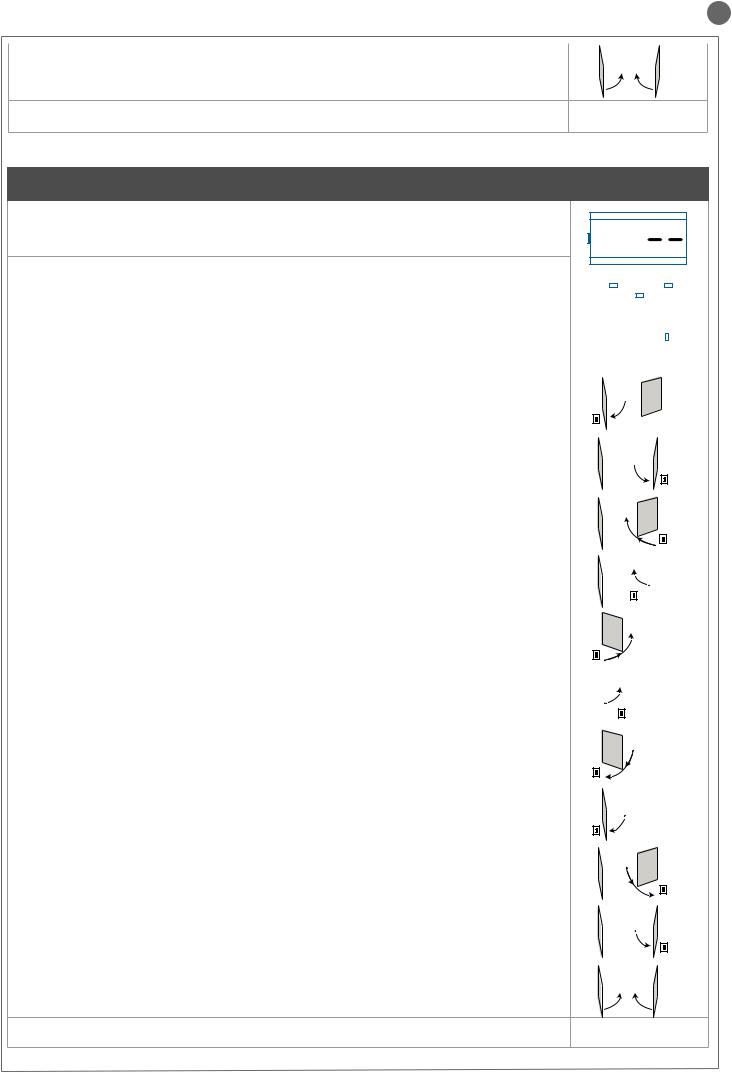
AUTOAPPRENDIMENTO DELLA CORSA E DEI PARAMETRI PRINCIPALI, CON
RALLENTAMENTI PERSONALIZZATI
I rallentamenti sono personalizzabili dall’utente, mediante la procedura sottindicata
1.ATTENZIONE: verificare l’esistenza e la solidità dei fermi meccanici, che sono obbligatori. I motori devono obbligatoriamente andare in battuta meccanica
2.Portare manualmente le ante a metà della corsa
|
|
|
|
UP |
|
|
|
|
|
|
|
DOWN |
|||||||||||
3. ATTENZIONE: entrare nel menù base per impostare il parametroLSI = p come da tabella al paragrafo 4.4 |
|
|
|
|
|
|
|
|
|
|
|||||||||||||
|
|
|
|
|
|
|
|
|
|
|
|
|
|
|
|
|
|
|
|
|
|
|
|
4. Premere CONTEMPORANEAMENTE i tasti UP + e MENU per più di 5 secondi fino a visualizzare LOP e |
|
|
|
|
|
|
|
|
|
|
|
|
|
|
|
|
|
|
|
|
|
|
|
|
|
|
|
|
|
|
|
|
|
|
|
|
|
|
|
|
|
|
|
|
|
|
|
|
|
|
|
|
|
|
MENU |
|
|
|
|
|
|
|
|
|
|
|
|||||
prepararsi a premere (se necessario) il tasto DOWN (vedi figura). |
|
|
|
|
|
|
|
|
|
|
|
|
|
|
|
|
|
|
|||||
|
|
|
|
|
|
|
|
|
|
|
|
|
|
|
|
|
|
|
|
|
|
|
|
Verificare che il motore M1 apra per primo, se così non fosse premere DOWN -, togliere la tensione e invertire |
|
|
|
|
|
|
|
|
|
|
|
|
|
|
|
|
|
|
|
|
|
|
|
i collegamenti M1, M2. Ripetere la procedura dal punto 4. |
|
|
|
|
|
|
|
|
|
|
|
|
|
|
|
|
|
|
|
|
|
|
|
Se la prima manovra NON è un’apertura premere il tasto DOWN - per fermare l’autoapprendimento. Premere |
|
|
|
|
|
|
|
|
|
|
|
|
|
|
|
|
|
|
|
|
|
|
|
|
|
|
|
|
|
|
|
|
|
|
|
|
|
SS |
|
||||||||
quindi SS in modo da far ripartire l’acquisizione: l’anta riprende a muoversi in senso corretto. |
|
|
|
|
|
|
|
|
|
|
|
|
|
|
|
|
|
|
|
|
|
|
|
5. Il motore M1 apre a bassa velocità fino al raggiungimento della battuta meccanica di apertura. |
|
|
M1 |
|
|
M2 |
|
|
|
|
|
|
|
|
5 |
|
|||||||
|
|
|
|
|
|
|
|
|
|
|
|
|
|||||||||||
Esattamente al raggiungimento della battuta meccanica di apertura inviare un comando di SS. |
|
|
|
|
|
|
|
|
|
|
|
|
|
|
|
|
|
|
|
||||
Parte in automatico il motore M2 in apertura. Se il motore M2 muove in chiusura fermare con DOWN - e |
|
|
|
|
|
|
|
|
|
|
|
|
|
|
|
|
|
|
|
|
|
|
|
riprendere la movimentazione con SS (l’anta riprende a muoversi in senso corretto). |
SS |
|
|
|
|
|
|
|
|
|
|
|
|
|
|
|
|
|
|||||
|
|
|
|
|
|
|
|
|
|
|
|
|
|
|
|
|
|
||||||
6. Il motore M2 apre a bassa velocità. Esattamente al raggiungimento della battuta meccanica di aper- |
|
|
M1 |
|
M2 |
|
|
|
|
|
6 |
|
|
||||||||||
|
|
|
|
|
|
|
|
|
|
||||||||||||||
tura inviare un comando di SS. Dopo un paio di secondi il motore M2 parte automaticamente in chiusura a |
|
|
|
|
|
|
|
|
|
|
|
|
|
|
|
|
|
|
|
|
|
|
|
velocità piena. |
|
|
|
|
|
|
|
|
|
|
|
|
|
|
|
|
|
|
|
|
|
|
|
|
|
|
|
|
|
|
|
|
|
|
|
|
|
|
|
|
|
|
|
|
|
|
|
|
|
|
|
|
|
|
|
|
|
|
|
|
|
|
|
|
|
|
|
|
|||
|
|
|
|
|
|
|
|
|
|
|
|
|
|
SS |
|||||||||
7. Raggiunto il punto in cui si desidera inizi il rallentamento in chiusura del motore M2 inviare un |
|
|
M1 |
|
M2 |
|
|
|
|
|
7 |
|
|
||||||||||
|
|
|
|
|
|
|
|
|
|
||||||||||||||
comando di SS. La movimentazione del motore M2 continua a velocità ridotta. |
|
|
|
|
|
|
|
|
|
|
|
|
|
|
|
|
|
|
|
||||
|
|
|
|
|
|
|
|
|
|
|
|
|
|
|
|
|
|
|
|
|
|
|
|
|
|
|
|
|
|
|
|
|
|
|
|
|
|
|
|
|
|
|
|
|
|
||
|
|
|
|
|
|
|
|
|
|
|
|
|
|
SS |
|||||||||
8. Quando il motore M2 raggiunge esattamente la posizione di chiusura, inviare un comando di SS. Il |
|
|
M1 |
|
|
|
|
|
|
|
8 |
|
|
||||||||||
|
|
|
M2 |
|
|
|
|
|
|
|
|||||||||||||
motore M2 si ferma e parte in chiusura il motore M1. |
|
|
|
|
|
|
|
|
|
|
|
|
|
|
|
|
|
|
|
|
|
|
|
|
|
|
|
|
|
|
|
|
|
|
|
|
|
|
|
|
|
|
|
|
|
||
|
|
|
|
|
|
|
|
|
|
|
|
|
|
|
|
|
|
|
|
|
|||
|
|
|
|
|
|
|
|
|
|
|
|
|
|
|
|
|
|
|
|
|
|||
|
|
|
|
|
|
|
SS |
|
|
|
|
|
|
|
|
|
|
|
|||||
9. Raggiunto il punto in cui si desidera inizi il rallentamento in chiusura del motore M1 inviare un |
|
|
|
|
|
|
|
|
|
|
|
|
9 |
|
|||||||||
|
|
M1 |
|
M2 |
|
|
|
|
|
|
|||||||||||||
comando di SS. La movimentazione del motore M1 continua a velocità ridotta. |
|
|
|
|
|
|
|
|
|
|
|
|
|
|
|
|
|
|
|
|
|
|
|
|
|
|
|
|
|
|
|
|
|
|
|
|
|
|
|
|
|
|
|
|
|
||
|
SS |
|
|
|
|
|
|
|
|
|
|
|
|
|
|
|
|
|
|||||
10. Quando il motore M1 raggiunge esattamente la posizione di chiusura, inviare un comando di SS. Il |
|
|
|
|
|
|
|
|
10 |
|
|
||||||||||||
|
|
M1 |
|
|
M2 |
|
|
|
|
|
|
||||||||||||
motore M1 si ferma e riparte in apertura. |
|
|
|
|
|
|
|
|
|
|
|
|
|
|
|
|
|
|
|
|
|
|
|
|
|
|
|
|
|
|
|
|
|
|
|
|
|
|
|
|
|
|
|
|
|
|
|
|
|
|
|
SS |
|
|
|
|
|
|
|
|
|
|
|
|
|
|
|
|
|
||
11. Raggiunto il punto in cui si desidera inizi il rallentamento in apertura del motore M1 inviare un |
|
|
|
|
|
|
|
|
|
|
|
11 |
|||||||||||
|
|
M1 |
|
M2 |
|
|
|
|
|
|
|||||||||||||
comando di SS. La movimentazione del motore M1 continua a velocità ridotta. |
|
|
|
|
|
|
|
|
|
|
|
|
|
|
|
|
|
|
|
|
|
|
|
|
|
|
|
|
|
|
|
|
|
|
|
|
|
|
|
|
|
|
|
|
|||
|
SS |
|
|
|
|
|
|
|
|
|
|
|
|
|
|
|
|
|
|||||
12. Quando il motore M1 raggiunge esattamente la posizione di apertura, inviare un comando di SS. Il |
|
|
M1 |
|
|
|
|
|
|
|
|
12 |
|||||||||||
|
|
|
M2 |
|
|
|
|
|
|
||||||||||||||
motore M1 si ferma e parte in apertura il motore M2. |
|
|
|
|
|
|
|
|
|
|
|
|
|
|
|
|
|
|
|
|
|
|
|
|
|
|
|
|
|
|
|
|
|
|
|
|
|
|
|
|
|
|
|
|
|||
|
|
|
|
|
|
|
|
|
|
|
|
|
|
|
|
|
|
|
|
|
|||
|
|
|
|
|
|
|
|
|
|
|
|
|
|
|
|
|
|
|
|
|
|||
|
SS |
|
|
|
|
|
|
|
|
|
|
|
|
|
|
|
|
|
|||||
13. Raggiunto il punto in cui si desidera inizi il rallentamento in apertura del motore M2 inviare un |
|
|
M1 |
|
M2 |
|
|
|
13 |
|
|||||||||||||
|
|
|
|
|
|
|
|
|
|||||||||||||||
comando di SS. La movimentazione del motore M2 continua a velocità ridotta. |
|
|
|
|
|
|
|
|
|
|
|
|
|
|
|
|
|
|
|||||
|
|
|
|
|
|
|
|
|
|
|
|
|
|
|
|
|
|
|
|
|
|
|
|
|
|
|
|
|
|
|
|
|
|
|
|
|
|
|
|
|
|||||||
|
|
|
|
|
|
|
|
|
|
|
|
|
|
SS |
|||||||||
14. Quando il motore M2 raggiunge esattamente la posizione di apertura, inviare un comando di SS. Il |
|
|
M1 |
|
M2 |
|
|
|
14 |
|
|||||||||||||
|
|
|
|
|
|
|
|
|
|||||||||||||||
motore M2 si ferma. |
|
|
|
|
|
|
|
|
|
|
|
|
|
|
|
|
|
|
|
|
|
|
|
|
|
|
|
|
|
|
|
|
|
|
|
|
|
|
|
|
|||||||
|
|
|
|
|
|
|
|
|
|
|
|
|
|
SS |
|||||||||
15. La movimentazione di M1 e M2 riprende in chiusura rispettando lo sfasamento delle ante impostato |
|
|
M1 |
|
M2 |
|
|
|
|
|
15 |
||||||||||||
|
|
|
|
|
|
|
|
||||||||||||||||
da menu, ovvero il cancello si chiuderà autonomamente secondo la corsa programmata. |
|
|
|
|
|
|
|
|
|
|
|
|
|
|
|
|
|
|
|
|
|
|
|
|
|
|
|
|
|
|
|
|
|
|
|
|
|
|
|
|
|
|
|
|
|
|
|
16. Effettuare alcune manovre di apertura, chiusura e stop improvviso verificando il sistema sia solido e che non vi siano difetti di montaggio.
Tutti i parametri principali sono configurati di default dalla centrale. Per personalizzare l’installazione procedere con il prossimo paragrafo 4.4.
9
IT
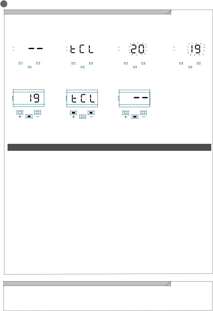
4.4 - Personalizzazione dell’impianto - MENU BASE
In caso di necessità è possibile selezionare un MENU BASE che permette di modificare i parametri base della unità di controllo. Per selezionare il MENU BASE procedere come sotto riportato.
ATTENZIONE: per portarsi con certezza allo stato di visualizzazione definito come FUNZIONE NORMALE, punto di partenza per accedere al MENU BASE, premere 2 volte il tasto MENU
Esempio di modifica di un parametro del MENU BASE
|
|
|
|
|
|
|
|
|
|
|
|
|
|
|
|
|
|
|
|
|
|
|
|
|
|
|
|
|
|
|
|
|
|
|
|
|
|
|
|
|
|
|
|
|
|
|
|
|
|
|
|
|
|
|
|
|
|
|
|
|
|
|
|
|
|
|
|
|
|
|
|
|
|
|
|
|
|
|
|
|
|
|
|
|
|
|
|
|
|
|
|
|
|
|
|
|
|
|
|
|
|
|
|
|
|
|
|
|
|
|
|
|
|
|
|
|
|
|
|
|
|
|
|
|
|
|
|
|
|
|
|
|
|
|
|
|
|
|
|
|
|
|
|
|
|
|
|
|
|
|
|
|
|
|
|
|
|
|
|
|
|
|
|
|
|
|
|
|
|
|
|
|
|
|
|
|
|
|
|
|
|
|
|
|
|
|
|
|
|
|
|
|
|
|
|
|
|
|
|
|
|
|
|
|
|
|
|
|
|
|
|
|
|
|
|
|
|
|
|
|
|
|
|
|
|
|
|
|
|
|
|
|
|
|
|
|
|
|
|
|
|
|
|
|
|
|
|
|
|
|
|
|
|
|
|
|
|
|
|
|
|
|
|
|
|
|
|
|
|
|
|
|
|
|
|
|
|
|
|
|
|
|
UP |
|
|
|
|
|
DOWN |
|
|
UP |
|
|
|
DOWN |
|
|
|
UP |
|
|
|
|
|
DOWN |
|
|
|
UP |
|
|
|
DOWN |
|||||||||||||||||||||
|
|
|
|
|
|
|
MENU |
|
|
|
|
|
|
|
|
|
|
|
MENU |
|
|
|
|
|
|
|
|
|
|
|
MENU |
|
|
|
|
|
|
|
|
|
|
|
MENU |
|
|
|
|
||||||||
|
|
|
|
|
|
|
|
|
|
|
|
|
|
|
|
|
|
|
|
|
|
|
|
|
|
|
|
|
|
|
|
|
|
|
|
|
|
|
|
|
|
|
|
||||||||||||
|
|
|
|
|
|
|
|
|
|
|
|
|
|
|
|
|
|
|
|
|
|
|
|
|
|
|
|
|
|
|
|
|
|
|
|
|
|
|
|
|
|
|
|
||||||||||||
|
|
|
|
|
|
|
|
|
|
|
|
|
|
|
|
|
|
|
|
|
|
|
|
|
|
|
|
|
|
|
|
|
|
|
|
|
|
|
|
|
|
|
|
|
|
|
|
|
|
|
|
|
|
|
|
|
|
|
|
|
|
|
|
|
|
|
|
|
|
|
|
|
|
|
|
|
|
|
|
|
|
|
|
|
|
|
|
|
|
|
|
|
|
|
|
|
|
|
|
|
|
|
|
|
|
|
|
|
|
|
|
Premere il tasto MENU per 1 secondo per entrare nel menu’ base.
Entrati nel MENU BASE premere i tasti + e – per scorrere le funzioni.
Per entrare in modifica valore, premere il tasto MENU per 1 secondo finche’ il valore lampeggia velocemente
Premere i tasti + e – per modificare il valore.
UP DOWN
MENU
Premere il tasto MENU per 1 secondo fino a visualizzare il valore fisso per salvare il valore modificato oppure MENU velocemente per uscire senza salvare.
UP DOWN
MENU
Premere i tasti + o – per scorrere le funzioni per modificare altri parametri.
UP DOWN
MENU
Premere il tasto MENU velocemente per uscire dal menu.
|
PARAMETRI |
|
DESCRIZIONE |
DEFAULT |
MIN |
MAX |
UNITA’ |
|||
1 |
TCL |
Tempo richiusura automatica (0 = disabilitato) |
20 |
0 |
900 |
s |
||||
2 |
ttr |
Tempo richiusura dopo il transito (0 = disabilitato) |
0 |
0 |
30 |
s |
||||
3 |
SEI |
Sensibilità su ostacolo |
0 |
0 |
100 |
% (step |
||||
(0 = disabilitato) |
da 1) |
|||||||||
|
|
|
|
|
|
|
||||
4 |
trq |
Forza motore (coppia a regime) |
100 |
10 |
100 |
% (step |
||||
da 10) |
||||||||||
|
|
|
|
|
|
|
|
|
||
5 |
SSL |
Modalità rallentamento |
|
|
|
|
||||
0 |
= rallentamento 1/3 (lento) |
0 |
0 |
1 |
|
|||||
|
|
|
|
1 |
= rallentamento 2/3 (veloce) |
|
|
|
|
|
|
|
|
|
Configurazione SS: |
|
|
|
|
||
|
|
|
|
0 |
= Normale (AP-ST-CH-ST-AP-ST…) |
|
|
|
|
|
6 |
SbS |
1 |
= Alternato STOP (AP-ST-CH-AP-ST-CH…) |
0 |
0 |
4 |
|
|||
2 |
= Alternato (AP-CH-AP-CH…) |
|
||||||||
|
|
|
|
|
|
|
|
|||
|
|
|
|
3 |
= Condominiale – timer |
|
|
|
|
|
|
|
|
|
4 |
= Condominiale con richiusura immediata |
|
|
|
|
|
7 |
bLt |
Comportamento dopo black out |
|
|
|
|
||||
0 |
= nessuna azione, rimane com’era |
0 |
0 |
1 |
|
|||||
|
|
|
|
1 |
= Chiusura |
|
|
|
|
|
8 |
SST |
Soft start (partenza rallentata) |
|
|
|
|
||||
0 |
= disabilitato |
0 |
0 |
1 |
|
|||||
|
|
|
|
1 |
= abilitato |
|
|
|
|
|
9 |
dLY |
Ritardo seconda anta |
2 |
0 |
300 |
s |
||||
10 |
LSI |
Ampiezza rallentamento |
|
|
|
% (step |
||||
P = personalizzato da apprendimento |
15 |
0 |
100 |
|||||||
da 1) |
||||||||||
|
|
|
|
0...100% = percentuale della corsa |
|
|
|
|||
|
|
|
|
|
|
|
|
|||
11 |
ASL |
Antislittamento: prolunga il tempo di lavoro impostato |
0 |
0 |
300 |
s |
||||
(utile in zone soggette a forte vento) |
||||||||||
|
|
|
|
|
|
|
|
|||
12 |
|
n |
|
Numero motori |
|
|
|
|
||
|
|
1 |
= 1 motore |
1 |
1 |
2 |
|
|||
nMt |
|
|||||||||
|
|
|
|
2 |
= 2 motori |
|
|
|
|
|
4.5 - Innesto ricevente radio
Innestare la ricevente radio facendo attenzione alla direzione come indicato nella figura al paragrafo 2.1.
Per la programmazione seguire le istruzioni della ricevente sapendo
che le 4 uscite attivabili sono: USCITA 1 = PASSO PASSO, USCITA 2 = PEDONALE, USCITA 3 = APRE, USCITA 4 = CHIUDE.
10
IT
5 - COLLAUDO E MESSA IN SERVIZIO DELL’AUTOMAZIONE
Il collaudo dell’impianto va eseguito da un tecnico qualificato che deve effettuare le prove richieste dalla normativa di riferimento in funzione dei rischi presenti, verificando il rispetto di quanto previsto
dalle normative, in particolare la norma EN12445 che indica i metodi di prova per gli automatismi per porte e cancelli.
5.1 - Collaudo
Tutti i componenti dell’impianto devono essere collaudati seguendo le procedure indicate nei rispettivi manuali di istruzioni;
controllare che siano rispettate le indicazioni del Capitolo 1 – Avvertenze per la sicurezza;
controllare che il cancello o la porta si possano muovere liberamente una volta sbloccata l’automazione e che siano in equilibrio e rimangano quindi fermi se lasciati in qualsiasi posizione;
controllare il corretto funzionamento di tutti i dispositivi collegati (fotocellule, bordi sensibili, pulsanti di emergenza, altro) effettuando delle prove di apertura, chiusura e arresto del cancello o della porta tramite i dispositivi di comando collegati (trasmettitori, pulsanti, selettori);
effettuare le misurazioni della forza d’impatto come previsto dalla normativa EN12445 regolando le funzioni di velocità, forza motore e rallentamenti della centrale nel caso in cui le misurazioni non diano i risultati desiderati fino a trovare il giusto settaggio.
5.2 - Messa in servizio
A seguito del positivo collaudo di tutti (e non solo di alcuni) i dispositivi dell’impianto si può procedere con la messa in servizio;
è necessario realizzare e conservare per 10 anni il fascicolo tecnico dell’impianto che dovrà contenere lo schema elettrico, il disegno o foto dell’impianto, l’analisi dei rischi e le soluzioni adottate, la dichiarazione di conformità del fabbricante di tutti i dispositivi collegati, il manuale istruzioni di ogni dispositivo e il piano di manutenzione dell’impianto;
fissare sul cancello o la porta una targa indicante i dati dell’automazione, il nome del responsabile della messa in servizio, il numero di matricola e l’anno di costruzione, il marchio CE;
fissare una targa che indichi le operazioni necessarie per sbloccare manualmente l’impianto;
realizzare e consegnare all’utilizzatore finale la dichiarazione di conformità , le istruzioni e avvertenze d’uso per l’utilizzatore finale e il piano di manutenzione dell’impianto;
accertarsi che l’utilizzatore abbia compreso il corretto funzionamento automatico, manuale e di emergenza dell’automazione;
informare anche in forma scritta l’utilizzatore finale sui pericoli e rischi ancora presenti;
ATTENZIONE - dopo la rilevazione di un ostacolo, il cancello o la porta si ferma in apertura e viene esclusa la chiusura automatica; per riprendere il movimento bisogna premere il pulsante di comando o usare il trasmettitore.
11

IT
6 - APPROFONDIMENTI - MENU AVANZATO
Il MENU AVANZATO permette di personalizzare ulteriormente l’impianto modificando dei parametri non accessibili dal menu base.
Per accedere al menu AVANZATO si preme e si tiene premuto per
5 secondi il tasto MENU.
Per modificare i parametri del MENU AVANZATO si procede come indicato per il MENU BASE.
|
PARAMETRI |
|
DESCRIZIONE |
DEFAULT |
MIN |
MAX |
UNITA’ |
||
|
|
EL.F. |
Elettrofreno |
|
|
|
x 0.01s |
||
1 |
|
0 |
= disabilitato |
0 |
0 |
100 |
|||
|
(step da 5) |
||||||||
|
|
|
|
1 |
= abilitato |
|
|
|
|
|
|
SP.h. |
Comportamento PHOTO1 in partenza da chiuso |
|
|
|
|
||
2 |
|
0 |
= Verifica PHOTO1 |
1 |
0 |
1 |
|
||
|
|
|
|
1 |
= Il cancello apre anche con PHOTO1 impegnata |
|
|
|
|
|
|
Ph.2. |
Comportamento PHOTO2 |
|
|
|
|
||
3 |
|
0 |
= Abilitata sia in apertura che in chiusura AP/CH |
0 |
0 |
1 |
|
||
|
|
|
|
1 |
= Abilitata solo in apertura AP |
|
|
|
|
|
|
|
|
Test fotodispositivi |
|
|
|
|
|
|
|
tP.h. |
0 |
= disabilitato |
|
|
|
|
|
4 |
|
1 |
= abilitato PHOTO1 |
0 |
0 |
3 |
|
||
|
|
|
|
2 |
= abilitato PHOTO2 |
|
|
|
|
|
|
|
|
3 |
= abilitato PHOTO1 e PHOTO2 |
|
|
|
|
|
|
|
n |
Tipologia costa |
|
|
|
|
|
5 |
|
ed.M. |
0 |
= contatto (NC) |
0 |
0 |
1 |
|
|
|
|
|
|
1 |
= resistiva (8k2) |
|
|
|
|
|
|
|
|
Modalità intervento costa |
|
|
|
|
|
6 |
|
iE.D. |
0 |
= interviene solo in chiusura con inversione del moto |
0 |
0 |
1 |
|
|
|
1 |
= ferma l’automazione (sia apertura che chiusura) e libera |
|
||||||
|
|
|
|
l’ostacolo (breve inversione) |
|
|
|
|
|
|
|
tE.D. |
Test costa |
|
|
|
|
||
7 |
|
0 |
= disabilitato |
0 |
0 |
1 |
|
||
|
|
|
|
1 |
= abilitato |
|
|
|
|
8 |
|
LP.o. |
Apertura pedonale |
30 |
0 |
100 |
% (step da 1) |
||
9 |
|
TP.C. |
Tempo richiusura automatica da pedonale (0 = disabilitato) |
20 |
0 |
900 |
s |
||
|
|
FP.r. |
Configurazione uscita lampeggiante |
|
|
|
|
||
10 |
|
0 |
= Fissa |
1 |
0 |
1 |
|
||
|
|
|
|
1 |
= Lampeggiante |
|
|
|
|
11 |
|
tP.r. |
Tempo prelampeggio |
0 |
0 |
10 |
s |
||
|
(0 = disabilitato) |
||||||||
|
|
|
|
Configurazione luce di cortesia |
|
|
|
|
|
|
|
|
|
0 |
= A fine manovra accesa per tempo TCY |
|
|
|
|
12 |
|
FC.Y. |
1 |
= Accesa se cancello non chiuso + durata TCY |
0 |
0 |
4 |
|
|
|
2 |
= Accesa se timer luce di cortesia (TCY) non scaduto |
|
||||||
|
|
|
|
3 |
= Spia cancello aperto on/off |
|
|
|
|
|
|
|
|
4 |
= Spia cancello aperto lampeggio proporzionale |
|
|
|
|
13 |
|
tC.Y. |
Tempo durata luce di cortesia |
0 |
0 |
900 |
s (step da |
||
|
10s) |
||||||||
|
|
dE.A. |
Uomo presente |
|
|
|
|
||
14 |
|
0 |
= disabilitato |
0 |
0 |
1 |
|
||
|
|
|
|
1 |
= abilitato |
|
|
|
|
|
|
|
|
Soglia cicli richiesta assistenza. Raggiunta la soglia |
|
|
|
|
|
15 |
|
se.r. |
impostata i cicli successivi verranno eseguiti con |
0 |
0 |
100 |
x 1000 cicli |
||
|
lampeggio veloce (solo se FPr è attivo). |
||||||||
|
|
|
|
(0 = disabilitato) |
|
|
|
|
|
|
|
|
|
Abilitazione al lampeggio continuo per richiesta assistenza |
|
|
|
|
|
16 |
|
se.f. |
(funzione eseguita solo a cancello chiuso). |
0 |
0 |
1 |
|
||
|
0 |
= disabilitato |
|
||||||
|
|
|
|
1 |
= abilitato |
|
|
|
|
17 |
|
HA.o. |
Colpo d’ariete in apertura |
0 |
0 |
100 |
*100ms |
||
|
0 |
= disabilitato |
|||||||
18 |
|
HA.c. |
Colpo d’ariete in chiusura |
0 |
0 |
100 |
*100ms |
||
|
0 |
= disabilitato |
|||||||
|
|
n |
|
Intervallo di mantenimento pressione motori idraulici |
|
|
|
|
|
|
|
|
0 |
= disabilitato |
|
|
|
|
|
19 |
|
mp.r. |
da 1 a 480 abilitato nel seguente modo: 1 = 1 min. ON e 1 min OFF, |
0 |
0 |
480 |
minuti |
||
|
|
|
|
2 |
= 1 min. ON e 2 min. OFF, ... |
|
|
|
|
20 |
|
de.f. |
Ripristino valori di default |
|
|
|
|
||
Per impostare i valori di default: 1) entrare in programmazione avanzata; 2) selezionare il parametro “def”; 3) attivare il modo modifica (si visualizza “0”); 4) accettare la modifica (premere “MENU”
e mantenerlo premuto). A questo punto si deve visualizzare un conto alla rovescia d80,d79...,d01 fino a “don“. Alla fine rilasciare il tasto.
12

IT
7 - ISTRUZIONI ED AVVERTENZE DESTINATE ALL’UTILIZZATORE FINALE
Key Automation S.r.l. produce sistemi per l’automazione di cancelli, porte garage, porte automatiche, serrande, barriere per parcheggi e stradali. Key Automation non è però il produttore della vostra automazione, che è invece il risultato di un’opera di analisi, valutazione, scelta dei materiali, e realizzazione dell’impianto eseguita dal vostro installatore di fiducia. Ogni automazione è unica e solo il vostro installatore possiede l’esperienza e la professionalità necessarie ad eseguire un impianto secondo le vostre esigenze, sicuro ed affidabile nel tempo, e soprattutto a regola d’arte, rispondente cioè alle normative in vigore. Anche se l’automazione in vostro possesso soddisfa il livello di sicurezza richiesto dalle normative, questo non esclude l’esistenza di un “rischio residuo”, cioè la possibilità che si possano generare situazioni di pericolo, solitamente dovute ad un utilizzo incosciente o addirittura errato, per questo motivo desideriamo darvi alcuni consigli sui comportamenti da seguire:
•prima di usare per la prima volta l’automazione, fatevi spiegare dall’installatore l’origine dei rischi residui;
•conservate il manuale per ogni dubbio futuro e consegnatelo ad un eventuale nuovo proprietario dell’automazione;
•un uso incosciente ed improprio dell’automazione può farla diventare pericolosa: non comandate il movimento dell’automazione se nel suo raggio di azione si trovano persone, animali o cose;
•se adeguatamente progettato un impianto di automazione garantisce un alto grado di sicurezza, impedendo con i suoi sistemi di rilevazione il movimento in presenza di persone o cose, e garantendo un’attivazione sempre prevedibile e sicura. È comunque prudente vietare ai bambini di giocare in prossimità dell’automazione e per evitare attivazioni involontarie non lasciare i telecomandi alla loro portata.
•non appena notate qualunque comportamento anomalo da parte dell’automazione, togliete alimentazione elettrica all’impianto ed eseguite lo sblocco manuale. Non tentate da soli alcuna riparazione, ma richiedete l’intervento del vostro installatore di fiducia: nel frattempo l’impianto può funzionare come un’apertura non automatizzata, una volta sbloccato il motoriduttore con apposita chiave di sblocco data in dotazione con l’impianto. Con le sicurezze fuori uso è necessario far riparare quanto prima l’automatismo;
•in caso di rotture o assenza di alimentazione: attendete l’intervento del vostro installatore, o il ritorno dell’energia elettrica se l’impianto non è dotato di batterie tampone, l’automazione può essere azionata come una qualunque apertura non automatizzata. Per fare ciò è necessario eseguire lo sblocco manuale;
•sblocco e movimento manuale: prima di eseguire questa operazione porre attenzione che lo sblocco può avvenire solo quando l’anta è ferma.
•Manutenzione: Come ogni macchinario la vostra automazione ha bisogno di una manutenzione periodica affinché possa funzionare più a lungo possibile ed in completa sicurezza. Concordate con il vostro installatore un piano di manutenzione con frequenza periodica; Key Automation consiglia un intervento ogni 6 mesi per un normale utilizzo domestico, ma questo periodo può variare in funzione dell’intensità d’uso. Qualunque intervento di controllo, manutenzione o riparazione deve essere eseguito solo da personale qualificato.
•Non modificate l’impianto ed i parametri di programmazione e di regolazione dell’automazione: la responsabilità è del vostro installatore.
•Il collaudo, le manutenzioni periodiche e le eventuali riparazioni devono essere documentate da chi le esegue e i documenti conservati dal proprietario dell’impianto.
Gli unici interventi che vi sono possibili e vi consigliamo di effettuare periodicamente sono la pulizia dei vetrini delle fotocellule e la rimozione di eventuali foglie o sassi che potrebbero ostacolare l’automatismo. Per impedire che qualcuno possa azionare il cancello o la porta, prima di procedere, ricordatevi di sbloccare l’automatismo e di utilizzare per la pulizia solamente un panno leggermente inumidito con acqua.
• Al termine della vita dell’automazione, assicuratevi che lo smaltimento sia eseguito da personale qualificato e che i materiali vengano riciclati o smaltiti secondo le norme valide a livello locale.
Se il vostro trasmettitore dopo qualche tempo vi sembra funzionare peggio, oppure non funzionare affatto, potrebbe semplicemente dipendere dall’esaurimento della pila (a seconda dell’uso, possono trascorrere da diversi mesi fino ad oltre un anno). Ve ne potete accorgere dal fatto che la spia di conferma della trasmissione non si accende, oppure si accende solo per un breve istante.
Le pile contengono sostanze inquinanti: non gettarle nei rifiuti comuni ma utilizzare i metodi previsti dai regolamenti locali.
Vi ringraziamo per aver scelto Key Automation S.r.l. e vi invitiamo a visitare il nostro sito internet www.keyautomation.it per ulteriori informazioni.
13

EN
TABLE OF CONTENTS
1 |
|
|
|
|
|
|
|
Safety warnings |
pag. 15 |
||||
|
|
|
||||
2 |
|
|
|
|
|
|
|
Product Introduction |
pag. 16 |
||||
|
|
|
||||
2.1 |
Description of the control unit |
pag. 16 |
||||
2.2 |
Description of the connections |
pag. 16 |
||||
2.3 |
Models and technical characteristics |
pag. 16 |
||||
2.4 |
List of cables required |
pag. 17 |
||||
3 |
|
|
|
|
|
|
|
Preliminary Checks |
pag. 17 |
||||
|
|
|
||||
4 |
|
|
|
|
|
|
|
Installing the Product |
pag. 18 |
||||
|
|
|
||||
4.1 |
Electric connections |
pag. 18 |
||||
4.2 |
Display during normal operation |
pag. 19 |
||||
4.3 |
Autolearning of the travel stroke |
pag. 20 |
||||
4.4 |
Customising the system - BASIC MENU |
pag. 22 |
||||
4.5 |
Connecting the radio receiver |
pag. 22 |
||||
5 |
|
|
|
|
|
|
|
Testing and commissioning |
pag. 23 |
||||
|
|
|
||||
5.1 |
Testing |
pag. 23 |
||||
5.2 |
Commissioning |
pag. 23 |
||||
6 |
|
|
|
|
|
|
|
Further details - ADVANCED MENU |
pag. 24 |
||||
|
|
|
||||
7 |
|
|
|
|
|
|
|
|
Instructions and warnings for the |
pag. 25 |
|||
|
|
|
||||
|
|
|
final user |
|
|
|
8 |
|
|
|
|
|
|
|
|
EC declaration of conformity |
pag. 87 |
|||
|
|
|
||||
14

EN
1 - SAFETY WARNINGS
CAUTION – to ensure personal safety it is important to follow these instructions and keep them for future reference.
Read the instructions carefully before proceeding with installation.
The design and manufacture of the devices making up the product and the information in this manual are compliant with current safety standards. However, incorrect installation or programming may cause serious injury to those working on or using the system. Compliance with the instructions provided here when installing the product is therefore extremely important.
If in any doubt regarding installation, do not proceed and contact the
Key Automation Technical Service for clarifications.
Under European legislation, an automatic door or gate system must comply with the standards envisaged in the Directive 2006/42/EC (Machinery Directive) and in particular standards EN 12445; EN 12453; EN 12635 and EN 13241-1, which enable declaration of presumed conformity of the automation system.
Therefore, final connection of the automation system to the electrical mains, system testing, commissioning and routine maintenance must be performed by skilled, qualified personnel, in observance of the instructions in the “Testing and commissioning the automation system” section.
The aforesaid personnel are also responsible for the tests required to verify the solutions adopted according to the risks present, and for ensuring observance of all legal provisions, standards and regulations, with particular reference to all requirements of the EN 12445 standard which establishes the test methods for testing door and gate automation systems.
WARNING - Before starting installation, perform the following checks and assessments:
ensure that every device used to set up the automation system is suited to the intended system overall. For this purpose, pay special attention to the data provided in the “Technical specifications” section. Do not proceed with installation if any one of these devices is not suitable for its intended purpose;
check that the devices in the kit are sufficient to guarantee system safety and functionality;
perform a risk assessment, including a list of the essential safety requirements as envisaged in Annex I of the Machinery Directive, specifying the solutions adopted. The risk assessment is one of the documents included in the automation system’s technical file. This must be compiled by a professional installer.
Considering the risk situations that may arise during installation phases and use of the product, the automation system must be installed in compliance with the following safety precautions:
never make any modifications to part of the automation system other than those specified in this manual. Operations of this type can only lead to malfunctions. The manufacturer declines all liability for damage caused by unauthorised modifications to products.
do not allow parts of the automation system to be immersed in water or other liquids. During installation ensure that no liquids are able to enter the various devices;
should this occur, disconnect the power supply immediately and contact a Key Automation Service Centre. Use of the automation system in these conditions may cause hazards;
never place automation system components near to sources of heat or expose them to naked flames. This may damage system components and cause malfunctions, fire or hazards.
All operations requiring opening of the protective housings of various automation system components must be performed with the control unit disconnected from the power supply. If the disconnect device is not in a visible location, affix a notice stating: “MAINTENANCE IN PROGRESS”;
all devices must be connected to an electric power line equipped with an earthing system.
The product cannot be considered to provide effective protection against intrusion. If effective protection is required, the automation system must be combined with other devices;
the product may not be used until the automation system “commissioning” procedure has been performed as specified in the “Automation system testing and commissioning” section.
The system power supply line must include a circuit breaker device with a contact gap allowing complete disconnection in the conditions specified by class III overvoltage;
use unions with IP55 or higher protection when connecting hoses, pipes or raceways;
the electrical system upstream of the automation system must comply with the relevant regulations and be constructed to good workmanship standards;
users are advised to install an emergency stop button close to the automation system (connected to the control PCB STOP input) to allow the gate or door to be stopped immediate in case of danger;
this device product is not intended for use by persons (including children) with impaired physical, sensory or mental capacities, or with lack of experience or skill, unless a person responsible for their safety provides surveillance or instruction in use of the device;
children must be supervised to ensure that they do not play with the equipment.
WARNING - The automation system component packaging material must be disposed of in full observance of current local waste disposal legislation.
WARNING - The data and information in this manual are subject to modification at any time, with no obligation on the part of Key Automation S.r.l. to provide notice.
15
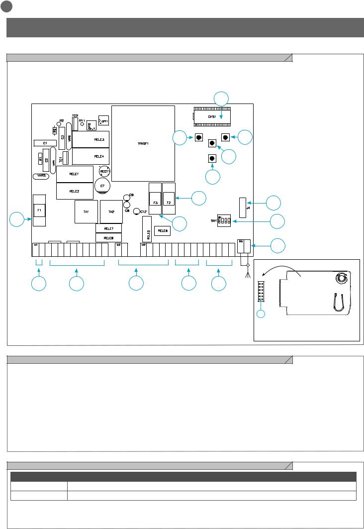
EN
2 - INTRODUCING THE PRODUCT
2.1 - Description of the control unit
The CT202 control unit is a state-of-the-art efficient control system for
Key Automation motors, for electrical opening and closing of swing gates.
Any other use is deemed improper and is strictly prohibited. The
CT202 control unit is equipped with a display to enable simple programming and constant monitoring of input status; the menu structure also enables easy entry of work times and operating logic.
|
|
|
|
|
|
|
|
|
|
8 |
|
|
|
|
|
|
|
|
|
|
|
9 |
|
UP |
DOWN |
11 |
|
||
|
|
|
|
|
|
|
|
MENU |
|
|
|
|||
|
|
|
|
|
|
|
|
+ |
|
- |
|
|
||
|
|
|
|
|
|
|
|
|
|
|
|
|
||
|
|
|
|
|
|
|
|
|
SS |
|
10 |
|
|
|
|
|
|
|
|
|
|
|
|
12 |
|
|
|
|
|
|
|
|
|
|
|
|
|
15 |
|
|
|
|
6 |
|
|
|
|
|
|
|
|
|
|
|
|
|
|
|
|
16 |
|
|
|
|
|
|
14 |
|
|
|
|
|
|
13 |
|
|
L. L. |
|
|
|
|
|
|
|
|
|
|
|
|
M1 |
M2 |
COM COURTESY COURTESY |
|
|
|
EL EL +24 Vdc |
GND + 24 TX PH EDGE EDGE PH2 |
|
|
|
|
|
|
7 |
L N L1 L2 |
COM L1 L2 |
FLASH FLASH |
24 Vac |
24 Vac |
PH1 |
STOP OPEN CLOSE |
PED |
SS |
COM |
|
||||
|
|
|||||||||||||
1 |
2 |
|
|
3 |
|
4 |
|
|
5 |
|
|
J4 |
|
|
|
|
|
|
|
|
|
|
|
||||||
|
|
|
|
|
|
|
|
|
|
|
|
|
6 |
RX4X RECEIVER |
|
|
|
|
|
|
|
|
|
|
|
|
|
|
|
|
|
|
|
|
|
|
|
|
|
|
|
|
|
OUTPUT 1 = STEP-STEP |
|
|
|
|
|
|
|
|
|
|
|
|
|
|
OUTPUT 2 = PEDESTRIAN |
|
|
|
|
|
|
|
|
|
|
|
|
|
|
OUTPUT 3 = OPEN |
|
|
|
|
|
|
|
|
|
|
|
|
|
|
OUTPUT 4 = LIGHTS ON/OFF |
2.2 - Description of the connections
1- 230 Vac (120 Vac) power supply connections |
8- LCD display |
2- Power supply connections for motors/capacitors/flashing lights |
9- UP + pushbutton |
and courtesy light |
10MENU pushbutton |
3- Connection of 24 Vdc/Vac power supplies for controls and safety |
11DOWN - pushbutton |
devices |
12SS STEP STEP pushbutton |
4- Connection of safety devices and signalling Leds RED EDGE |
13Safety device dip switch |
PH2-PH1-STOP |
14F3- Safety fuse for AC accessories + electric lock |
5- Connection of control devices and signalling Leds GREEN |
2 A quick acting |
OPEN-CLOSE-PED-SS |
15F2- Safety fuse for DC accessories 500 mA quick acting |
6- Connector for snap-fit RX4X radio board ( 4 channel) |
16F1- Safety fuse for power line 6.3 A quick acting |
7- Antenna connector |
|
2.3 - Models and technical characteristics
CODE DESCRIPTION
900CT202 |
Control unit for two 230V motors, for swing gates |
900CT202V120 Control unit for two 120V motors, for swing gates
-Power supply with protection against short-circuits inside the control unit, on motors and on the connected accessories.
-Obstacle detection during travel at normal speed by means of current sensor.
-Automatic learning of working times.
-Safety device deactivation by means of dip switches: there is no need to bridge the terminals of safety devices which are not installed - the function is simply disabled by means of a dip switch.
16

EN
TECHNICAL SPECIFICATIONS: |
|
|
|
|
|
|
|
|
|
|
Power supply (L-N) |
230 |
Vac |
(+10% - 15%) 50-60 Hz |
120 |
Vac |
(+10% - 15%) 50-60 Hz |
||||
Max motor load |
700 W + 700 W |
700 W + 700 W |
||||||||
|
|
|
|
|
||||||
Output for Vdc accessories power and device test power |
24 |
Vdc 500 mA |
24 |
Vdc 500 mA |
||||||
Output for Vac accessories power |
24 |
Vac 1 A |
|
24 |
Vac 1 A |
|
||||
Courtesy light output |
230 |
Vac |
25 |
W |
120 |
Vac |
25 |
W |
||
Flashing light output |
230 |
Vac |
25 |
W |
120 |
Vac |
25 |
W |
||
Electric lock output |
12 |
Vac / |
15 |
VA |
12 |
Vac / |
15 |
VA |
||
Maximum work time with settable nominal load |
Adjustable |
|
Adjustable |
|
||||||
Pause time |
Adjustable 0-900 sec. |
Adjustable 0-900 sec. |
||||||||
Operating temperature |
-20 °C + 55 °C |
-20 °C + 55 °C |
||||||||
Power supply line fuses |
6,3AF |
|
|
6,3AF |
|
|
||||
Accessory fuses DC |
500mAF |
|
|
500mAF |
|
|
||||
Accessory fuses AC and electric lock |
2AF |
|
|
|
2AF |
|
|
|
||
2.4 - List of cables required
The cables required for connection of the various devices in a standard system are listed in the cables list table.
The cables used must be suitable for the type of installation; for example, an H03VV-F type cable is recommended for indoor applications, while H07RN-F is suitable for outdoor applications.
ELECTRIC CABLE TECHNICAL SPECIFICATIONS:
Connection |
cable |
maximum allowable limit |
Power supply line |
1 x cable 3 x 1,5 mm2 |
20 m * |
Motor power supply line |
1 x cable 4 x 1,5 mm2 |
20 m |
Flashing light, courtesy light |
1 x cable 4 x 0,5 mm2 ** |
20 m |
Antenna |
1 x cable type RG58 |
20 m (advised < 5 m) |
Electric lock |
1 x cable 2 x 1 mm2 |
20 m |
Transmitter photocells |
1 x cable 2 x 0,5 mm2 |
20 m |
Receiver photocells |
1 x cable 4 x 0,5 mm2 |
20 m |
Sensitive edge |
1 x cable 2 x 0,5 mm2 |
20 m |
Key-switch |
1 x cable 4 x 0,5 mm2 |
20 m |
*If the power cable is longer than 30 m, a cable with a larger cross-section is required (3x2.5 mm2) and safety earthing is necessary in the vicinity of the automation.
**Two cables of 2 x 0.5 mm2 can be used as an alternative
3 - PRELIMINARY CHECKS
Before installing the product, perform the following checks and inspections:
check that the gate or door is suitable for automation;
the weight and size of the gate or door must be within the operating limits specified for the automation system in which the product is installed;
check that the gate or door has firm, effective mechanical safety stops;
make sure that the product fixing zone is not subject to flooding;
high acidity or salinity or nearby heat sources might cause the product to malfunction;
in case of extreme weather conditions (e.g. snow, ice, wide temperature variations or high temperatures), friction may increase, causing a corresponding rise in the force needed to operate the system;
the starting torque may therefore exceed that required in normal conditions;
check that when operated by hand the gate or door moves smoothly without any areas of greater friction or derailment risk;
check that the gate or door is well balanced and will therefore remain stationery when released in any position;
check that the electricity supply line to which the product is to be connected is suitably earthed and protected by an overload and differential safety breaker device;
the system power supply line must include a circuit breaker device with a contact gap allowing complete disconnection in the conditions specified by class III overvoltage;
ensure that all the material used for installation complies with the relevant regulatory standards.
17
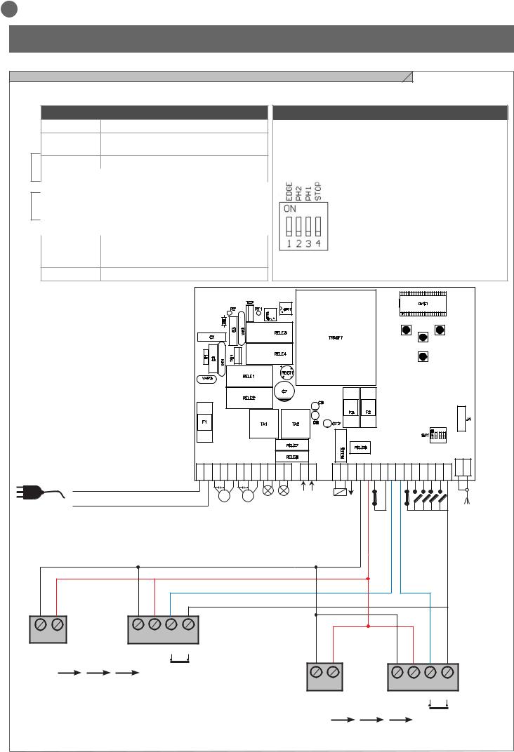
EN
4 - PRODUCT INSTALLATION
4.1 - Electrical connections
WARNING - Before making the connections, ensure that the control unit is not powered up.
M1
M2
POWER SUPPLY CONNECTOR AND MOTOR
L |
230 Vac (120 Vac) 50-60 Hz power supply phase |
N230 Vac (120 Vac) 50-60 Hz power supply neutral
L1 |
Motor phase |
|
|
L2 |
Motor phase |
COM |
Motor common |
L1 |
Motor phase |
L2 |
Motor phase |
COM |
Motor common |
COURTESY L. Courtesy light, 230 Vac (120 Vac) 100 W, output controllable also via radio ON-OFF command (radio channel 4 selecting fC.y. = 2, tC.y. = 0 )
FLASH |
Flashing light, 230 Vac (120 Vac) 40 W |
POWER SUPPLY CONNECTOR
Set on “ON” to disable inputs EDGE, PH2, PH1, STOP.
Eliminates the need to bridge the terminal board inputs.
WARNING - with the dip switch ON, the safety devices are disabled
1 = EDGE
2 = FOTO 2
3 = FOTO 1
4 = STOP
|
|
|
|
|
|
|
|
|
|
|
|
|
|
|
|
UP |
|
|
|
DOWN |
|
|
|
|
|
|
|
|
|
|
|
|
|
|
|
|
|
|
MENU |
|
|
|
|
|
|
|
|
|
|
|
|
|
|
|
|
|
|
|
|
SS |
|
|
|
L N L1 L2 |
COM |
L1 L2 |
COM |
COURTESY L. |
COURTESY L. |
FLASH |
FLASH |
24 Vac 24 Vac |
EL |
EL +24 Vdc |
GND |
+ 24 TX PH EDGE |
EDGE PH2 |
PH1 |
STOP |
OPEN |
CLOSE |
PED |
SS COM |
L |
M1 |
|
M2 |
|
|
|
|
|
OUTPUT Vac24 |
|
OUTPUT |
Vdc24 |
|
|
|
|
|
|
|
|
N |
|
|
|
|
|
|
|
|
|
|
|
|
|
|
|
|||||
|
|
|
|
|
|
|
|
|
|
|
|
|
|
|
|
|
|
|||
|
|
|
|
|
|
|
|
|
|
|
|
|
|
|
|
|
|
|
|
|
1 |
2 |
1 |
2 |
3 |
4 |
GND |
12/24 |
GND 12/24 |
COM OUT |
||
_ |
AC/DC |
||||
|
_ |
AC/DC |
|
||
|
|
|
|
|
NC |
TX PH2 RX
1 |
2 |
1 |
2 |
3 |
4 |
GND 12/24 |
GND 12/24 |
COM OUT |
|||
_ |
AC/DC |
_ |
AC/DC |
|
|
|
|
|
|
|
NC |
TX PH1 RX
18

EN
SAFETY AND CONTROL DEVICE CONNECTOR
24 Vac |
Accessories power 24 Vac, 1 A |
|
|
EL 12 Vac |
Electric lock output 12 Vac / 15 VA |
|
|
+24 Vdc |
Accessories power positive 24 Vdc, 500 mA |
|
|
GND |
Accessories power negative 24 Vdc, 500 mA |
|
|
+ 24 Vdc |
Power positive for photocells PH1, PH2; fototest selectable with parametert.p.h |
TX PHOTO |
|
EDGE |
Safety edge, ON/OFF NC or 8K2 contact between EDGE and EDGE (caution: when dip switch 1 is set to ON this disables the |
|
EDGE safety input) |
PH2 |
Photocells (opening) NC contact between PH2 and COM (caution: when dip switch 2 is set to ON this disables the PHOTO- |
|
CELL 2 safety input). The photocells trip at any time during automation opening, causing immediate shutdown of the motor; |
|
the automation continues opening on reset of the contact. During closing the photocell trips causing immediate shutdown of |
|
movement; the automation inverts movement to opening when the contact is reset. |
PH1 |
Photocells (closing) NC contact between PH1 and COM (caution: when dip switch 3 is set to ON this disables the PHOTO- |
|
CELL 1 safety input). The photocell trips at any time during automation closing, causing immediate shutdown of movement and |
|
inverting the direction of travel; this photocell is not enabled during opening. |
STOP |
STOP safety device, NC contact between STOP and COM (warning, with dip switch 4 ON the STOP safety device input is off) |
|
This input is classified as a safety device; the contact can be deactivated at any time, cutting out the automation system and |
|
disabling all functions, including Automatic Closure |
OPEN |
OPEN command NO contact between OPEN and COM |
|
Contact for the HOLD-TO-RUN function. The gate OPENS as long as the contact is held down |
CLOSE |
CLOSE command NO contact between CLOSE and COM |
|
Contact for the HOLD-TO-RUN function. The gate CLOSES as long as the contact is held down |
PED |
PEDESTRIAN command NO contact between PED and COM |
|
Used to open the gate partially, depending on the software setting |
SSSTEPPING command NO contact between SS and COM Open/Stop/Close/Stop command, or as set in the software
COM |
Common for the PH1, PH2, STOP, OPEN, CLOSE, PED and SS inputs |
|
|
SHIELD |
Antenna - sheath - |
|
|
SIGNAL |
Antenna - signal - |
4.2 - Display during normal operation
In “NORMAL OPERATING MODE”, i.e. when the system is powered up normally, the 3-figure LCD display shows the following status messages:
MESSAGES MEANING
--Gate closed or switch-on after shutdown
OP |
Gate opening |
CL |
Gate closing |
|
|
SO |
Gate stopped during opening |
|
|
SC |
Gate stopped during closure |
|
|
HA |
Gate stopped by external event |
|
|
oP |
Gate stopped without automatic reclosure |
|
|
Pe |
Gate in pedestrian opening position without automatic reclosure |
|
|
-tC |
Gate open with timed reclosure |
Flashing dash counting in progress |
|
|
Dash replaced by figures 0..9 countdown (last 10s) |
-tP |
Gate in pedestrian opening position with timed reclosure |
Flashing dash counting in progress |
|
|
Dash replaced by figures 0..9 countdown (last 10s) |
L-- |
Control unit ready for travel learning cycle |
LOP |
Learning opening |
|
|
LCL |
Learning closure |
19
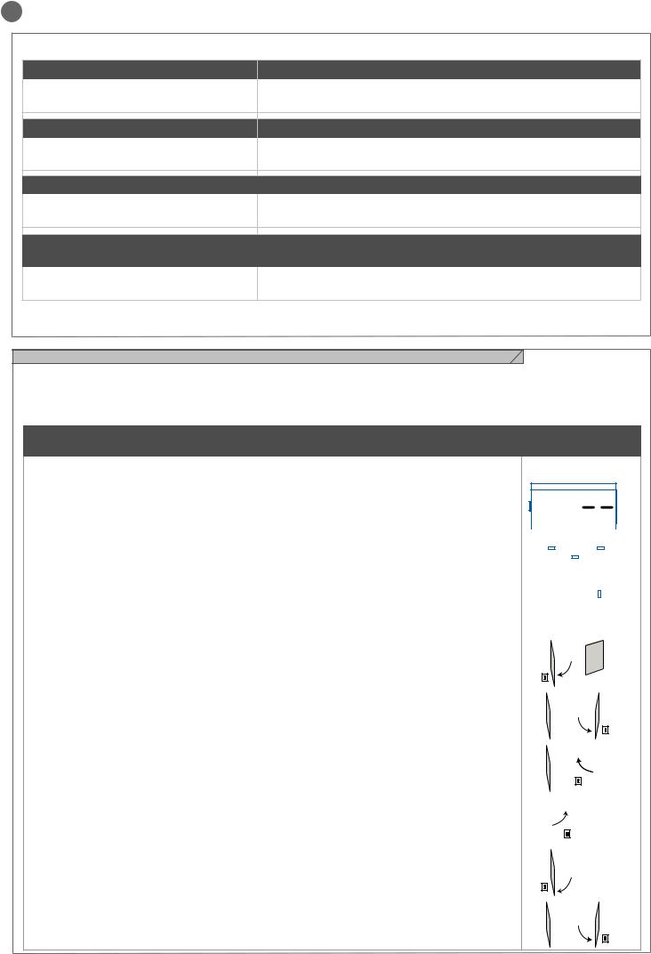
EN
Malfunctions
This section lists a number of malfunctions which may occur.
SURGE OVERLOAD ALARM |
The motor’s current drawdown has increased very quickly |
||
EFO |
1. |
Leaf impact with obstacle. |
|
2. |
Gate rubs during opening/closing |
||
|
|||
SAFETY EDGE ALARM |
The control unit has received a signal from the safety edge |
||
EED |
1. |
The safety edge has been pressed. |
|
|
|
||
2. |
The safety edge is not connected correctly. |
||
|
|||
PHOTOCELL ALARM |
Phototest fail outcome |
||
EPH |
1. |
Check the photocell connections. |
|
|
|
||
2. |
Check that the photocells are operating correctly. |
||
|
|||
ELECTRONIC OVERLOAD CUTOUT Motor not absorbing power |
|||
TRIPPED |
|
|
|
Eth |
1. |
Check the motor’s power drawdown. |
|
2. |
Check that the gate travels smoothly and that there are no obstacles. |
||
|
|||
After eliminating the cause of the alarm, to delete all errors simply press the “DOWN -” key or press the SS (STEPPING) command
The display returns to the normal screen.
4.3 -Autolearning of the travel stroke
The first time the control unit is powered up, an autolearning procedure must be carried out to acquire fundamental parameters such as the travel stroke length and deceleration points.
Press the + or - keys to view not only the status of the control unit, as
explained in the first table in point 4.2, but also the count of the ope- ning-closing operations performed. In the operation count display, thousands, displayed without dots, alternate with units, displayed with dots between them (e.g.: 50.000 = 50/0.0.0).
AUTOLEARNING OF THE TRAVEL STROKE AND MAIN PARAMETERS, WITH
PRESET DECELERATIONS
The deceleration intervals are as set in the menu, with the same percentage applied during opening and closing.
CAUTION: if manual programming of deceleration intervals is required, go to the next table
1. |
CAUTION! check that mechanical end stops (compulsory) are present and secure. The motors must |
|
|
|
|
|
|
|
|
|
|
|
|
|
|
|
|
|
|
|
|
|
|
|
|
|
|
|
|
|
|
|
|
|
|
|
|
|
|
|
|
||
always reach the mechanical end stop |
|
|
|
UP |
|
|
|
DOWN |
|||||||||||||
2. |
Move the gate manually to mid-travel. |
|
|
|
|
|
|
|
|
|
|
|
|
|
|
|
|
|
|
|
|
|
|
|
|
|
|
|
|
|
|
|
|
|
|
|
|
|
|
|
|
||
|
|
|
|
|
|
|
|
|
|
|
|
|
|
|
|
|
|
|
|
||
3. |
Press the pushbuttons UP + and MENU at the same time for at least 5 seconds until LOP is displayed, then |
|
|
|
|
|
|
MENU |
|
|
|
|
|
|
|
|
|
|
|
|
|
|
|
|
|
|
|
|
|
|
|
|
|
|
|
|
|
|
|
|
|
||
(if necessary) press DOWN (see figure). |
|
|
|
|
|
|
|
|
|
|
|
|
|
|
|
|
|
|
|
|
|
Ensure that motor M1 is activated first; otherwise, press DOWN -, turn the power off and invert connections |
|
|
|
|
|
|
|
|
|
|
|
|
|
|
|
|
|
|
|
|
|
M1 and M2. Repeat the procedure from step 3. |
|
|
|
|
|
|
|
|
|
|
|
|
|
|
|
|
|
|
|
|
|
|
|
|
|
|
|
|
|
|
SS |
|
|
|
|
|
|
|
|||||
If the first manoeuvre is NOT opening, press DOWN - to stop the self-learning process. Then press SS to |
|
|
|
|
|
|
|
|
|
|
|
|
|
|
|
|
|
|
|
|
|
restart acquisition: the leaf resumes movement in the correct direction. |
|
|
|
|
|
|
|
|
|
|
|
|
|
|
|
|
|
|
|
|
|
4. |
Motor M1 opens at low speed until it reaches the mechanical opening end stop. |
|
|
|
|
M1 |
|
|
M2 |
|
|
|
|
|
4 |
|
|||||
|
|
|
|
|
|
|
|
|
|
|
|
||||||||||
|
|
|
|
|
|
|
|
|
|
|
|
|
|
|
|
||||||
At precisely the time of reaching the mechanical opening end stop, press the SS command. |
|
|
|
|
|
|
|
|
|
|
|
|
|
|
|
|
|||||
|
|
|
|
|
|
|
|
|
|
|
|
|
|
|
|
|
|
|
|
||
Motor M2 starts automatically in opening mode. If motor M2 moves in closing, stop by pressing DOWN - and |
|
|
|
|
|
|
|
|
|
|
|
|
|
|
|
|
|
|
|
|
|
|
|
|
|
|
|
|
|
|
|
|
|
|
|
|
|
|
|
|
|
||
resume movement using SS (the leaf resumes movement in the correct direction) |
|
|
|
|
|
|
|
|
|
|
|
|
|
|
|
|
|
|
|
||
|
SS |
|
|
|
|
|
|
|
|
|
|
|
|
|
|
||||||
5. |
Motor M2 opens at low speed. At precisely the time of reaching the mechanical opening end stop, |
|
|
|
M1 |
|
|
M2 |
|
|
|
|
5 |
|
|||||||
|
|
|
|
|
|
|
|
|
|
||||||||||||
|
|
|
|
|
|
|
|
|
|
|
|
|
|
|
|
|
|
|
|
||
press the SS command. After a couple of seconds, motor M2 starts automatically in closing at full speed. |
|
|
|
|
|
|
|
|
|
|
|
|
|
|
|
|
|
|
|
|
|
|
|
|
|
|
|
|
|
|
|
|
|
|
|
|
|
|
|
|
|
|
|
|
|
|
|
|
|
|
|
|
|
|
|
|
|
|
|
|
|
|
|
||
|
|
|
|
|
|
|
|
|
|
|
|
|
|
|
|
|
|
|
|
||
|
|
|
|
|
|
|
|
|
|
|
|
|
|
SS |
|||||||
6. |
Precisely when motor M2 reaches the closed position, press the SS command. Motor M2 stops and |
|
|
|
M1 |
|
|
|
|
|
|
|
6 |
|
|||||||
|
|
|
|
M2 |
|
|
|
|
|||||||||||||
motor M1 starts in closing. |
|
|
|
|
|
|
|
|
|
|
|
|
|
|
|
|
|
|
|
|
|
|
|
|
|
|
|
|
|
|
|
|
|
|
|
|
|
|
|
|
|
||
|
|
|
|
|
|
|
|
|
|
|
|
|
|
|
|
|
|
|
|
||
|
|
|
|
|
|
|
|
|
|
|
|
|
|
|
|
|
|
|
|
||
|
|
|
|
|
|
|
|
SS |
|
|
|
|
|
|
|
|
|||||
7. Precisely when motor M1 reaches the closed position, press the SS command. Motor M1 stops and |
|
|
|
|
|
|
|
|
|
7 |
|
|
|
||||||||
|
|
|
M1 |
|
M2 |
|
|
|
|
|
|
||||||||||
restarts in opening. |
|
|
|
|
|
|
|
|
|
|
|
|
|
|
|
|
|
|
|
|
|
|
|
|
|
|
|
|
|
|
|
|
|
|
|
|
|
|
|
|
|
||
|
|
|
|
|
|
|
SS |
|
|
|
|
|
|
|
|
||||||
8. |
Precisely when motor M1 reaches the open position, press the SS command. Motor M1 stops and |
|
|
|
|
M1 |
|
|
|
|
|
|
|
|
8 |
|
|||||
|
|
|
|
|
|
M2 |
|
|
|
|
|
|
|
||||||||
motor M2 starts in opening. |
|
|
|
|
|
|
|
|
|
|
|
|
|
|
|
|
|
|
|
|
|
|
|
|
|
|
|
|
|
|
|
|
|
|
|
|
|
|
|
|
|
||
|
|
|
|
|
|
|
|
|
|
|
|
|
|
|
|
|
|
|
|||
|
|
|
|
|
|
|
|
|
|
|
|
|
|
|
|
|
|
|
|||
|
|
|
SS |
|
|
|
|
|
|
|
|
|
|
|
|
|
|
||||
9. |
Precisely when motor M2 reaches the open position, press the SS command. Motor M2 stops. |
|
|
|
M1 |
|
|
M2 |
|
|
|
9 |
|
||||||||
|
|
|
|
|
|
|
|
|
|
||||||||||||
|
|
|
|
|
|
|
|
|
|
|
|
|
|
|
|
|
|
|
|
||
|
|
|
|
|
|
|
|
|
|
|
|
|
|
|
|
|
|||||
|
|
|
|
|
|
|
|
|
|
|
|
|
|
SS |
|||||||
20
EN
10. Motors M1 and M2 resume closing according to the leaf offset values set in the menu, i.e. the gate closes |
|
M1 |
M2 |
|
10 |
|
|
||||
|
|
|
|
|
|
automatically according to the set travel. |
|
|
|
|
|
|
|
|
|
|
|
11. Run a number of opening, closing and stop manoeuvres, to check that the system is stable and there are no assembly defects.
All main parameters are configured as default by the control unit. To personalise installation, go to the next step in paragraph 4.4. If torque
is not sufficient to move the leaf, delete the deceleration intervals from the menu [LSI=0].
AUTOLEARNING OF THE TRAVEL STROKE AND MAIN PARAMETERS, WITH
CUSTOMISED DECELERATIONS
Deceleration intervals can be personalised by the user, according to the procedure below.
1.CAUTION! check that mechanical end stops (compulsory) are present and secure. The motors must always reach the mechanical end stop
2.Move the gate manually to mid-travel.
|
|
|
|
UP |
|
|
|
|
|
|
|
DOWN |
|||||||||||
3. CAUTION: enter the main menu to set the parameterLSI = p as per the table in paragraph 4.4 |
|
|
|
|
|
|
|
|
|
|
|||||||||||||
|
|
|
|
|
|
|
|
|
|
|
|
|
|
|
|
|
|
|
|
|
|
|
|
4. Press the pushbuttons UP + and MENU at the same time for at least 5 seconds until LOP is displayed, then |
|
|
|
|
|
|
|
|
|
|
|
|
|
|
|
|
|
|
|
|
|
|
|
|
|
|
|
|
|
|
|
|
|
|
|
|
|
|
|
|
|
|
|
|
|
|
|
|
|
|
|
|
|
|
MENU |
|
|
|
|
|
|
|
|
|
|
|
|||||
(if necessary) press DOWN (see figure). |
|
|
|
|
|
|
|
|
|
|
|
|
|
|
|
|
|
|
|||||
|
|
|
|
|
|
|
|
|
|
|
|
|
|
|
|
|
|
|
|
|
|
|
|
Ensure that motor M1 opens first; otherwise, press DOWN -, turn the power off and invert connections M1 and |
|
|
|
|
|
|
|
|
|
|
|
|
|
|
|
|
|
|
|
|
|
|
|
M2. Repeat the procedure from step 4. |
|
|
|
|
|
|
|
|
|
|
|
|
|
|
|
|
|
|
|
|
|
|
|
If the first manoeuvre is NOT opening, press DOWN - to stop the self-learning process. Then press SS to |
|
|
|
|
|
|
|
|
|
|
|
|
|
|
|
|
|
|
|
|
|
|
|
|
|
|
|
|
|
|
|
|
|
|
|
|
|
SS |
|
||||||||
restart acquisition: the leaf resumes movement in the correct direction. |
|
|
|
|
|
|
|
|
|
|
|
|
|
|
|
|
|
|
|
|
|
|
|
5. Motor M1 opens at low speed until it reaches the mechanical opening end stop. |
|
|
M1 |
|
|
M2 |
|
|
|
|
|
|
|
|
5 |
|
|||||||
|
|
|
|
|
|
|
|
|
|
|
|
|
|||||||||||
At precisely the time of reaching the mechanical opening end stop, press the SS command. |
|
|
|
|
|
|
|
|
|
|
|
|
|
|
|
|
|
|
|
||||
Motor M2 starts automatically in opening mode. If motor M2 moves in closing, stop by pressing DOWN - and |
|
|
|
|
|
|
|
|
|
|
|
|
|
|
|
|
|
|
|
|
|
|
|
resume movement using SS (the leaf resumes movement in the correct direction) |
SS |
|
|
|
|
|
|
|
|
|
|
|
|
|
|
|
|
|
|||||
|
|
|
|
|
|
|
|
|
|
|
|
|
|
|
|
|
|
||||||
6. Motor M2 opens at low speed. At precisely the time of reaching the mechanical opening end stop. |
|
|
M1 |
|
M2 |
|
|
|
|
|
6 |
|
|
||||||||||
|
|
|
|
|
|
|
|
|
|
||||||||||||||
After a couple of seconds, motor M2 starts automatically in closing at full speed. |
|
|
|
|
|
|
|
|
|
|
|
|
|
|
|
|
|
|
|
|
|
|
|
|
|
|
|
|
|
|
|
|
|
|
|
|
|
|
|
|
|
|
|
|
|
||
|
|
|
|
|
|
|
|
|
|
|
|
|
|
|
|
|
|
|
|
|
|||
|
|
|
|
|
|
|
|
|
|
|
|
|
|
|
|
|
|
|
|
|
|||
|
|
|
|
|
|
|
|
|
|
|
|
|
|
SS |
|||||||||
7. On reaching the point where motor M2 closing deceleration is required, press SS. M2 motor move- |
|
|
M1 |
|
M2 |
|
|
|
|
|
7 |
|
|
||||||||||
|
|
|
|
|
|
|
|
|
|
||||||||||||||
ment continues at low speed. |
|
|
|
|
|
|
|
|
|
|
|
|
|
|
|
|
|
|
|
||||
|
|
|
|
|
|
|
|
|
|
|
|
|
|
|
|
|
|
|
|
|
|
|
|
|
|
|
|
|
|
|
|
|
|
|
|
|
|
|
|
|
|
|
|
|
|
||
|
|
|
|
|
|
|
|
|
|
|
|
|
|
SS |
|||||||||
8. Precisely when motor M2 reaches the closed position, press the SS command. Motor M2 stops and |
|
|
M1 |
|
|
|
|
|
|
|
8 |
|
|
||||||||||
|
|
|
M2 |
|
|
|
|
|
|
|
|||||||||||||
motor M1 starts in closing. |
|
|
|
|
|
|
|
|
|
|
|
|
|
|
|
|
|
|
|
|
|
|
|
|
|
|
|
|
|
|
|
|
|
|
|
|
|
|
|
|
|
|
|
|
|
||
|
|
|
|
|
|
|
|
|
|
|
|
|
|
|
|
|
|
|
|
|
|||
|
|
|
|
|
|
|
|
|
|
|
|
|
|
|
|
|
|
|
|
|
|||
|
|
|
|
|
|
|
SS |
|
|
|
|
|
|
|
|
|
|
|
|||||
9. On reaching the point where motor M1 closing deceleration is required, press SS. M1 motor move- |
|
|
|
|
|
|
|
|
|
|
|
|
9 |
|
|||||||||
|
|
M1 |
|
M2 |
|
|
|
|
|
|
|||||||||||||
ment continues at low speed. |
|
|
|
|
|
|
|
|
|
|
|
|
|
|
|
|
|
|
|
|
|
|
|
|
|
|
|
|
|
|
|
|
|
|
|
|
|
|
|
|
|
|
|
|
|
||
|
SS |
|
|
|
|
|
|
|
|
|
|
|
|
|
|
|
|
|
|||||
10. Precisely when motor M1 reaches the closed position, press the SS command. Motor M1 stops and |
|
|
|
|
|
|
|
|
10 |
|
|
||||||||||||
|
|
M1 |
|
|
M2 |
|
|
|
|
|
|
||||||||||||
restarts in opening. |
|
|
|
|
|
|
|
|
|
|
|
|
|
|
|
|
|
|
|
|
|
|
|
|
|
|
|
|
|
|
|
|
|
|
|
|
|
|
|
|
|
|
|
|
|
|
|
|
|
|
|
SS |
|
|
|
|
|
|
|
|
|
|
|
|
|
|
|
|
|
||
11. On reaching the point where motor M1 opening deceleration is required, press SS. M1 motor move- |
|
|
|
|
|
|
|
|
|
|
|
11 |
|||||||||||
|
|
M1 |
|
M2 |
|
|
|
|
|
|
|||||||||||||
ment continues at low speed. |
|
|
|
|
|
|
|
|
|
|
|
|
|
|
|
|
|
|
|
|
|
|
|
|
|
|
|
|
|
|
|
|
|
|
|
|
|
|
|
|
|
|
|
|
|||
|
SS |
|
|
|
|
|
|
|
|
|
|
|
|
|
|
|
|
|
|||||
12. Precisely when motor M1 reaches the open position, press the SS command. Motor M1 stops and |
|
|
M1 |
|
|
|
|
|
|
|
|
12 |
|||||||||||
|
|
|
M2 |
|
|
|
|
|
|
||||||||||||||
motor M2 starts in opening. |
|
|
|
|
|
|
|
|
|
|
|
|
|
|
|
|
|
|
|
|
|
|
|
|
|
|
|
|
|
|
|
|
|
|
|
|
|
|
|
|
|
|
|
|
|||
|
|
|
|
|
|
|
|
|
|
|
|
|
|
|
|
|
|
|
|
|
|||
|
|
|
|
|
|
|
|
|
|
|
|
|
|
|
|
|
|
|
|
|
|||
|
SS |
|
|
|
|
|
|
|
|
|
|
|
|
|
|
|
|
|
|||||
13. On reaching the point where motor M2 opening deceleration is required, press SS. M2 motor move- |
|
|
M1 |
|
M2 |
|
|
|
13 |
|
|||||||||||||
|
|
|
|
|
|
|
|
|
|||||||||||||||
ment continues at low speed. |
|
|
|
|
|
|
|
|
|
|
|
|
|
|
|
|
|
|
|||||
|
|
|
|
|
|
|
|
|
|
|
|
|
|
|
|
|
|
|
|
|
|
|
|
|
|
|
|
|
|
|
|
|
|
|
|
|
|
|
|
|
|||||||
|
|
|
|
|
|
|
|
|
|
|
|
|
|
SS |
|||||||||
14. Precisely when motor M2 reaches the open position, press the SS command. Motor M2 stops. |
|
|
M1 |
|
M2 |
|
|
|
14 |
|
|||||||||||||
|
|
|
|
|
|
|
|
|
|||||||||||||||
|
|
|
|
|
|
|
|
|
|
|
|
|
|
|
|
|
|||||||
|
|
|
|
|
|
|
|
|
|
|
|
|
|
SS |
|||||||||
15. M1 and M2 resume closing according to the offset parameter entered in the menu, i.e. the gate closes |
|
|
M1 |
|
M2 |
|
|
|
|
|
15 |
||||||||||||
|
|
|
|
|
|
|
|
||||||||||||||||
automatically according to the set travel. |
|
|
|
|
|
|
|
|
|
|
|
|
|
|
|
|
|
|
|
|
|
|
|
|
|
|
|
|
|
|
|
|
|
|
|
|
|
|
|
|
|
|
|
|
|
|
|
16. Run a number of opening, closing and stop manoeuvres, to check that the system is stable and there are no assembly defects.
All main parameters are configured as default by the control unit. To personalise installation, go to the next step in paragraph 4.4.
21
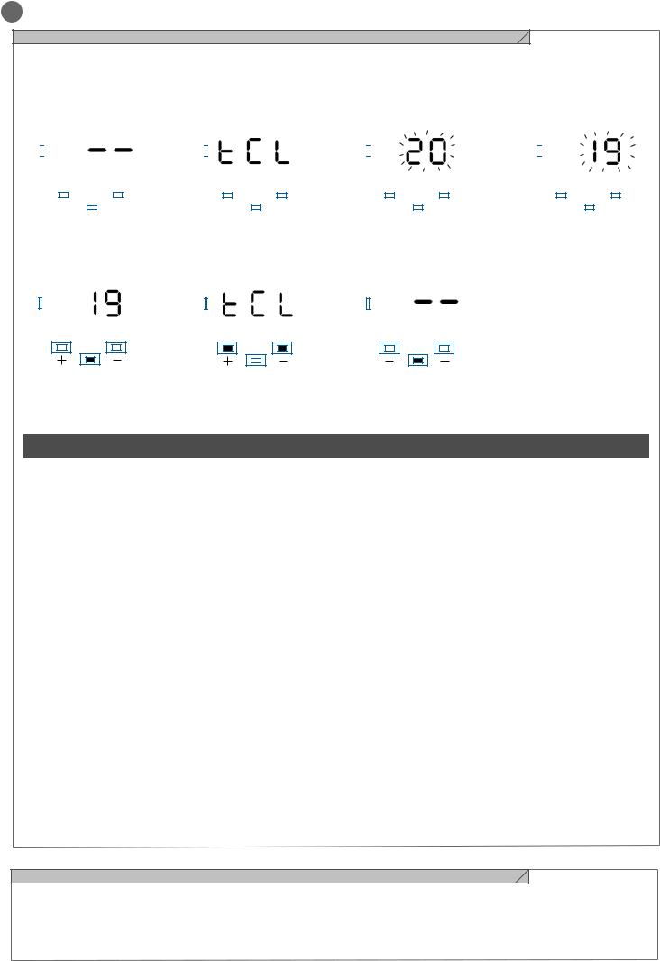
EN
4.4 - Customising the system - BASIC MENU
If necessary, users may select a BASIC MENU which allows modification of the control unit’s basic parameters. To select the BASIC MENU proceed as described below.
Exampling of modifying a BASIC MENU parameter
WARNING: to be certain of accessing the NORMAL OPERATION display state, the starting point for accessing the BASIC MENU, press the MENU key twice
|
|
|
|
|
|
|
|
|
|
|
|
|
|
|
|
|
|
|
|
|
|
|
|
|
|
|
|
|
|
|
|
|
|
|
|
|
|
|
|
|
|
|
|
|
|
|
|
|
|
|
|
|
|
|
|
|
|
|
|
|
|
|
|
|
|
|
|
|
|
|
|
|
|
|
|
|
|
|
|
|
|
|
|
|
|
|
|
|
|
|
|
|
|
|
|
|
|
|
|
|
|
|
|
|
|
|
|
|
|
|
|
|
|
|
|
|
|
|
|
|
|
|
|
|
|
|
|
|
|
|
|
|
|
|
|
|
|
|
|
|
|
|
|
|
|
|
|
|
|
|
|
|
|
|
|
|
|
|
|
|
|
|
|
|
|
|
|
|
|
|
|
|
|
|
|
|
|
|
|
|
|
|
|
|
|
|
|
|
|
|
|
|
|
|
|
|
|
|
|
|
|
|
|
|
|
|
|
|
|
|
|
|
|
|
|
|
|
|
|
|
|
|
|
|
|
|
|
|
|
|
|
|
|
|
|
|
|
|
|
|
|
|
|
|
|
|
|
|
|
|
|
|
|
|
|
|
|
|
|
|
|
|
|
|
|
|
|
|
|
|
|
|
|
|
|
|
|
|
|
|
|
|
UP |
|
|
|
|
|
DOWN |
|
|
UP |
|
|
|
DOWN |
|
|
|
UP |
|
|
|
|
|
DOWN |
|
|
|
UP |
|
|
|
DOWN |
|||||||||||||||||||||
|
|
|
|
|
|
|
MENU |
|
|
|
|
|
|
|
|
|
|
|
MENU |
|
|
|
|
|
|
|
|
|
|
|
MENU |
|
|
|
|
|
|
|
|
|
|
|
MENU |
|
|
|
|
||||||||
|
|
|
|
|
|
|
|
|
|
|
|
|
|
|
|
|
|
|
|
|
|
|
|
|
|
|
|
|
|
|
|
|
|
|
|
|
|
|
|
|
|
|
|
||||||||||||
|
|
|
|
|
|
|
|
|
|
|
|
|
|
|
|
|
|
|
|
|
|
|
|
|
|
|
|
|
|
|
|
|
|
|
|
|
|
|
|
|
|
|
|
||||||||||||
|
|
|
|
|
|
|
|
|
|
|
|
|
|
|
|
|
|
|
|
|
|
|
|
|
|
|
|
|
|
|
|
|
|
|
|
|
|
|
|
|
|
|
|
|
|
|
|
|
|
|
|
|
|
|
|
|
|
|
|
|
|
|
|
|
|
|
|
|
|
|
|
|
|
|
|
|
|
|
|
|
|
|
|
|
|
|
|
|
|
|
|
|
|
|
|
|
|
|
|
|
|
|
|
|
|
|
|
|
|
|
|
Press the MENU key for 1 se- |
After accessing the BASIC |
To access the value modifica- |
||||||
cond to access the basic menu. |
MENU, press the + and – keys |
tion function, press the MENU |
||||||
|
|
|
to scroll through the functions. |
key for 1 second, until the va- |
||||
|
|
|
|
|
|
lue starts to flash quickly. |
||
|
|
|
|
|
|
|
|
|
|
|
|
|
|
|
|
|
|
|
|
|
|
|
|
|
|
|
|
|
|
|
|
|
|
|
|
Press the + and – keys to to modify the value.
UP DOWN
MENU
Press the MENU key for 1 second to display the parameter in order to save the modified value, or MENU quickly to quit the function without saving.
UP DOWN
MENU
Press the + and – keys to scroll through the functions to modify other parameters.
UP DOWN
MENU
Press the MENU key quickly to quit the menu.
|
|
|
|
|
|
|
|
|
|
PARAMETERS |
|
DESCRIPTION |
DEFAULT |
MIN |
MAX |
UNIT |
|
|
|
CONFIGURATION |
||||||
1 |
TCL |
Automatic reclosing time (0 = disabled) |
20 |
0 |
900 |
s |
||
2 |
ttr |
Reclosing after transit time (0 = disabled) |
0 |
0 |
30 |
s |
||
3 |
SEI |
Obstacle sensitivity |
0 |
0 |
100 |
% (steps |
||
(0 = disabled) |
of 1) |
|||||||
|
|
|
|
|
||||
4 |
trq |
Motor force (torque at operating speed) |
100 |
10 |
100 |
% (steps |
||
of 10) |
||||||||
|
|
|
|
|
|
|
||
5 |
SSL |
Deceleration mode |
|
|
|
|
||
0 |
= deceleration 1/3 (slow) |
0 |
0 |
1 |
|
|||
|
|
1 |
= deceleration 2/3 (fast) |
|
|
|
|
|
|
|
SS configuration: |
|
|
|
|
||
|
|
0 |
= Normal (OP-ST-CL-ST-OP-ST…) |
|
|
|
|
|
6 |
SbS |
1 |
= Alternate STOP (OP-ST-CL-OP-ST-CL…) |
0 |
0 |
4 |
|
|
2 |
= Alternate (OP-CL-OP-CL…) |
|
||||||
|
|
|
|
|
|
|||
|
|
3 |
= Apartment block – timer |
|
|
|
|
|
|
|
4 |
= Apartment block with immediate reclosing |
|
|
|
|
|
7 |
bLt |
Response after black out |
|
|
|
|
||
0 |
= no action, as per before failure |
0 |
0 |
1 |
|
|||
|
|
1 |
= Closing |
|
|
|
|
|
8 |
SST |
Soft start (slow start-up) |
|
|
|
|
||
0 |
= disabled |
0 |
0 |
1 |
|
|||
|
|
1 |
= enabled |
|
|
|
|
|
9 |
dLY |
Second leaf delay |
2 |
0 |
300 |
s |
||
10 |
LSI |
Deceleration range |
|
|
|
% (steps |
||
P = personalised from learning cycle |
15 |
0 |
100 |
|||||
of 1) |
||||||||
|
|
0...100% = travel percentage |
|
|
|
|||
|
|
|
|
|
|
|||
11 |
ASL |
Anti-slip: extension of set work time (useful in areas |
0 |
0 |
300 |
s |
||
subject to strong winds) |
||||||||
|
|
Number of motors |
|
|
|
|
||
|
n |
1 |
= 1 motor |
|
|
|
|
|
12 |
nMt |
2 |
= 2 motors |
1 |
1 |
2 |
|
|
|
|
|
|
|
|
|||
|
|
|
|
|
|
|
|
|
4.5 - Connecting the radio receiver
Connect the radio receiver, removing the plastic cover and taking care to position it as shown in the diagram in point 2.1.
For programming, follow the receiver instructions, remembering that
the 4 outputs which can be activated are:
OUTPUT 1 = STEP BY STEP, OUTPUT 2 = PEDESTRIAN, OUTPUT 3 = OPEN, OUTPUT 4 = CLOSE.
22

EN
5 - TESTING AND COMMISSIONING THE AUTOMATION SYSTEM
The system must be tested by a qualified technician, who must perform the tests required by the relevant standards in relation to the risks present, to check that the installation complies with the
5.1 - Testing
relevant regulatory requirements, especially the EN12445 standard which specifies the test methods for gate and door automation systems.
All system components must be tested following the procedures described in their respective operator’s manuals;
ensure that the recommendations in Chapter 1 - Safety Warnings - have been complied with;
check that the gate or door is able to move freely once the automation system has been released and is well balanced, meaning that it will remain stationery when released in any position;
check that all connected devices (photocells, sensitive edges,
emergency buttons, etc.) are operating correctly by performing gate or door opening, closing and stop tests using the connected control devices (transmitters, buttons or switches);
perform the impact measurements as required by the EN12445 standard, adjusting the control unit’s speed, motor force and deceleration functions if the measurements do not give the required results, until the correct setting is obtained.
5.2 - Commissioning
Once all (and not just some) of the system devices have passed the testing procedure, the system can be commissioned;
the system’s technical dossier must be produced and kept for 10 years. It must contain the electrical wiring diagram, a drawing or photograph of the system, the analysis of the risks and the solutions adopted to deal with them, the manufacturer’s declaration of conformity for all connected devices, the operator’s manual for every device and the system maintenance plan;
fix a dataplate with the details of the automation, the name of the person who commissioned it, the serial number and year of construction and the CE marking on the gate or door;
also fit a sign specifying the procedure for releasing the system by hand;
draw up the declaration of conformity, the instructions and precautions for use for the end user and the system maintenance plan and consign them to the end user;
ensure that the user has fully understood how to operate the system in automatic, manual and emergency modes;
the end user must also be informed in writing about any risks and hazards still present;
WARNING - after detecting an obstacle, the gate or door stops during its opening travel and automatic closure is disabled; to restart operation, the user must press the control button or use the transmitter.
23

EN
6 - FURTHER DETAILS - ADVANCED MENU
The ADVANCED MENU allows the system to be further customised |
down for 5 seconds |
by modifying parameters not accessible from the basic menu |
To modify ADVANCED MENU parameters, proceed as described |
|
|
To access the ADVANCED menu, press the MENU key and hold it |
for the BASIC MENU |
|
|
|
|
|
|
|
|
|
|
PARAMETERS |
|
DESCRIPTION |
DEFAULT |
MIN |
MAX |
UNIT |
|
|
|
CONFIGURATION |
||||||
|
EL.F. |
Electric brake |
|
|
|
x 0.01s |
||
1 |
0 |
= disabled |
0 |
0 |
100 |
|||
(steps of 5) |
||||||||
|
|
1 |
= enabled |
|
|
|
|
|
|
SP.h. |
PHOTO1 response on start-up from closed |
|
|
|
|
||
2 |
0 |
= PHOTO1 check |
1 |
0 |
1 |
|
||
|
|
1 |
= the gate also opens if PHOTO1 is engaged |
|
|
|
|
|
|
Ph.2. |
PHOTO2 response |
|
|
|
|
||
3 |
0 |
= Enabled in opening and closing OP/CL |
0 |
0 |
1 |
|
||
|
|
1 |
= Enabled only in opening OP |
|
|
|
|
|
|
|
Photo device test |
|
|
|
|
||
|
tP.h. |
0 |
= disabled |
|
|
|
|
|
4 |
1 |
= PHOTO1 enabled |
0 |
0 |
3 |
|
||
|
|
2 |
= PHOTO1 enabled |
|
|
|
|
|
|
|
3 |
= PHOTO1 and PHOTO2 enabled |
|
|
|
|
|
|
n |
Type of edge |
|
|
|
|
||
5 |
0 |
= contact (NC) |
0 |
0 |
1 |
|
||
ed.M. |
|
|||||||
|
|
1 |
= resistive (82k) |
|
|
|
|
|
|
|
Edge intervention mode |
|
|
|
|
||
6 |
iE.D. |
0 |
= intervenes only on closing with inversion of direction |
0 |
0 |
1 |
|
|
1 |
= stops automation (on opening and closing) and releases |
|
||||||
|
|
the obstacle (short inversion) |
|
|
|
|
||
|
tE.D. |
Edge test |
|
|
|
|
||
7 |
0 |
= disabled |
0 |
0 |
1 |
|
||
|
|
1 |
= enabled |
|
|
|
|
|
8 |
LP.o. |
Pedestrian opening |
30 |
0 |
100 |
% (steps |
||
of 1) |
||||||||
9 |
TP.C. |
Automatic reclosing time from pedestrian (0 = disabled) |
20 |
0 |
900 |
s |
||
|
FP.r. |
Flashing light output configuration |
|
|
|
|
||
10 |
0 |
= Steady |
1 |
0 |
1 |
|
||
|
|
1 |
= Flashing |
|
|
|
|
|
11 |
tP.r. |
Pre-flash time |
0 |
0 |
10 |
s |
||
(0 = disabled) |
||||||||
|
|
Courtesy light configuration |
|
|
|
|
||
|
|
0 |
= At end of manoeuvre, lit for time TCY |
|
|
|
|
|
12 |
FC.Y. |
1 |
= Lit if gate is not closed + duration TCY |
0 |
0 |
4 |
|
|
2 |
= Lit if courtesy light timer (TCY) not elapsed |
|
||||||
|
|
3 |
= Gate open indicator on/off |
|
|
|
|
|
|
|
4 |
= Gate open indicator proportional flashing |
|
|
|
|
|
13 |
tC.Y. |
Courtesy light duration |
0 |
0 |
900 |
s (steps |
||
of 10s) |
||||||||
|
dE.A. |
Hold-to-run |
|
|
|
|
||
14 |
0 |
= disabled |
0 |
0 |
1 |
|
||
|
|
1 |
= enabled |
|
|
|
|
|
|
|
Cycle threshold for assistance request. On reaching the set |
|
|
|
|
||
15 |
se.r. |
threshold the subsequent cycles will be performed with |
0 |
0 |
100 |
x 1000 |
||
quick flashing (only if FPr is active). |
cycles |
|||||||
|
|
(0 = disabled) |
|
|
|
|
||
|
|
Enabled in continuous flashing mode for assistance requests |
|
|
|
|
||
16 |
se.f. |
(function only enabled when gate is closed). |
0 |
0 |
1 |
|
||
0 |
= disabled |
|
||||||
|
|
1 |
= enabled |
|
|
|
|
|
17 |
HA.o. |
Water hammer on opening |
0 |
0 |
100 |
*100ms |
||
0 |
= disabled |
|||||||
18 |
HA.c. |
Water hammer on closing |
0 |
0 |
100 |
*100ms |
||
0 |
= disabled |
|||||||
|
n |
Interval for maintaining hydraulic motor pressure |
|
|
|
|
||
|
0 |
= disabled |
|
|
|
|
||
19 |
mp.r. |
from 1 to 480 enabled as follows: 1 = 1 min. ON and 1 min |
0 |
0 |
480 |
minutes |
||
|
|
OFF, 2 = 1 min. ON and 2 min. OFF, ... |
|
|
|
|
||
20 |
de.f. |
Reset to default values |
|
|
|
|
||
To set the default values: 1) access the advanced programming function; 2) select the “dEf” parameter”; 3) activate the modification mode (“0” on display”); 4) accept the modification (press “MENU”
and hold it down). A countdown should now appear: d80,d79...,d01 down to “don“. Release the key when finished.
24

EN
7 - INSTRUCTIONS AND WARNINGS FOR THE END USER
Key Automation S.r.l. produces systems for the automation of gates, garage doors, automatic doors, roller blinds and car-park and road barriers. However, Key Automation is not the manufacturer of your complete automation system, which is the outcome of the analysis, assessment, choice of materials and installation work of your chosen installer. Every automation system is unique, and only your installer has the experience and skill required to produce a safe, reliable, durable system tailored to your needs, and above all that complies with the relevant regulatory standards. Although your automation system complies with the regulation safety level, this does not rule out the presence of “residual risk”, meaning the possibility that hazards may occur, usually due to reckless or even incorrect use. We would therefore like to give you some advice for the correct use of the system:
•before using the automation system for the first time, have the installer explain the potential causes of residual risks to you;
•keep the manual for future reference, and pass it on to any new owner of the automation system;
•reckless use and misuse of the automation system may make it dangerous: do not operate the automation system with people, animal or objects within its range of action;
•a properly designed automation system has a high level of safety, since its sensor systems prevent it from moving with people or obstacles present so that its operation is always predictable and safe.
However, as a precaution children should not be allowed to play close to the automation system, and to prevent involuntary activation, remote controls must not be left within their reach;
•as soon as any system malfunction is noticed, disconnect the electricity supply and perform the manual release procedure. Never attempt repairs on your own; call in your installation engineer. In the meantime the door or gate can be operated without automation once the geared motor has been released using the release key supplied with the system. In the event of safety devices out of service arrange for repairs to the automation immediately;
•in the event of malfunctions or power failures: while waiting for the engineer to come (or for the power to be restored if your system is not equipped with buffer batteries), the door or gate can be used just like any non-automated installation. To do this, the manual release procedure must be carried out;
•manual release and operation: first bear in mind that the release procedure can only be carried out with the door or gate stationery.
•Maintenance: Like any machine, your automation system needs regular periodic maintenance to ensure its long life and total safety. Arrange a periodic maintenance schedule with your installation engineer. Key Automation recommends that maintenance checks should be carried out every six months for normal domestic use, but this interval may vary depending on the level of use. Any inspection, maintenance or repair work must only be carried out by qualified staff.
•Never modify the automation system or its programming and setup parameters: this is the responsibility of your installation engineer.
•Testing, routine maintenance and any repairs must be recorded by the person who performs them and the documents must be conserved by the system’s owner.
The only procedures you are capable of, and which you are recommended to perform, are cleaning of the photocell glass and removal of any leaves or stones that may obstruct the automation system.
To prevent anyone from activating the gate or door, release the automation system before starting. Clean only with a cloth dipped in a little water.
At the end of its useful life, the automation system must be dismantled by qualified personnel, and the materials must be recycled or disposed of in compliance with the legislation locally in force.
If after some time your remote control seems to have become less effective, or stops operating completely, the battery may be flat (depending on the level of use, this may take from several months up to more than a year). You will realise this because the transmission confirmation light does not come on, or only lights up for a very short time.
Batteries contain pollutants: do not dispose of them with normal waste but follow the methods specified by the local regulations.
Thank you for choosing Key Automation S.r.l.; please visit our Internet site www.keyautomation.it for further information.
25

FR
TABLE DES MATIÈRES
1 |
|
|
|
|
|
|
Consignes de sécurité |
page. 27 |
|||
|
|
|
|||
2 |
|
|
|
|
|
|
Présentation du produit |
page. 28 |
|||
|
|
|
|||
2.1 |
Description de la logique de commande |
page. 28 |
|||
2.2 |
Description des branchements |
page. 28 |
|||
2.3 |
Modèles et caractéristiques techniques |
page. 28 |
|||
2.4 |
Liste des câbles nécessaires |
page. 29 |
|||
3 |
|
|
|
|
|
|
Vérifications préalables |
page. 29 |
|||
|
|
|
|||
4 |
|
|
|
|
|
|
Installation du produit |
page. 30 |
|||
|
|
|
|||
4.1 |
Branchements électriques |
page. 30 |
|||
4.2 |
Visualisation en mode normal |
page. 31 |
|||
4.3 |
Autoapprentissage de la course |
page. 32 |
|||
4.4 |
Personnalisation de l’installation-MENU DE BASE |
page. 34 |
|||
4.5 |
Branchement du récepteur radio |
page. 34 |
|||
5 |
|
|
|
|
|
|
Réception et mise en service |
page. 35 |
|||
|
|
|
|||
5.1 |
Réception |
page. 35 |
|||
5.2 |
Mise en service |
page. 35 |
|||
6 |
|
|
|
|
|
|
Approfondissements - MENU AVANCÉ |
page. 36 |
|||
|
|
|
|||
7 |
|
|
|
|
|
|
|
Instructions et avertissements |
page. 37 |
||
|
|
|
|||
|
|
|
destinés à l’utilisateur final |
|
|
8 |
|
|
|
|
|
|
|
Déclaration CE de conformité |
page. 87 |
||
|
|
|
|||
26

FR
1 - CONSIGNES DE SÉCURITÉ
ATTENTION – pour la sécurité des personnes, il est important de respecter ces instructions et de les conserver pour pouvoir les consulter ultérieurement.
Lire attentivement les instructions avant d’effectuer l’installation.
La conception et la fabrication des dispositifs qui composent le produit et les informations contenues dans ce guide respectent les normes de sécurité en vigueur. Néanmoins, une installation et une programmation erronées peuvent causer de graves blessures aux personnes qui exécutent le travail et à celles qui utiliseront l’installation. C’est pourquoi il est important, durant l’installation, de suivre scrupuleusement toutes les instructions fournies dans ce guide.
Ne pas effectuer l’installation en cas de doute, de quelque nature que ce soit, et, au besoin, demander des éclaircissements au service après-vente de Key Automation.
Pour la législation européenne, la réalisation d’une porte ou d’un portail automatique doit respecter les normes prévues par la directive 2006/42/CE (directive Machines) et, en particulier, les normes EN 12445, EN 12453, EN 12635 et EN 13241-1, qui permettent de déclarer la conformité de l’automatisme.
C’est pourquoi le branchement définitif de l’automatisme au réseau électrique, la réception de l’installation, sa mise en service et la maintenance périodique doivent être confiés à du personnel qualifié et spécialisé qui interviendra selon les instructions fournies dans la section « Réception et mise en service de l’automatisme ».
De plus, il devra se charger de procéder aux essais prévus en fonction des risques présents et vérifier le respect de toutes les prescriptions des lois, normes et règlements : en particulier, le respect de toutes les exigences de la norme EN 12445 qui définit les méthodes d’essai per la vérification des automatismes pour portes et portails.
ATTENTION - Avant de commencer l’installation, effectuer les analyses et vérifications suivantes:
vérifier que chacun des dispositifs destinés à l’automatisme est adapté à l’installation à réaliser. À ce sujet, contrôler tout particulièrement les données indiquées dans le chapitre « Caractéristiques techniques ». Ne pas effectuer l’installation si ne serait-ce qu’un seul de ces dispositifs n’est pas adapté à ce type d’utilisation;
vérifier que les dispositifs présents dans le kit sont suffisants pour garantir la sécurité de l’installation et son bon fonctionnement;
effectuer l’analyse des risques, qui doit aussi comprendre la liste des exigences essentielles de sécurité contenues dans l’annexe I de la directive Machines, en indiquant les solutions adoptées. L’a- nalyse des risques est l’un des documents qui constituent le dossier technique de l’automatisme. Ce dernier doit être rédigé par un installateur professionnel.
Compte tenu des situations de risque qui peuvent se présenter durant les phases d’installation et d’utilisation du produit, il est nécessaire d’installer l’automatisme en respectant les consignes suivantes:
Ne pas apporter de modifications à une quelconque partie de l’automatisme, en dehors de celles qui sont prévues dans ce guide. Ce type d’interventions ne peut que causer des problèmes de fonctionnement. Le constructeur décline toute responsabilité en cas de dommages dérivant de produits modifiés de manière arbitraire;
Il faut faire en sorte que les pièces des composants de l’automatisme ne soient jamais plongées dans l’eau ni dans d’autres substances liquides. Durant l’installation, éviter que des liquides puissent pénétrer à l’intérieur des dispositifs présents;
Si des substances liquides pénètrent à l’intérieur des pièces des composants de l’automatisme, débrancher immédiatement l’alimentation électrique et s’adresser au service après-vente Key Automation. L’utilisation de l’automatisme dans ces conditions peut être source de danger;
Ne pas mettre les différents composants de l’automatisme à proximité de sources de chaleur et ne pas les exposer à des flammes libres. Ces actions peuvent les endommager et causer des problèmes de fonctionnement, un incendie ou des dangers;
Toutes les opérations qui nécessitent l’ouverture de la coque de protection des différents composants de l’automatisme doivent s’effectuer avec la logique de commande débranchée de l’alimentation électrique. Si le dispositif de mise hors tension ne peut pas être surveillé, il faut poser dessus un écriteau indiquant : « MAINTENANCE EN COURS »;
La logique de commande doit être branchée à une ligne d’alimentation électrique avec mise à la terre de sécurité;
Le produit ne peut pas être considéré comme un système de protection efficace contre l’intrusion. Si vous souhaitez vous protéger efficacement, il faut intégrer d’autres dispositifs à l’automatisme;
Le produit ne peut être utilisé qu’après les opérations de « mise en service » de l’automatisme, comme cela est prévu dans la section « Réception et mise en service de l’automatisme »;
prévoir dans le réseau d’alimentation de l’installation un dispositif de disjonction avec une distance d’ouverture des contacts qui garantisse la disjonction complète dans les conditions prévues par la catégorie de surtension III;
Pour le raccordement de tubes rigides et flexibles ou de passe-câ- bles, utiliser des raccords conformes à l’indice de protection IP55 ou supérieur;
L’installation électrique en amont de l’automatisme doit être conforme aux normes en vigueur et être réalisée dans les règles de l’art;
Il est conseillé d’utiliser un bouton d’urgence à installer à proximité de l’automatisme (raccordé à l’entrée STOP de la carte de commande) de manière à pouvoir arrêter immédiatement le portail ou la porte en cas de danger;
Ce dispositif n’est pas destiné à être utilisé par des personnes (y compris les enfants) dont les capacités physiques, sensorielles ou mentales sont limitées ou qui manquent d’expérience ou de connaissance, à moins qu’elles aient pu bénéficier, par le biais d’une personne responsable de leur sécurité, d’une surveillance ou d’instructions relatives à l’utilisation du dispositif;
les enfants doivent être surveillés afin de s’assurer qu’ils ne jouent pas avec l’appareil.
ATTENTION - Les matériaux d’emballage de tous les composants de l’automatisme doivent être éliminés conformément à la norme locale en vigueur.
ATTENTION - Les données et les informations fournies dans ce guide peuvent être modifiées par KeyAutomation S.r.l. à tout moment et sans obligation de préavis.
27
 Loading...