

Page 1
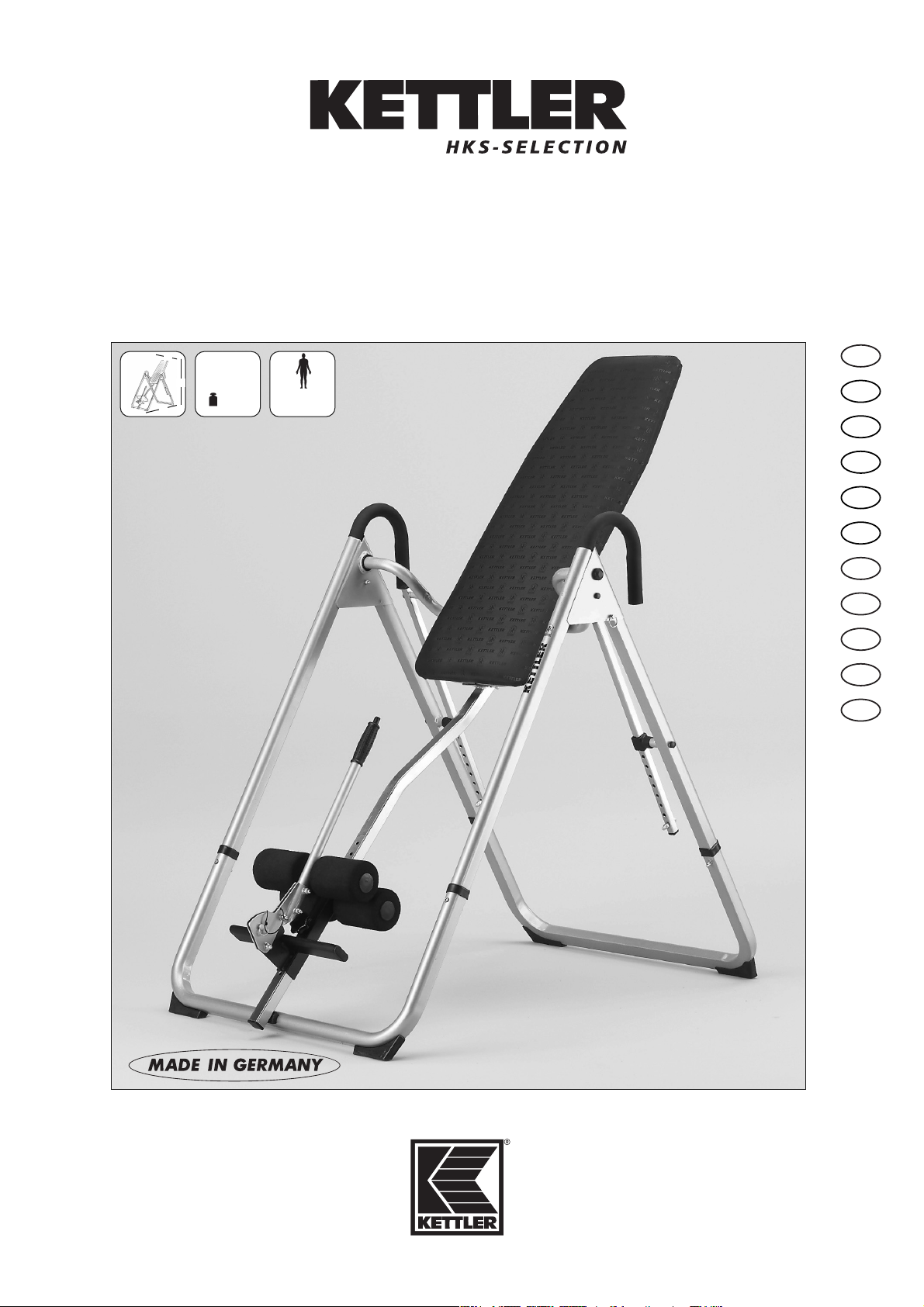
Montage- und Trainingsanleitung „APOLLO”
Art.-Nr. 07426-600
Auf 100% Altpapier!
Abb. ähnlich
I
E
NL
F
GB
A 150 cm
B85cm
C 226 cm
31 kg
max.
110 kg
C
A
B
D
PL
CZ
P
DK
RO
Page 2

4
Handling the equipment
■ Before using the equipment for exercise, check carefully to en-
sure that it has been correctly assembled.
■ It is not recommended to use or store the apparatus in a damp
room as this may cause it to rust. Please ensure that no part of
the machine comes in contact with liquids (drinks, perspiration
etc.). This may cause corrosion.
■ The machine is designed for use by adults and children should
not be allowed to play with it. Children at play behave unpredictably and dangerous situations may occur for which the manufacturer cannot be held liable. If, in spite of this, children are
allowed to use the equipment, ensure that they are instructed in
its proper use and supervised accordingly.
■ Use for your regular cleaning, maintenance and care our ap-
pliance maintenance set (Article no. 07921-000) specifically licensed for KETTLER Sports apparatus and available from the
Sport specialized trade.
■ Before beginning your first training session, familiarize yourself
thoroughly with all the functions and settings of the unit.
■ When choosing a place for the equipment please ensure that
the floor can withstand the additional weight/load.
■ Basically this equipment does not need any special maintenan-
ce.
GB Assembly Instructions
For Your Safety
ATTENTION! The training device should be used only for its
intended purpose, i.e. for physical exercise by adult people.
ATTENTION! Any other use of the equipment is prohibited and
may be dangerous. The manufacturer cannot be held liable for
damage or injury caused by improper use of the equipment.
■ The training device has been designed in accordance with the
latest standards of safety. Any features which may have been a
possible cause of injury have been avoided or made as safe as
possible.
■ The training device corresponds with DIN EN 957 -1/-9, class
HB. It is therefore unsuitable for therapeutic use.
■ Incorrect repairs and structural modifications (e.g. removal or
replacement of original parts) may endanger the safety of the
user.
■ Damaged components may endanger your safety or reduce the
lifetime of the equipment. For this reason, worn or damaged
parts should be replaced immediately and the equipment taken
out of use until this has been done. Use only original KETTLER
spare parts.
■ In case of enquiry, please contact your KETTLER dealer.
■ If the equipment is in regular use, check all its components tho-
roughly every 1–2 months. Pay particular attention to the tightness of bolts and nuts.
ATTENTION! Instruct people using the equipment (in particu-
lar children) on possible sources of danger during exercising.
■ Before beginning your program of exercise, consult your doctor
to ensure that you are fit enough to use the equipment. Base
your program of exercise on the advice given by your doctor.
Incorrect or excessive exercise may damage your health!
■ Any interference with parts of the product that are not descri-
!
!
!
Before assembling or using this fitness product, please read the following instructions carefully. They contain
important information for use and maintenance of the equipment as well as for your personal safety. Keep
these instructions in a safe place for maintenance purposes or for ordering spare parts.
bed within the manual may cause damage, or endanger the
person using this machine. Extensive repairs must only be carried out by KETTLER service staff or qualified personnel trained
by KETTLER.
■ To ensure that the safety level is kept to the highest possible stan-
dard, determined by its construction, this product should be serviced regulary (once a year) by specialist retailers.
■ Before use, always check all screws and plug-in connections as
well as respective safety devices fit correctly.
ATTENTION! While assembly of the product keep off chil-
dren’s reach (Choking hazard - contains small parts).
■ Always wear suitable shoes when using.
ATTENTION! Before beginning your program of training, stu-
dy the instructions for training carefully.
■ Our products are subject to a constant innovative quality assu-
rance. We reserve the right to perform technical modifications.
■ In choosing the location of the apparatus, ensure a sufficient
safety distance from any obstacles. The apparatus must not be
mounted in the immediate vicinity of main passageways (paths,
doorways, corridors).
■ The product is not suitable for use by persons weighing over
110 kg.
■ Nobody may be in the moving range of a training person du-
ring training
■ This exercise machine may only be used for exercises indicated
in the training instructions.
■ The surface on which the unit is placed must be firm and even.
Place rubber or straw mats under it to deaden any noise or impacts. Only for appliances with weights. Avoid powerful oscillations of the dumbbells!
!
!
Page 3

5
List of spare parts page 42-44
When ordering spare parts, always state the full article number,
spare-partnumber, the quantity required and the S/N of the product (see handling).
Example order: Art. no. 07426-600 / spare-part no. 70132713
/ 2 pieces / S/N ....................
Please keep original packaging of this article, so that it may be
used for transport at a later date, if necessary.
Goods may only be returned after prior arrangement and in (internal) packaging, which is safe for transportation, in the original
box if possible.
It is important to provide a detailed defect description / damage
report!
Important: spare part prices do not include fastening material; if
fastening material (bolts, nuts, washers etc.) is required, this
should be clearly stated on the order by adding the words „with
fastening material“.
Waste Disposal
KETTLER products are recyclable. At the end of its useful life please dispose of this article correctly and safely (local refuse sites).
KETTLER (GB) Ltd.
Merse Road · North Moons Moat · Redditch, Worcestershire B98 9HL · Great Britain
http://www.kettler.co.uk
KETTLER International Inc.
1355 London Bridge Road · VA 23450 Virginia Beach
USA
http://www.kettlerusa.com
USA
GB
GB Assembly Instructions
Instructions for Assembly
■ Ensure that you have received all the parts required (see check
list) and that they are undamaged. Should you have any cause
for complaint, please contact your KETTLER dealer.
■ Before assembling the equipment, study the drawings carefully
and carry out the operations in the order shown by the diagrams. The correct sequence is given in capital letters.
■ Please note that there is always a danger of injury when wor-
king with tools or doing manual work. Therefore please be careful when assembling this machine.
■ Ensure that your working area is free of possible sources of dan-
ger, for example don’t leave any tools lying around. Always dispose packaging material in such a way that it may not cause
any danger. There is always a risk of suffocation if children
play with plastic bags!
■ The equipment must be assembled with due care by an adult
person. If in doubt call upon the help of a second person, if possible technically talented.
■ The fastening material required for each assembly step is shown
in the diagram inset. Use the fastening material exactly as instructed. The required tools are supplied with the equipment.
■ Bolt all the parts together loosely at first, and check that they
have been assembled correctly. Tighten the locknuts by hand until resistance is felt, then use spanner to finally tighten nuts com-
pletely against resistance (locking device). Then check that all
screw connections have been tightened firmly. Attention: once
locknuts have been unscrewed they no longer function correctly
(the locking device is destroyed), and must be replaced.
■ For technical reasons, we reserve the right to carry out prelimi-
nary assembly work (e.g. addition of tubing plugs).
■ For machines with rope systems: please ensure that all ropes
are fixed correctly. This is especially important for latissimus
bars.
Page 4
24
0 10 20 30 40 50 60 70 80 90 100 110 120 130 140 150 160 170
M5x40
M8x40
M8
ø22
ø16
ø12
M6
M5
ø3,9x13
M5x40
Beispiel Examples Examples Bij voorbeeld
Ejemplas Esemp Przykłod Exemplo
Příklad Eksempel Exemplu
Messhilfe für Verschraubungsmaterial
– GB – Measuring help for screw connections
– F – Gabarit pour système de serrae
– NL – Meethulp voor schroefmateraal
– E – Ayuda para la medición del material de atornilladura
– I – Misura per materiale di avvitamento
– PL – Wzornik do połączeń śrubowych
– CZ – Měřící pomůcka pro materiál k přišroubování
– P – Auxiliar de medição para materiais de aparafusamento
– DK – Hjælp til måling af skruer
– RO – Ajutor pentru măsurarea materialului de înşurubat
– D – Gehört nicht zum Lieferumfang.
– GB – Not included.
– F – Ne fait pas partie du domaine de livraison.
– NL – Is niet bij de levering inbegrepen.
– E – No forma parte del volumen de entrega.
– I – Non in dotazione alla fornitura.
– PL – Nie należy do zakresu dostawy.
– CZ – Nepatří do rozsahu dodávky
– P – Não está incluído nas peças fornecidas
– DK – Er ikke inkluderet i leveringsomfanget.
– RO – Nu face parte din setul de livrare.
Page 5
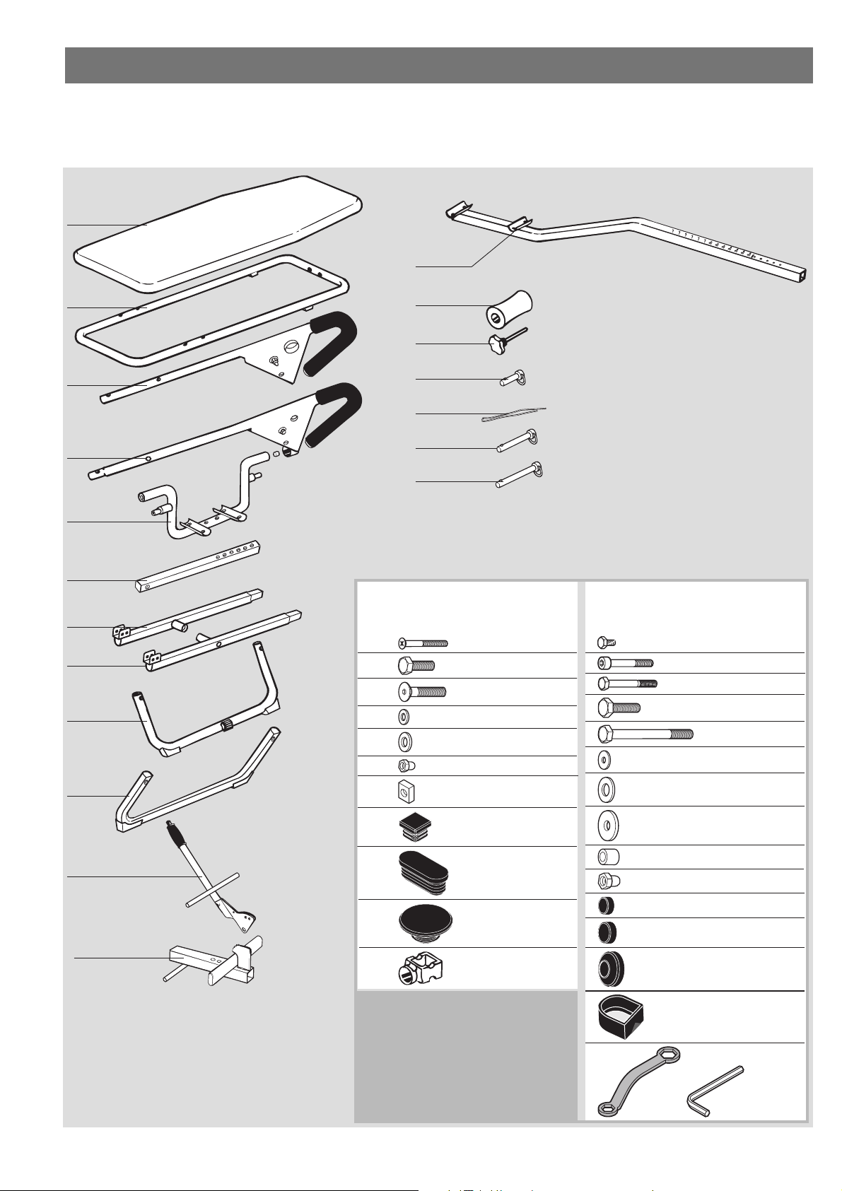
25
Die Maschinenbeutel Pos. 36 +
38 immer zusammen bestellen.
Checkliste (Packungsinhalt)
– GB – Checklist (contents of packaging)
– F – Liste de vérification (contenu de l’emballage)
– NL – Checklijst (verpakkingsinhoud)
– E – Lista de control (contenido del paquete)
– I – Lista di controllo (contenuto del pacco)
– PL – Lista kontrolna (zawartość opakowania)
– CZ – Kontrolní seznam (obsah balení)
– P – Lista de verificação (conteúdo da embalagem)
– DK – Checkliste (pakkens indhold)
– RO – Lista de verificare (conţinutul pachetului)
1x
1x
1x
1x
1x
1x
2x
1x
1x
1x
1x
4x
1x
1x
8x15
1x
2x
8x32
1x
8x41
Pos.-Nr. 36
Maschinenbeutel 1/2 91380158
M6
M8
4
1
8
6
13
6
2
M5x45
M8x25
M8x45
ø 12,5x6,4
ø 16x8,3
Pos.-Nr. 38
Maschinenbeutel 2/2 91380159
AM5x10
M6x45
M6x50
M8x30
M8x85
ø15,5x5,3
ø21x10,5
2
4
2
4
2
2
4
1x
1x
ø 25
2648
4
2
4
2
20x20
50x20
ø25x8,4
ø13x12
SW10
SW13
M8
2096
3364
2
2
11
2
2
2
4
21
Page 6

26
– D – Achten Sie beim Einsetzen der Fußbügel auf die dargestellte
richtige Lage der Fuß- bzw. Anschlagstopfen.
– GB – When inserting the foot bar, ensure that the foot and buffer
stops are in the correct position as shown.
– F – A la mise en place des cintres pour les pieds, veiller au position-
nement correct, comme représenté, par les bouchons de butée.
– NL – Let bij het aanbrengen van de voetbeugel op de afgebeelde -
correcte - positie van de voet- resp. aanslagdop.
– E – Al aplicar los estribos de pie observe la posición correcta de los
tapones de las patas o de tope.
– I – Quando si inserisce la staffa del piede fare attenzione che la po-
sizione dei tappi del piede e/o d´arresto sia corretta, come quella raffigurata.
– PL – Przy zakładaniu drążków pod stopy zwracać uwagę na przed-
stawione tu prawidłowe położenie zatyczek nożnych i ogranicznikowych.
– CZ – Při nasazování klipsen dbejte na vyobrazenou správnou pozici
nožních dorazů a dorazových nárazníků.
– P – Na colocação dos aros para os pés deve observar a posição
correcta representada dos tampões para os pés ou de batente.
– DK – Sørg for at fod- og stoppproppen sidder i den rigtige viste posi-
tion ved isætning af fodstøtten.
– RO – La montarea suportului pentru picior aveţi în vedere poziţia co-
rectă a dopurilor opritoare.
1
B
A
C
– D – Die Schraubverbindung noch nicht fest anziehen.
– GB –Do not tighten the bolts yet.
– F – Ne pas encore serrer la visserie à fond.
– NL – Draai de schroefverbinding nog niet vast aan.
– E – No apriete aún fuertemente los tornillos.
– I – Non serrare ancora i collegamenti a vite
– PL – Nie dokręcać jeszcze połączeń śrubowych.
– CZ – Šroubové spojení zatím nedotahujte napevno.
– P – Ainda não aperte a união roscada
– DK – Spænd ikke boltene endnu.
– RO – Încă nu strângeţi îmbinarea cu şuruburi.
C
1x
ø8x41
B
4x
M6x45 ø12,5x6,4 M6
A
2x
M6x50SW10 ø12,5x6,4 M6
!
Page 7

27
3
A
B
B
C
C
2
R
A
B
2x
M8x30 ø25x8,4
ø13x12
A
2x
AM5x10 ø21x10,5ø15,5x5,3
A
B
R
!
C
2x
M8x30 ø16x8,3 M8
A
2x
SW13 M8x85 ø16x8,3 M8
Page 8

28
4
5
1
8x
M8x45 ø16x8,3 M8
2x
ø8x32
Page 9

29
6
8 9
C
B
A
7
– D – Beim Eindrehen der Schrauben keinen Druck ausüben, da die Gefahr besteht, dass sich die innenliegenden
Muttern lockern.
– GB – When screwing the bolts in, do not use force as this may dislodge the nuts on the inside.
– F – Ne pas exercer de pression quand on visse, car on risque de desserrer les écrous intérieurs.
– NL – Oefen bij het aanbrengen van de schroeven geen druk uit, daar er gevaar bestaat, dat de binnenste moe-
ren losraken.
– E – No ejerza presión al atornillar los tornillos ya que existe el peligro de que se suelten las tuercas que se
encuentran en el interior.
– I – Quando si avvitano le viti non fare pressione, altrimenti c´è pericolo che i dadi all´interno si allentino.
– PL – Wkręcać śruby nie wywierając nacisku, ponieważ zachodzi wówczas obawa, że poluzują się położone
wewnątrz nakrętki.
– CZ – Při dotahování šroubů nevyvíjejte žádný tlak, protože vzniká nebezpečí, že by se uvolnily matky, které se
nacházejí uvnitř.
– P – Ao enroscar os parafusos não deve exercer qualquer pressão, uma vez que existe o perigo de desapertar
as porcas no interior.
– DK – Brug ikke unødig kraft, når boltene skrues på, da det kan løsne møtrikkerne på indersiden.
– RO – Nu exercitaţi presiune la înfiletarea şuruburilor, deoarece există pericolul slăbirii piuliţelor din interior.
4x
M5x45
C
1x
M8x25 ø16x8,3 M8
1x
ø8x15
Page 10

30
Instructions pour l’entraînement
F
Les douleurs dans le dos occasionnées par tensions, charges exagérées et les lésions dues aux surcharges de la colonne vertébrale comptent parmi les maladies les plus répandues de notre civilisation et les maladies professionnelles les plus fréquentes de
nos jours. Il est donc urgent de réagir de bonne heure à ces symptômes avant que ne se produisent par exemple des dommages
tels que la discopathie. Pour prévenir cette maladie populaire, les
exercices de relaxation et de détente sont indispensables pour la
colonne vertébrale et l’appareil moteur tout entier.
Avec l’appareil Apollo on déleste la colonne vertébrale. Les exercices permettent d’éviter la pression des disques intervertébraux
qui peuvent alors réabsorber le liquide et les substances nutritives
perdus en charge. De plus, les mouvements d’extension servent à
éliminer les tensions musculaires.
Rückenschmerzen durch Verspannungen, Fehlbelastungen und
Überlastungsschäden der Wirbelsäule gehören zu den weitverbreitetsten Zivilisations- und den am häufigsten angezeigten Berufskrankheiten unserer Zeit.
Daher ist es dringend erforderlich, frühzeitig diesen Beschwerden
entgegenzuwirken, bevor sich z. B. Bandscheibenschäden einstellen. Entspannungs- und Entlastungsübungen für die Wirbelsäule und den gesamten Bewegungsapparat beugen dieser Volkskrankheit vor.
Mit dem KETTLER APOLLO erreichen Sie eine Entlastung der Wirbelsäule. Hierbei wird der Druck von den Bandscheiben genommen, die die unter Belastung abgegebene Flüssigkeit sowie Nährstoffe wieder aufnehmen können. Des weiteren werden durch die
Streckung Muskelverspannungen gelöst.
Die „Über-Kopf-Lage” sorgt darüber hinaus für eine bessere
Durchblutung und Sauerstoff-Versorgung der Muskulatur sowie
wichtiger Organe der oberen Körperhälfte, insbesondere des Gehirns.
Orthopäden und Sportärzte empfehlen die „Über-Kopf-Lage” zur
Entlastung der Bandscheiben, der Hüft- und Kniegelenke sowie
zur Vorbeugung gegen Rückenschmerzen und Muskelverspannungen. Belastungsbedingte Rücken- und Gelenkschmerzen lassen spürbar nach beim Einsatz des APOLLO.
Backaches, stiffness, the effects of poor posture and overstrain
are among the most widespread complaints in our modern industrial civilization.
It is therefore essential to take early action to prevent such complaints from occurring, i.e. before the intervertebral disks are damaged beyond repair. Special exercises to relax spine and muscles are an effective way of doing this.
The KETTLER APOLLO reduces stress on the back and relieves
pressure on the intervertebral disks by allowing them to reabsorb
the fluids discharged when they are in action. The stretching process also helps to relieve tension in the muscles.
The "head downwards" position also ensures better circulation
and a more ample supply of oxygen to the muscles and important
organs in the upper part of the body, in particular the brain.
Orthopedists and physiotherapists recommend the "head
downwards" position for relieving stress on the vertebral disks,
the hips and knee joints, as well as for preventing muscular tension. Regular use of the APOLLO provides real relief from backaches and painful joints.
Exercising instructions
GB
Important note
Even if the unit is designed for use by one person, assistance from
a second person may be useful. Before you use the APOLLO,
have a check-up by your doctor to ensure you are fit enough to
do the exercises. Keep his advice in mind when working out your
training program. Remember that the wrong type of exercise or
excessive exercise may damage your health.
The device is not to be used if you have extremely high blood
pressure, glaucoma, acute organic or mental disturbances and
when pregnant.
Note on exercising
Begin your regular training in the "head downwards" position for
only one minute per day, and increase this by about half a minute daily over a period of time. Do not swing into the maximum position immediately, but work your way into it slowly as described
below. Relaxation and exercise with the APOLLO is especially recommended after long periods of strain on the back, e.g. after
driving long distances or in sedentary occupations etc.
Wichtige Hinweise
Auch wenn das Gerät für die Selbstbedienung konstruiert ist, sollte eine zweite Person sicherheitshalber Hilfestellung leisten.
Lassen Sie vor Übungsaufnahme durch Ihren Hausarzt abklären,
ob Sie für Übungen mit dem APOLLO gesundheitlich geeignet
sind. Der ärztliche Befund sollte Grundlage für den Aufbau Ihres
Trainingsprogramms sein. Falsches oder übermäßiges Training
kann zu Gesundheitsschäden führen.
Bei extremem Bluthochdruck, Augenhochdruck, akuten organischen oder psychischen Störungen und während der Schwangerschaft ist das Gerät nicht zu benutzen.
Trainingshinweise
Beginnen Sie Ihr regelmäßiges Training in „Über-Kopf-Lage” mit
einer Übungszeit von ca. 1 Minute und steigern Sie diese individuell um ca. 1/2 Minute täglich. Begeben Sie sich nicht sofort in
die maximale Übungsposition sondern „tasten” Sie sich allmählich - wie im folgenden Abschnitt beschrieben - an die vollständige „Über-Kopf-Lage” heran. Insbesondere nach vorangegangenen intensiven Belastungen der Wirbelsäule (längere Autofahrten,
sitzende Tätigkeit usw.) empfiehlt sich das Entspannungstraining
mit dem APOLLO.
La “position tête en bas” améliore l’irrigation sanguine et l’approvisionnement en oxygène de la musculature ainsi que d’importants organes de la partie supérieure du corps, en particulier
du cerveau.
Les orthopèdes et la médecine sportive recommandent la “position tête en bas” pour délester les disques intervertébraux, les articulations des hanches et des genoux, ainsi que pour prévenir les
douleurs dorsales et les tensions des muscles. Après l’utilisation
de l’appareil APOLLO, les douleurs du dos et des muscles, dues
aux sollicitations, diminuent sensiblement.
Consignes importantes
Bien que l’appareil ait été construit pour s’en servir soi-même, une
deuxième personne devrait être prévue, par mesure de sécurité,
pour venir éventuellement en aide.
Trainingsanleitung
D
Page 11

35
B
C
E
G
H
I
F
4
I
II
III
3
1 2
F
A
Einstellung in ganze Stufen
D
Einstellung in halben Stufen
D
D
– GB – Adjustment in whole increments
– F – Réglage en étapes complètes.
– NL – Instelling in hele treden.
– E – Ajuste de pasos enteros
– I – Regolazione per gradini interi
– PL – Nastawienie na całe stopnie
– CZ – Nastavení v celých stupních
– P – Ajuste em níveis inteiros
– DK – Indstilling i hel stigning
– RO – Reglarea în trepte complete
– GB – Adjustment in half increments.
– F – Réglage en demie étapes.
– NL – Instelling in halve treden.
– E – Ajuste de pasos medios.
– I – Regolazione per mezzi gradini
– PL – Nastawienie na połowy stopni
– CZ Nastavení v půlkách stupňů
– P – Ajuste em meios níveis
– DK – Indstilling i halv stigning
– RO – Reglarea în jumătate de trepte
Page 12

36
Am linken und rechten Standrohr des Gerätes befindet sich je
eine Rasterverstellung (Bild 5), die den maximalen Neigungswinkel des Pendels begrenzt. Stellen Sie vor dem Training mit dem
APOLLO den gewünschten maximalen Neigungswinkel ein. Es
stehen sechs Positionen (Rasterlöcher) zur Verfügung: Position 1
begrenzt das Pendel in der waagerechten Position (Stellung II,
Bild 4), die Positionen 2–5 in einem proportional größeren Neigungswinkel und die Position 6 in der steilsten „Über-Kopf-Lage“
(Stellung III, Bild 4). Anfänger sollten in jedem Fall mit einer geringen Neigung beginnen und sich allmählich an steilere Positionen herantasten.
Außerdem wird durch diese Sicherheitseinrichtung ein unbeabsichtigtes Herumschlagen des Pendels verhindert. Unbedingt an
beiden Rastersicherungen immer die gleiche Lochposition einstellen!
Zur optimalen Nutzung des Gerätes ist eine exakte Einstellung der
gesamten Fußeinheit notwendig. Nehmen Sie das Einstellen daher sehr sorgfältig und immer im Beisein einer zweiten Person zur
Hilfestellung vor, verfahren Sie wie folgt: Zunächst den Stellkörper
(B) in einer der unteren Lochungen des Fußrohres (C) durch Einsetzen des Steckgriffes (D) festsetzen. Die Klammern (F) nach Be-
tätigung des Druckknopfes (E) durch Vorschieben des Griffrohres
(A) öffnen. Den Rücken gegen die Polsterfläche lehnen und mit
den Füßen auf die Fußleisten (G) treten. Durch Druck auf das Griffrohr (A) in Richtung Körper die Klammern (F) schließen. Achtung!
Steckbolzensicherung nicht vergessen.
Den Körper mit angelegten Armen zurücklehnen (Stellung I,
Bild3). Verlagern Sie jetzt Ihren Körperschwerpunkt, indem Sie zunächst einen Arm langsam bis über den Kopf bewegen. Falls sich
das Pendel nicht aus seiner Ruhelage (Stellung I) bewegt, nehmen
Einstellen und Auspendeln des APOLLO
At the left and right side of the device’s frame there is an adjustment system (fig. 5) limiting the max. angle of inclination of the
pendulum. Before taking up training with the APOLLO, adjust the
desired angle of inclination. There are six positions (holes): Position 1 limits the pendulum in the horizontal position (position II,
fig. 4), positions 2-5 in a proportionally higher angle of inclination, and position 6 in the steepest "head-down position" (position
III, fig. 4). Beginners should start with a slight inclination and
slowly work towards steeper positions.
This safety device also makes an overturning of the pendulum impossible. Always use identical hole positions at both sides!
IFor the optimum use of the device, an exact setting of the entire
foot unit is necessary. Therefore be very careful when making a
setting and a second person should always be present to help,
proceed as follows: First lock the setting (B) in one of the bottom
holes of the foot pipe (C) through entering the drive handle (D).
Open the clamps (F) after activation of the push button (E) through
pushing through the grip pipe (A). Lean the back against the
upholstered surface and push with the feet on the foot bars (G).
Through pressure on the grip pipe (A) in the direction of the body
close the clamps (F). Attention! Do not forget the locking pin clips.
Lean back with the arms at your side (position I, fig. 3). Move the
centre of gravity of the body by raising one arm slowly over the
head. Should the swing not move from its resting position (position I) raise the second arm above the head, too. If the swing still
does not move, insert the adjusting device (B) into the next hole
upwards. Always ensure that the adjusting device is firmly locked
in position before beginning to exercise. Determine your ideal
point of balance by trial and error and mark or note the holes in
question. If you have determined your ideal point, you can con-
Adjustment and balancing of the APOLLO
Sie den zweiten Arm zu Hilfe. Reicht auch dieses noch nicht aus,
ist es notwendig, den Stellkörper (B) im nächst höheren Loch einzusetzen. Kontrollieren Sie stets vor Beginn Ihrer Übungen den festen Sitz des Stellkörpers. Tasten Sie sich auf diese Weise langsam an Ihren Idealpunkt heran und markieren oder merken Sie
sich diesen Punkt (Rasterloch). Haben Sie Ihren Idealpunkt ermittelt, können Sie jetzt mit einem oder beiden Armen sowohl die
Drehgeschwindigkeit steuern als auch das Pendel in jeder Position (Bild 4) bis zur eingestellten Neigungswinkel - Begrenzung anhalten. Durch leichten Zug an den Handgriffen können Sie sich
aus der „Über-Kopf-Lage” wieder in die Ausgangsstellung begeben.
Zur Einstellung des Stellkörpers bzw. für Ihre Übungen sollten Sie
sich dennoch (auch aus Sicherheitsgründen) der Hilfe einer weiteren Person bedienen.
Warnhinweise
Entfernen Sie Hindernisse aus dem Schwenkbereich des Fußrohres und weisen Sie beistehende Personen auf mögliche Gefährdungen während der Übungen hin. Nach Schließen der Klammer
(F, Bild 2) unbedingt den Sicherheitssteckbolzen (H) in eines der
Löcher (I) einsetzen. Trainieren Sie niemals ohne die Steckbolzensicherung!
trol the turning speed with one or with two arms and you can stop
the pendulum at any position (fig. 4) up to the adjusted angle of
inclination. By pulling slightly on the hand grips, you can move
from the "head downwards" position back into the starting position. When setting the balance of the swing, and during your
exercises, the assistance of a second person is recommended for
safety reasons.
Warnings
Remove obstacles from the foot tube's tilting range and inform assisting persons of possible risks during the exercises. Aways in-
sert the lockingy pin (H) into one of the holes (I) after closing the
bracket (F, fig. 2). Never exercise without the locking pin in position!
GB
D
Page 13

42
rio nonchè il numero di serie dell’apparecchio.
– PL – Przy zamawianiu części zamiennych proszę podawać komplet-
ny numer artykułu, numer części zamiennej i numer serii
urządzenia.
– CZ – Při objednání náhradních dílů prosím udejte úplné číslo zboží,
číslo náhradního dílu, potřebný počet kusů a sériové číslo
přístroje.
–P – Ao encomendar peças sobressalentes, por favor indique o nú-
mero completo do artigo, o número da peça sobressalente, o
número de unidades necessárias e o número de série do aparelho.
– DK – Ved bestilling af reservedele skal du altid opgive det fuldstændi-
ge artikelnummer, nummeret på reservedelen, det ønskede antal
og maskinens serienummer (se Håndtering).
– RO – La comandarea pieselor de schimb indicaţi numărul complet al
articolului, numărul piesei de schimb, numărul de bucăţi necesare şi seria aparatului.
–D – Geben Sie bei Ersatzteilbestellungen bitte die vollständige Arti-
kelnummer, die Ersatzteilnummer, die benötigte Stückzahl und
die Seriennummer des Gerätes an.
– GB – When ordering spare parts, always state the full article number,
spare-part number, the quantity required and theS/N of the product.
–F – En cas de commande de pièces de rechange, nous vous prions
de mentionner la référence article, le numéro de pièce de rechange, la quantité demandée et le numéro de série de l’appareil.
–NL –Vermeld bij de onderdelenbestellingen a.u.b. het volledige arti-
kelnummer, het onderdeelnummer, het benodigde aantal en het
serienummer van het apparaat.
–E – Indicar con los pedidos de piezas de repuesto el número com-
pleto del artículo, el número de la pieza de repuesto, las unidades solicitadas y el número de serie del aparato.
–I – Per l’ordinazione di parti di ricambio indicate il completo nume-
ro di articolo, della parte di ricambio, il numero di unit necessa-
Ersatzteilbestellung
– GB – Spare parts order
– F – Commande de pièces de rechange
– NL – Bestelling van reserveonderdelen
– E – Pedido de recambios
– I – Ordine di pezzi di ricambio
– PL – Zamówiene części zamiennych
– CZ – Objednání náhradních dílů
– P – Encomenda de peças sobressalentes
– DK – Bestilling af reservedele
– RO – Comandarea pieselor de schimb
–D – Beispiel Typenschild - Seriennummer
– GB – Example Type label - Serial number
–F – Example Plaque signalétique - Numèro
de serie
–NL –Bij voorbeeld Typeplaatje - Seriennum-
mer
–E – Ejemplo Placa identificativa - Número de
serie
–I – Esempio Targhetta tecnica - Numero di
serie
– PL – Przyklady Tabliczka identyfikacyjna - Nu-
mer serii
– CZ – Přiklad typového štítku – sériové číslo
–P – Exemplo placa de características - núme-
ro de série
– DK – Eksempel type label – serienummer
– RO – Exemplu plăcuţa de fabricaţie - seria
Page 14

43
Ersatzteilbestellung
APOLLO 07426-600
Pos.- Schwerkrafttrainer
Nr. Bezeichnung Stück Bestell-Nr.
1 Rückenpolster 1 94360225
2 Bodenrohr (hinten) mit Bodenschonern 1 94313336
3 Bodenrohr (vorne) mit Bodenschonern und Anschlagstück 1 94313338
4 Bodenschoner re. (3365) 2 70132712
5 Bodenschoner li. (3366) 2 70132713
6 Anschlagstück (536) 1 70110027
7 Einsteckrohr hinten (rechts) 1 94313340
8 Einsteckrohr hinten (links) 1 94313343
9 Griffrohr, rechts (kpl. mit Lagerbuchse, Stopfen für ø 30mm und Griffschlauch) 1 94313453
10 Lagerbuchse 1 10122000
11 Stopfen für ø30mm 1 10100033
12 Griffschlauch l=380mm 1 10118051
13 Griffrohr, links (kpl. mit Lagerbuchse, Stopfen für ø30mm und Griffschlauch) 1 94313964
14 Excenterbügel 1 94313458
15 Anschlagrohr mit Stopfen für VKT 20mm 2 97100592
16 Auflagerahmen 1 94313464
17 Fußrohr (m. Markieung) mit Stopfen für VKT 30mm 1 97100429
18 Stopfen für VKT 30mm 2 10100023
19 Stellkörper (kpl. mit Tellerstopfen für ø25mm und Ovalstopfen) 1 94314119
20 Polster l=140mm 4 10118042
21 Griffrohr 1 94313466
22 KS-Griff für ø25mm 1 10118009
23 Druckknopf 1 10122038
24 Druckfeder 1 25512052
25 Spanndraht 1 25012190
26 Mitnehmerzahn BL 446a 1 97200316
1
16
24
10
38
14
9
12
15
32
37
36
7
39
2
11
40
8
31
23
22
21
13
34
20
33
36
17
25
27
26
18
29
28
35
19
36
3
5
6
4
Page 15

44
Ersatzteilbestellung
APOLLO 07426-600
Pos.- Schwerkrafttrainer
Nr. Bezeichnung Stück Bestell-Nr.
27 Distanzrohr ø11x1,2x6,2mm 1 97200479
28 Sicherungsblech (rechts) 1 94313468
29 Sicherungsblech (links) 1 94313469
30 Schraubenbeutel o. Abb. 1 91380103
31 Lockingpin (41mm Nutzlänge) 1 13100000
32 Lockingpin (30mm Nutzlänge) 2 13100008
33 Lockingpin 8x15mm 1 13100006
34 Seil 300mm 1 10123050
35 Steckgriff 1 91380002
36 Maschinenbeutel 1/2 siehe Checkliste 1 91380158
37 Drehstück (2648) 2 70132711
38 Maschinenbeutel 2/2 siehe Checkliste 1 91380159
39 Abdeckkrawatte (3364) 4 70132714
40 Abdeckkappe (2096) 2 70127541
HEINZ KETTLER GmbH & Co. KG · Postfach 1020 · D-59463 Ense-Parsit
www.kettler.de
docu 94v/08.09
 Loading...