

Page 1
Sauter GmbH
Ziegelei 1
E-Mail: info@sauter.eu
Internet: www.sauter.eu
Ultrasonic Thickness Gauge
SAUTER TN-EE
Version 1.0
02/2014
D-72336 Balingen
Instruction Manual
Multi Mode
GB
Tel: +49-[0]7433- 9933-199
Fax: +49-[0]7433-9933-149
TN_EE -BA-e-1410
Page 2

GB
SAUTER TN-EE
Instruction Manual Ultrasonic Thickness Ga uge
Version 1.0 02/2014
Thank you for buying a SAUTER Material Thickness Gauge. We hope you are
pleased with your high quality instrument and with its big functional range. If you
have any queries, wishes or helpful suggestions, do not hesitate to call our service
number.
Summary:
1 Overview ......................................................................................................... 3
1.1 Product Specifications............................................................................................................. 3
1.2 Main Functions ......................................................................................................................... 3
1.3 Measuring Principle ................................................................................................................. 4
1.4 Configuration ............................................................................................................................ 4
1.5 Operating Conditions ............................................................................................................... 4
2 Keypad & Screen ........................................................................................... 5
2.1 Keypad Definitions ................................................................................................................... 5
3 Preparation ..................................................................................................... 6
3.1 Transducer Selection ............................................................................................................... 6
3.2 Condition and Preparation of Sur faces .................................................................................. 7
4 Operation ........................................................................................................ 8
4.1 Power On/Off ............................................................................................................................. 8
4.2 Setting the Measurement Mode .............................................................................................. 8
4.3 Perform Probe Zero .................................................................................................................. 8
4.4 Sound Velocity Calibration ...................................................................................................... 9
4.4.1 Calibration to a known thickness ................................................................................................ 9
4.4.2 Calibration to a known velocity ................................................................................................. 10
4.4.3 Two Point Calibration ............................................................................................................... 10
4.5 Performing Measurements .................................................................................................... 11
4.6 Scan mode .............................................................................................................................. 11
4.7 Changing Resolution ............................................................................................................. 12
4.8 Changing Units ....................................................................................................................... 12
4.9 Memory Management ............................................................................................................. 12
4.9.1 Storing a reading ...................................................................................................................... 12
4.9.2 Clearing selected file ................................................................................................................ 12
4.9.3 Viewing/deleting stored record ................................................................................................. 12
4.10 EL Backlight ............................................................................................................................ 13
4.11 Battery Information ................................................................................................................ 13
4.12 Auto Power Off ....................................................................................................................... 13
4.13 System Reset .......................................................................................................................... 13
4.14 Connecting to a Computer .................................................................................................... 13
5 Servicing ....................................................................................................... 13
6 Transport and Storage ................................................................................ 14
7 Declaration of Conformity ........................................................................... 16
2 TN_EE-BA-e-1410
Page 3

1 Overview
The model TN-EE is a multi-mode ultrasonic thickness gauge. Based on the same
operating principles as SONAR, the instrument is capable of measuring the thickness
of various materials with accuracy as high as 0.1/0.01 millimeters.
The multi-mode feature of the gauge allows the user to toggle between pulse-echo
mode and echo-echo mode (eliminating paint or coating thickness).
1.1 Product Specifications
There are two models available with the following measurement ranges:
-. TN 30-0.01EE
-. TN 60-0.01EE
1) Display:4.5 digits LCD with EL backlight.
2) Measurement Range: Pulse-Echo mode: (0.65~600)mm (in S teel), valid for both
models
Echo-Echo mode: (3~60) mm for TN 60-0.01EE.
Echo-Echo mode: (3~30) mm for TN 30-0.01EE
3) Sound Velocity Range: (1000~9999) m/s.
4) Resolution: 0.1mm/ 0.01mm
Accuracy: ±(0.5%Thickness+0.01)mm, depending on materials and conditions
5) Memory for up to 20 files (up to 99 values for each file) of stored values.
6) Power Source: Two “AA” size, 1.5 Volt alkaline batteries. 100 hours typical operating time (EL backlight off).
7) Communication:USB1.1.
8) Dimensions:150mm × 74mm × 32 mm.
9) Weight:245g
1.2 Main Functions
1) Multi-mode: Pulse-Echo mode and Echo-Echo mode.
2) Capable of performing measurements on a wide range of materials, including
metals, plastic, ceramics, composites, epoxies, glass and other ultrasonic wave
well-conductive materials.
3) Transducer models are available for special applications, including for coarse
grain material and high temperature applications.
4) Sensor Zero function, Soun d-Velocity-Calibration function
5) Two-Point- calibration function
6) Single point mode and Scan mode. Seven measurements readings per second in
single point mode, and sixteen per second in Scan Mode.
7) Coupling status indicator showing the coupling status.
8) Units: Metric/Imperial unit selectable.
9) Battery information indicates the rest capacity of the battery.
10) Auto sleep and auto power off function to conserve battery life.
11) Optional software to process the memory data on the PC.
TN_EE-BA-e-1410 3
Page 4
1.3 Measuring Principle
2
tv
H
×
=
No
Item
Qty.
Note
Standard
1
Main body
1
2
Sensor P5EE,
10 MHz, Ø 10mm
1
3
Couplant
1 4
Transport Case
1 5
Instruction Manual
1
6
Alkaline battery
2
AA
size
Optional
ration
11
Data Software
1
The digital ultrasonic thickness gauge determines the thickness of a part or structure
by accurately measuring the time required for a short ultrasonic pulse generated by a
transducer to travel through the thickness of the material, reflect from the back or inside surface, and be returned to the transducer. The measured two-way transit time
is divided by two to account for the down-and-back travel path, and then multiplied by
the velocity of sound in the material. The result is expressed in the well-known
relationship:
Where: H-Thickness of the test piece.
v-Sound Velocity in the material.
t-The measured roun d-trip transit time.
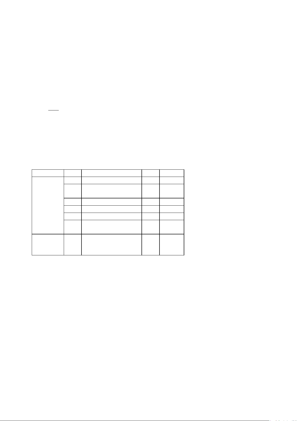
1.4 Configuration
Table 1-1
Configuration
Configu-
(ATU-04)
1.5 Operating Conditions
Operating Temperature: -20℃~+60℃;
Storage Temperature :-30℃~+70℃
Relative Humidity: ≤90%
In the environment of usage vibrations, strong magnetic field, corrosive medium and
heavy dust should be avoided.
4 TN_EE-BA-e-1410
Page 5
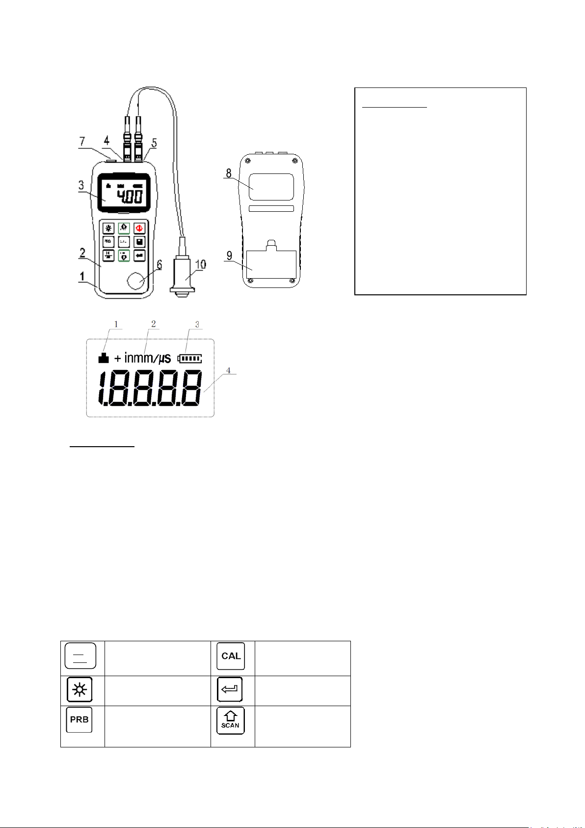
2 Keypad & Screen
ON
Turn the instru-
Sound velocity
Turn on/off the EL
Enter
Probe-Zero
Plus;
Turn on/off
Scan mode
1. 2.1 Main Screen
Explanation:
ULTRASONIC
THICKNESS GAUGE
SN:
POWER: 2 X 1.5V
Explanation:
1 The main body
2 Keypad
3 LCD display
4 Pulse socket
5 Receiver socket
6 Sensor zero disc
7 Communication port
8 Label
9 Battery cover
10 Measurement head
1. Coupling Status: Indicates the coupling status. While the gauge is taking a
measurement, the coupling status should be on. If it is not on or not stable, the
gauge is having difficulties in achieving a stable measurement, and the thickness value displayed will most likely be erroneous.
2. Unit: Current unit system. “mm” or “in” for thickness value. “m/s” or “in/μs” for
sound velocity.
3. B attery Information: Displays the rest capacity of the battery.
4. Information Display: Displays the measured thickness value, the sound
velocity and shows hints of current operation.
2.1 Keypad Definitions
ON
OFF
OFF
ment on/off
backlight
operation
calibration
TN_EE-BA-e-1410 5
Page 6

Unit switch be-
Minus;
Switch between
echo and
mode
Data Save or Da-
3 Preparation
3.1 Transducer Selection
The gauge is inherently capable of performing measurements on a wide range of materials, from various metals to glass and plastics. Different types of material, however,
will require the use of different transducers. Choosing the correct transducer for an
application is much important to perform easily accurate and reliable measurements.
The following paragraphs highlight the important properties of transducers, which
should be considered when selecting a transducer for a specific application.
Generally speaking, the best transducer for an application is one that sends sufficient
ultrasonic energy into the material being measured in the way that a strong, stable
echo is received by the gauge. Several factors affect the strength of ultrasound as it
travels. These are outlined bel ow:
Initial Signal Strength: The stronger a signal is to begin with, the stronger its return
echo will be. Initial signal strength is largely a factor of the size of the ultrasound
emitter in the transducer. A large emitting area will send more energy into the material being measured than a small emitting area. Thus, a so-called “1/2 inch” transducer
will emit a stronger signal than a “1/4 inch” transducer.
Absorption and Scattering: As ultrasound travels through any material, it is partly absorbed. If the material through which the sound travels has any grain structure, the
sound waves will experience scattering. Both of these effects reduce the strength of
the waves, and thus, the gauge’s ability to detect the returning echo. Higher frequency ultrasound is absorbed and scattered more than ultrasound of a lower frequency.
While it may seem that using a lower frequency transducer might be better in every
instance, low frequencies are less directional than high frequencies. Thus, a higher
frequency transducer would be a better choice for detecting the exact location of
small pits or flaws in the material being measured.
Geometry of the transducer: The physical constraints of the measuring environment
sometimes determine a transducer’s suitability for a given job. Some transducers
may simply be too large to be used in tightly confined areas. Also, the surface area
available for contacting with the transducer may be limited, requiring the use of a
transducer with a small bearing face. Measuring on a curved surface, such as an engine cylinder wall, may require the use of a transducer with a matching curved bearing face.
Temperature of the material: When it is necessary to measure on surfaces that are
exceedingly hot, high temperature transducers must be used. These transducers are
built using special materials and techniques that allow them to withstand high temperatures without damage. Additionally, care must be taken when performing a “Sensor-Zeroing” or “Calibration to Known Thickness” with a high temperature transducer.
Selection of the proper transducer is often a matter of tradeoffs between various
characteristics. It may be necessary to experiment with a variety of transducers in
order to find one that works well for a given application.
6 TN_EE-BA-e-1410
tween Metric and
Imperial system
ta Delete
pulseecho-echo
Page 7

The transducer is the “business end” of the instrument. It transmits and receives ul-
Model
Frequence
MHz
Φmm
Measurement
range
Lower limit
Annotation
P5EE
5
10
P-E: 2~600 mm
E-E:3~30/60 mm
Φ20 mm×3,0 mm
Standard
measurement
trasonic sound waves that the instrument uses to calculate the thickness of the material being measured. The transducer connects to the instrument via the attached cable, and two coaxial connectors. When using transducers, the orientation of the dual
coaxial connectors is not critical: either plug may be fitted to either socket in the instrument.
The transducer must be used correctly in order for the instrument to produce accurate, reliable measurements. Below is a short description of the transducer, followed
by instructions for its use.
Left figure is a bottom view of a typical transducer. The two semicircles of the bearing
face are visible, as is the barrier separating them. One of the semicircles is responsible for conducting ultrasonic sound into the material being measured, and the other
semicircle is responsible for conducting the echoed sound back into the transducer.
When the transducer is placed against the material being measured, it is the area
directly beneath the center of the bearing face that is being measured.
Right figure is a top view of a typical transducer. Press against the top with the thumb
or index finger to hold the transducer in place. Moderate pressure is sufficient, as it is
only necessary to keep the transducer stationary, and the bearing face seated flat
against the surface of the material being measured.
Tabelle Nr. 3-1 Suitable Measurement head
3.2 Condition and Preparation of Surfaces
In any ultrasonic measurement scenario, the shape and roughness of the test surface are of paramount importance. Rough, uneven surfaces may limit the penetration
of ultrasound through the material, and result in unstable, and therefore unreliable,
measurements. The surface being measured should be clean, and free of any small
particulate matter, rust, or scale. The presence of such obstructions will prevent the
transducer from seating properly against the surface. Often, a wire brush or scraper
will be helpful in cleaning surfaces. In more extreme cases, rotary sanders or grinding wheels may be used, though care must be taken to prevent surface gouging,
which will inhibit proper transducer coupling.
Extremely rough surfaces, such as the pebble-like finish of some cast iron , will prove
most difficult to measure. These kinds of surfaces act on the sound beam like frosted
glass on light, the beam becomes diffused and scattered in all directions.
In addition to posing obstacles to measurement, rough surfaces contribute to excessive wear of the transducer, particularly in situations where the transducer is
“scrubbed” along the surface. Transducers should be inspected on a regular basis,
for signs of uneven wear of the bearing face. If the bearing face is worn on one side
more than another, the sound beam penetrating the test material may no longer be
TN_EE-BA-e-1410 7
Page 8

perpendicular to the material surface. In this case, it will be difficult to exactly locate
tiny irregularities in the material being measured, as the focus of the sound beam no
longer lies directly beneath the transducer.
4 Operation
4.1 Power On/Off
The instrument is turned on by pressing the key. When the gauge is turned on, it
will first perform a brief display test by illuminating all of the segments in the display.
After one second, the gauge will display the sound velocity now used, indicating the
gauge is ready for use.
The gauge can be turned off by pressing the key. The tool has a special memory
that retains all of its settings even when the power is off. The gauge also features an
auto-power down mode designed to conserve battery life. If the gauge is idle for 5
minutes, it will turn itself off.
4.2 Setting the Measurement Mode
Often time users and inspectors in the field are faced with coated materials such as
pipes and tanks. Typically inspectors will need to remove the paint or coating prior to
measuring, or allow for some fixed amount of error introduced by the paint or coating
thickness and velocit y .
The error can be eliminated with this gauge by using a special echo-echo mode to
perform measurements for applications such as this. The gauge gives you this feature in a simple way, one button toggle, eliminating the need to remove the paint or
coating.
To switch between pulse-echo mode and echo-echo mode, simply press the key.
4.3 Perform Probe Zero
Note: The Probe Zero operation is onl y to be applied in Pulse-Echo mode, not
in Echo-Echo mode.
The key is used to “zero” the instrument in much the same way that a mechanical
micrometer is zeroed. If the gauge is not zeroed correctly, all the measurements that
the gauge makes may be in error by some fixed value. When the instrument is “zeroed”, this fixed error value is measured and automatically corrected for all subsequent measurements. The instrument may be “zeroed” by performing the following
procedure:
1) Plug the transducer into the instrument. Make sure that the connectors are fully
engaged. Check that the bearing face of the transducer is clean and free of any
debris.
2) Press the key to activate the zero mode.
8 TN_EE-BA-e-1410
Page 9

3) Use the key and the key to scroll to the probe model currently being used.
Be sure to set the right probe model to the instrument. Otherwise, there will be errors or deviations.
4) Apply a single droplet of ultrasonic couplant to the face of the metal probe disc.
5) Press the transducer against the probe disc, making sure that the transducer sits
flat against the surface.
6) Remove the transducer from the probe disc.
At this point, the instrument has successfully calculated its internal error factor, and
will compensate for this value in any subsequent measurements. When performing
an “instrument zero”, the instrument will always use the sound velocity value of the
built-in probe disc, even if some other velocity value has been entered for making
actual measurements. Though the instrument will remember the last “probe zero”
performed, it is generally a good idea to perform an “probe zero” whenever the gauge
is turned on, as well as any time a different transducer is used. This will ensure that
the instrument is always correctly zeroed.
Press while in probe zero mode will stop current probe zero operation
and return to the meas ur em ent mo de.
4.4 Sound Velocity Calibration
In order for the gauge to make accurate measurements, it must be set to the correct
sound velocity for the material being measured. Different types of material have different inherent sound velocities. If the gauge is not set to the correct sound velocity,
all of the measurements the gauge makes will be erroneous by some fixed percentage. The One-Point calibration is the simplest and most commonly used calibration
procedure optimizing linearity over large ranges. The Two-point calibration allows for
greater accuracy over small ranges by calculating the probe zero and velocity.
Note: One and Two point calibrations must be performed on material with the paint
or coating removed. Failure to remove the paint or coating prior to calibration will result in a multi material velocity calculation that may be different from the actual material velocity intended to be measured.
4.4.1 Calibration to a known thickness
Note: This procedure requires a sample piece of the specific material to be measured, the exact thickness of which is known, e.g. from having been measured by
some other means.
1) Perform a Probe-Zero.
2) Apply couplant to the sample piece.
3) Press the transducer against the sample piece, making sure that the transducer
sits flat against the surface of the sample. The display should show some thickness value, and the coupling status indicator should appear steadily.
4) Having achieved a stable reading, remove the transducer. If the displayed thickness changes from the value shown while the transducer was coupled, repeat
step 3.
5) Press the key to activate the calibration mode. The MM (or IN) symbol should
begin flashing.
6) Use the key and the key to adjust the displayed thickness up or down, until
it matches the thickness of the sample piece.
TN_EE-BA-e-1410 9
Page 10

7) Press the key again. The M/S (or IN/μS) symbols should begin flashing. The
gauge is now displaying the sound velocity value it has calculated based on the
thickness value that was entered.
8) Press the key once again to exit the calibration mode and return to the measurement mode. The gauge is now ready to perform measurements.
4.4.2 Calibration to a known velocity
Note: This procedure requires that the operator knows the sound velocity of the material to be measured. A table of common materials and their sound velocities can be
found in Appendix B of this manual.
1) Press the key to activate the calibration mode. The MM (or IN) symbol should
begin flashing.
2) Press the key again, so that The M/S (or IN/μS) symbols are flashing.
3) Use the key and the key to adjust the sound velocity value up or down, until
it matches the sound velocity of the material to be measured. You can also press
the key to switch among the preset commonly using velocities.
4) Press the key to exit from the calibration mode. The gauge is now ready to
perform measurements.
To achieve the most accurate measurements possible, it is generally advisable to
always calibrate the gauge to a sample piece of known thickness. Material composition (and thus, its sound velocity) sometimes varies from lot to lot and from manufacturer to manufacturer. Calibration to a sample of known thickness will ensure that the
gauge is set as closely as possible to the sound velocity of the material to be measured.
4.4.3 Two Point Calibration
Note: This procedure requires that the operator has two known thickness points on
the test piece that are representative of the range to be measured.
1) Probe-Zero has to be performed fir st.
2) Apply couplant to the sample piece.
3) Press the transducer against the sample piece, at the first/second calibration
point, making sure that the transducer sits flat against the surface of the sample.
The display should show some (probably incorrect) thickness value, and the coupling status indicator should appear steadily.
4) Having achieved a stable reading, remove the transducer. If the displayed thickness changes from the value shown while the transducer was coupled, repeat
step 3.
5) Press the key. The MM (or IN) symbol should begin flashing .
6) Use the key and the key to adjust the displayed thickness up or down, until
it matches the thickness of the sample piece.
7) Press the key. The display will flash 1OF2. Repeat steps 3 through 6 on the
second calibration point.
8) Press the key, so that The M/S (or IN/μS) symbols are flashing. The gauge will
now display the sound velocity value it has calculated based on the thickness values that were entered in step 6.
9) Press the key once more to exit the calibration mode. The gauge is now ready
to perform measurements within this range.
10 TN_EE-BA-e-1410
Page 11

4.5 Performing Measurements
When the instrument is displaying thickness measurements, the display will hold the
last value measured, until a new measurement is made.
In order for the transducer to do its job, there must be no air gaps between the wearface and the surface of the material being measured. This is accomplished with the
use of a “coupling” fluid, commonly called “couplant”. This fluid serves to “couple”, or
transfer, the ultrasonic sound waves from the transducer, into the material, and back
again. Before attempting to make a measurement, a small amount of couplant should
be applied to the surface of the material being measured. Typically, a single droplet
of couplant is sufficient.
After applying couplant, press the transducer (bearing face down) firmly against the
area to be measured. The coupling status indicator should appear, and a digit number should appear in the display. If the instrument has been properly “zeroed” and set
to the correct sound velocity, the number in the display will indicate the actual thickness of the material directly beneath the transducer.
If the coupling status indicator does not appear, not stable, or the numbers on the
display seem erratic, firstly check to make sure that there is an adequate film of
couplant beneath the transducer, and that the transducer is seated flat against the
material. If the condition persists, it may be necessary to select a different transducer
(size or frequency) for the material being measured.
While the transducer is in contact with the material that is being measured, the instrument will perform four measurements every second, updating its display as it
does so. When the transducer is removed from the surface, the display will hold the
last measurement mad e.
Note:Occasionally, a small film of couplant will be drawn out between the transducer and the surface as the transducer is removed. When this happens, the gauge may
perform a measurement through this couplant film, resulting in a measurement that is
larger or smaller than it should be. This phenomenon is obvious when one thickness
value is observed while the transducer is in place, and another value is observed after the transducer is removed. In addition, measurements through very thick paint or
coatings may result in the paint or coating being measured rather than the actual material intended. The responsibility for proper use of the instrument, and recognition of
these types of phenomenon, rests solely with the user of the instrument.
4.6 Scan mode
While the gauge excels at making single point measurements, it is sometimes desirable to examine a larger region, searching for the thinnest point. The gauge includes
a feature, called Scan Mode, which allows it to do just that.
In normal operation, the gauge performs and displays four measurements every second, which is quite adequate for single measurements. In Scan Mode, however, the
gauge performs ten measurements every second, and displays the readings while
scanning. While the transducer is in contact with the material being measured, the
gauge is keeping track of the lowest measurement it finds. The transducer may be
“scrubbed” across a surface, and any brief interruptions in the signal will be ignored.
When the transducer loses contact with the surface for more than two seconds, the
gauge will display the smallest measurement it found. When the transducer is removed from the material being scanned, the gauge will display the smallest measurement it found.
TN_EE-BA-e-1410 11
Page 12

When the scan mode is turned off, the single point mode will be automatically turned
on. Turn on/off the scan mode by the following steps:
Press the key to switch the scan mode on and off. It will display the current condition of the scan mode on the main screen.
4.7 Changing Resolution
The gauge has selectable display resolution, which is 0.1mm and 0.01mm.
Press down the key while turning on the gauge will switch the resolution between
“High” and “Low”.
4.8 Changing Units
On the measurement mode, press the key to switch back and forth between imperial and metric units.
4.9 Memory Management
4.9.1 Storing a reading
There are twenty files (F00-F19) that can be used to store the measurement values
inside the gauge. At most 100 records (thickness values) can be stored to each file.
By simply pressing the key after a new measurement reading appears, the measured thickness value will be saved to current file. It is added as the last record of the
file. To change the destination file to store the measured values, follow the steps:
1) Press the key to activate the data logging functions. It will display the current
file name and the total record count o f the file .
2) Use the key and the key to select the desired file to set as current file.
3) Press the key to exit the data logging functions at any time.
4.9.2 Clearing selected file
The user may require the contents of an entire file be completely cleared of all measurements. This would allow the user to start a new list of measurements starting at
storage location L00. The procedure is outlined in the following steps.
1. Press the key to activate the data logging functions. It will display the current
file name and the total record count o f the file .
2. Use the key and the key to scroll to the file that will be cleared of all meas-
urements.
3. Press the key on the desired file. It will automatically clear the file, and display
“-DEL”.
4. Press the key, at any time, to exit the data logging functions and return to
measurement mode.
4.9.3 Viewing/deleting stored record
This function provides the user with the ability to view/delete a record in a desired file
previously saved in memory. Following is the steps:
1. Press the key to activate the data logging functions. It will display the current
file name and the total record count o f the file .
2. Use the key and the key to select the desired file.
12 TN_EE-BA-e-1410
Page 13

3. Press the key to enter the selected file. It will display the current record num-
ber (for example, L012) and the record content.
4. Use the key and the key to select the desired record.
5. Press the key on the desired record. It will automatically delete this record,
and display “-DEL”.
6. Press the key to exit the data logging functions and return to measurement
mode.
4.10 EL Backlight
With the background light, it is convenient to work in the dark condition. Press key
to switch on or switch off the background light at any moment as you need after power on. Since the EL light will consume much power, turn on it only when necessary.
4.11 Battery Information
Two AA size alkaline batteries are needed as the power source. After several hours’
usage of the preset batteries, the battery symbol on the screen will be shown as
. The more of dark part indicates the more close to fill. When the battery capacity runs out, the battery symbol will be shown as and will begin to flash.
When this occurs, the batteries should be replaced.
Please take out the batteries when not working during a long period of time.
4.12 Auto Power Off
The instrument features an auto power off function designed to conserve battery life.
If the tool is idle for 5 minutes, it will turn itself off. While the voltage of the battery is
too low this function will also work.
4.13 System Reset
Press down the key while powering on the instrument will restore factory defaults.
All the memory data will be cleared during system reset. The only time this might
possibly helpful is if the parameter in the gauge was somehow corrupted.
4.14 Connecting to a Computer
The gauge is equipped with a USB port. Using the accessory cable, the gauge has
the ability to be connected to a computer, or external storage device. Measurement
data stored in the memory of the gauge can be transferred to the computer through
the USB port. Detailed information of the communication software and its usage refer
to the software manual.
5 Servicing
When the tester appears some other abnormal phenomena, please do not dismantle
or adjust any fixed assembled parts. Just contact us by e-mail or phone and the follow-up for a (warranty) service can be initiated.
TN_EE-BA-e-1410 13
Page 14

6 T ransport and Storage
Keep it away from vibration, strong magnetic field, corrosive medium and dust.
Storage in ordinary temperature.
Appendix A: Applications Notes
Measuring pipes and tubes
When measuring a piece of pipe to determine the thickness of the pipe wall, orientation of the transducers is important. If the diameter of the pipe is larger than approximately 4 inches, measurements should be made with the transducer oriented so that
the gap in the bearing face is perpendicular (at right angle) to the long axis of the
pipe. For smaller pipe diameters, two measurements should be performed, one with
the bearing face gap perpendicular, another with the gap parallel to the long axis of
the pipe. The smaller of the two displayed values should then be taken as the thickness at that point.
Measuring laminated mat er ial s
Laminated materials are unique in that their density (and therefore sound-velocity)
may vary considerably from one piece to another. Some laminated materials may
even exhibit noticeable changes in sound-velocity across a single surface. The only
way to reliably measure such materials is by performing a calibration procedure on a
sample piece of known thickness. Ideally, this sample material should be a part of the
same piece being measured, or at least from the same lamination batch. By calibrating to each test piece individually, the effects of variation of sound-velocity will be
minimized.
An additional important consideration when measuring laminates, is that any included
air gaps or pockets will cause an early reflection of the ultrasound beam. This effect
will be noticed as a sudden decrease in thickness in an otherwise regular surface.
While this may impede accurate measurement of total material thickness, it does
provide the user with positive indication of air gaps in the laminate.
Measuring through paint & coatings
Measuring through paints and coatings are also unique, in that the velocity of the
paint/ coating will be significantly different form the actual material being measured. A
perfect example of this would be a mild steel pipe with approximately 0.6mm of coating on the surface. Where the velocity of the pipe is 5920m/s, and the velocity of the
paint is 2300m/s. If the user is calibrated for mild steel pipe and measures through
both materials, the actual coating thickness will appear to be 2.5 times thicker than it
actually is, as a result of the differences in velocity. This error can be eliminated by
using a special echo-echo mode to perform measurements for applications such as
14 TN_EE-BA-e-1410
Page 15

these. In echo-echo mode, the paint/ coating thickness will be eliminated entirely and
the steel will be the only material measured.
Suitability of materials
Ultrasonic thickness measurements rely on passing a sound wave through the material being measured. Not all materials are good at transmitting sound. Ultrasonic
thickness measurement is practical in a wide variety of materials including metals,
plastics, and glass. Materials that are difficult include some cast materials, concrete,
wood, fiberglass, and some rubber.
Couplants
All ultrasonic applications require some medium to couple the sound from the transducer to the test piece. Typically a high viscosity liquid is used as the medium. The
sound used in ultrasonic thickness measurement does not travel through air efficiently.
A wide variety of couplant materials may be used in ultrasonic gauging. Propylene
glycol is suitable for most applications. In difficult applications where maximum transfer of sound energy is required, glycerin is recommended. However, on some metals
glycerin can promote corrosion by means of water absorption and thus may be undesirable. Other suitable couplants for measurements at normal temperatures may include water, various oils and greases, gels, and silicone fluids. Measurements at elevated temperatures will require specially formulated high temperature couplants.
Inherent in ultrasonic thickness measurement is the possibility that the instrument will
use the second rather than the first echo from the back surface of the material being
measured while in standard pulse-echo mode. This may result in a thickness reading
that is TWICE what it should be. The Responsibility for proper use of the instrument
and recognition of these types of phenomenon rests solely with the user of the instrument.
TN_EE-BA-e-1410 15
Page 16

7 Declaration of Conformity
Sauter GmbH
Ziegelei 1
Ziegelei 1
Manifestamos en la presente que el producto al que se refiere esta
Signature
Datum
07.04.2009
Ort der Ausstellung
72336 Balingen
Albert Sauter
SAUTER GmbH
Geschäftsführer
Managing director
SAUTER GmbH, Ziegelei 1, D-72336 Balingen, Tel. +49-[0]7433/9933-199
Fax +49-[0]7433/9933-149, E-Mail: info@sauter.eu, Inter net: www .sauter.eu
D-72336 Balingen
E-Mail: info@sauter.eu
D-72336 Balingen
E-Mail: info@sauter.eu
Konformitätserklärung
Declaration of conformity for apparatus with CE mark
Konformitätserklärung für Geräte mit CE-Zeichen
Déclaration de conformité pour appareils portant la marque CE
Declaración de conformidad para aparatos con marca CE
Dichiarazione di conformità per apparecchi contrassegnati con la marcatura CE
D
GB
E
F
I
Konformitätserklärung
Declaration of
conformity
Declaración de
conformidad
Déclaration de
conformité
Dichiarazione di
conformità
Wir erklären hierm it, dass das Produkt, auf das sich diese Erk lärung bezieht,
mit den nachstehenden Normen übereinstimmt.
We hereby declare that the produc t to which this declaration refer s conforms
with the following standards.
declaración está de acuerdo con las normas siguientes
Nous déclarons avec cela res ponsabilité que l e produit, auquel se r apporte la
présente déclaration, est conforme aux normes citées ci-après.
Dichiariamo con ciò che il prodott o al quale la presente dichiara zione si riferi-
sce è conforme alle norme di seguito citate.
Ultrasonic Thickn ess Gauge: TN-EE
EU Directive Standards
98/37 EC EN 50081-2
2005 / 95 EN 50082-2
2004 / 108 EC
Date
Place of issue
Signatur
16 TN_EE-BA-e-1410
 Loading...