

KERN FES 33K0.1 IPM, FEJ 17K0.1 IPM, FES 17K0.1 IPM, FES 62K0.1 DIPM, FEJ 62K0.1 DIPM Operating Instruction
...Page 1

KERN & Sohn GmbH
Ziegelei 1
D-72336 Balingen
E-Mail: info@kern-sohn.com
Tel: +49-[0]7433- 9933-0
Fax: +49-[0]7433-9933-149
Internet: www.kern-sohn.com
Operating instruction
Industrial scale
KERN FES/FEJ
Version 3.2
03/2011
GB
FES/FEJ-BA-e-1132
Page 2

FES/FEJ-BA-e-1132
2
GB
KERN FES/FEJ
Version 3.2 03/2011
Operating instruction
Industrial scale
Contents
1 Technical data................................................................................................ 5
2 Declaration of conformity ............................................................................. 7
3 Basic Information (General).......................................................................... 8
3.1 Proper use ....................................................................................................................8
3.2 Improper Use................................................................................................................8
3.3 Warranty .......................................................................................................................8
3.4 Monitoring of Test Resources.......................................................................................9
4 Basic Safety Precautions .............................................................................. 9
4.1 Pay attention to the instructions in the Operation Manual ............................................9
4.2 Personnel training.........................................................................................................9
5 Transport and storage................................................................................... 9
5.1 Testing upon acceptance .............................................................................................9
5.2 Packaging.....................................................................................................................9
6 Unpacking, Setup and Commissioning ..................................................... 10
6.1 Installation Site, Location of Use ................................................................................10
6.2 Unpacking...................................................................................................................10
6.3 Scope of delivery ........................................................................................................11
6.4 Setup ..........................................................................................................................13
6.4.1 Assembly instructions for the use of the stand (option) ........................................................... 15
6.5 Mains connection........................................................................................................16
6.6 Battery power supply ..................................................................................................17
6.7 Terminal for external devices .....................................................................................17
6.8 Initial Commissioning..................................................................................................18
6.8.1 Power display ........................................................................................................................... 18
6.8.2 Bar graph display...................................................................................................................... 19
6.8.3 Stability display......................................................................................................................... 20
6.8.4 Balance zero display ................................................................................................................ 21
6.9 Adjustment..................................................................................................................21
6.9.1 Adjustment with external weight (only FES)............................................................................. 21
6.9.2 Adjustment test with external weight (only FES)...................................................................... 23
6.9.3 Adjustment with internal weight (only FEJ) .............................................................................. 25
6.9.4 Adjustment test with internal weight (only FEJ) ....................................................................... 26
6.10 GLP Log .....................................................................................................................28
6.11 Verification..................................................................................................................29
6.12 Verification switch and seal ........................................................................................29
7 Application and configuration menu 1
....................................................... 31
7.1 User principle of the menu control..............................................................................31
7.2 Menu overview ...........................................................................................................33
7.2.1 Parameter for serial interface ................................................................................................... 35
Page 3

FES/FEJ-BA-e-1132
3
8 Configuration menu 2.................................................................................. 37
8.1 User principle of the menu control..............................................................................37
8.2 Menu overview ...........................................................................................................38
9 Operation...................................................................................................... 39
9.1 Keyboard overview .....................................................................................................39
9.2 Overview of display ....................................................................................................40
10 Weighing mode ............................................................................................ 41
10.1 Weighing.....................................................................................................................41
10.1.1 Taring ................................................................................................................................... 42
10.1.2 Net/gross.............................................................................................................................. 44
10.2 Weighing/parts counting .............................................................................................45
10.3 Weighing/percent determination.................................................................................48
10.3.1 Entering the reference weight by weighing.......................................................................... 48
10.3.2 Numeric entering of the reference weight............................................................................ 49
11 Adding of displayed values ........................................................................ 52
12 Weighing with tolerance range................................................................... 54
12.1 General Information....................................................................................................54
12.2 Display of the results ..................................................................................................55
12.2.1 For 2 limits............................................................................................................................ 55
12.2.2 For 3 or 4 limits .................................................................................................................... 56
12.3 Basic settings for weighings with tolerance range......................................................56
12.4 Evaluation of absolute values.....................................................................................58
12.4.1 Entering 2 limits by weighing ............................................................................................... 58
12.4.2 Entering 3 or 4 limits by weighing ........................................................................................ 61
12.4.3 Numeric entering of 2 limits ................................................................................................. 64
12.5 Evaluation with difference values ...............................................................................67
12.5.1 Entering 2 limits by weighing ............................................................................................... 67
12.5.2 Entering 3 or 4 limits by weighing ........................................................................................ 70
12.5.3 Numeric entering of 2 limits ................................................................................................. 70
13 Setting date and time................................................................................... 73
13.1 Time............................................................................................................................73
13.2 Date ............................................................................................................................75
14 Description of individual functions
............................................................ 77
14.1 Auto sleep function .....................................................................................................77
14.2 Auto OFF function ......................................................................................................77
14.3 Set units function ........................................................................................................77
14.4 Multiple range display.................................................................................................77
14.5 Interval output function ...............................................................................................78
14.5.1 Interval setting...................................................................................................................... 78
14.5.2 Start/Stop interval output...................................................................................................... 79
14.6 Input balance ID-no. ...................................................................................................80
Page 4

FES/FEJ-BA-e-1132
4
15 Data output................................................................................................... 82
15.1 RS 232C interface ......................................................................................................82
15.2 Printer interface (unidirectional data exchange) .........................................................83
15.3 Description of interface...............................................................................................83
15.4 Data output .................................................................................................................84
15.4.1 Format for data transmission ............................................................................................... 84
15.4.2 Signs .................................................................................................................................... 85
15.4.3 Data...................................................................................................................................... 85
15.4.4 Units ..................................................................................................................................... 85
15.4.5 Result evaluation for balances with tolerance range........................................................... 86
15.4.6 Data status........................................................................................................................... 86
15.4.7 Interval data output .............................................................................................................. 86
15.4.8 Output time........................................................................................................................... 87
15.5 Remote control instructions ........................................................................................87
16 Service, maintenance, disposal.................................................................. 88
16.1 Cleaning .....................................................................................................................88
16.2 Service, maintenance .................................................................................................88
16.3 Disposal......................................................................................................................88
17 Instant help................................................................................................... 89
Page 5

FES/FEJ-BA-e-1132
5
1 Technical data
KERN
FES 17K0.1 IPM FES 33K0.1 IPM FES 62K0.1 DIPM
Readability (d) 0.1g 0.1g 0.1g//1g
Verification value (e) 1g 1g -
Weighing range (max) 17kg 33kg 6.2kg//62kg
Accuracy class II II II
Warming up time
(operating temperature)
2 h 2 h 2 h
Taring range (subtractive) 17kg 33kg 62kg
Minimum load (Min) 5g 5g -
Minimum piece weight 0.1 g 0.1g 0.1g
Reference quantities 5,10, 30, 100 5,10, 30, 100 5, 10, 30, 100
Reproducibility 0,1 0,1 0.1g//1g
Linearity ± 0.3g ± 0.3 g ± 0.3g / 1g
Recommended adjusting
weight, not included
(class)
10kg + 5kg (F1) 20kg + 10kg (E2) 50 kg (F1)
Stabilization time 3 sec. 3 sec. 3 sec.
Weighing plate, stainless
steel
350x400x170mm 350x400x170mm 350x400x170mm
Net weight (kg) 17kg 17kg 17kg
Units
g, kg, ct
Humidity of air max. 80 % relative (not condensing)
Permissible ambient condition
5° C to 35° C
Protection type IP65 in battery operation
Dimensions of the balance(B x D x H)
350 x 520 x 170 mm
Vibration filter 4
Mains connection Mains adaptor 230 V, 50/60 Hz ; 12 V DC balance, 600 mA
Rechargeable battery
(optional)
Operating time ca. 6h. / charging time ca. 12h
Page 6

FES/FEJ-BA-e-1132
6
KERN FEJ 17K0.1 IPM FEJ 33K0.1 IPM FEJ 62K0.1 DIPM
Readability (d) 0.1g 0.1g 0.1g//1g
Verification value (e) 1g 1g -
Weighing range (max) 17kg 33kg 6.2kg//62kg
Accuracy class II II II
Warming up time
(operating temperature)
2 h 2 h 2 h
Taring range (subtractive) 17kg 33kg 62kg
Minimum load (Min) 5g 5g -
Minimum piece weight 0.1 g 0.1g 0.1g
Reference quantities 5,10, 30, 100 5,10, 30, 100 5, 10, 30, 100
Reproducibility 0,1 0,1 0.1g//1g
Linearity ± 0.3g ± 0.3 g ± 0.3g / 1g
Adjustment weight internal internal internal
Stabilization time 3 sec. 3 sec. 3 sec.
Weighing plate, stainless
steel
350x400x170mm 350x400x170mm 350x400x170mm
Net weight (kg) 17kg 17kg 17kg
Units
g, kg, ct
Humidity of air max. 80 % relative (not condensing)
Permissible ambient condition
5° C to 35° C
Protection type IP65 in battery operation
Dimensions of the balance(B x D x H)
350 x 520 x 170 mm
Vibration filter 4
Mains connection Mains adaptor 230 V, 50/60 Hz ; 12 V DC balance, 600 mA
Rechargeable battery (optional)
Operating time ca. 6h. / charging time ca. 12h
Page 7

FES/FEJ-BA-e-1132
7
2 Declaration of conformity
KERN & Sohn GmbH
D-72322 Balingen-Frommern
Postfach 4052
E-Mail: info@kern-sohn.de
Tel: 0049-[0]7433- 9933-0
Fax: 0049-[0]7433-9933-149
Internet: www.kern-sohn.de
Konformitätserklärung
EC-Konformitätserklärung EC-Declaration of -Conformity
EC-
Déclaration de conformité EC-Declaración de Conformidad
EC-Dichiarazione di conformità EC-Conformiteitverklaring
EC- Declaração de conformidade EC- Prohlášení o shode
EC-Deklaracja zgodności EC-Заявление о соответствии
D
Konformitätserklärung
Wir erklären hiermit, dass das Produkt, auf das sich diese Erklärung bezieht,
mit den nachstehenden Normen übereinstimmt.
GB
Declaration of
conformity
We hereby declare that the product to which this declaration refers conforms
with the following standards.
CZ
Prohlášení o
shode
Tímto prohlašujeme, že výrobek, kterého se toto prohlášení týká, je v souladu
s níže uvedenými normami.
E
Declaración de
conformidad
Manifestamos en la presente que el producto al que se refiere esta
declaración está de acuerdo con las normas siguientes
F
Déclaration de
conformité
Nous déclarons avec cela responsabilité que le produit, auquel se rapporte la
présente déclaration, est conforme aux normes citées ci-après.
I
Dichiarazione di
conformitá
Dichiariamo con ciò che il prodotto al quale la presente dichiarazione si riferisce è conforme alle norme di seguito citate.
NL
Conformiteitverklaring
Wij verklaren hiermede dat het product, waarop deze verklaring betrekking
heeft, met de hierna vermelde normen overeenstemt.
P
Declaração de
conformidade
Declaramos por meio da presente que o produto no qual se refere esta
declaração, corresponde às normas seguintes.
PL
Deklaracja
zgodności
Niniejszym oświadczamy, że produkt, którego niniejsze oświadczenie
dotyczy, jest zgodny z poniższymi normami.
RUS
Заявление о
соответствии
Мы заявляем, что продукт, к которому относится данная декларация,
соответствует перечисленным ниже нормам.
Electronic Balance: KERN PES, PEJ, FES, FEJ
Mark applied EU Directive Standards
2004/108/EC EN 55022 (2006)
2006/95/EC EN 60950 (2001)
Date: 07.10.2008 Signature:
KERN & Sohn GmbH
Management
KERN & Sohn GmbH, Ziegelei 1, D-72336 Balingen, Tel. +49-[0]7433/9933-0,Fax +49-[0]7433/9933-149
Page 8

FES/FEJ-BA-e-1132
8
3 Basic Information (General)
3.1 Proper use
The balance you purchased is intended to determine the weighing value of material
to be weighed. It is intended to be used as a “non-automatic“ balance, i.e. the material to be weighed is manually and carefully placed in the centre of the weighing plate.
As soon as a stable weighing value is reached the weighing value can be read.
3.2 Improper Use
Do not use balance for dynamic weighings. In the event that small quantities are removed or added to the material to be weighed, incorrect weighing results can be displayed due to the “stability compensation“ in the balance. (Example: Slowly draining
fluids from a container on the balance.)
Do not leave permanent load on the weighing plate. This may damage the measuring
system.
Impacts and overloading exceeding the stated maximum load (max) of the balance,
minus a possibly existing tare load, must be strictly avoided. This could cause damage to the balance.
Never operate balance in explosive environment. The serial version is not explosion
protected. The structure of the balance may not be modified. This may lead to incorrect weighing results, safety-related faults and destruction of the balance.
The balance may only be used according to the described conditions. Other areas of
use must be released by KERN in writing.
The appliance may only be opened by trained service technicians according to
KERN standards.
Before opening, disconnect appliance from power supply!
Warranty claims will be voided when appliance is opened.
The FEJ weighing system may not be used in explosive areas or areas with
explosive substances.
3.3 Warranty
Warranty claims shall be voided in case
- Our conditions in the operation manual are ignored
- The appliance is used outside the described uses
- The appliance is modified or opened
- Mechanical damage and damage caused by media, liquids
- Natural wear and tear
- The appliance is improperly set up or incorrectly electrically connected
- The measuring system is overloaded
Page 9

FES/FEJ-BA-e-1132
9
3.4 Monitoring of Test Resources
In the framework of quality assurance the measuring-related properties of the balance and, if applicable, the testing weight, must be checked regularly. The responsible user must define a suitable interval as well as type and scope of this test. Information is available on KERN’s home page (www.kern-sohn.com) with regard to the
monitoring of balance test substances and the test weights required for this. In
KERN’s accredited DKD calibration laboratory test weights and balances may be
calibrated (return to the national standard) fast and at moderate cost.
4 Basic Safety Precautions
4.1 Pay attention to the instructions in the Operation Manual
Carefully read this operation manual before setup and commissioning, even if you
are already familiar with KERN balances.
4.2 Personnel training
The appliance may only be operated and maintained by trained personnel.
5 Transport and storage
5.1 Testing upon acceptance
When receiving the appliance, please check packaging immediately, and the appliance itself when unpacking for possible visible damage.
5.2 Packaging
Keep all parts of the original packaging in case you need to return the appliance.
Only use original packaging for returning.
Before sending, disconnect all connected cables and loose/movable parts.
Attach possibly existing transport safeguards. Secure all parts, e.g. glass windshield,
weighing plate, power unit etc., to prevent slipping and damage.
Page 10

FES/FEJ-BA-e-1132
10
6 Unpacking, Setup and Commissioning
6.1 Installation Site, Location of Use
The balances are designed in a way that reliable weighing results are achieved in
common conditions of use.
You will work accurately and fast, if you select the right location for your balance.
Therefore, observe the following for the installation site:
• Place the balance on a firm, level surface;
• Avoid extreme heat as well as temperature fluctuation caused by install-
ing next to a radiator or in the direct sunlight;
• Protect the balance against direct draughts due to open windows and
doors;
• Avoid jarring during weighing;
• Protect the balance against high humidity, vapours and dust;
• Do not expose the device to extreme dampness for longer periods of
time. Non-permitted condensation (condensation of air humidity on the
appliance) may occur if a cold appliance is taken to a considerably
warmer environment. In this case, acclimatize the disconnected appliance for ca. 2 hours at room temperature.
• Avoid static charging of the material to be weighed, weighing container
and windshield.
If electro-magnetic fields or static charge occur, or if the power supply is unstable
major deviations on the display (incorrect weighing results) are possible. In that case,
the location must be changed.
6.2 Unpacking
Carefully remove the balance from the packaging, remove plastic cover and setup
balance at the intended workstation.
Page 11

FES/FEJ-BA-e-1132
11
6.3 Scope of delivery
Serial accessories:
1. Balance
2. Cable box cover
3. Cover display holder
4. Display holder
5. Mains power supply
6. Operating Manual
Page 12

FES/FEJ-BA-e-1132
12
Accessories optional:
1. Stand (FEJ-A05)
2. Hook for underfloor
weighing (FEJ-A06)
3. Relay output
(FEJ-A07)
Remove closing cover in order to screw-on the hook. To
protect against dust and humidity put it again after the
underfloor-weighing.
Page 13

FES/FEJ-BA-e-1132
13
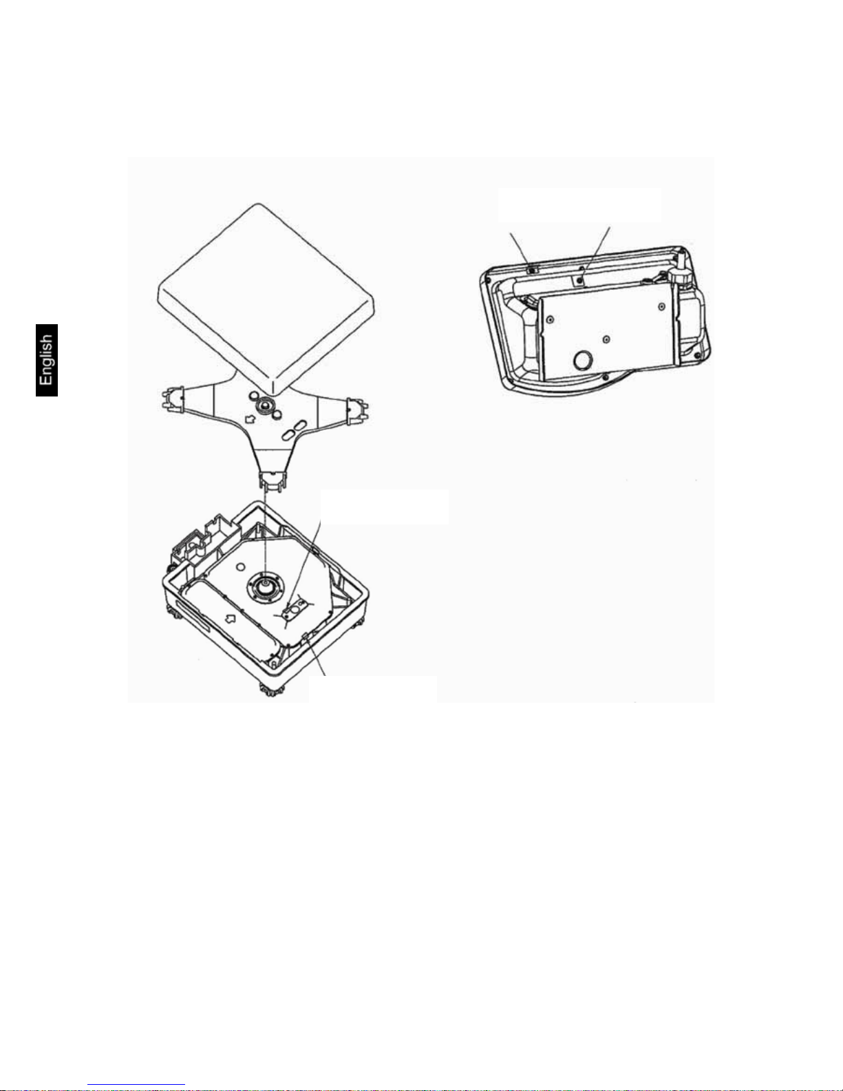
6.4 Setup
1. Level balance with foot screws until the air bubble of the water balance is in
the prescribed circle.
2. Remove weighing plate
3. Release the knobs on the display holder almost completely
4. Suspend the display holder on the cable box from above
5. Turn in knobs completely in order to fix them
6. Draw the cable into the cable box, bend and store it, and let 15 cm remain
outside.
Cable box
Foot screws
Page 14

FES/FEJ-BA-e-1132
14
7. Apply the cable box cover from above, bending the sides slightly outwards.
8. Hold the display a little inclined upwards and slide the lateral guiding noses
under the lateral grooves of the display holder.
9. Re-install the weighing plate
Displa
y
Guidingnoses
Page 15

FES/FEJ-BA-e-1132
15
10. Insert the display holder cover from the top above the two knobs of the display
holder. It is locked in the groove on the display holder.
6.4.1 Assembly instructions for the use of the stand (option)
Cover
Groove
Cover
Page 16

FES/FEJ-BA-e-1132
16
Weighing plate
Cable box
Lateral view:
6.5 Mains connection
Power is supplied via the external mains power supply. The stated voltage value
must be the same as the local voltage.
Only use original KERN mains power supplies. Using other makes requires consent
by KERN.
Stand
Turn knob
Stand holder
Cover plate
Cable balance
Net adapter
Fastening screws
Page 17

FES/FEJ-BA-e-1132
17
6.6 Battery power supply
The optionally supplied battery is charged with the supplied power supply.
Before the first use, the battery should be charged by connecting it to the mains
power supply for at least 12 hours. The operating time of the battery is about. 6h.
Charging time until complete recharging ca. 12h.
In the menu you can activate the AUTO-OFF function [yA.P.1]. After 3 min without
load change the balance switches automatically off in order to spare the battery.
Whilst in battery mode the balance is IP 65 protected.
When the balance is in battery mode the following symbols appear on the display:
Battery charge sufficient
Battery very low. To charge the battery, connect it to the mains
as soon as possible (re-calibration not possible).
flashes
Voltage has dropped below prescribed minimum (7V). Plug in
the mains adapter, to charge the balance via the electrical network (12h).
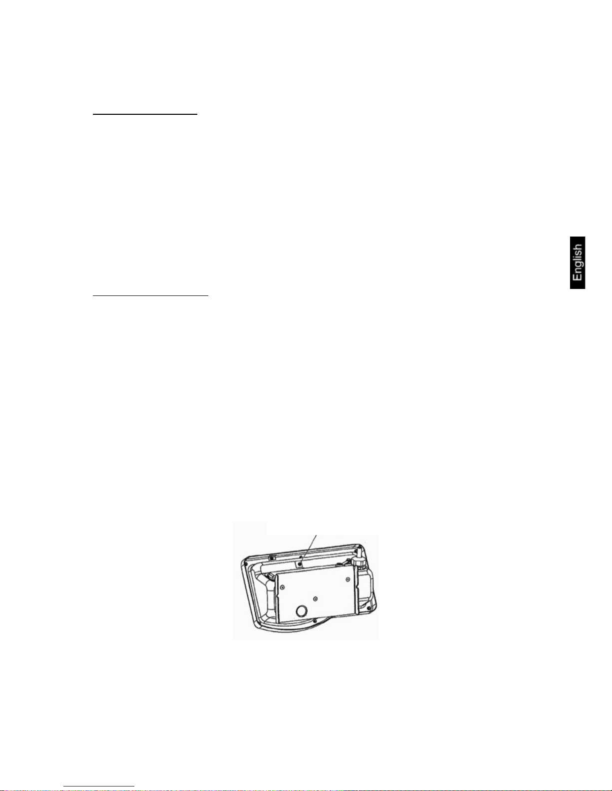
6.7 Terminal for external devices
The output for the external devices is situated under the cover plate on the rear of the
display. To detach the cover plate, remove the fastening screws (see fig.
chap. 6.5).
Caution: Doing this, the IP 65 protection provided in battery mode will be lost.
Printer interface
RS 232 interface
Page 18

FES/FEJ-BA-e-1132
18
6.8 Initial Commissioning
In order to obtain exact results with the electronic balances, your balance must have
reached the operating temperature (see warming up time chap. 1). During this warming up time, the balance must be connected to the power supply (mains, accumulator
or battery).
The accuracy of the balance depends on the local acceleration of gravity.
Please be sure to observe the information in the chapter on adjusting in chap. 6.8.
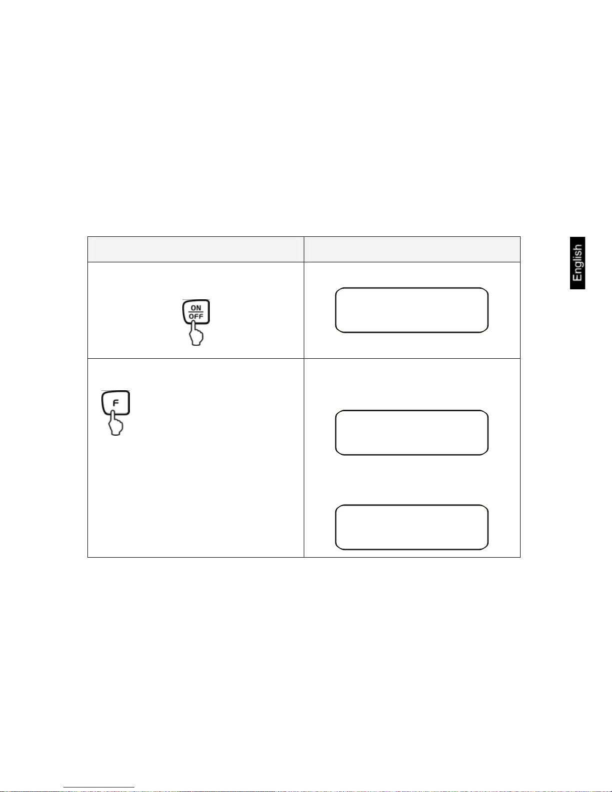
6.8.1 Power display
The balance will carry out a self-test
Supply balance with power via the
mains power supply.
Balance is in stand-by mode (green
LED is on).
Use the -key to switch the balance on.
Qn 0
If there is an object on the weighing
plate when the balance is switched
on there is a flashing display „on
0“. In that case, remove object
from the weighing plate.
a
z0
g
75s0
g
By pressing lightly it is possible to
check whether the balance display
changes.
Stand-by
Use the -key to switch the balance off. The balance is now in
stand-by mode again (green LED is
on).
Page 19

FES/FEJ-BA-e-1132
19
6.8.2 Bar graph display
weighing dish unloaded
half of weighing range
weighing range is used to full capacity
The weighing range of the balance is divided into 40 graphic cuboids. Zero (0) will
appear on the graphic display if there is no weighing value on the balance. 20 graphic
cuboids are displayed if the balance is loaded up to one half of its weighing range.
In configuration menu 1 (chapter 7) you can activate/deactivate the bar graph display.
Parameter selection:
0
Hide bar graph
xB.G.
* 1
Show bar graph
Bar graph display in the respective operating modes:
Bar graph display Operating mode
Weighing mode
Tolerance weighing with 1 or
2 limits
Tolerance weighing with 3 or
4 limits
NOTE:
If tare weighing is being carried out, the graphic weight display will continue to indicate the number of cuboids of the tare weight.
Page 20

FES/FEJ-BA-e-1132
20
6.8.3 Stability display
Stable
Unstable
If the display shows the stability display [ο] the balance is in a stable status. The [ο]
indication disappears if the condition is unstable.
Page 21

FES/FEJ-BA-e-1132
21
6.8.4 Balance zero display
Environmental influences can lead to the exact figure of “000.0“ not being displayed
in spite of an empty weighing dish. It is, however, possible to reset your balance to
zero at any time and thus ensure that weighing really does commence at zero. Setting to zero when a weight is applied is only possible within a certain type-dependent
range. In the event that the balance cannot be reset to zero with an applied weight,
this range has been exceeded.
[o - Err ] will appear on the display.
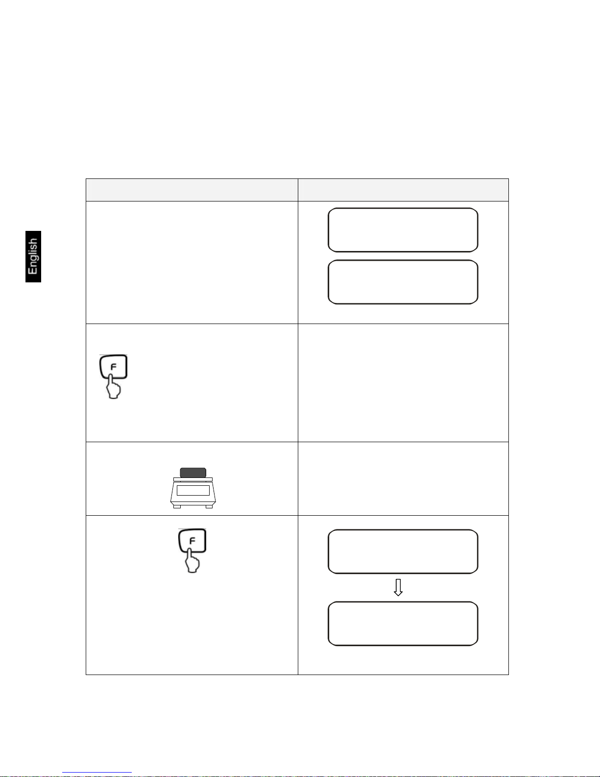
Operation Display
If the balance does not show exactly zero
although the pan scale is unloaded, press the
-button and the balance will be reset to
zero.
After a brief waiting time your balance is
reset to zero.
In addition to this, the sign for the balance
zero setting will be displayed [→0←].
a
z0
g
6.9 Adjustment
As the acceleration value due to gravity is not the same at every location on earth,
each balance must be coordinated - in compliance with the underlying physical
weighing principle - to the existing acceleration due to gravity at its place of location
(only if the balance has not already been adjusted to the location in the factory). This
adjustment process must be carried out for the first commissioning, after each
change of location as well as in case of fluctuating environment temperature. To receive accurate measuring values it is also recommended to adjust the balance periodically in weighing operation.
6.9.1 Adjustment with external weight (only FES)
Procedure when adjusting:
Observe stable environment conditions. A warming-up time (see cap. 1) for stabilisation is necessary. Ensure that there are no objects on the weighing plate.
At verified balances, the adjustment is locked by a switch. In order to adjust, open the
locking switch see chap.6.11.
Page 22

FES/FEJ-BA-e-1132
22
Operation Display
Activate function [w CA. 3] (see chap. 7).
wCA3
Ø
a
z0
g
Zero point will be saved.
CAL EH T
CAL
K
Ø
Qn
O
CAL
If the display indicates [ PuSH. F ],
press the -key
Carefully place adjusting weight in the centre
of the weighing plate
Adjustment process is started.
The process of adjustment is completed.
Remove adjusting weight, balance will return
into weighing mode automatically. In case of
an adjustment error or incorrect adjusting
weight the display will show [- Err]; repeat
adjustment process.
Qn
F.5.
CAL
Ø
If the display indicates [ PuSH. F ],
press the -key
Qn
F.5.
CAL
Ø
BWSX
Ø
EnD
CAL
Ø
a
z0
g
Page 23

FES/FEJ-BA-e-1132
23
6.9.2 Adjustment test with external weight (only FES)
During adjustment tests the balance automatically compares the saved value of the
adjustment weight with the actual value. This is only a check, i.e. no values are
changed.
Procedure:
Observe stable environmental conditions. A warming up time (see chap. 1) is required for stabilization. Ensure that there are no objects on the weighing plate.
Operation Display
Activate function [w CA. 4]
(see chap. 7).
wCA4
Ø
a
z0
g
Start of the adjustment test:
Carefully place adjusting weight in the
centre of the weighing plate
The difference between the saved value
and the measured value is displayed.
CAL EH T
CAL
K
Ø
Qn
O
CAL
Ø
If the display indicates [ PuSH. F ], press
the
-key
Qn
F.5.
CAL
Ø
If the display indicates [ PuSH. F ], press
the -key
Qn
F.5.
CAL
Ø
Page 24

FES/FEJ-BA-e-1132
24
Take away adjustment weight.
Press any key; the adjustment process is
cancelled and the balance returns to
weighing mode.
D KFF
Ø
-z02
g
Ø
EnD
CAL
Ø
a
z0
g
Page 25

FES/FEJ-BA-e-1132
25
6.9.3 Adjustment with internal weight (only FEJ)
With the internal adjustment weight, the weighing accuracy can be checked and readjusted at any time.
Procedure when adjusting:
Observe stable environmental conditions. A warming-up time (see chap. 1) for stabilisation is necessary. Ensure that there are no objects on the weighing plate.
Position of the verifying switch to the right (verifying position).
Operation Display
Activate function [w CA. 1]
(see chap. 7).
wCA1
Ø
a
z0
g
Start of the automatic adjustment:
Adjustment is carried out automatically.
The process of adjustment is completed.
The balance returns automatically into
weighing mode.
AUTO CAL
CAL
Ø
CH. 0
K
CAL
Ø
CH. F.5.
K
CAL
Ø
BWSX
Ø
EnD
CAL
Ø
a
z0
g
Page 26

FES/FEJ-BA-e-1132
26
6.9.4 Adjustment test with internal weight (only FEJ)
During adjustment tests the balance automatically compares the saved value of the
adjustment weight with the actual value. This is only a check, i.e. no values are
changed.
Procedure:
Observe stable environmental conditions. A warming up time (see chap. 1) is required for stabilization. Ensure that there are no objects on the weighing plate.
Operation Display
Activate function [w CA. 2]
(see chap. 7).
wCA2
a
z0
g
Start of the adjustment test:
The test is carried out automatically.
T. KnT
CAL
T.
0
CAL
T. F.5.
CAL
Page 27

FES/FEJ-BA-e-1132
27
The difference between the saved value
and the measured value is displayed.
Press any key; the adjustment process is
cancelled and the balance returns to
weighing mode.
D KFF
-z02
g
EnD
a
z0
g
Error messages during adjustment function:
1. 3-Err: The weighing plate is not empty -> Remove goods to be weighed from
weighing plate
2. 7-Err: Battery capacity too low -> connect balance to power adapter
(load battery)
Should other error messages occur, switch balance off and then on again. If the error
message remains inform manufacturer.
Page 28

FES/FEJ-BA-e-1132
28
6.10 GLP Log
Quality assurance systems require printouts of weighing results as well as of correct
adjustment of the balance stating date and time as well as balance identification. The
easiest way is to have a printer connected.
Activate function (E.GLP – 1), see chap.7
Printout example:
DATE 04.11.2008
Date
TIME: 08:42
Time
GOTTL.KERN&SOHN
Company
TYPE FEJ33K01IPM
Model
S/N Dxxxxxxxxx
Serial no.
ID 1234
Balance identification no.
CAL.INTERVAL
REF:
033000.0 g
Adjustment weight
COMPLETE
DATE: 04.11.2008
TIME: 08:42
SIGNATURE
prepared by
****************************
Page 29
FES/FEJ-BA-e-1132
29
6.11 Verification
General introduction:
According to EU directive 90/384/EEC balances must be verified if they are used as
follows (legally controlled area):
a) For commercial transactions if the price of goods is determined by weighing
b) For the production of medicines in pharmacies as well as for analyses in the
medical and pharmaceutical laboratory
c) For official purposes.
d) For manufacturing final packages.
In cases of doubt, please contact your local trade in standard.
Verification instructions
An EU type approval exists for balances described in their technical data as verifyable. If a balance is used where obligation to verify exists as described above, it must
verified and re-verified in regular intervals.
Re-verification of a balance is carried out according to the respective national regulations. The validity for verification of balances in Germany is e.g. 2 years.
The legal regulation of the country where the balance is used must be observed!
6.12 Verification switch and seal
The calibration switch is located on the back of the display. Access to the calibration
switch by removing the seal and the rubber plug (see drawing). Prior to calibrating,
the calibration switch must be moved into the calibration position.
• Position left: enabled
• Position right: Calibration position
Position calibration switch
Page 30
FES/FEJ-BA-e-1132
30
After verification the balance is sealed at the indicated positions.
Verification of the balance is invalid without the "seal".
Position of the “official seals“:
Balances with obligation to verify must be taken out of operation if:
- The weighing result of the balance is outside the error limit. Therefore,
in regular intervals load balance with known test weight (ca. 1/3 of the max.
load) and compare with displayed value.
- The reverification deadline has been exceeded.
Seals
Seal
Seal
Page 31
FES/FEJ-BA-e-1132
31
7 Application and configuration menu 1
In the menu the settings of the balance can be modified and functions can be activated. This way, the balance can be adjusted to individual weighing requirements.
The menu is structured as follows
Ö Application menu: To adjust the balance to user requirements
Ö Configuration menu 1: Definition of the basic functions
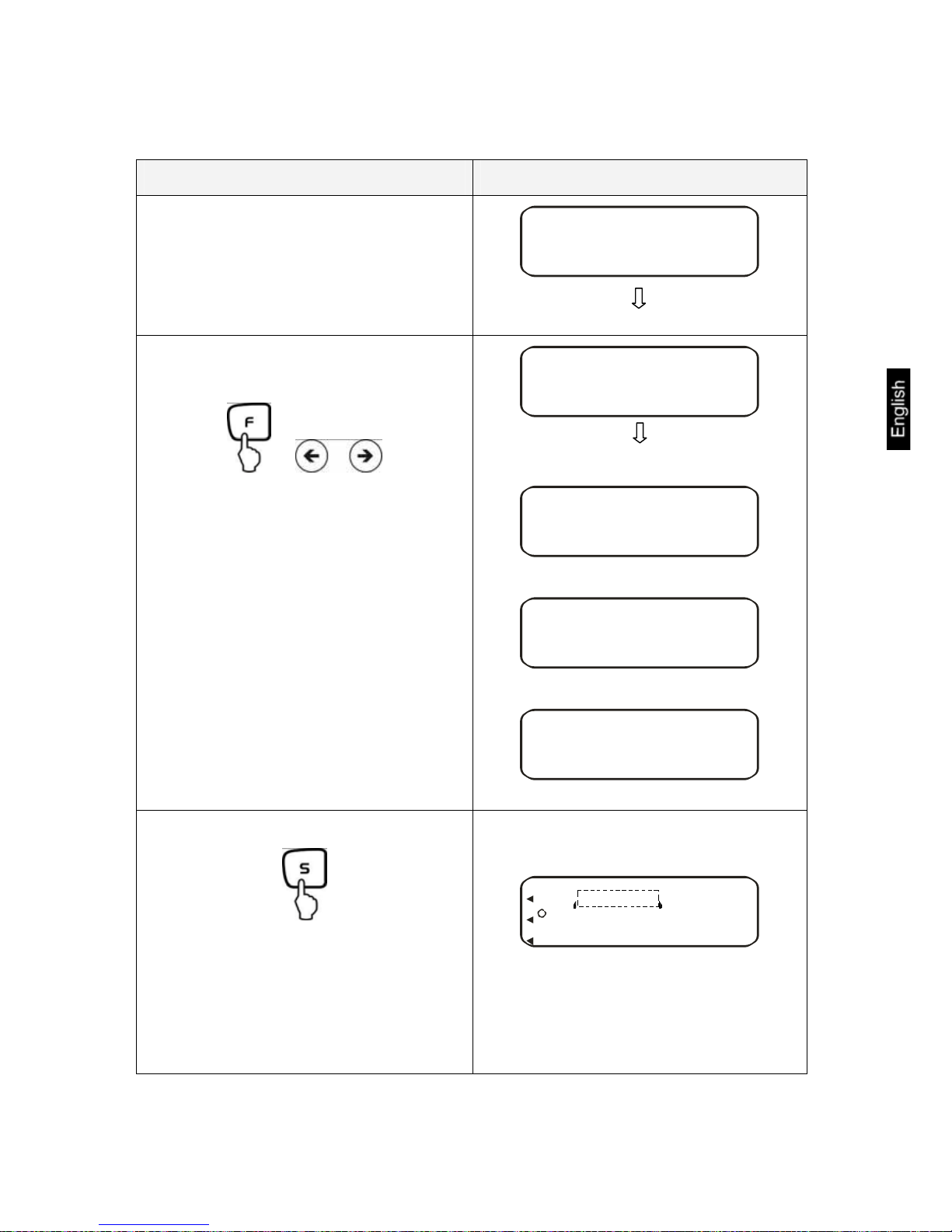
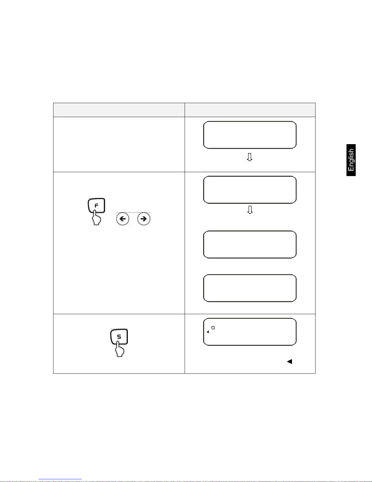
7.1 User principle of the menu control
Operation Display
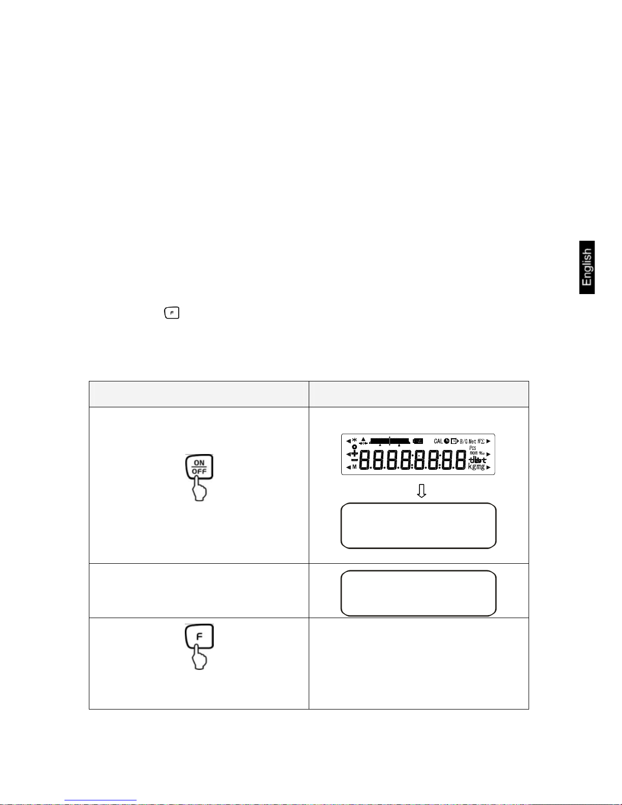
Switch on balance:
a
z0
g
Call up menu:
Press for about 4 seconds, until
[FWnm] is displayed.
Fonm
When releasing, the first function is displayed [q SET1 ].
qSET1
Page 32
FES/FEJ-BA-e-1132
32
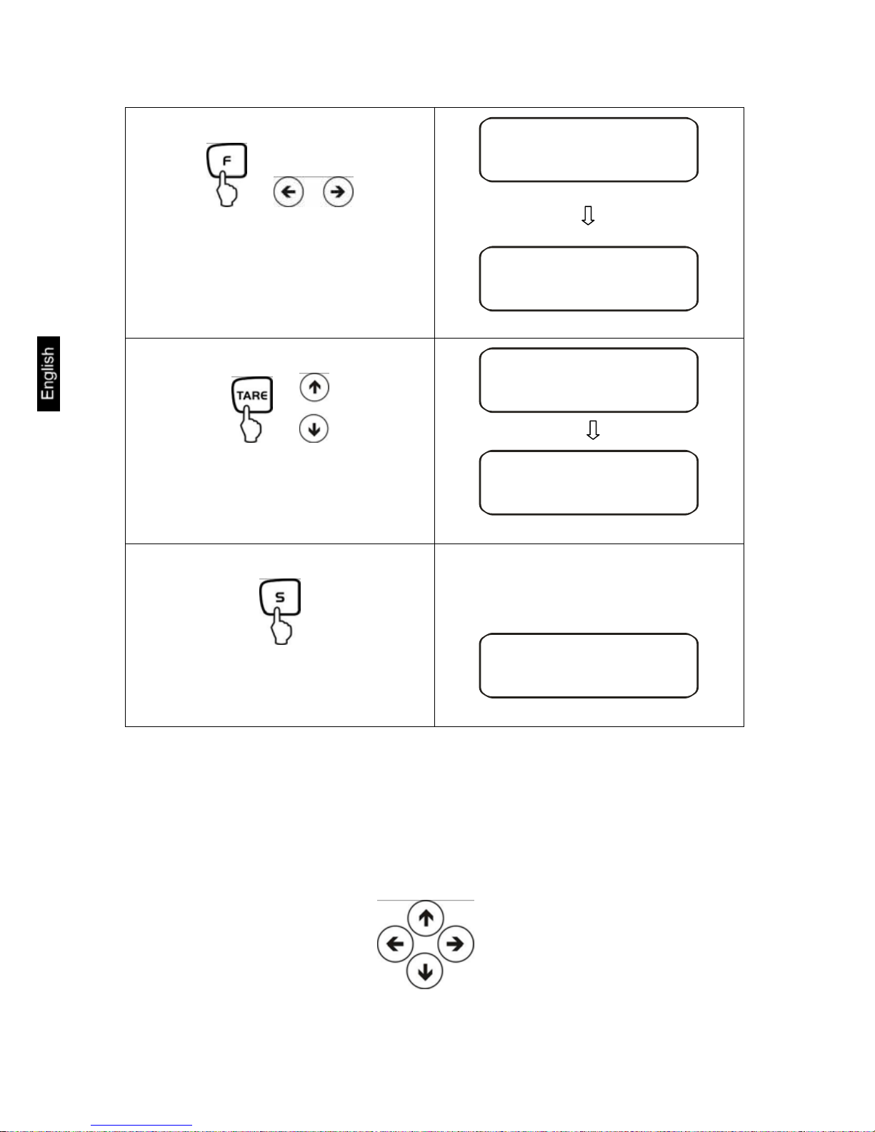
Changing the function:
or
Further pressing the keys will call up the
various functions of the menu (see table
chapter 7.2)
qSET1
rSEL0
Changing the parameter:
or
To change the last digit of the parameter,
actuate the TARE-key or the arrow keys.
rSEL0
rSEL3
Saving your settings:
Leave the function menu and return to
weighing mode
a
z0
g
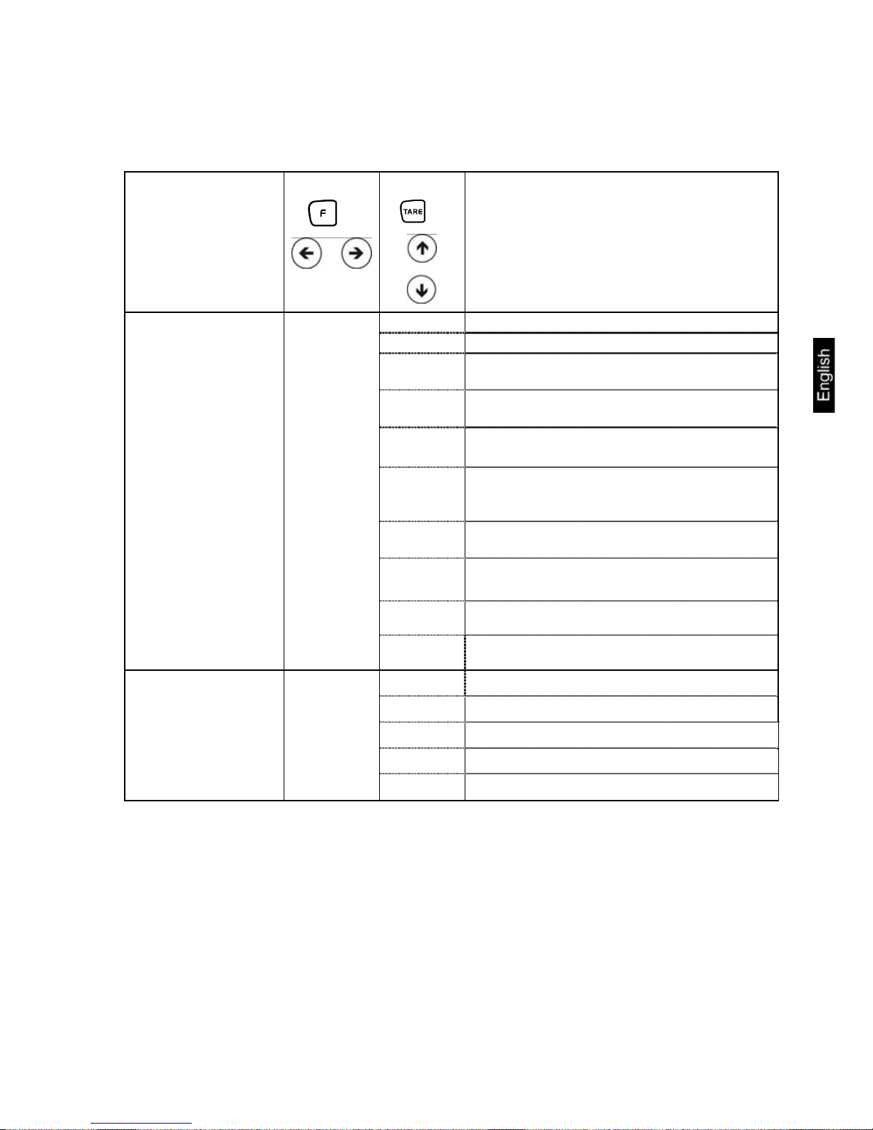
General information about using the arrow keys for entering:
Operation via arrow keys is faster and more comfortable than via the TARE and F
key.
Key allocation of the arrow keys:
Increase numeral value
Menu step back
Menu step forward
Decrease numeral value
Page 33

FES/FEJ-BA-e-1132
33
7.2 Menu overview
The manufacturer’s setting has a certain standard configuration. This one is marked
with *.
Function Display
or
Selectio
or
Description of the
options
* 1
Weighing
2
Combination: Weighing/parts counting
Weighing mode
q SET.
3
Combination: Weighing/percent determination
* 0
Off
1
Add
2
Tolerance weighing
Additional functions
r SEL
3
Combination Tolerance
weighing/adding
see chapter
12.3, Tab. 1
0
No zero balancing
Zero balancing
sA.O
* 1
Automatic zero balancing is activated.
* 2
3
Vibration filter
t S.D.
4
Sensitive and fast (very quiet set-up location).
ª
Robust but slow (very busy set-up location)
0
Setting for dispensing: Sensitive and fast
1
2
ª
Display speed
u RE.
* 3
Insensitive but slow
0
Deactivated
* 1
6-digit data format
2
7-digit data format
see chap. 15.4.1
Interface
(see chpt. 7.2.1)
vK.F.
3
extended 7-digit data
format
not documented
0
CAL-key turned off
*1 1
Automatic internal adjustment (only FEJ)
2
Adjustment test with internal weight
(only FEJ)
*2 3
External adjustment
Adjustment
* 1: Factory setting FEJ
* 2: Factory setting FES
w CA.
4
Adjustment test with external weight
Page 34

FES/FEJ-BA-e-1132
34
0
Hide bar graph
Bar graph
xB.G.
* 1
Show bar graph
0
Automatic turn-off for battery operation
(optional) - off.
Automatic turn-off for battery operation (function
only exists for battery operation)
yA.P.
* 1
Automatic turn-off for battery operation
(optional) - on.
0
Off
Auto Sleep
A. A.u
* 1
3 minutes after connecting balance to
power supply it will go into sleep mode
* 1
(g)
2
(kg)
Units A
BK. W.A
4
(ct)
* 0
No unit
1
(g)
2
(kg)
Units B
B3. W.B
4
(ct)
0
no
Display last fractional digit
.C .A.1.
* 1
Yes; always use this setting!
no
Multiple range
C. D.R
0
Yes
Only for model
FES/FEJ62 K0.1 DIPM
* 0
no
E. GLP
1
Yes
0
no
Eq QWT
* 1
Yes
* 0
no
E2. QD.
1
Yes
* 1
English
In accordance with
ISO/GLP/GMP
Not documented
E3. P.F.
2
not documented
1
Display in year-month-day
2
Display in month-day-year
Date
F. DATE
* 3
Display in day-month-year
* 0
Output - NO
Time
G. T.Q.
1
Output - YES
* 0
When connecting the mains cable, the
balance will immediately go into stand-by
mode
Immediate start
L. D.ST.
1
Balance switches on when plugging in
mains power supply
1
not documented
2
not documented
Output interface
n. PRF.
* 3
not documented
Page 35
FES/FEJ-BA-e-1132
35
7.2.1 Parameter for serial interface
Not shown for menu setting „vK.F0“ (interface de-activated).
Function Display
or
Selectio
or
Description of the
options
0
No data output
1
Continuous data output
2
Continuous data output stable weighing values
3
Output for stable and instable weighing values after pressing PRINT key
4
Output for stable weighing value after previous relief of balance
5
One output for stable weighing value. No
output for stable weighing values. Renewed
output after stabilization
6
One output for stable weighing value. Continuous output for instable weighing values.
* 7
Output of stable weighing values after pressing PRINT key
A
Single, immediate output after fixed interval
(see chpt. 14.5)
Output condition at
interface
61. Q.m.
B
Single, immediate output after fixed interval
and stable weighing value (see chpt 14.5)
* 1
1200 bps
2 2400 bps
3 4800 bps
4 9600 bps
Baud rate
6r B.L.
5
19200 bps
Page 36

FES/FEJ-BA-e-1132
36
* 0
No parity bit
1
Odd parity
Parity
only at setting
vK.F.2or
vK.F.3
6s PA.
2
Even parity
* 7
7 bits
Data Bits
only at setting
vK.F.3
6t D.L.
8
8 bits
1
1 bit
Stop Bits
only at setting
vK.F.3
6u ST.
* 2
2 bit
* 0
Always use this setting
not documented
66 W.N.
1
* 1
Always use this setting
not documented
6w RES.
2
Page 37

FES/FEJ-BA-e-1132
37
8 Configuration menu 2
8.1 User principle of the menu control
Operation Display
Switch on balance:
a
z0
g
Call up menu:
+
Hold F-key while TARE key is pressed
until [FWnm 2] is displayed.
Fonm2
When releasing, the first function is displayed [K. KD. O]
qKD0
Changing the function:
or
Further pressing the keys will take you
through the various functions of the
menu.
qKD0
rR.CA.0
Page 38

FES/FEJ-BA-e-1132
38
Changing the parameter:
or
To change the last digit of the parameter
actuate TARE-key or arrow keys.
qKD0
qKD1
Saving your settings:
Leave the menu and return to weighing
mode
a
z0
g
8.2 Menu overview
The manufacturer’s setting has a certain standard configuration. This one is marked
with *.
Function Display
Choice
Description of the
options
*0
Off
Setup balance ID no.
1. 1D
1
On
*0
Off
Overwriting the adjusting
weight
Caution:
Modifications may only
be carried out by specialized personnel!
2. R.CA
1
On
Page 39

FES/FEJ-BA-e-1132
39
9 Operation
9.1 Keyboard overview
Choice Function
• Turn on/off
• Output of the weight value on an external device
(printer) or PC
• Save function parameters
• Addition of displayed values in addition memory
• Menu call up "Enter tolerance limits"
• Switching the displayed value (g, ct, Pcs, %)
• Entering numeric values
• Choosing the function values within the function
• Call up individual functions (multiple print)
• The entry point will be shifted one spot to the left
• Tare or set weight display to zero
• Individual setting within the individual function
• Changing the parameters
• Start internal adjustment
• For may entering functions, the arrow keys replace the
or keys (see chapter 7.1)
LED (green)
• "Stand-by" glows if the balance is operated with energy
from the power mains but turned off.
LED (red)
• "Sleep" has the function of a display saver. It can be de-
activated by actuating a key or changing the load.
Page 40

FES/FEJ-BA-e-1132
40
9.2 Overview of display
Display Description
g, kg Gram, Kilogram
→0←
Zeroing display
- Minus
ο Stability display
Net Net weight
B/G Gross /gross weight
Pcs Parts counting
% Percent weighing
Tolerance weighing
* Adding function active
∑ Total
L
Output date/time
M
Balance carries out balance function, e.g. unit count / display of
stored value
CAL Display for adjustment. Signals the adjustment function.
Weighing unit display
Bar graph
Message for battery mode (optional) see chap. 6.6
Display last fractional digit
Page 41
FES/FEJ-BA-e-1132
41
10 Weighing mode
The manufacturer’s standard configuration is "Weighing":
Function [q SET.1], see chapter 7.2.
Under this menu item, you can combine the function "Weighing" with the function
“Parts counting” or “Percent determination” (settings see chapter 7.2).
This way, 3 different weighing modes are available for you:
1. Weighing [q SET.1]
2. Weighing/parts counting [q SET. 2]
3. Weighing/percent determination [q SET. 3]
Apart from selecting a weighing mode, you can activate other functions (Tolerance
weighing, adding); see chapter 7. This enables you to display your measuring values
according to your requirements.
Actuating the key will switch the displayed value to the active function (e.g. "g" to
"Pcs").
10.1 Weighing
Operation Display
Switch on balance:
Your balance is ready to weigh as soon
as the “0.0" display appears.
The balance will carry out a self-test
:
a
z0
g
Put on items to be weighed, weighed
value is displayed.
a
75s0
g
By repeated pressing, switching option of
the displayed value into other activated
functions/weighing units
Page 42
FES/FEJ-BA-e-1132
42
10.1.1 Taring
The dead weight of any weighing container may be tared away by pressing a button,
so that the following weighings show the net weight of the goods to be weighed.
Operation Display
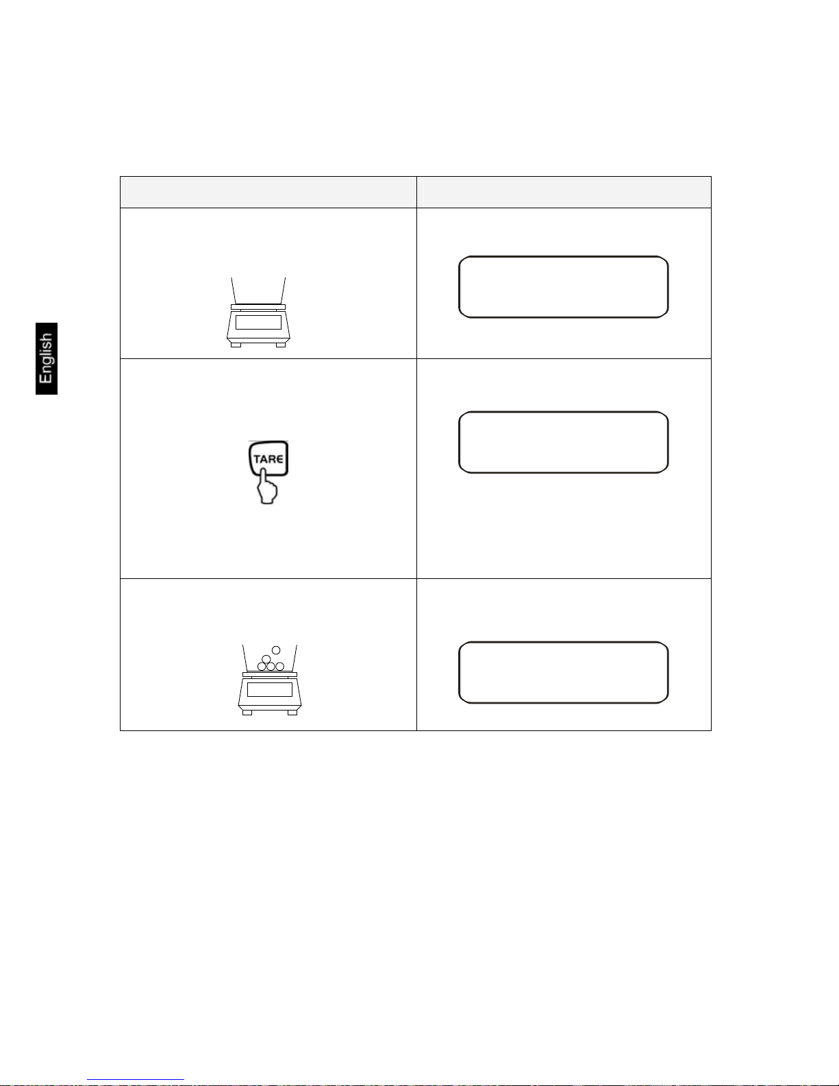
Place empty tare container on the weighing plate. The total weight of the container is displayed.
75s0
g
Reset display to "0":
z0
g
Net
The weight of the container is now saved
internally; in addition the display shows
the tare symbol "Net".
Place the goods to be weighed into the
tare container.
Read the weight of the goods on the display.
153z0
g
Net
Page 43
FES/FEJ-BA-e-1132
43
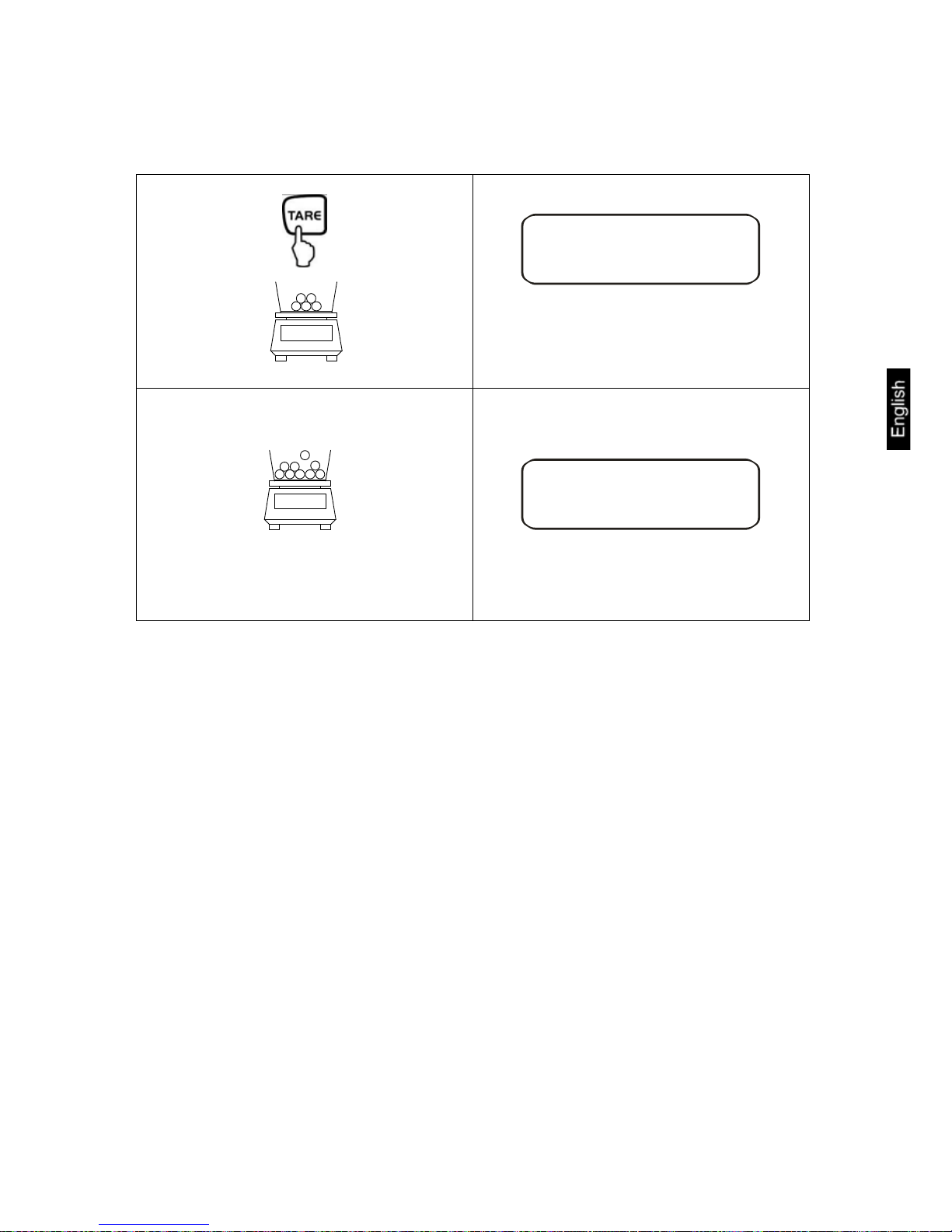
The taring process can be repeated any number of times, e.g. when adding several
components for a mixture (adding).
Reset display to "0":
z0
g
Net
The total weight of the container is tared
away.
Add more components into the weighing
container (adding).
Now read off the weight of the added
item to be weighed on the display.
457z9
g
Net
NOTE:
The balance is able to only store one taring value at a time.
When the balance is unloaded the saved taring value is displayed with negative
sign.
Remove all items from the weighing plate in order to delete the stored tare value
and subsequently press the TARE key.
The taring process can be repeated any number of times. The limit is reached
when the whole weighing range is exhausted.
Page 44

FES/FEJ-BA-e-1132
44
10.1.2 Net/gross
The dead weight of any weighing container may be tared away by pressing a button.
For subsequent weighings the net weight of the goods to be weighed as well as the
gross weight goods + taring container can be displayed.
Condition:
• Function [q SET.1] active (see chapter 7)
Operation Display
Place empty tare container on the weighing plate. The total weight of the container is displayed.
100z0
g
Reset display to "0":
z0
g
Net
The weight of the container is internally
stored, the display shows the tare symbol "Net".
Place the goods to be weighed into the
tare container.
The net weight of the goods to be
weighed is displayed.
250z0
g
Net
The gross weight (goods + taring container) is displayed, the display shows
the gross symbol "B/G".
350z0
g
B/G
Page 45

FES/FEJ-BA-e-1132
45
Use the F key to switch from net weight
to gross weight or vice versa
This procedure may be repeated any
number of times (max. weighing range of
the balance).
250z0
g
Net
350z0
g
B/G
10.2 Weighing/parts counting
With parts counting you can either count parts into a container or remove parts from
a container. To count a greater number of parts the average weight per part has to
be determined with a small quantity (reference quantity). The larger the reference
quantity, the higher the counting exactness. High reference must be selected for
small parts or parts with considerably different sizes.
The process has four steps:
• Tare the weighing container
• Determine the reference unit
• Weigh in the reference unit
• Count the items
Operation Display
Activate function [q SET. 2]
(see chapter 7).
The display shows the reference quantity
symbol "Pcs".
qSET2
z0
Pcs
If you are using a weighing con-
tainer
Page 46

FES/FEJ-BA-e-1132
46
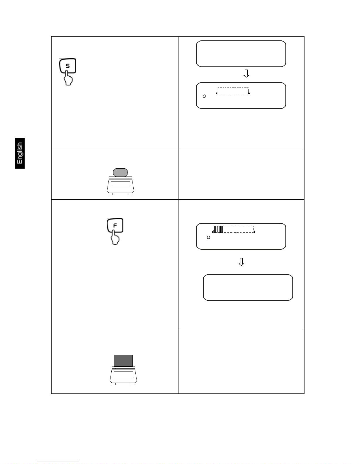
Determine the reference unit:
Press for about 4 seconds, until
[U. SEt.] is displayed, then
release
The display shows flashing the last
saved reference quantity.
Qn 10
Pcs
M
The display e.g. 10 Pcs. prompts
you to enter 10 pieces as reference.
Change reference quantity:
or
Use the TARE-key or the arrow keys to
switch between the following reference quantities:
Important: The larger the reference quantity,
the more accurate the parts counting.
Qn 30
Pcs
M
Weigh in the reference unit:
Place as many parts to count on the balance
as the set reference quantity requires.
The reference quantity is displayed
flashing.
30
Pcs
The balance offers the possibility of
reference optimizing. If this is not
desired, press the F key.
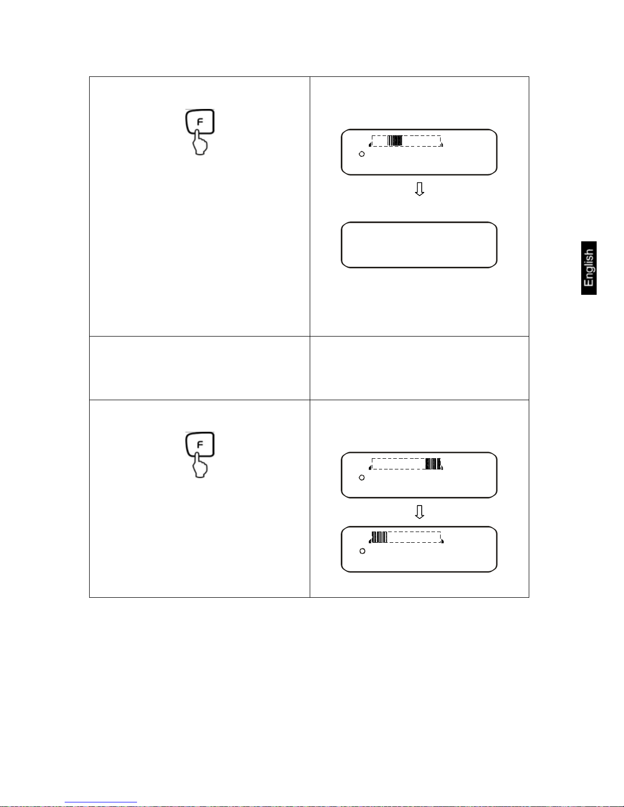
Reference optimization:
By adding more pieces (up to the 3-fold
quantity), you can optimize the reference. At
every reference optimization, the reference
weight is calculated anew. As the additional
pieces increase the base for the calculation,
the reference also becomes more exact.
60
Pcs
10
5 30
100
Page 47

FES/FEJ-BA-e-1132
47
The reference weight is saved.
Remove reference weight.
EnD
60
Pcs
Count the items:
Now you can fill the items to be counted
into the container. The respective quantity is shown in the display.
50
Pcs
By repeated pressing, switching option
of the displayed value of the displayed
value e.g. in:
• Number of parts placed on balance
"Pcs"
• Average part weight "g/Pcs"
• Weight of parts placed on balance in
"g"
50
Pcs
20.00001
Pcs
g
100z0
g
NOTE:
• If the error message "Sub" appears, the triple quantity has been exceeded.
• If the error message “L-Err “ appears the smallest counting weight has not been
reached.
• If the “Add“ error message appears, the applied number of items is too small for
correct determination of the reference. For reference, place more parts on the
balance.
Page 48
FES/FEJ-BA-e-1132
48
10.3 Weighing/percent determination
Percent weighing allows to display weight in percent, in relation to a reference
weight. The displayed weighing value is stored as a standard percent value
(default setting: 100%).
10.3.1 Entering the reference weight by weighing
Operation Display
Activate function [q SET 3]
(see chap. 7).
The display shows the %-symbol.
qSET3
z0
%
Determine reference weight:
Press for about 4 seconds, until
[P. SET] is displayed, then
release
The display shows flashing the last
saved reference weight
Put on reference weight (=100 %)
An acoustic signal sounds; the reference
weight is saved.
Remove reference weight.
EnD
10z0
%
Page 49

FES/FEJ-BA-e-1132
49
From now, the added weight
is shown in %.
7y0
%
By repeated pressing, switching option of
the displayed value in „g“ or %“
59t8
g
7y0
%
NOTE:
• If the error message “o-Err “ is displayed, the reference weight is outside the
weighing range
• The 100% reference is preserved until the balance is disconnected from the
mains.
10.3.2 Numeric entering of the reference weight
Operation Display
Activate function [q SET 3]
(see chap. 7).
The display shows the %-symbol.
qSET3
z0
%
Determine reference weight:
Press for about 4 seconds, until
[P. SET] is displayed, then
release
The display shows flashing the last
saved reference weight
Page 50

FES/FEJ-BA-e-1132
50
0
g
With "0" flashing, you are prompted to
enter the reference weight numerically
Entering the numeric value:
or
⇒i⇒
0
1
⇒⇒⇒⇒≈
2
9
Any time you press TARE-key or the arrow key, you will go through the numbers
0-9, decimal dot and minus
Select the number to be changed (the
active position flashes):
or
An acoustic signal sounds; the entered
reference weight is saved
EnD
z0
%
Page 51

FES/FEJ-BA-e-1132
51
From now, the added weight
is shown in %.
7y0
%
By repeated pressing, switching option of
the displayed value in „g“ or %“
59t8
g
7y0
%
NOTE:
• If the error message “o-Err “ is displayed, the reference weight is outside the
weighing range
• The 100% reference is preserved until the balance is disconnected from the
mains.
Page 52

FES/FEJ-BA-e-1132
52
11 Adding of displayed values
Any number or individual weighings are automatically added to a total, e.g. all individual weighings of a batch.
The add function is possible in all functions of the weighing mode (Weighing/parts
counting/ percent determination).
Operation Display
1. Activate function [2 SEL 1]
(see chap. 7).
rSEL1
a
z0
g
2. Place the weight A, wait until the
stability display [|] appears
85z0
g
3.
The displayed value is added into the
total adding memory.
The total [ ∑ ] is briefly shown
85z0
g
∑
4. Remove weight.
As soon as the symbol [À] appears further weights can be placed on the balance
z0
g
5. Wait until the balance zero display is
shown, then place weight B on balance
Page 53

FES/FEJ-BA-e-1132
53
6. Wait until stability display is shown
[|] :
The displayed value is added into the
total adding memory.
The total [ ∑ ] is briefly shown
15z0
g
100z0
g
∑
15z0
g
Remove weight and place further
weights on balance; for each weight, repeat step 4 to 6
z0
g
7. Total of all individual weighings:
By repeatedly pressing the F-key, switching of the displayed value into other activated functions.
z0
g
170z0
g
∑
8. Delete total added memory:
Display total (step 7), then press
TARE-key.
z0
g
∑
Adding of displayed values is possible without removing the weight. To do so, in step
4 press Tare-key instead of removing the weight.
Page 54

FES/FEJ-BA-e-1132
54
12 Weighing with tolerance range
12.1 General Information
This balance can be used as dispensing as well as sorting balance; the respective
lower tolerance limit as well as upper tolerance limit can be programmed. An acoustic
signal supports portioning, dispensing or sorting.
• In the menu, (see chapter 7) activate the tolerance weighing function:
[2.SEL.2]
or the combination tolerance weighing/adding (tolerance control on the respective poured quantity):
[2. SEL.3]
Entering limits is possible for the following functions:
• Weighing
• Parts counting
• Percent determination
There are several functions available for tolerance control of the balance KERN FEJ.
There are two different ways to carry out evaluation of limits:
1. Evaluation of absolute values [24. TXP.1]:
An exact reference value (e.g. 1 kg) is set.
2. Evaluation with difference values [24. TXP.2]:
An upper limit and a lower limit for a reference value are set.
Example:
Reference
value
Lower limit Upper limit
Poured quantity 1,000.0 g 970.0 g 1,050.0 g
Evaluation of absolute values
1,000.0 g 970.0 g 1,050.0 g
Evaluation with difference values
1,000.0 g -30.0 g 50.0 g
Page 55
FES/FEJ-BA-e-1132
55
There are two different ways to set the tolerance limits:
1. Place the values (object) on the balance -
> Save this value
2. Numeric entering of values -
> Enter the limits via keyboard.
NOTE:
Ö If a limiting value was set it remains saved until the balance is turned off.
Ö For the functions weighing, counting, percent individual limits can be set.
Ö When entering the limits please pay attention to the type of evaluation that was set.
12.2 Display of the results
12.2.1 For 2 limits
The triangular tolerance marker ( ) in the upper part of the display shows whether
the goods to be weighed are within the two tolerance limits.
The tolerance marker is only in operation during operating mode tolerance weighing;
it is otherwise not visible.
The tolerance marker provides the following information:
Goods to be weighed above tolerance limit
Goods to be weighed within tolerance range
Goods to be weighed below tolerance limit
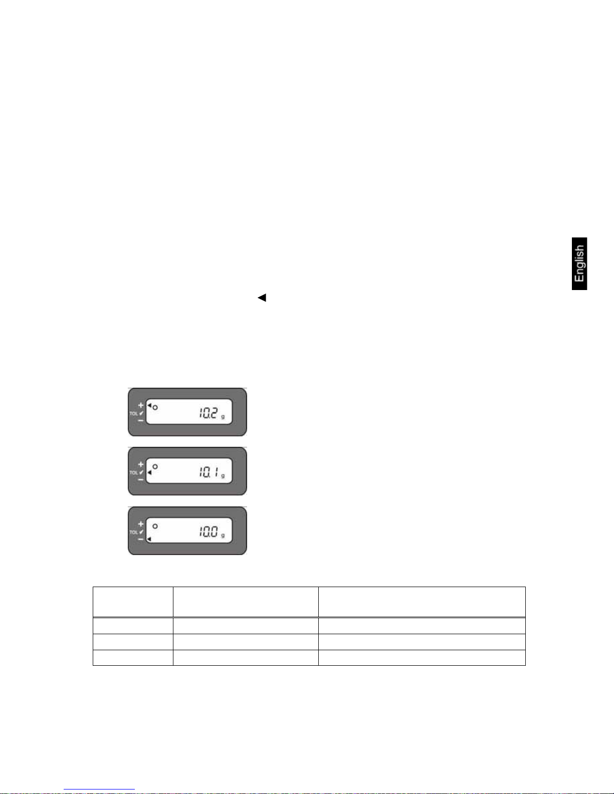
Display
Result
If a point is set as lower
limit
If two points are set as upper and
lower limit
+ (high)
No display Weight > Upper limit
TOL 3 (OK)
Lower limit ≤ Weight Lower limit ≤Weight ≤ Upper limit
- (low)
Lower limit > Weight Lower limit > Weight
Page 56

FES/FEJ-BA-e-1132
56
12.2.2 For 3 or 4 limits
If 3 or 4 limiting points are to be set, this is displayed in the bar graph. The length of
the represented bars indicates where within the tolerance range the weighed of the
goods to be weighed are.
12.3 Basic settings for weighings with tolerance range
Operation Display
1. Activate tolerance weighing function
[2.SEL.2] or [2.SEL.3] (see chap. 7).
rSEL2
2. Selection of tolerance parameters
or
Any time you press the F-key you can
select between the following settings,
see tab. 1.
2q CQ. 1
The first parameter for setting the tolerance marker appears.
3. Changing the parameter value
or
2q CQ. 1
2q CQ. 2
A bar graph shows the different limits.
4点設定
3点設定
Limit 5
Limit 4
Limit 3
Limit 2
Limit 1
4 Seg-
ments
3 Seg-
ments
Page 57

FES/FEJ-BA-e-1132
57
Tab. 1:
Function
Display
or
Selectio
or
Description of options
*1
Tolerance marker is always displayed,
even if standstill control is not yet displayed.
Display conditions of
the tolerance marker
21. CQ.
2
Tolerance marker is only displayed in
connection with standstill control.
0
Tolerance marker is only displayed
above zero range (mind + 5).
Tolerance range
22. LK.
*1
Tolerance marker is displayed for the
whole range.
1
1- Limiting point (OK/ -)
*2
2- Limiting points (+/OK/-)
3
3- Limiting points (1-4)
Number of limiting
points
23. P1
4
4- Limiting points (1-5)
*1
Evaluation for absolute values
Assessment
24. TXP
2
Evaluation for difference values (with
reference weight)
*0
No signal at limit 1(-)
Signal at limit 1
25. BW.K
1
Signal at limit 1 (-)
*0
No signal at limit 2(Ok)
Signal at limit 2
26. BW.2
1
Signal at limit 2(Ok)
*0
No signal at limit 3(+)
Signal at limit 3
27. BW.3
1
Signal at limit 3(+)
*0
No signal at limit
Signal at limit 4
28. BW.4
1
Signal at limit 4
*0
No signal at limit 5
Signal at limit 5
29. BW5
1
Signal at limit 5
*1
Display via +, OK or -
Display of Results
2A. LG
2
For setting 2 limits display in bar graph is
possible
Output setting
2B .R.Q.m.
Not documented
Page 58
FES/FEJ-BA-e-1132
58
12.4 Evaluation of absolute values
12.4.1 Entering 2 limits by weighing
Important information!
Always begin by entering the lower limit value, followed by the upper limit value.
Enter.
Operation Display
1. Activate tolerance weighing function
[2.SEL.2] or [2.SEL.3] (see chap. 7).
rSEL2
2. Actuate required parameter selection
or
until
[23. P1 .1] or [24. TXP.1] is displayed;
more settings of your choice (see tab.1,
chapter 12.3) are carried out in the same
way
2q CQ. 1
Parameter selection for 2 limiting points:
2s P . 2
1
Parameter selection for absolute value:
2t TXP. 1
3. Leave function menu
a
z0
g
The balance is now in tolerance weighing mode; the tolerance marker (
)
appears
Page 59
FES/FEJ-BA-e-1132
59
4. Entering limiting values:
Press for about 4 seconds, until
[L. SET] is displayed, then
release
L. SET
The flashing display (last saved value)
prompts you to enter the lower limiting
value (L.SET)
5. Place sample for the lower (i.e.
smaller) limiting value on the weighing plate:
6. Save:
An acoustic signal sounds, the saved
lower limit is briefly displayed.*
H. SET
K
The flashing display (last saved value)
prompts you to enter the upper limiting
value (
H. SET
K
)
Page 60

FES/FEJ-BA-e-1132
60
7. Place sample for the upper (i.e. larger) limiting value on the weighing
plate:
8. Save:
The balance returns to tolerance weighing mode.
From here evaluation takes place
whether the goods to be weighed are
within the two tolerance limits.
An acoustic signal sounds, the saved
upper limit is briefly displayed.
* If you want to set for your tolerance weighing only one limit point
(parameter selection [23. P1 .1]), ignore step 7 and 8.
Page 61
FES/FEJ-BA-e-1132
61
12.4.2 Entering 3 or 4 limits by weighing
Operation Display
1. Activate tolerance weighing function
[2.SEL.2] or [2.SEL.3] (see chap. 7).
rSEL2
2. Actuate required parameter selection
or
until
[23. P1 .1] or [24. TXP.1] is displayed;
more settings of your choice (see chap.
12.3) are carried out in the same way
2q CQ. 1
Parameter selection for 3 limiting points:
2s P . 3
1
Parameter selection for 4 limiting points:
2s P . 4
1
Parameter selection for absolute value:
2t TXP. 1
3. Leave function menu
a
z0
g
The balance is now in tolerance weighing mode; as a tolerance marker, the bar
graph is displayed.
Page 62
FES/FEJ-BA-e-1132
62
4. Entering limiting values:
Press for about 4 seconds, until
[L1 SET] is displayed, then
release
L1. SET
a
z0
g
The flashing display (last saved value)
prompts you to enter the first lower limit-
ing value (LK.SET)
5. Place sample for the first limiting
value on the weighing plate:
6. Save:
An acoustic signal sounds, the saved
first limiting value is briefly displayed.*
1z0
g
L2. SET
The flashing display (last saved value)
prompts you to enter the second limiting
value (L2.SET)
7. Place sample for the second limiting
value on the weighing plate:
Page 63
FES/FEJ-BA-e-1132
63
8. Save:
An acoustic signal sounds, the saved
second weighing value is briefly displayed.
1z0
g
L3. SET
The flashing display (last saved value)
prompts you to enter the third limiting
value (L3.SET)
9. To enter 3rd and 4th limiting value,
repeat steps 7 and 8
10. Save:
The balance returns to tolerance weighing mode.
From here, evaluation is carried out
whether the goods to weighed are within
the tolerance limits.
An acoustic signal sounds, the last
saved 3rd or 4th limiting value is briefly
displayed.
2z0
g
z0
g
Page 64

FES/FEJ-BA-e-1132
64
12.4.3 Numeric entering of 2 limits
Operation Display
1. Activate tolerance weighing function
[2.SEL.2] or [2.SEL.3] (see chap. 7).
rSEL2
2. Actuate required parameter selection
or
until
[23. P1 .1] or [24. TXP.1] is displayed;
more settings of your choice (see chap.
12.3) are carried out in the same way
2q CQ. 1
Parameter selection for 2 limiting points:
2s P . 2
1
Parameter selection for absolute value:
2t TXP. 1
3. Leave function menu
a
z0
g
The balance is now in tolerance weighing mode; the tolerance marker (
) ap-
pears
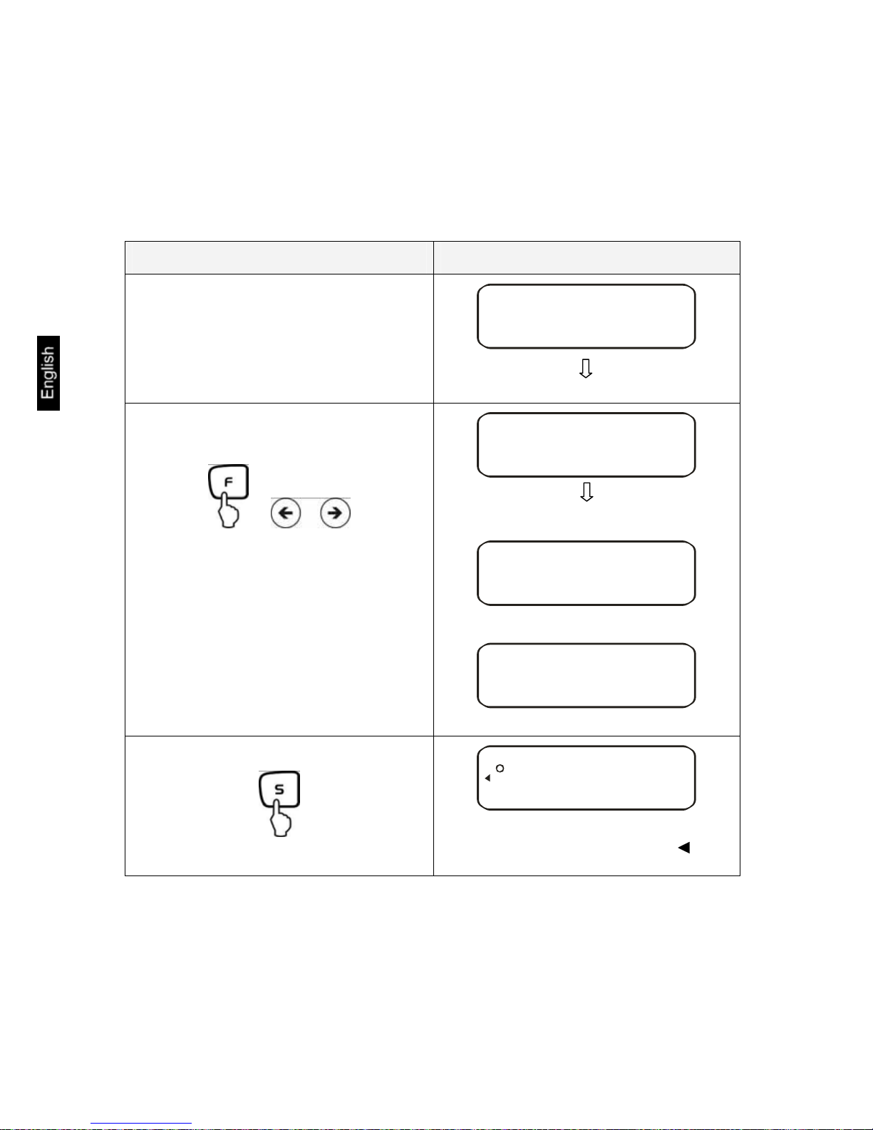
4. Entering limiting values:
Press for about 4 seconds, until
[L. SET] is displayed, then
release
L. SET
The last saved limiting value is displayed
flashing
Page 65

FES/FEJ-BA-e-1132
65
5.
Display changes to flashing "zero"
The flashing display prompts you to numerically enter the lower limit
6. Entering numeric value for the lower
limit
or
⇒i⇒
0
1
⇒⇒⇒⇒≈
2
9
Any time you press the TARE-key or the
arrow keys you will go through the numbers 0-9, decimal dot and minus
Select the number to be changed (the
respective active position flashes)
or
Page 66
FES/FEJ-BA-e-1132
66
7. Save:
An acoustic signal sounds, the saved
lower weighing value is briefly displayed.
H. SET
K
The flashing display (last saved value)
prompts you to enter the upper limiting
value
8. To enter the numeric value for the
upper limiting value, repeat steps 5 6
9. Save:
The balance returns to tolerance weighing mode.
From here evaluation takes place
whether the goods to be weighed are
within the two tolerance limits.
An acoustic signal sounds, the saved
upper limit is briefly displayed.
To enter 3 or 4 limiting values [L1 SET] - [L3 SET] or [L4 SET], repeat steps 5 to 7
(see also chapter 12.4.2).
Page 67
FES/FEJ-BA-e-1132
67
12.5 Evaluation with difference values
12.5.1 Entering 2 limits by weighing
Important information!
Always begin by entering the lower limit value, followed by the upper limit value.
Enter.
Operation Display
1. Tolerance weighing function
[2.SEL.2] or [2.SEL.3] (see chapter
7).
rSEL2
2. Actuate required parameter selection
or
until
[23. P1 .2] or [24. TXP.2] appears;
more settings of your choice (see chap.
12.3) are carried out in the same way
2q CQ. 1
Parameter selection for 2 limiting points:
2s P . 2
1
Parameter selection for difference value:
2t TXP. 2
3. Leave function menu
a
z0
g
The balance is now in tolerance weighing mode; the tolerance marker (
) ap-
pears
Page 68

FES/FEJ-BA-e-1132
68
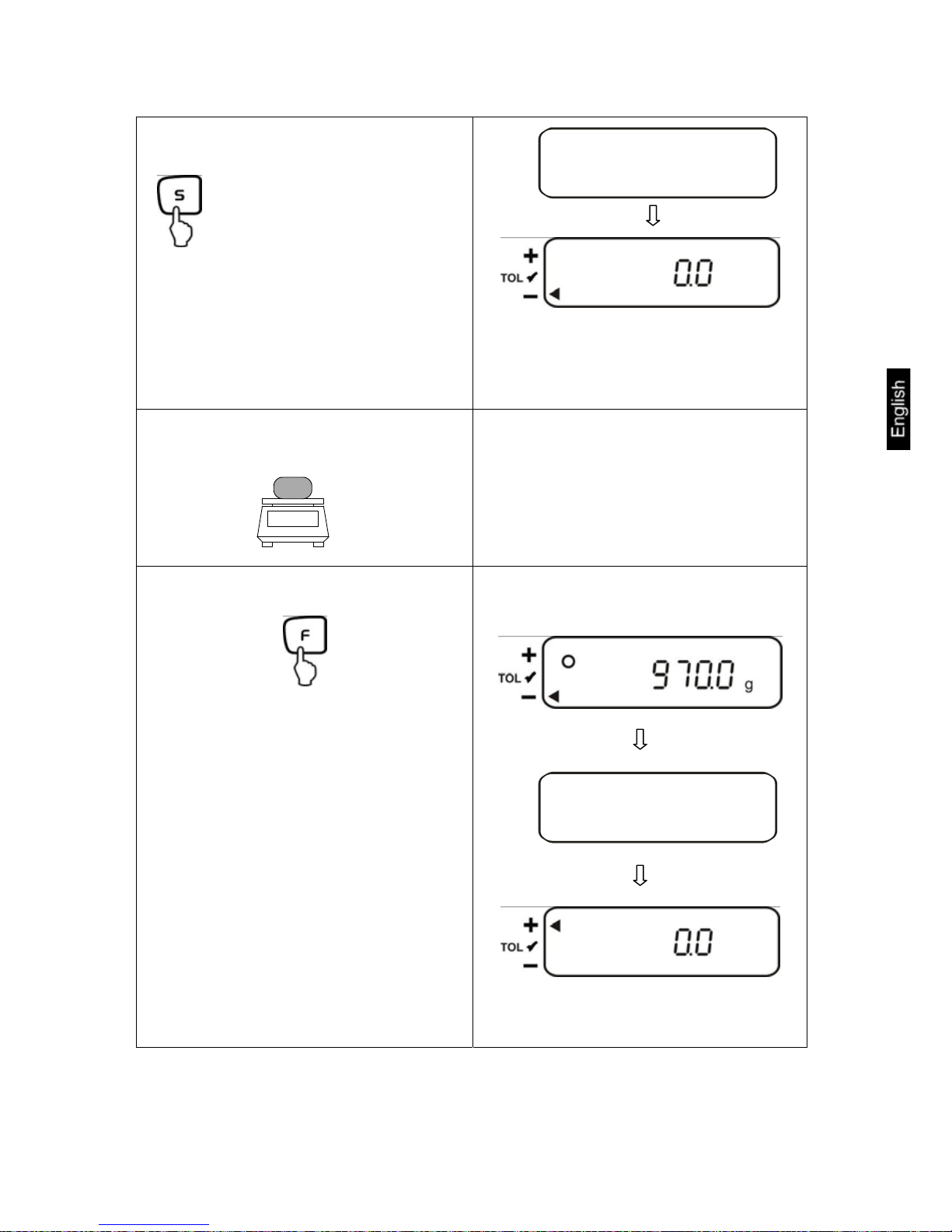
4. Entering a reference value:
Press for about 4 seconds, until
[R.SET] appears, then release.
R. SET
The flashing display (last saved value)
prompts you to enter a reference value
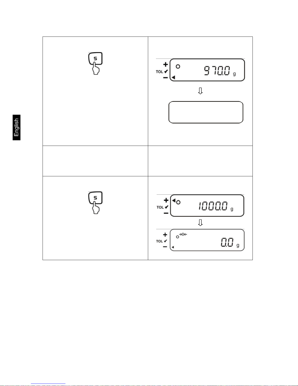
5. Place reference weight onto weighing
plate:
6. Save
An acoustic signal sounds, the saved
reference value is briefly displayed.*
L. SET
The flashing display (last saved value)
prompts you to enter the lower limiting
value
Page 69

FES/FEJ-BA-e-1132
69
7. Place sample for the first limiting
value on the weighing plate:
8. Save
An acoustic signal sounds, the saved
lower difference value is briefly displayed.
H. SET
K
The flashing display (last saved value)
prompts you to enter the upper limiting
value
9. Place sample for the upper (i.e. larger) limiting value on the weighing
plate:
10. Save
Remove sample from weighing plate.
The balance returns to tolerance weighing mode.
From here evaluation takes place
whether the goods to be weighed are
within the two tolerance limits.
An acoustic signal sounds, the saved
upper difference value is briefly displayed.
* If you want to set for your tolerance weighing only one limit point
(parameter selection [23. P1 .1]), the input herewith is finished.
Page 70

FES/FEJ-BA-e-1132
70
12.5.2 Entering 3 or 4 limits by weighing
To enter 3 or 4 limiting values [L1 SET] - [L3 SET] or [L4 SET], repeat steps 7 and
8 (see also chapter 12.4.2).
12.5.3 Numeric entering of 2 limits
Operation Display
1. Activate tolerance weighing function
[2.SEL.2] or [2.SEL.3] (see chap. 7).
rSEL2
2. Actuate required parameter selection
or
until
[23. P1 .2] or [24. TXP.2] appears;
more settings of your choice (see chap.
12.3) are carried out in the same way
2q CQ. 1
Parameter selection for 2 limiting points:
2s P . 2
1
Parameter selection for difference value:
2t TXP. 2
3. Leave function menu
a
z0
g
The balance is now in tolerance weighing mode; the tolerance marker ( ) appears
Page 71

FES/FEJ-BA-e-1132
71
4. Entering a reference value:
Press for about 4 seconds, until
[R.SET] appears, then release.
R. SET
The last saved reference weight appears
flashing
5.
Display changes to flashing "zero"
The flashing display prompts you to
numerically enter a reference weight
6. Entering a numeric value
or
⇒i⇒
0
1
⇒⇒⇒⇒≈
2
9
Any time you press TARE-key or the arrow key, you will go through the numbers
0-9, decimal dot and minus
Select the number to be changed (the
respective active position flashes)
or
Page 72

FES/FEJ-BA-e-1132
72
7. Confirm
An acoustic signal sounds, the saved
reference weight is briefly displayed.
L. SET
The flashing display (last saved value)
prompts you to enter the lower difference value
8. Entering lower limit
Repeat steps 5 and 6
9. Confirm
An acoustic signal sounds, the saved
lower difference value is briefly displayed.
H. SET
K
The flashing display (last saved value)
prompts you to enter the upper difference value
10. Entering upper limit
Repeat steps 5 and 6
Page 73

FES/FEJ-BA-e-1132
73
11. Save
The balance returns to tolerance weighing mode.
From here evaluation takes place
whether the goods to be weighed are
within the two tolerance limits.
An acoustic signal sounds, the saved
upper difference value is briefly displayed.
To enter 3 or 4 limiting values [L1 SET] - [L3 SET] or [L4 SET], repeat steps 8 and
9 (see also chapter 12.4.2).
13 Setting date and time
Display symbol [ L ]
13.1 Time
Operation Display
1. Call up menu
Keep pressed until
[D-SET] appears.
Fonm
D-SET
Page 74
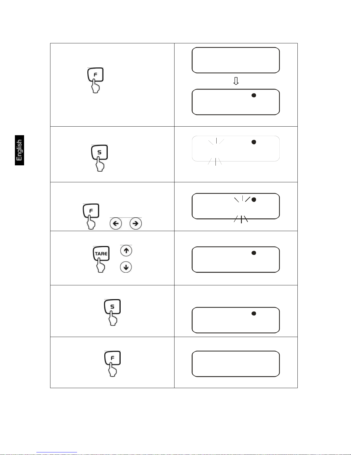
FES/FEJ-BA-e-1132
74
Press again
TKNE
15 OO OO
::
L
Last stored time appears.*
2. Resetting time
15 OO OO::
L
Time to be changed is flashing
Select the number to be changed (the
active position flashes):
or
15 OO OO::
L
Changing the numerical value
or
15 O O: 73:
L
3. Save
After storing your setting, the date
display will appear
1OO7-1 - 5
L
4. Return to weighing mode
a
z0
g
*Notice: The display can be rounded up (from 30 s) or down (to 29 s)
by pressing the TARE-key.
Page 75
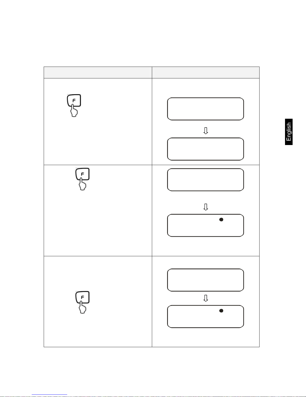
FES/FEJ-BA-e-1132
75
13.2 Date
You can set the display of your data output under menu item [ F. DATE]
(see menu overview chap. 7.2.).
Operation Display
1. Call up menu
Keep pressed until
[D-SET] appears.
Fonm
D-SET
Press again
TKNE
15 OO OO::
L
Last stored time appears
Press again
DATE
1OO7-1 - 5
L
Last stored date appears
Page 76

FES/FEJ-BA-e-1132
76
2. Resetting the date
1OO7-1 - 5
L
Time to be changed is flashing
Select the number to be changed (the
active position flashes):
or
1OO7-1 - 5
L
Changing the numerical value
or
1OO8-1 - 5
L
3. Save
After storing your settings, the balance
will automatically return to weighing
mode.
a
z0
g
Page 77
FES/FEJ-BA-e-1132
77
14 Description of individual functions
14.1 Auto sleep function
In this function the display of the balance is turned off after 3 minutes without load
change or operation to save energy.
Parameter selection: [ A. Au 1]
The Auto sleep function is indicated by a red LED.
NOTE:
This function is only available when connected to the mains power.
14.2 Auto OFF function
In this function the balance is turned off after 3 minutes without load change or operation to save the battery.
Parameter selection: [ 9. AP. 1]
The Auto OFF function is indicated by a green LED.
NOTE:
This function is only available for battery operation.
14.3 Set units function
With this setting you can set different display units (A or B) for one weighing value.
Press the -key to choose between units A and B.
14.4 Multiple range display
The models FES/FEJ62K0.1DIPM are by standard set as multiple range balance
6.2kg = 0.1g and 62kg= 1g readability. The balance can also be set as single range
balance with a readability of 1g.
Parameter selection: [ C. D.R 1]
Page 78
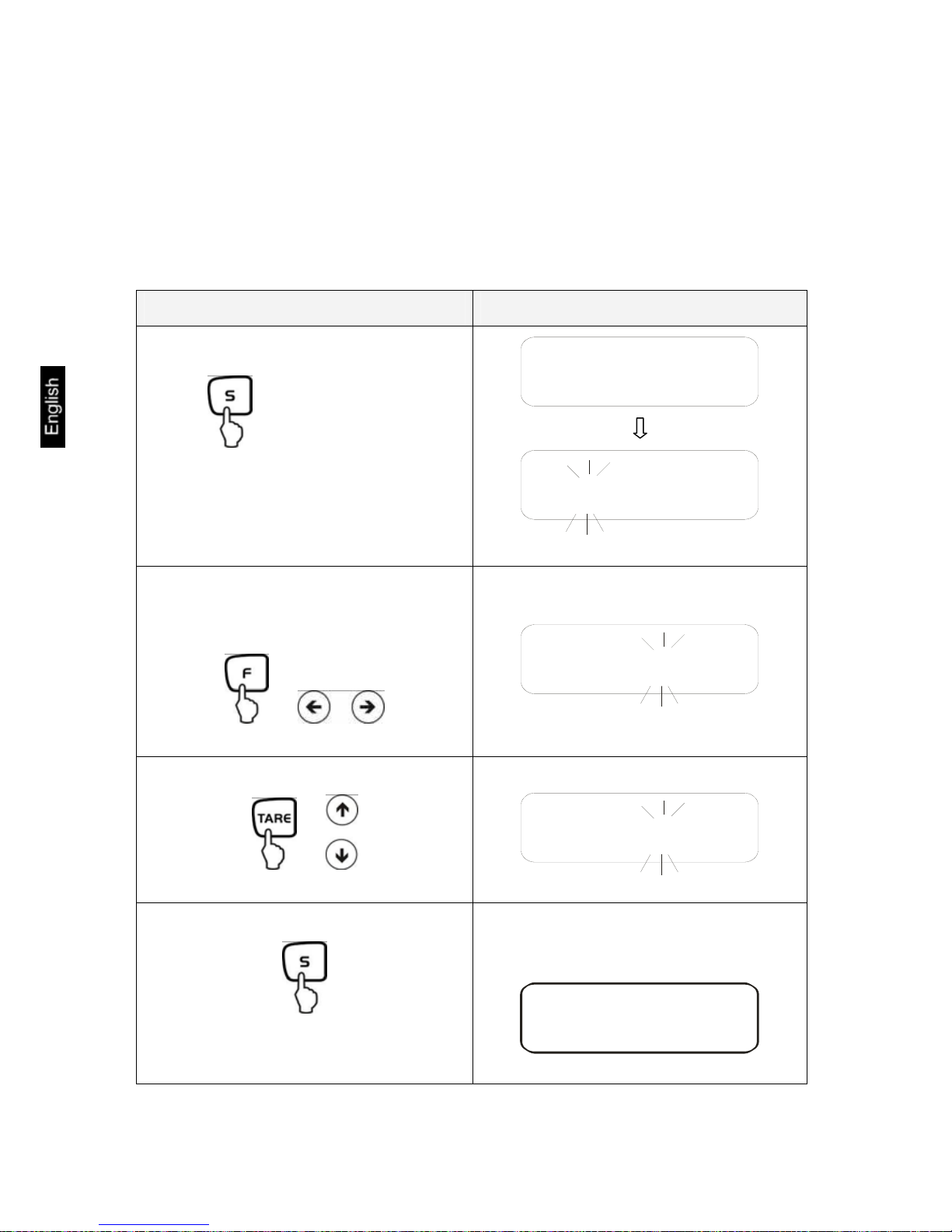
FES/FEJ-BA-e-1132
78
14.5 Interval output function
This menu item allows you to determine after which interval you wish data output to
be carried out. To achieve this, activate the [ 61. Q.m A ] or [ 61. Q.m B ] function
in the menu (see chpt. 7.2.1)
14.5.1 Interval setting
Operation Display
1. Call up menu
Keep pressed until
[KNT.UAL] appears.
KNT.UAL
00 1 0::OO
Time to be changed is flashing
2. Set interval
Select the number to be changed (the
active position flashes):
or
00 1 0::OO
Changing the numerical value
or
00 2 0::OO
3. Save:
After storing your settings, the balance
will automatically return to weighing
mode.
a
z0
g
Page 79
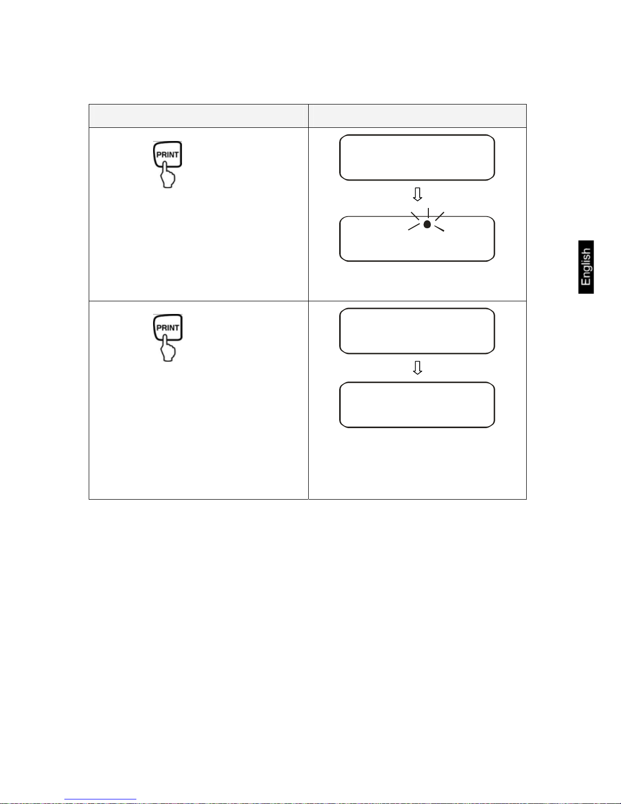
FES/FEJ-BA-e-1132
79
14.5.2 Start/Stop interval output
Operation Display
Start output
START
a
7z3
g
L
Stop output
END
a
z0
g
The balance returns automatically into
weighing mode.
Page 80

FES/FEJ-BA-e-1132
80
14.6 Input balance ID-no.
Display symbol [ W ] and [ S ]
You can enter a 6-digit number using the characters [0-9], [A-F] and [ - ]. Space
character is displayed as [ _ ].
Operation Display
1. Call up menu
+
Hold F-key while TARE –key is pressed
until [FWnm 2] is displayed.
see chapter 8.
Fonm2
When releasing, the first function is displayed [K. KD. O]
qKD0
2. Activate function
or
qKD1
3. Display serial number
000001
The last stored number appears
4. Input serial number
000001
Time to be changed is flashing
Page 81
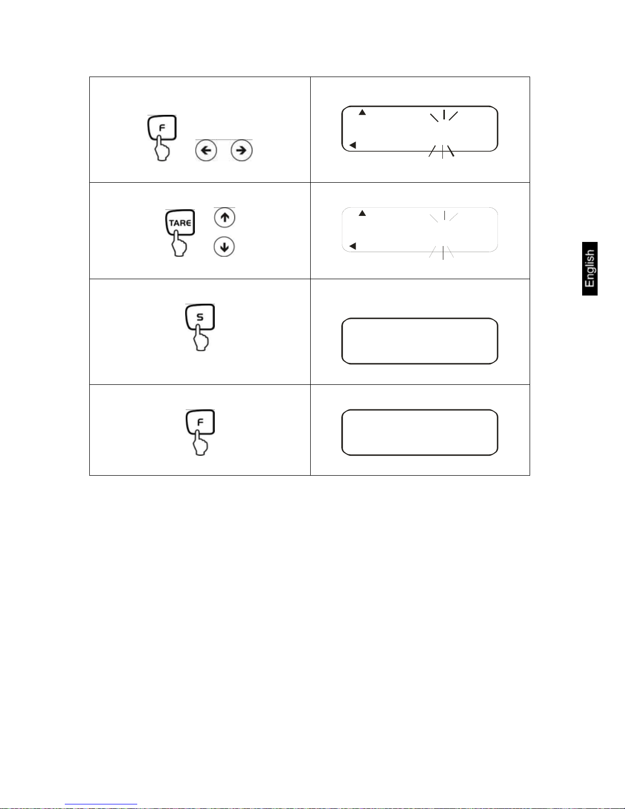
FES/FEJ-BA-e-1132
81
Select the number to be changed (the
active position flashes):
or
000001
Changing the numerical value
or
000501
5. Save:
Your setting will be stored and the next
menu item will appear.
2.CRCA. O
6. Return to weighing mode
a
z0
g
Page 82

FES/FEJ-BA-e-1132
82
15 Data output
The regular equipment of the balance includes an RS 232C interface and a printer
interface.
15.1 RS 232C interface
The RS 232C interface allows a bi-directional data exchange from the FEJ to external
devices. This data exchange is asynchronous using ASCII - Code.
Pin allocation of balance output plug:
Pin nr. Signal Input/Output Function
1 -
2 RXD Input Receive data
3 TXD Output Transmit data
4 DTR Output HIGH
5 GND - Signal ground
6 - -
7 - -
8 - -
9 - -
1
2
34
5
6789
Page 83

FES/FEJ-BA-e-1132
83
15.2 Printer interface (unidirectional data exchange)
Pin allocation of balance output plug:
Pin nr. Signal Input/Output Function
1 EXT.TARE Input External tare function
2 -
3 -
4 TXD Output Transmit data
5 GND - Signal ground
6 - -
7 - -
8 - -
15.3 Description of interface
The selection of a certain operating mode allows you to set the output format, the
output control, the transmission speed and the parity bit. The different options are
described in chap. 7.2.1 under "parameter for serial interface".
1
2
3
4
5
6
7
8
Page 84

FES/FEJ-BA-e-1132
84
15.4 Data output
15.4.1 Format for data transmission
Any of the data formats below may be set by selecting the relevant function on the
balance ( see menu overview chap. 7.2):
• 6-digit data format
Consisting of 14 words, including final character; CR=0DH, LF=0AH (CR=balance
reverse motion / LF=line feed)
1 2 3 4 5 6 7 8 9 10 11 12 13 14
P1 D1 D2 D3 D4 D5 D6 D7 U1 U2 S1 S2 CR LF
• 7-digit data format
1 2 3 4 5 6 7 8 9 10 11 12 13 14 15
P1 D1 D2 D3 D4 D5 D6 D7 D8 U1 U2 S1 S2 CR LF
NOTE: The 7-digit format is identical to the 6-digit, with the exception of the additional character D8.
• Extended 7-digit data format
Not documented
For models e (calibration) = 10 d (legibility) the formats shown below are available:
• 6-digit data format
1 2 3 4 5 6 7 8 9 10 11 12 13 14 15
P1 D1 D2 D3 D4 D5 D6 D7 D8 U1 U2 S1 S2 CR LF
Consisting of 15 words, including final character; CR=0DH, LF=0AH (CR=balance
reverse motion / LF=line feed). Slash "/" is inserted after the e-value.
• 7-digit data format
1 2 3 4 5 6 7 8 9 10 11 12 13 14 15 16
P1 D1 D2 D3 D4 D5 D6 D7 D8 D9 U1 U2 S1 S2 CR LF
Hinweis: The 7-digit format is identical to the 6-digit format with the exception of
the additional character D9.
Page 85

FES/FEJ-BA-e-1132
85
15.4.2 Signs
P 1 = 1 word
P1 Code Meaning
+ 2 B H Data is 0 or positive
- 2 D H Data is negative
15.4.3 Data
6-digit data format (D1-D7): 7 words
7-digit data format (D1-D8): 8 words
6-digit data format e = 10 d (D1-D7): 7 words
7-digit data format e = 10 d (D1-D8): 8 words
D1-D7, D8, D9 Code Meaning
0 - 9 30 H – 39 H Data 0 to 9 (max. 6 characters in 6-digit format)
2 EH Decimal point, position not fixed
Sp 20 H Space character, leading cero suppressed
/
2 FH Slash "/" is inserted after the e-value.
15.4.4 Units
U 1, U 2 = 2 words as ASCII-Codes
U1 U2 Code Meaning Symbol
(SP) G 20H 47H Gram g
K G 4BH 47H Kilogram kg
C T 43H 54H Karat
P C 50H 43H Quantity Pcs
(SP) % 50H 25H Percent %
Page 86

FES/FEJ-BA-e-1132
86
15.4.5 Result evaluation for balances with tolerance range
S 1 = 1 word
S1 Code Meaning
L 4CH Goods to be weighed below tolerance limit
G 47H Goods to be weighed within tolerance range
H 48H Goods to be weighed above tolerance limit
1- or 2 end
points
1 31H Limit 1
2 32H Limit 2
3 33H Limit 3
4 34H Limit 4
5 35H Limit 5
3- or 4 end
points
T 54H Value total
U 55H Weight value
(SP) 20H No rating
d 64H Gross
File type
15.4.6 Data status
S 2 = 1 word
S 2 Code Meaning
S 53 H Data stabilized *
U 55 H Data not stabilized (fluctuating) *
E 45 H Data error, all data apart from S 2 unreliable
Balance indicating error (o-Err, u-Err)
sp 20 H No special status
15.4.7 Interval data output
When an interval output is started or stopped, this will result in the output of a header
or footer line.
Header
consisting of 15 words
1 2 3 4 5 6 7 8 9 10 11 12 13 14 15
- - - - - - - - - - - - - - -
Footers
Two line feeds are inserted.
Page 87

FES/FEJ-BA-e-1132
87
15.4.8 Output time
1 2 3 4 5 6 7 8
h h : m m : s s
* hh: Hours (00-23), mm: Minutes (00-59) min: Seconds (00-59) s:
15.5 Remote control instructions
C1 C2 Code Meaning
0 0 4FH 30H No data output
0 1 4FH 31H Continuous data output
0 2 4FH 32H Continuous data output stable weighing values
0 3 4FH 33H
Output for stable and instable weighing values after
pressing PRINT key
0 4 4FH 34H
Output for stable weighing value after previous relief of balance
0 5 4FH 35H
One output for stable weighing value. No output for
stable weighing values. Renewed output after stabilization
0 6 4FH 36H
One output for stable weighing value. Continuous
output for instable weighing values.
0 7 4FH 37H
Output of stable weighing values after pressing
PRINT key
0 8 4FH 38H Single immediate output
0 9 4FH 39H Single output after stabilization
0 A 4FH 41H
Single, immediate output after fixed interval (see
chap. 14.5)
0 B 4FH 42H
Single, immediate output after fixed interval and stable weighing value (see chap 14.5)
Page 88

FES/FEJ-BA-e-1132
88
16 Service, maintenance, disposal
16.1 Cleaning
Before cleaning, please disconnect the appliance from the operating voltage.
Please do not use aggressive cleaning agents (solvents or similar agents), but a cloth
dampened with mild soap suds.
The weighing terminal has a pressure compensation device.
This is underneath the terminal and made of a glued on membrane.
When cleaning please ensure that the membrane is not damaged or soiled.
16.2 Service, maintenance
The appliance may only be opened by trained service technicians who are
authorized by KERN.
Before opening, disconnect from power supply.
16.3 Disposal
Disposal of packaging and appliance must be carried out by operator according to
valid national or regional law of the location where the appliance is used.
Page 89

FES/FEJ-BA-e-1132
89
17 Instant help
In case of an error in the program process, briefly turn off the balance and disconnect
from power supply. The weighing process must then be restarted from the beginning.
Help:
Fault Possible cause
The displayed weight does not glow.
• The balance is not switched on.
• The mains supply connection has been
interrupted (mains cable not plugged
in/faulty).
• Power supply interrupted.
The displayed weight is permanently
changing
• Draught/air movement
• Table/floor vibrations
• The weighing plate is in contact with for-
eign matter.
• Electromagnetic fields / static charging
(choose different location/switch off interfering device if possible)
The weighing value is obviously
• The display of the balance is not at zero
wrong
• Adjustment is no longer correct.
• Great fluctuations in temperature.
• Electromagnetic fields / static charging
(choose different location/switch off interfering device if possible)
Should other error messages occur, switch balance off and then on again. If the error
message remains inform manufacturer.
 Loading...