

Page 1
QUICK START GUIDE
KEPCO
An ISO 9001 Company.
KLP
KLP POWER SUPPLY
This guide gives a brief introduction to the KLP Power supply, shows simple load connections, and
allows you to verify the power supply is working. The guide also shows you how to use the front panel
controls to perform the most commonly used functions.
Accessing Manuals. First determine your Firmware Version (see below), then download the KLP User
Manual and Developer’s Guide from www.kepcopower.com/support/opmanls.htm#klp. Refer to the KLP
User Manual for full specifications, installation considerations and operating instructions. An Installation/
Operation Summary includes hyperlinked references to detailed procedure, but which can be printed as
a handy reference. Refer to the KLP Developer’s Guide for a full description of the digital interfaces, their
associated drivers, and the SCPI command language.
Firmware Version. Refer to www.kepcopower.com/utility/util.htm to determine which firmware version is
installed. The KLP can be upgraded to the latest version at no cost using the Kepco Upgrade Utility, also
available at www.kepcopower.com/utility/util.htm.
Accessing Drivers. Drivers are accessed from www.kepcopower.com/drivers/drivers-dl3.htm.
CONTENTS
DESCRIPTION. . . . . . . . . . . . . . . . . . . . . . . . . . . . . . . . . . . . . . . . . . . . . . . . . . . . . . . . . . . . . . . . . . . . .2
UNPACKING. . . . . . . . . . . . . . . . . . . . . . . . . . . . . . . . . . . . . . . . . . . . . . . . . . . . . . . . . . . . . . . . . . . . . . . 2
EQUIPMENT SUPPLIED. . . . . . . . . . . . . . . . . . . . . . . . . . . . . . . . . . . . . . . . . . . . . . . . . . . . . . . . . . . . .2
ACCESSORIES. . . . . . . . . . . . . . . . . . . . . . . . . . . . . . . . . . . . . . . . . . . . . . . . . . . . . . . . . . . . . . . . . . . .3
SAFETY. . . . . . . . . . . . . . . . . . . . . . . . . . . . . . . . . . . . . . . . . . . . . . . . . . . . . . . . . . . . . . . . . . . . . . . . . .3
PRELIMINARY OPERATIONAL CHECK. . . . . . . . . . . . . . . . . . . . . . . . . . . . . . . . . . . . . . . . . . . . . . . . . 4
INSTALLATION. . . . . . . . . . . . . . . . . . . . . . . . . . . . . . . . . . . . . . . . . . . . . . . . . . . . . . . . . . . . . . . . . . . .5
Input Connections. . . . . . . . . . . . . . . . . . . . . . . . . . . . . . . . . . . . . . . . . . . . . . . . . . . . . . . . . . . . . . . 5
Load Connections. . . . . . . . . . . . . . . . . . . . . . . . . . . . . . . . . . . . . . . . . . . . . . . . . . . . . . . . . . . . . . . 5
Local Sensing (Factory Default). . . . . . . . . . . . . . . . . . . . . . . . . . . . . . . . . . . . . . . . . . . . . . . . . . . . . 6
Remote Sensing Select. . . . . . . . . . . . . . . . . . . . . . . . . . . . . . . . . . . . . . . . . . . . . . . . . . . . . . . . . . . 6
Analog I/O Connections. . . . . . . . . . . . . . . . . . . . . . . . . . . . . . . . . . . . . . . . . . . . . . . . . . . . . . . . . . .7
GPIB Connections. . . . . . . . . . . . . . . . . . . . . . . . . . . . . . . . . . . . . . . . . . . . . . . . . . . . . . . . . . . . . . . 7
RS 232 Connections (Standard Models). . . . . . . . . . . . . . . . . . . . . . . . . . . . . . . . . . . . . . . . . . . . . .7
LAN Connections (E-Series Models). . . . . . . . . . . . . . . . . . . . . . . . . . . . . . . . . . . . . . . . . . . . . . . . .7
OPERATION. . . . . . . . . . . . . . . . . . . . . . . . . . . . . . . . . . . . . . . . . . . . . . . . . . . . . . . . . . . . . . . . . . . . . . .7
Turning the Power Supply On. . . . . . . . . . . . . . . . . . . . . . . . . . . . . . . . . . . . . . . . . . . . . . . . . . . . . .7
Enabling/disabling Output Power. . . . . . . . . . . . . . . . . . . . . . . . . . . . . . . . . . . . . . . . . . . . . . . . . . . . 8
Checking or changing Voltage/Current Setpoints. . . . . . . . . . . . . . . . . . . . . . . . . . . . . . . . . . . . . . . 8
Virtual Model Setting. . . . . . . . . . . . . . . . . . . . . . . . . . . . . . . . . . . . . . . . . . . . . . . . . . . . . . . . . . . . .8
Setting voltage or current. . . . . . . . . . . . . . . . . . . . . . . . . . . . . . . . . . . . . . . . . . . . . . . . . . . . . . . . . . 9
Last Setting Recall. . . . . . . . . . . . . . . . . . . . . . . . . . . . . . . . . . . . . . . . . . . . . . . . . . . . . . . . . . . . . .10
Viewing/Changing Overvoltage or Overcurrent Protection Values. . . . . . . . . . . . . . . . . . . . . . . . . 10
KLP OUTLINE DIMENSIONS . . . . . . . . . . . . . . . . . . . . . . . . . . . . . . . . . . . . . . . . . . . . . . . . . . . . . . . . 11
KEPCO, INC. 131-38 SANFORD AVENUE FLUSHING, NY. 11355 U.S.A. TEL (718) 461-7000 FAX (718) 767-1102
©2012, KEPCO, INC
Data subject to change without notice
http://www.kepcopower.com email: hq@kepcopower.com
228-1616 REV 6 070312
Page 2
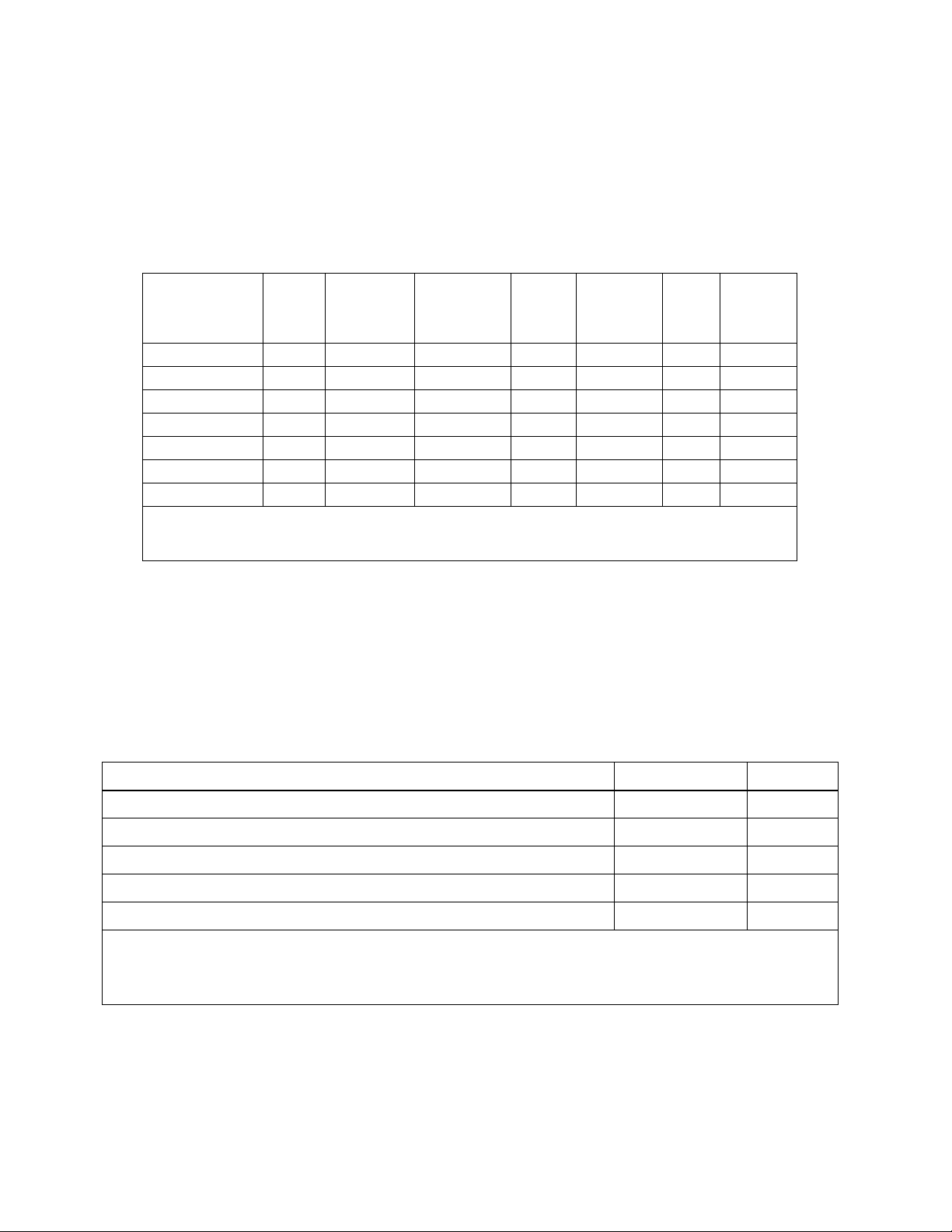
DESCRIPTION. The KLP Power Supply Series are universal input, automatic crossover, 1200-watt
constant power, voltage/current stabilizers with a full rectangular output characteristic. There are seven
standard models (also referred to as -1200) and seven E -Series models (formerly referred to as -1.2K)
(see Table 1). The standard models are GPIB and RS 232 compatible; the E-Series models are GPIB
and LAN compatible; all models allow remote analog programming. For each model a multitude of virtual
models can be configured. The “rated voltage, maximum current at rated voltage” and “rated current and
maximum voltage at rated current” parameters define the virtual models available within the limit of 1200
Watts of output power.
TABLE 1. MODEL PARAMETERS
Model number
KLP 10-150
KLP 20-120
KLP 36-60
KLP 75-33
KLP 150-16
KLP 300-8
KLP 600-4
(1) The maximum current and voltage are constrained by the 1200 watt power limitation.
(2) Bandwidth: 20MHz; low frequency ripple may be higher at loads less than 30 Watts.
(3) Specifications listed apply to both standard (-1200) and E-Series (suffix E) models.
(3)
(3)
(3)
(3)
(3)
(3)
(3)
Rated
Vol tag e
Range
0-10V 120A@10V 1.9A 0-150A 8V@150A 60 mV 80%
0-20V 60A@20V 1.5A 0-120A 10V@120A 60 mV 82%
0-36V 33.3A@36V 0.8A 0-60A 20V@60A 60 mV 83%
0-75V 16A@75V 0.4A 0-33.3A 36V@33.3A 60 mV 84%
0-150V 8A@150V 0.2A 0-16A 75V@16A 125 mV 86%
0-300V 4A@300V 0.1A 0-8A 150V@8A 150 mV 87%
0-600V 2A@600V 0.05A 0-4A 300V@4A 150 mV 88%
Maximum
current for
(1)
rated voltage
Minimum
programmable
current
Rated
Current
Range
Maximum
voltage for
(1)
rated current
Ripple
and
noise
(2)
p-p
Efficiency
@115 Va-c
UNPACKING. This instrument has been thoroughly inspected and tested prior to packing and is
ready for operation. After careful unpacking, inspect for shipping damage before attempting to operate.
Perform the PRELIMINARY OPERATIONAL CHECK. If any indication of damage is found, file an immediate claim with the responsible transport service.
EQUIPMENT SUPPLIED. See Table 2.
TABLE 2. EQUIPMENT SUPPLIED
ITEM
Source power connector 142-0381 1
Jumper (24 AWG or larger bus wire) for local sensing connections 172-0585 2
Analog I/O port mating connector 142-0528 1
Nut, 1/4-20, with captive lockwasher (on output studs of 10V, 20V and 36V models only) 102-0175 2
Quick Start Guide * 228-1616 1
* User Manual and Developer’s Guide are available as free downloads from:
www.kepcopower.com/support/opmanls.htm#klp
Drivers are available as free downloads from
www.kepcopower.com/drivers/drivers-dl3.htm#klp
PART NUMBER QUANTITY
KEPCO, INC. 131-38 SANFORD AVENUE FLUSHING, NY. 11355 U.S.A. TEL (718) 461-7000 FAX (718) 767-1102
http://www.kepcopower.com email: hq@kepcopower.com
2 228-1616 REV 6 070312
Page 3
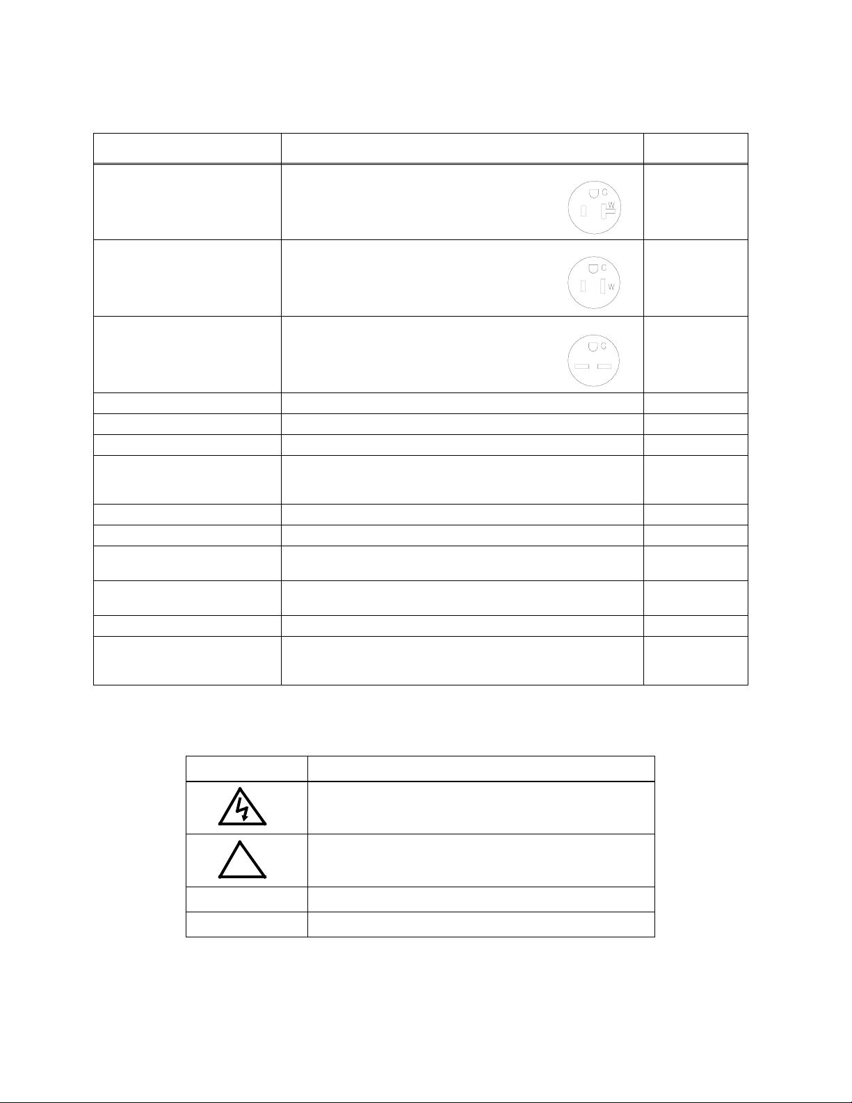
ACCESSORIES. See Table 3.
TABLE 3. ACCESSORIES
ITEM FUNCTION
Line Cord Set (125V/20A) 2.5m long cord set, provides for source power
connection. Mates with NEMA 5-20R receptacle
(see adjacent figure). Supports rated load power
over mains voltage range of 90-136V a-c.
Line Cord Set (125V/15A) 2.5m long cord set, provides for source power
connection. Mates with NEMA 5-15R receptacle
(see adjacent figure). Supports restricted load
power over mains voltage range of 90-136V a-c
(contact Kepco Sales Engineering for details).
Line Cord Set (250V/15A) 2.5m long cord set, provides for source power
connection. Mates with NEMA 6-15R receptacle
(see adjacent figure). Supports rated load power
over mains voltage range of 180-265V a-c.
IEEE 488 (GPIB) Cable, 1m long Connect KLP Power Supply to GPIB bus. SNC 488-1
IEEE 488 (GPIB) Cable, 2m long Connect KLP Power Supply to GPIB bus. SNC 488-2
IEEE 488 (GPIB) Cable, 4m long Connect KLP Power Supply to GPIB bus. SNC 488-4
Chassis Slide Allows rack-mounted units to slide in and out. Two (2) slides required
per power supply.
Analog Connector Backshell Locks analog port mating connector to KLP via jackscrews. 108-0204
Loop Back Test Connector Used for verification of RS 232 operation. 195-0112
Null Modem Cable, 10 ft. Connect RS 232 port with controlling computer, DB9F to DB9F, 10 feet
long.
Null Modem Cable, 1 ft. Used for Master/Slave connections. Connects RS 232 ports of stacked
power supplies, DB9F to DB9F, one foot long.
LAN Patch cable Connects KLP LAN port to LAN, 10 ft long. 118-1115
Support bracket, rear Provides extra support to rear of rack-mounted unit if needed. Two
brackets required per unit. Each bracket requires 2 screws and 2
washers. See Figure 4, sheet 1, Detail “A” for requirements.
NEMA 5-20R 118-0776
NEMA 5-15R 118-1136
NEMA 6-15R 118-1137
KEPCO
PART NUMBER
108-0239
(Jonathan
375-QD Series)
118-1176
118-1220
128-2306
SAFETY. See Table 4
TABLE 4. SAFETY SYMBOLS
SYMBOL MEANING
CAUTION: RISK OF ELECTRIC SHOCK.
CAUTION: REFER TO REFERENCED PROCEDURE.
!
WARNING INDICATES THE POSSIBILITY OF BODILY INJURY OR DEATH.
CAUTION INDICATES THE POSSIBILITY OF EQUIPMENT DAMAGE.
KEPCO, INC. 131-38 SANFORD AVENUE FLUSHING, NY. 11355 U.S.A. TEL (718) 461-7000 FAX (718) 767-1102
070312 228-1616 REV 6 3
http://www.kepcopower.com email: hq@kepcopower.com
Page 4

PRELIMINARY OPERATIONAL CHECK. A simple operational check after unpacking and
before equipment installation is advisable to ascertain whether the power supply has suffered damage
resulting from shipping.
NOTE: This test must be performed with all I/O ports disconnected, and ANALOG I/O SETTINGS
switch positions 3, 4 and 5 set to OFF (up).
1 With POWER circuit breaker set to OFF position, connect the power supply to source power (see
See “Input Connections.” on page 5.).
2 With no load connected, set POWER circuit breaker to the ON position. Each time the unit is turned
on an internal self-test is performed (see “Turning The Power Supply On.” on page 7). After the test
has been successfully completed, the status display reads SET (setpoint mode), the DC VOLTS display reads 0 Volts and the DC AMPERES display reads minimum Amperes (see Note 1, below).
NOTES: 1. A minimum programmed current (actual value depends on model) is required to ensure proper
operation of the power supply under all load conditions. Programmed current is automatically set
to be at least the minimum current.
2. If an error indication is blinking in the Status display, refer to User Manual for an explanation of
error codes.
3 Rotate VOLTAGE adjust knob clockwise. Verify that DC VOLTS display increases in large (X 100)
increments.
4 Press and rotate VOLTAGE adjust knob clockwise. Verify the DC VOLTS display increases in finer
increments than step 3, then release knob.
5 Adjust VOLTAGE adjust knob clockwise until Status display reads >MAX. Tap either VOLTAGE or
CURRENT adjust knob once to enter values. Verify Status display is blank
6 Connect a digital voltmeter (DVM) to the (M+) and (M–) terminals on the rear panel.
7 Press and release DC OUTPUT switch to enable the output. Verify DC OUTPUT indicator lights.
8 Compare the programmed output voltage value (step 5) with the voltage reading of the DVM; the dif-
ference between the two should not exceed 0.05% of the maximum voltage of the unit.
9 Compare the voltage reading of the DC VOLTS display with that of the DVM; the difference between
the two should not exceed 0.1% of the maximum voltage of the unit.
10 Enter different value for output voltage, then repeat steps 4 and 5 using different values for pro-
grammed voltage.
11 Disable the output by pressing and releasing DC OUTPUT switch; verify front panel DC VOLTS and
DC AMPERES displays read 0.0V and minimal current and the DC OUTPUT indicator is off.
12 Set POWER ON/OFF circuit breaker to OFF and disconnect from source power, load and test equip-
ment.
KEPCO, INC. 131-38 SANFORD AVENUE FLUSHING, NY. 11355 U.S.A. TEL (718) 461-7000 FAX (718) 767-1102
4 228-1616 REV 6 070312
http://www.kepcopower.com email: hq@kepcopower.com
Page 5

INSTALLATION. Install units in a 19 inch-wide rack. Optional slides may be used. Leave the front
and rear panels clear of obstructions to ensure adequate cooling. For parallel, series and master-slave
configurations, refer to the User Manual.
INPUT CONNECTIONS. Wire the mating source power connector provided (142-0381) for your input
mains (see Table 5 for mains voltage range). The user must provide a properly sized and rated mains
lead (line cord) and service with a current rating compatible with the anticipated input current. Line cords
available as accessories are listed in Table 3. Plug the source power connector into the source power
inlet connector at the rear panel.
TABLE 5. INPUT CURRENT SERVICE RATING AND CONDUCTOR SIZES
MAINS VOLTAGE RANGE CURRENT SERVICE RATING CONDUCTOR SIZE
100 - 132V a-c, 50/60Hz 20 Amp #12AWG [2,0 mm²]
180 - 265V a-c, 50/60Hz 15 Amp #14AWG [1,6 mm²]
LOAD CONNECTIONS. Connect the load to the (+) and (–) DC OUTPUT terminals on the rear panel
(Figure 2). (+M) and (–M) outputs are for connection of external monitoring equipment such as a DVM,
oscilloscope, etc.
Configuration of local sensing is facilitated by pre-installed jumpers which configure the unit for local
sensing.as shown in Figure 2.
NOTE: Output Sense lines must be connected for proper operation, either locally, or at the load
(remote).
FIGURE 1. KLP SERIES, FRONT PANEL CONTROLS AND INDICATORS
KEPCO, INC. 131-38 SANFORD AVENUE FLUSHING, NY. 11355 U.S.A. TEL (718) 461-7000 FAX (718) 767-1102
070312 228-1616 REV 6 5
http://www.kepcopower.com email: hq@kepcopower.com
Page 6

LOCAL SENSING (FACTORY DEFAULT). Unit is shipped with local sensing jumpers installed: +S
connected to +M and –M connected to –S (see Figure 2).
FIGURE 2. KLP SERIES, REAR PANEL VIEW, JUMPERS INSTALLED FOR LOCAL SENSING
REMOTE SENSING SELECT. First remove the factory-installed local sensing jumpers between +S
and +M and between –M and –S. Then connect the +S and –S lines at the load, observing proper polarity (see Figure 3). A high frequency bypass network consisting of two capacitors connected across the
error sensing point as shown in Figure 3 is recommended to reduce noise in the sense loop.
FIGURE 3. REMOTE SENSING
KEPCO, INC. 131-38 SANFORD AVENUE FLUSHING, NY. 11355 U.S.A. TEL (718) 461-7000 FAX (718) 767-1102
6 228-1616 REV 6 070312
http://www.kepcopower.com email: hq@kepcopower.com
Page 7

ANALOG I/O CONNECTIONS. The Analog I/O Port connector, located on the rear panel of the KLP
power supply (see Figure 2), provides access to analog programming inputs, status signal outputs and
an external trigger input available for use with SCPI *TRG and TRIG commands.
GPIB CONNECTIONS. Your computer must have a GPIB interface card installed. Connect the power
supply to the computer’s GPIB interface card. Use a standard GPIB interface cable at the GPIB port on
the rear panel (see Figure 2). The default GPIB address is 6. Refer to the User manual to change it from
the front panel, or to the Developer’s Guide to change it using SCPI commands.
RS 232 CONNECTIONS (STANDARD MODELS). Connect the KLP to a modem using a Null Modem
patch cable at the RS 232 port located on the rear panel (See Figure 2). A Null Modem cable is not
required for older MAC computers with D-sub serial port in which the RXD and TXD line transposition is
accomplished via external hardware. The default baud rate is 38400. Refer to the User manual to
change it from the front panel, or to the Developer’s Guide to change it using SCPI commands.
LAN CONNECTIONS (E-SERIES MODELS). The LAN interface allows the KLP to communicate via a
built-in web port (using web pages from a standard browser), as well as through other built-in LAN ports.
Connect the KLP to the LAN via the RJ 45 LAN port located at the rear panel (See Figure 2). Refer to the
User manual to configure the LAN interface from the front panel or through the web interface. Refer to
the Developer’s Guide for the associated SCPI commands
OPERATION. Additional features covered in the User Manual are: Quick Boot (eliminating the power-
up displays), use of the internal relay, operation via the LAN interface or analog signals and setting
coarse/fine adjustment preference of the VOLTAGE and CURRENT controls. An Installation/Operation
Summary is also included in the User manual. The Developer’s Guide covers the GPIB and RS 232 and
LAN interfaces, including the use of the drivers downloadable from:
www.kepcopower.com/drivers/drivers-dl3.htm#klp.
TURNING THE POWER SUPPLY ON. To turn the power supply on, set POWER ON/OFF circuit
breaker (Figure 1) to ON. If an error occurs, an error code is displayed in the status display (see User
Manual.)
1 When the power supply is turned on, it performs a self-test and displays the following information:
• Status display flashes KLP for 2 seconds while DC VOLTS and DC AMPERES displays show the max-
imum voltage and current capability of the unit.
• Status display flashes LXI for 2 seconds if unit is an E-Series model
• Status display flashes
installed.
• Status display flashes
maximum voltage and current allowed for a previously programmed virtual model.
• Status display flashes PROT for 2 seconds while DC VOLTS and DC AMPERES displays show previ-
ously stored OVP and OCP trigger levels.00
RODC for 2 seconds if unit has the Rapid Output Discharge Circuit option
VIRT for 2 seconds while DC VOLTS and DC AMPERES displays show the
2 After a successful self test, the default conditions upon power up are as follows:
• Status display shows SET,
• Output is disabled (green DC OUTPUT indicator is off).
• DC VOLTS and DC AMPERES displays show programmed output conditions: 0 Volts, minimum
Amperes (if DIP switch position 3 was ON when the unit was turned off, previously saved setpoint values are displayed).
NOTE: A minimum programmed current is required to ensure proper operation of the power supply under all
load conditions. Programmed current is automatically set to be at least the minimum current (actual
value depends on model, see Table 1).
• Since the output is off, Constant Voltage (CV) mode indicator (green LED) and Constant Current (CC)
indicator (amber LED) are off.
KEPCO, INC. 131-38 SANFORD AVENUE FLUSHING, NY. 11355 U.S.A. TEL (718) 461-7000 FAX (718) 767-1102
070312 228-1616 REV 6 7
http://www.kepcopower.com email: hq@kepcopower.com
Page 8

ENABLING/DISABLING OUTPUT POWER. When the power supply is turned on, the output is auto-
matically disabled (DC OUTPUT LED is off), the DC VOLTS and DC AMPERES displays show the programmed output voltage and current set points and “SET” appears in the status display.
1 To enable the output, first exit SET mode by tapping either the VOLTAGE or CURRENT control, then
press and release the DC OUTPUT switch. The associated green LED lights to indicate output
power is applied to the load. Each time you exit SET mode, the setpoint values are stored for possible recall if the power supply is turned off or the output is disabled.
2 To disable the output, press and release the DC OUTPUT switch again. The DC OUTPUT indicator
goes off.
NOTE: While in the setpoint mode (Status display reads SET) the output cannot be turned on
(pressing DC OUTPUT has no effect). If output was on while setpoint mode was entered,
pressing DC OUTPUT will disable the output.
CHECKING OR CHANGING VOLTAGE/CURRENT SETPOINTS.
CAUTION: When the output is disabled, the DC VOLTS and DC AMPERES displays show the
actual output voltage and current. Before enabling the output ALWAYS check the setpoints to avoid possible damage to the load.
1 Tap either the VOLTAGE or CURRENT control. The status display reads SET, and the DC VOLTS
and DC AMPERES displays show the stored setpoints.
2 To accept the displayed value, tap the associated adjustment control again. To change the value,
rotate the control (press the control in while rotating for fine adjustment; or see User Manual to set
coarse/fine preference), then tap the adjustment control again to accept the new setting.
NOTE: Before changing the setpoint, note the displayed setpoint. If you decide not to change the
value after rotating the control, you must rotate the control to the value noted, then tap the
adjustment control to accept.
VIRTUAL MODEL SETTING. The virtual model establishes a maximum programmable voltage and
current for the unit within the 1200W power limitation and the maximum voltage and current ratings listed
in Table 1. The unit will not accept programmed values beyond these values.
1 Using a thin tool (e.g., a paper clip), press the FUNCTION switch once so that the status display
reads VIRT. The DC VOLTS and DC AMPERES displays show the programmed maximum voltage
and current of the virtual model.
2 To exit, rotate either VOLTAGE or CURRENT control until Status display reads EXIT, then tap DC
OUTPUT switch. To change the virtual model limits refer to the User Manual.
KEPCO, INC. 131-38 SANFORD AVENUE FLUSHING, NY. 11355 U.S.A. TEL (718) 461-7000 FAX (718) 767-1102
8 228-1616 REV 6 070312
http://www.kepcopower.com email: hq@kepcopower.com
Page 9

SETTING VOLTAGE OR CURRENT. The VOLTAGE and CURRENT controls adjust output voltage
and current limit, respectively, when the unit is in constant voltage (CV) mode and adjust voltage limit
and output current, respectively, when the unit is in constant current (CC) mode. The mode (CV or CC) is
determined by the load together with the programmed settings. As long as the voltage across the load
produces a current that is less than the programmed Current setpoint, the unit operates in CV mode
(voltage programmed to voltage setpoint, current limited by current setpoint). If the load changes to the
point that current through the load reaches the current setpoint, the unit automatically enters CC mode
(current programmed to current setpoint, voltage limited by voltage setpoint).
Output voltage or current can be set at the front panel in two ways: Real-time adjustment or Setpoint
adjustment.
Real-time Voltage/Current Adjustment. Rotating the associated control will change the output voltage or current in real-time only if the output is enabled. If the unit is in constant voltage mode (CV indicator lit) the DC VOLTS display shows the actual output voltage as the VOLTAGE control is rotated. Similarly, if the unit is in constant current mode (CC indicator lit) the DC AMPERES display shows the actual output current as the CURRENT control is rotated.
• If the unit is in CV mode, rotating the CURRENT control will affect the current limit even though the DC
AMPERES display does not change since it is showing actual output current. Similarly, rotating the
VOLTAGE control while in CC mode affects the voltage limit. To change the limits to a precise value,
refer to SETPOINT ADJUSTMENT.
• Voltage and current settings are not allowed to exceed either a) the virtual model setting or b) 80% of
the protection value. Attempts to set voltage or current beyond these limits will not be accepted. The
status display shows either >MAX for virtual model, >OVP for voltage protection, or >OCP for current
protection to indicate which limit is being exceeded.
Setpoint Voltage/Current Adjustment.
1 Tap either the VOLTAGE or CURRENT control to initiate setpoint adjustment (status display reads
SET). The previous setpoint is visible on the corresponding DC VOLTS or DC AMPERES display.
2 Rotate the corresponding control to change the setpoint as viewed on the corresponding LED dis-
play. Tap the adjustment control again to accept the new setting.
• In the setpoint mode, both coarse (rotate the control) and fine (rotate while pressing control in) adjustment is available. The coarse adjustment is approximately 100X the fine adjustment resolution.
• Setpoint adjust can be done with output either on or off, however the output can not be enabled while
setpoint is active.
• Voltage and current settings are not allowed to exceed either a) the virtual model setting or b) 80% of
the protection value. Attempts to set voltage or current beyond these limits will not be accepted. The
status display shows either >MAX for virtual model, >OVP for voltage protection, or >OCP for current
protection to indicate which limit is being exceeded.
• If you decide not to change the value after rotating the control, the previous setpoint value will be
restored after about 20 seconds of inactivity. Then tap either adjustment control to accept.
KEPCO, INC. 131-38 SANFORD AVENUE FLUSHING, NY. 11355 U.S.A. TEL (718) 461-7000 FAX (718) 767-1102
070312 228-1616 REV 6 9
http://www.kepcopower.com email: hq@kepcopower.com
Page 10

LAST SETTING RECALL. KLP is capable of saving the last setpoint values for voltage and current
prior to unit shutdown, and recalling them when the unit is next turned on. Enable this function prior to
power-up by setting Analog I/O Switch 3 to the ON (down) position (see Figure 2). Upon next power-up,
each setpoint entry for voltage and current is stored in non-volatile memory, with latest settings displacing prior ones. When the power supply is turned off, the last settings are saved and automatically
retrieved at next power-up as the starting setpoints.
• Recall is for SETPOINT ADJUSTMENTS only; output changes entered as REALTIME ADJUSTMENTS
are not saved.
• To disable this function, turn the unit off and set Analog I/O Switch 3 to the OFF (up) position. At next
power-up, the stored value buffer is cleared and setpoints will default to zero volts and minimum current.
• If the virtual model for the power supply is altered, the last settings are reset to zero volts and minimum
current.
VIEWING/CHANGING OVERVOLTAGE OR OVERCURRENT PROTECTION VALUES.
Overvoltage and Overcurrent protection values can be individually programmed. The range for overvoltage and overcurrent values are 0.2 to 1.2 x E
max and 0.72 to 1.2 x IOmax.
O
If the output voltage/current exceeds the overvoltage/overcurrent protection value, the protection circuit
latches the output off, flashes an overvoltage (OVP) or overcurrent (OCP) protection error message on
the status display and sets a status bit that can be retrieved through the RS 232, GPIB or LAN port. The
unit must be cycled on and off to restore the output.
• The maximum values are 1.2 x EOmax for overvoltage protection, and 1.2 x IOmax for overcurrent protection.
• A built-in feature prevents the unit from being programmed within 20% of OVP or 20% of OVC (or the
minimum OVC which is 72% of I
tively, programming of the output is automatically limited to 10V and 60A.
• When a virtual model is defined, OVP and OVC are automatically set 20% and 20%, respectively,
above the maximum programmable values established by the virtual model. If OVP or OVC are lowered by the user, valid settings will actually be lower than the virtual model limits because values within
20% of OVP or 20% of OVC are prohibited.
• If either adjustment exceeds maximum programmable volts or amps, or if the adjustment is within 20%
of OVP or 20% of OCP, the status display will show >MAX.
max). For example, if OVP and OVC are set to 12V and 72A, respec-
O
1 Using a thin tool (e.g., end of paper clip), press and hold the PROTECT switch. The output is
switched off, setting voltage to zero Volts, and current to a minimal value, and the status display
shows PROT. The DC VOLTS and DC AMPERES displays show the corresponding overvoltage and
overcurrent protection setpoints while the PROTECT switch is held in.
2 To change the values, operate the corresponding adjustment control while holding the PROTECT
switch in. When the PROTECT switch is released, the protection values showing in the DC VOLTS
and DC AMPERES displays are entered as the new protection values.
KEPCO, INC. 131-38 SANFORD AVENUE FLUSHING, NY. 11355 U.S.A. TEL (718) 461-7000 FAX (718) 767-1102
10 228-1616 REV 6 070312
http://www.kepcopower.com email: hq@kepcopower.com
Page 11

FIGURE 4. KLP OUTLINE DIMENSIONS (SHEET 1 OF 2)
KEPCO, INC. 131-38 SANFORD AVENUE FLUSHING, NY. 11355 U.S.A. TEL (718) 461-7000 FAX (718) 767-1102
070312 228-1616 REV 6 11
http://www.kepcopower.com email: hq@kepcopower.com
Page 12

FIGURE 4. KLP OUTLINE DIMENSIONS (SHEET 2 OF 2)
KEPCO, INC. 131-38 SANFORD AVENUE FLUSHING, NY. 11355 U.S.A. TEL (718) 461-7000 FAX (718) 767-1102
http://www.kepcopower.com email: hq@kepcopower.com
12 228-1616 REV 6 070312
 Loading...