

Page 1
OPERATOR’S MANUAL
KLN 750W
PROGRAMMABLE D-C POWER SUPPLY
1U HALF RACK
KEPCO INC.
An ISO 9001 Company.
POWER SUPPLY
ORDER NO.
IMPORTANT NOTES:
1) This manual is valid for the following Firmware Versions:
FIRMWARE VERSION NOTE.
1.60 and higher
2) A Change Page may be included at the end of the manual. All applicable changes and
revision number changes are documented with reference to the equipment serial numbers. Before using this Instruction Manual, check your equipment firmware version number to identify your model. If in doubt, contact your nearest Kepco Representative, or the
Kepco Documentation Office in New York, (718) 461-7000, requesting the correct revision
for your particular model and firmware version number.
3) The contents of this manual are protected by copyright. Reproduction of any part can be
made only with the specific written permission of Kepco, Inc.
Data subject to change without notice.
MODEL
KLN 750W
©2014, KEPCO, INC
P/N 243-1339-r4a
KEPCO, INC. ! 131-38 SANFORD AVENUE ! FLUSHING, NY. 11355 U.S.A. ! TEL (718) 461-7000 ! FAX (718) 767-1102
email: hq@kepcopower.com ! World Wide Web: http://www.kepcopower.com
KEPCO®
THE POWER SUPPLIER™
Page 2

Page 3

OPERATOR
SAFETY INSTRUCTIONS
Read these safety instructions, as well as the applicable installation and operating instructions contained in
this manual before using the power supply.
WARNING
Do not touch the output terminals. The output is dangerous. Electric shock can cause injury or death.
Do not remove the cover or disassemble the unit. There are no operator serviceable components or
adjustments inside the unit. High voltage components inside the unit can cause serious injury even with
input power disconnected.
Service must be referred to authorized personnel. Using the power supply in a manner not specified by
Kepco. Inc. may impair the protection provided by the power supply. Observe all safety precautions noted
throughout this manual. Table 1-5 lists symbols used on the power supply or in this manual where applicable.
KLN 750W/ 032614 A
Page 4

Page 5

TABLE OF CONTENTS
SECTION PAGE
SECTION 1 - INTRODUCTION
1.1 Scope of Manual ..................................................................................................................................... 1-1
1.2 General Description................................................................................................................................. 1-1
1.3 Specifications .......................................................................................................................................... 1-2
1.4 Local Control ........................................................................................................................................... 1-7
1.5 Remote Control ....................................................................................................................................... 1-7
1.6 Analog Control......................................................................................................................................... 1-8
1.7 Features .................................................................................................................................................. 1-8
1.7.1 Digital Calibration............................................................................................................................... 1-8
1.7.2 Protection........................................................................................................................................... 1-8
1.7.3 Saving and Recalling Settings........................................................................................................... 1-8
1.7.4 Parallel and Series Configurations .................................................................................................... 1-8
1.7.5 Miscellaneous Features..................................................................................................................... 1-8
1.8 Equipment Supplied ................................................................................................................................ 1-9
1.9 Accessories ............................................................................................................................................. 1-9
1.10 Safety ...................................................................................................................................................... 1-10
SECTION 2 - INSTALLATION
2.1 Unpacking and Inspection ....................................................................................................................... 2-1
2.2 Terminations and Controls ...................................................................................................................... 2-1
2.3 Preliminary Operational Check................................................................................................................ 2-4
2.4 Installation ............................................................................................................................................... 2-5
2.4.1 Rack Mounting................................................................................................................................... 2-5
2.4.1.1 Mounting One 1/2-rack Unit in 19-inch Rack ............................................................................... 2-5
2.4.1.2 Mounting Two 1/2-rack Units in 19-inch Rack ............................................................................. 2-6
2.5 Wiring Instructions................................................................................................................................... 2-6
2.5.1 Safety Grounding............................................................................................................................... 2-7
2.5.2 Source Power Connections ............................................................................................................... 2-7
2.5.3 D-C Output Grounding....................................................................................................................... 2-7
2.5.4 Power Supply/Load Interface............................................................................................................. 2-8
2.5.5 Load Connection - General................................................................................................................ 2-8
2.5.6 Load Connection Using Local Sensing.............................................................................................. 2-9
2.5.7 Load Connection Using Remote Sensing.......................................................................................... 2-10
2.6 Cooling .................................................................................................................................................... 2-11
2.7 Setting up the unit ................................................................................................................................... 2-11
2.7.1 Setup for Local Operation.................................................................................................................. 2-11
2.7.2 Setup for Remote Operation via RS-485........................................................................................... 2-11
2.7.3 Setup for Remote Operation via GPIB............................................................................................... 2-12
2.7.4 Setup for Remote Operation via LAN ................................................................................................ 2-12
2.8 Multiple Unit Configurations .................................................................................................................... 2-12
2.8.1 Series Connections............................................................................................................................ 2-13
2.8.1.1 Series Connections Using Optional Series Connection Kit.......................................................... 2-13
2.8.2 Parallel Connections.......................................................................................................................... 2-14
2.8.2.1 Parallel Connections Using Optional Parallel Connection Kit ...................................................... 2-15
SECTION 3 - OPERATION
3.1 General.................................................................................................................................................... 3-1
3.2 Power Supply Basics............................................................................................................................... 3-1
3.2.1 Turning the Power Supply On............................................................................................................ 3-3
3.2.2 Menu Structure .................................................................................................................................. 3-5
3.3 Local Mode Operation ............................................................................................................................. 3-5
3.3.1 Setting Local/Remote Mode .............................................................................................................. 3-5
3.3.1.1 Front Panel Lockout..................................................................................................................... 3-7
3.3.2 Set Voltage or Overvoltage Protection (OVP) ................................................................................... 3-7
3.3.3 Set Current or Overcurrent Protection (OCP).................................................................................... 3-7
3.3.4 OVP/OVC Operation and Recovery .................................................................................................. 3-7
KLN 750W 032614 i
Page 6

TABLE OF CONTENTS
SECTION PAGE
3.3.5 Enabling/Disabling DC Output Power ............................................................................................... 3-8
3.3.6 Storing Power Supply Output Settings.............................................................................................. 3-8
3.3.7 Recalling Power Supply Output Settings .......................................................................................... 3-8
3.3.8 Output Mode (Voltage Set: Direct or Enter) ...................................................................................... 3-9
3.3.9 Power On Setting.............................................................................................................................. 3-9
3.3.10 Rise Time (Ramp up)........................................................................................................................ 3-9
3.3.11 Fall Time (Ramp Down) .................................................................................................................... 3-10
3.3.12 Memory Flag ..................................................................................................................................... 3-10
3.3.13 Beep.................................................................................................................................................. 3-10
3.3.14 Display Brightness ............................................................................................................................ 3-11
3.3.15 I/O Select .......................................................................................................................................... 3-11
3.3.16 RS-485 Baud Rate............................................................................................................................ 3-11
3.3.17 GPIB Address (GPIB Interface Only)................................................................................................ 3-12
3.3.18 RS-485 Address................................................................................................................................ 3-12
3.3.19 DHCP Function On/Off Control (LAN Interface Only)....................................................................... 3-12
3.3.20 Set 1st Part of IP Address (LAN Interface Only)............................................................................... 3-13
3.3.21 Set 2nd Part of IP Address (LAN Interface Only).............................................................................. 3-13
3.3.22 Set 3rd Part of IP Address (LAN Interface Only) .............................................................................. 3-13
3.3.23 Set 4th Part of IP Address (LAN Interface Only)............................................................................... 3-14
3.3.24 Parallel/Serial Master/Slave Setup ................................................................................................... 3-14
3.3.25 External Control of Output On/Off..................................................................................................... 3-14
3.3.26 Enable Voltage Control via Programming Control Port..................................................................... 3-14
3.3.27 Enable Current Control via Programming Control Port..................................................................... 3-15
3.3.28 Calibration Access ............................................................................................................................ 3-15
3.3.29 View Serial Number .......................................................................................................................... 3-15
3.3.30 View Firmware Version..................................................................................................................... 3-16
3.3.31 View Hardware Version .................................................................................................................... 3-16
3.3.32 View 1st Part of IP Address (LAN Interface Only) ............................................................................ 3-16
3.3.33 View 2nd Part of IP Address (LAN Interface Only) ........................................................................... 3-16
3.3.34 View 3rd Part of IP Address (LAN Interface Only) ............................................................................ 3-17
3.3.35 View 4th Part of IP Address (LAN Interface Only) ............................................................................ 3-17
3.3.36 View 1st Part of Subnet Mask Address (LAN Interface Only)........................................................... 3-17
3.3.37 View 2nd Part of Subnet Mask Address (LAN Interface Only).......................................................... 3-18
3.3.38 View 3rd Part of Subnet Mask Address (LAN Interface Only) .......................................................... 3-18
3.3.39 View 4th Part of Subnet Mask Address (LAN Interface Only)........................................................... 3-18
3.3.40 View 1st Part of MAC Address (LAN Interface Only)........................................................................ 3-18
3.3.41 View 2nd Part of MAC Address (LAN Interface Only)....................................................................... 3-19
3.3.42 View 3rd Part of MAC Address (LAN Interface Only) ....................................................................... 3-19
3.3.43 Reset................................................................................................................................................. 3-19
3.3.44 IP Address Reset .............................................................................................................................. 3-20
3.3.45 Viewing Error Codes......................................................................................................................... 3-20
3.4 Series/Parallel Operation........................................................................................................................ 3-20
3.4.1 Series Operation ............................................................................................................................... 3-20
3.4.2 Discontinuing Series Operation ........................................................................................................ 3-21
3.4.3 Parallel Operation ............................................................................................................................. 3-21
3.4.4 Discontinuing Parallel Operation....................................................................................................... 3-22
3.5 Analog Remote Mode Programming ...................................................................................................... 3-22
3.5.1 Remote Output On/off....................................................................................................................... 3-22
3.5.2 Remote Emergency Shutdown ......................................................................................................... 3-23
3.5.3 Remote Control of Output Voltage Using an analog signal .............................................................. 3-23
3.5.4 Remote Control of Output Current Using an analog signal............................................................... 3-23
3.5.5 Recalling Previously Stored Setting Using Programming Control Port ............................................. 3-23
3.5.6 Monitoring Output Status Using Programming Control Port ............................................................. 3-23
3.5.6.1 Monitor Output Voltage or Current.............................................................................................. 3-24
3.5.6.2 Monitor Unit Status...................................................................................................................... 3-24
ii KLN 750W 032614
Page 7

TABLE OF CONTENTS
SECTION PAGE
3.6 Digital Remote Mode Programming ........................................................................................................ 3-24
3.6.1 RS-485 Operation.............................................................................................................................. 3-25
3.6.2 GPIB Operation (If Option Installed) .................................................................................................. 3-25
3.6.2.1 IEEE 488 (GPIB) Bus Protocol .................................................................................................... 3-25
3.6.3 LAN Operation (If Option Installed).................................................................................................... 3-26
3.6.3.1 LAN Connection........................................................................................................................... 3-27
3.7 SCPI Programming ................................................................................................................................. 3-30
3.7.1 SCPI Messages ................................................................................................................................. 3-30
3.7.2 Common Commands/Queries ........................................................................................................... 3-30
3.7.3 SCPI Subsystem Command/query Structure .................................................................................... 3-30
3.7.3.1 Calibrate Subsystem.................................................................................................................... 3-30
3.7.3.2 Display Subsystem ...................................................................................................................... 3-31
3.7.3.3 Fetch Subsystem ......................................................................................................................... 3-31
3.7.3.4 Output Subsystem ....................................................................................................................... 3-31
3.7.3.5 Source Subsystem....................................................................................................................... 3-31
3.7.3.6 System Subsystem ...................................................................................................................... 3-31
3.7.4 Understanding The Command Structure ........................................................................................... 3-31
SECTION 4 - CALIBRATION
4.1 General.................................................................................................................................................... 4-1
4.2 Equipment Required................................................................................................................................ 4-1
4.3 Voltage Calibration Procedure ................................................................................................................ 4-1
4.4 Current Calibration Procedure................................................................................................................. 4-3
APPENDIX A - SCPI COMMON COMMAND/QUERY DEFINITIONS
A.2 *CLS — Clear Status Command ............................................................................................................ A-1
A.3 *IDN? — Identification Query ................................................................................................................. A-1
A.4 *OPC — Operation Complete Command............................................................................................... A-1
A.5 *OPC? — Operation Complete Query.................................................................................................... A-2
A.6 *RST — Reset Command ...................................................................................................................... A-2
A.7 *TST? — Self Test Query....................................................................................................................... A-2
APPENDIX B - SCPI COMMAND/QUERY DEFINITIONS
B.1 Introduction............................................................................................................................................. B-1
B.2 Numerical Values ................................................................................................................................... B-1
B.3 DISP:CONT
B.4 DISP:CONTrast? Query ........................................................................................................................ B-1
B.5 FETCh? Query ....................................................................................................................................... B-2
B.6 OUTP
B.7 OUTPut? Query ..................................................................................................................................... B-2
B.8 OUTP
B.9 OUTP
B.10 SOURce:CURRent Command .............................................................................................................. B-3
B.11 SOUR
B.12 SOUR
B.13 SOURce:CURRent:PROtection:LEVel? Query.................................................................................... B-3
B.14 SOUR
B.15 SOUR
B.16 SOUR
B.17 SOUR
B.18 SOURce:MEMory:CLS Command ........................................................................................................ B-4
B.19 SOUR
B.20 SOUR
rast Command.................................................................................................................... B-1
ut Command................................................................................................................................. B-2
ut:PON Command........................................................................................................................ B-2
ut:PON? Query............................................................................................................................. B-2
ce:CURRent? Query................................................................................................................... B-3
ce:CURRent:PROtection:LEVel Command ............................................................................... B-3
ce:LIST:DTIMe Command........................................................................................................... B-3
ce:LIST:DTIMe? Query ............................................................................................................... B-3
ce:LIST:RTIMe Command........................................................................................................... B-4
ce:LIST:RTIMe? Query ............................................................................................................... B-4
ce:MEMory:CURRent:X Command............................................................................................ B-4
ce:MEMory:CURRent:X? Query ................................................................................................ B-4
KLN 750W 032614 iii
Page 8

TABLE OF CONTENTS
SECTION PAGE
B.21 SOURce:MEMory:LIST:X? Query ......................................................................................................... B-4
B.22 SOURce:MEMory:RECall:X Command ................................................................................................ B-4
B.23 SOURce:MEMory:VOLTage:X Command ............................................................................................ B-5
B.24 SOUR
B.25 SOURce:VOLTage Command ............................................................................................................... B-5
B.26 SOURce:VOLTage? Query ................................................................................................................... B-5
B.27 SOUR
B.28 SOURce:VOLTage:LIMit:LOW? Query ................................................................................................. B-5
B.29 SOUR
B.30 SOURce:VOLTage:PROtection:LEVel? Query.................................................................................... B-6
B.31 SYSTem:BEEP Command ..................................................................................................................... B-6
B.32 SYST
B.33 SYSTem:COMMunicate:LAN:DHCP Command ................................................................................... B-6
B.34 SYSTem:COMMunicate:LAN:DHCP? Query........................................................................................ B-6
B.35 SYST
B.36 SYSTem:COMMunicate:LAN:GATEway? Query................................................................................. B-7
B.37 SYSTem:COMMunicate:LAN:IP Command.......................................................................................... B-7
B.38 SYST
B.39 SYSTem:COMMunicate:LAN:IPADdress Command........................................................................... B-7
B.40 SYSTem:COMMunicate:LAN:IPADdress? Query................................................................................ B-7
B.41 SYST
B.42 SYSTem:COMMunicate:LAN:MAC? Query.......................................................................................... B-8
B.43 SYSTem:COMMunicate:LAN:RESet Command .................................................................................. B-8
B.44 SYST
B.45 SYSTem:COMMunicate:LAN:SMAS? Query........................................................................................ B-8
B.46 SYSTem:COMMunicate:LAN:TELnet:PORT Command...................................................................... B-8
B.47 SYST
B.48 SYSTem:ERRor? Query ........................................................................................................................ B-9
B.49 SYSTem:KLOCk Command................................................................................................................... B-10
B.50 SYST
B.51 SYSTem:LOCal Command .................................................................................................................... B-10
B.52 SYSTem:REMote Command ................................................................................................................. B-10
B.53 SYST
ce:MEMory:VOLTage:X? Query ................................................................................................. B-5
ce:VOLTage:LIMit:LOW Command............................................................................................. B-5
ce:VOLTage:PROtection:LEVel Command................................................................................ B-6
em:BEEP? Query.......................................................................................................................... B-6
em:COMMunicate:LAN:GATEway Command ............................................................................ B-7
em:COMMunicate:LAN:IP? Query .............................................................................................. B-7
em:COMMunicate:LAN:MAC Command ..................................................................................... B-8
em:COMMunicate:LAN:SMAS Command ................................................................................... B-8
em:COMMunicate:LAN:TELnet:PORT? Query........................................................................... B-9
em:KLOCk? Query ....................................................................................................................... B-10
em:VERSion? Query .................................................................................................................... B-11
iv KLN 750W 032614
Page 9

LIST OF FIGURES
FIGURE TITLE PAGE
1-1 KLN 750W Power Supply, Automatic Crossover Characteristics ............................................................... 1-1
1-2 KLN 750W Power Supply, Outline Drawing (two units Mounted in Rack) .................................................. 1-6
2-1 KLN 750W Series Rear Panel .................................................................................................................... 2-1
2-2 RS-485 Port ................................................................................................................................................ 2-2
2-3 Programming Control Port .......................................................................................................................... 2-3
2-4 Mounting One KLN 750W Unit in 19-inch Rack .......................................................................................... 2-6
2-5 Load Connection Terminals for 6V - 150V Models ..................................................................................... 2-9
2-6 Load Connections, Local Sensing .............................................................................................................. 2-9
2-7 Load Wire Voltage Drop, Equivalent Schematic Diagram........................................................................... 2-10
2-8 Load Connections, Remote Sensing .......................................................................................................... 2-11
2-9 RS-485 Connections................................................................................................................................... 2-12
2-10 Series Connections Without Remote Sensing ............................................................................................ 2-13
2-11 Series Connections with Remote Sensing .................................................................................................. 2-13
2-12 Optional Series Connection Kit ................................................................................................................... 2-14
2-13 Parallel Connections Without Remote Sensing .......................................................................................... 2-14
2-14 Parallel Connections with Remote Sensing ................................................................................................ 2-15
2-15 Programming Control Port Connections for Parallel Operation .................................................................. 2-15
2-16 Optional Parallel Connector Board ............................................................................................................. 2-15
3-1 KLN 750W Series Front Panel.................................................................................................................... 3-1
3-2 7-Segment Display Characters ................................................................................................................... 3-3
3-3 Remote Control Using Programming Control Port and Optocoupler or Relay ............................................ 3-23
3-4 Programming Control Port Status Monitoring ............................................................................................. 3-24
3-5 Instrument Home page ............................................................................................................................... 3-27
3-6 IP Configuration .......................................................................................................................................... 3-28
3-7 Open HyperTerminal Connection ............................................................................................................... 3-28
3-8 Hyper terminal Properties ........................................................................................................................... 3-29
3-9 Hyper terminal ASCII Setup........................................................................................................................ 3-29
3-10 Tree Diagram of SCPI Commands Used with KLN 750W Power Supply ................................................... 3-32
4-1 Calibration Setup ........................................................................................................................................ 4-2
KLN 750W 032614
v
Page 10

LIST OF TABLES
TABLE TITLE PAGE
1-1 KLN 750 Watt Model Parameters ............................................................................................................... 1-2
1-2 KLN 750W General Specifications ............................................................................................................. 1-3
1-3 Equipment Supplied ................................................................................................................................... 1-9
1-4 Accessories ................................................................................................................................................ 1-9
1-5 Safety Symbols .......................................................................................................................................... 1-10
2-1 Rear Panel Connector Functions ............................................................................................................... 2-1
2-2 RS-485 Port Input/Output Pin Assignments ............................................................................................... 2-2
2-3 GPIB (IEEE 488) Port Input/Output Pin Assignments ................................................................................ 2-2
2-4 Programming Control Port I/O Pin Assignments ........................................................................................ 2-3
2-5 Maximum Load Wire Length for Voltage drop less than 1V ....................................................................... 2-10
3-1 Front Panel Controls and Indicators ........................................................................................................... 3-2
3-2 Factory Defaults ......................................................................................................................................... 3-4
3-3 Menu Functions .......................................................................................................................................... 3-6
3-4 IEEE 488 (GPIB) Bus Interface Functions ................................................................................................. 3-25
3-5 IEEE 488 (GPIB) Bus Command Mode Messages .................................................................................... 3-26
3-6 IEEE 488 (GPIB) Bus Data Mode Messages ............................................................................................. 3-26
3-7 VISA Resource String Corresponding to Interface ..................................................................................... 3-30
A-1 IEEE 488.2 Command/query Index ............................................................................................................A-1
B-1 SCPI Subsystem Command/query Index ...................................................................................................B-1
B-2 Error Codes ................................................................................................................................................B-9
vi KLN 750W SVC 032614
Page 11
1.1 SCOPE OF MANUAL
This manual contains instructions for the installation and operation of the KLN series of 750
Watt programmable, voltage and current stabilized d-c power supplies, hereafter referred to as
KLN 750W, from Kepco, Inc., Flushing, New York, U.S.A.
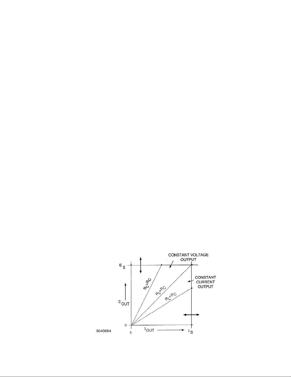
1.2 GENERAL DESCRIPTION
The KLN 750W power supply is a voltage and current stabilized d-c source with a sharp crossover between the constant voltage and constant current mode of operation. Eleven models are
offered, with rated d-c output voltage ranging from 6V to 600V and rated d-c output current ranging from 1.25A to 100A (see Table 1-1).
KLN 750W switching power supplies operate from wide range 100-240V a-c, 50/60 Hz input
source power and employ active power factor correction (PFC). Since there are no internal
adjustments, KLN 750W Power Supplies offer excellent output voltage/current stability and easy
calibration.
Output voltage and current are displayed on independent LED displays. Control of the KLN
750W can be either local, via the front panel controls and displays, or remote, using 1) either
analog signals (applied to the Programming Control Port), or 2) digital programming. Digital programming of standard models is via RS-485 communication bus. Optional IEEE 488.2 (GPIB)
and LAN interfaces are also available.
SECTION 1 - INTRODUCTION
KLN 750W output and readback are high resolution: 16 bits D/A to set output voltage and current, 24 bits A/D for readback of output voltage and current. These units feature a low temperature coefficient: Constant Voltage mode: 100ppm/°C, Constant Current mode: 300ppm/°C, and
built-in remote sensing with a maximum compensation of 5V.
The KLN 750W series is suitable for ATE automatic test, burn- in test and other applications that
require lots of testing power.
The KLN 750W power supply acts as a constant voltage source for comparatively large values
of load resistance, and as a constant current source for comparatively small values of load
resistance. The transition between these two modes of operation occurs automatically at a “critical” or “crossover” value of load resistance Rc = Es/Is, where Es is the voltage control setting
and Is is the current control setting (see Figure 1-1).
FIGURE 1-1. KLN 750W POWER SUPPLY, AUTOMATIC CROSSOVER CHARACTERISTICS
KLN 750W 032614 1-1
Page 12

1.3 SPECIFICATIONS
Table 1-1 below indicates parameters that vary for different KLN 750W models; Table 1-2 lists
general specifications that apply to all KLN 750W models.
TABLE 1-1. KLN 750 WATT MODEL PARAMETERS
d-c Output Range
Constant
Model
(8)(9)(11)(12)
KLN 6-100 0 to 6 0 to 100 10 180 2.8 11 2.8 23 0.08 0.05 0.6 1
KLN 8-90 0 to 8 0 to 90 10 180 2.8 11 2.8 23 0.08 0.05 0.6 1
KLN 20-38 0 to 20 0 to 38 10 76 4 5.8 4 12.6 0.08 0.05 0.8 1
KLN 30-25 0 to 30 0 to 25 10 63 5 4.5 5 10 0.08 0.08 0.9 1.5
KLN 40-19 0 to 40 0 to 19 10 48 6 3.9 6 8.8 0.08 0.08 1 2
KLN 60-12.5 0 to 60 0 to 12.5 10 38 8 3.25 8 7.5 0.08 0.08 1.1 3
KLN 80-9.5 0 to 80 0 to 9.5 10 29 10 2.95 10 6.9 0.15 0.15 1.2 4
KLN 100-7.5 0 to 100 0 to 7.5 10 23 12 2.75 12 6.5 0.15 0.15 1.5 5
KLN 150-5 0 to 150 0 to 5 16 18 17 2.5 17 6 0.15 0.15 2 5
KLN 300-2.5 0 to 300 0 to 2.5 25 13 32 2.25 32 5.5 0.15 0.15 3 5
KLN 600-1.25 0 to 600 0 to 1.25 75 8 62 2.13 62 5.26 0.25 0.3 4 5
NOTES:
1. Actual output voltage should be
2. Actual output current should be
3. Measured when output is within 10%-100% of rated value; ripple bandwidth: 300kHz (rms), noise bandwidth: <20MHz (p-p).
4. For 6V model: measured when output voltage 2-6V and rated current; all other models measured when output 10-100% of rated voltage and rated
current.
5. Input voltage 100-240V a-c, 50/60Hz.
6. Constant input voltage and output from 10% of loading to full load.
7. With rated input, resistive load.
8. Rated power output with input 115V or 230V a-c
9. Specifications met after 30 minutes of operation, ambient temperature 23±5°C, humidity under 80% R. H, a-c input voltage ±5% of nominal, THD
≤2%, not using the remote compensation, not operating in series or parallel.
10. For example, the spec for KLN 6-100 line regulation and load regulation in CV mode is 0.05% + 2.8mV (or 6 x 0.0005 = ±3mV +2.8mV =5.8mV), so
line and load regulation are within 0.2mV to 5.8mV for the 6V model.
11. Add G suffix for models with optional GPIB interface, add E suffix for optional LAN interface.
12. Specifications subject to change without notice.
Vol tag e
(CV)
V d-c A d-c
Constant
Current
(1)
(CC)
(2)
≤0.1% of rated voltage when output voltage is set to zero.
≤0.1% of the rated current when output current is set to zero (resistive load).
Ripple
CV
mV
rms
(3)
Line Regulation
(4)
CC
mA
rms
CV CC
0.05%mV0.1%mV0.05%mV0.1%
(5)
Load Regulation
(6)
CV
CC
mV
(10)
Response Time
Full
(6)
Full
Load
Load
Up
Down
Sec Sec Sec V
(7)
No
Load
Down
Remote
Sense
Voltage
drop
(max.)
1-2 KLN 750W 032614
Page 13

TABLE 1-2. KLN 750W GENERAL SPECIFICATIONS
SPECIFICATION RATING/DESCRIPTION
INPUT CHARACTERISTICS
Input voltage 100~240Vac, 50/60Hz
127~373V d-c
Input current (Full load) 115Vac - 8.1A; 230V a-c - 4.1A
Inrush current 230Vac - 12.5A
Power Factor (PF) 0.99 (at 115V a-c, rated output)
(1)
OUTPUT CHARACTERISTICS
Type of Stabilizer Constant Voltage (CV)/Constant Current (CC),
Adjustment Range Voltage:
Current:
Protective functions Programmable overvoltage (OVP),
Protection setting range Overvoltage:
Overcurrent:
Remote Error Sense Compensation 5V max. (See Table 1-1.)
Parallel Operation Up to 5 units maximum, automatic load sharing
Series Operation 2 units maximum (total voltage must not exceed 600V)
Temperature. Coefficient Constant Voltage Mode,
Constant Current Mode:
automatic crossover
0 to 100% of rated voltage
0 to 100% of rated current
Programmable overcurrent (OCP),
Overtemperature (OTP),
Fuse blown
0% to 110% of rated voltage
10% to 110% of rated current
100ppm/°C of rated output voltage or current, after 30 minute warm-up
Temperature. Drift Constant Voltage Mode,
Constant Current Mode:
Transient response time Constant Voltage mode: 20V and under:
Efficiency 76% – 87%
Power Factor (PF) 0.99 (at 155/230 V a-c, rated output)
Isolation Voltage Input - Outputs:
Input - Ground:
Output - Ground (6V-150V)
Output - Ground (300V-600V)
0.05% of rated output voltage or current over 8hrs interval
following 30 minutes warm-up. Constant line, load and temperature.
≤1.5ms;
30V~100V:
150V~600V:
2000V a-c: 1 minute
2000V a-c: 1 minute
500V d-c, leakage current: 100
1200V d-c, leakage current: 100
≤1ms
≤2ms
µA
µA
PROGRAMMING CHARACTERISTICS - LOCAL
Display resolution Voltage and Current: 4 digits (setting and display)
Display setting accuracy Voltage:
Current:
Display reading accuracy Voltage:
Current:
(1) Connect (+) to L and (–) to N. Safety agency approvals apply to a-c input operation only.
(2) C = 1 count of the last displayed digit.
±0.1% ± 3C
±0.5% ± 3C
±0.2% ± 3C
±0.5% ± 3C
(2)
at rated voltage
(2)
at rated current
(2)
at rated voltage
(2)
at rated current
KLN 750W 032614 1-3
Page 14

TABLE 1-2. KLN 750W GENERAL SPECIFICATIONS (CONTINUED)
SPECIFICATION RATING/DESCRIPTION
PROGRAMMING CHARACTERISTICS - DIGITAL
Command setting resolution ±0.002% of full scale
Command reading resolution ±0.002% of full scale
Command and D/A
setting accuracy
Command and A/D
Measurement accuracy
Command response time
Voltage:
Current:
Voltage:
Current:
±0.1% ± 3C
±0.5% ± 3C
±0.2% ± 2C
±0.5% ± 3C
≤20ms (After received)
(1)
at rated voltage
(1)
at rated current
(1)
at rated voltage (Average Measurement)
(1)
at rated current (Average Measurement)
(2)
RS-485 Digital Interface
(standard)
Max. effective control distance: 1000 meters.
GPIB Digital Interface Optional
LAN Digital Interface Optional
Max baud rate: 115,200
Max number of units
connected to bus:
254
PROGRAMMING CHARACTERISTICS - ANALOG
Analog setting accuracy
Constant Voltage mode (CV): Voltage:
Current:
Constant Current mode (CC): Voltage:
Current:
Analog monitor accuracy Rated voltage output: 10.00V ± 0.25V
Zero voltage output: 0.00V ± 0.25V
Rated current output: 10.00V ± 0.25V
Zero current output: 0.00V ± 0.25V
± 5%
± 5%
± 5%
± 5%
PHYSICAL CHARACTERISTICS
Weight Less than 11.2 lbs (5.1 Kg)
Dimensions W x H x D: 8.46" x 1.73" x 18.5" (215mm x 44mm x 470mm)
Source Power Connector IEC 320 inlet
Load Connections 6V to 100V models:
150V to 600V models:
Programming Control port 26-pin connector
SER IN port 2-position Euroblock (mating connector supplied)
Sense port 3-position Euroblock (mating connector supplied)
RS-485 port 3-position Euroblock (mating connector supplied)
LAN port (optional) RJ 45 connector
GPIB port (optional) Standard IEEE 488.2 GPIB connector
(1) C = 1 count of the last displayed digit.
(2) Programming time = Command response time + Output response time. The output response time differs for different models,
from 30mS ~ 200mS
± bus bars with protective cover
5-position Euroblock
1-4 KLN 750W 032614
Page 15

TABLE 1-2. KLN 750W GENERAL SPECIFICATIONS (CONTINUED)
SPECIFICATION RATING/DESCRIPTION
GENERAL (ENVIRONMENTAL) SPECIFICATIONS
Temperature Operating:
Storage:
Humidity Operating:
Storage:
Altitude 3000m max
Cooling Speed-Controlled Fan
Noise <70 dB (A)
EMC Standard EN 61326-1:2006
EMC Emissions (EN 61326-1) Conducted Disturbance: EN 55011:2007 +A2:2007 Class B
Radiated Disturbance: EN 55011:2007 +A2:2007 Class B
Harmonic Distortion: EN 61000-3-2:2006 Class A
Voltage Fluctuations
and Flicker:
EMC Immunity (EN 61326-1) Electrostatic Discharge (ESD): EN 61000-4-2:2009 Class B
Radiated RF Magnetic Field: EN 61000-4-3:2006 + A1:2008 + A2:2010 Class A
Electrical Fast Transients and
Bursts:
Surge: EN 61000-4-5:2006 Class B
Conducted Disturbance
Induced by RF Fields:
0 to 50°C (indoor use)
-20 to 70°C
30%~90% RH (no condensation)
10%~90% RH (no condensation)
EN 61000-3-3:2008 Section 5
EN 61000-4-4:2004 + A1:2010 Class B
EN 61000-4-6:2009, Class A
Voltage Dips and Short
Interruptions:
NOTE:
All specifications apply after power on for 30 minutes, ambient temperature: 23±5°C, Humidity: under 80% RH, AC Voltage: ±5%,
Frequency: ±5%.
EN 61000-4-11:2004, Class C
KLN 750W 032614 1-5
Page 16
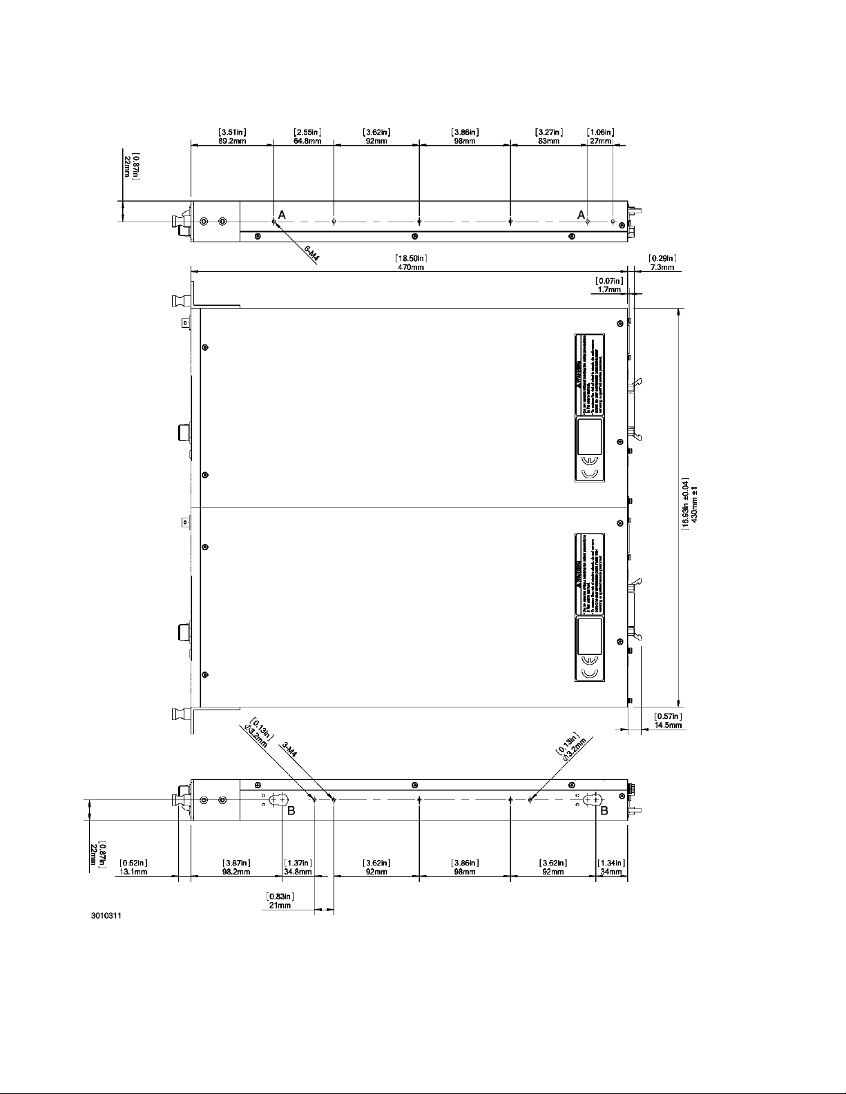
FIGURE 1-2. KLN 750W POWER SUPPLY, OUTLINE DRAWING (TWO UNITS MOUNTED IN RACK)
(SHEET 1 OF 2)
1-6 KLN 750W 032614
Page 17
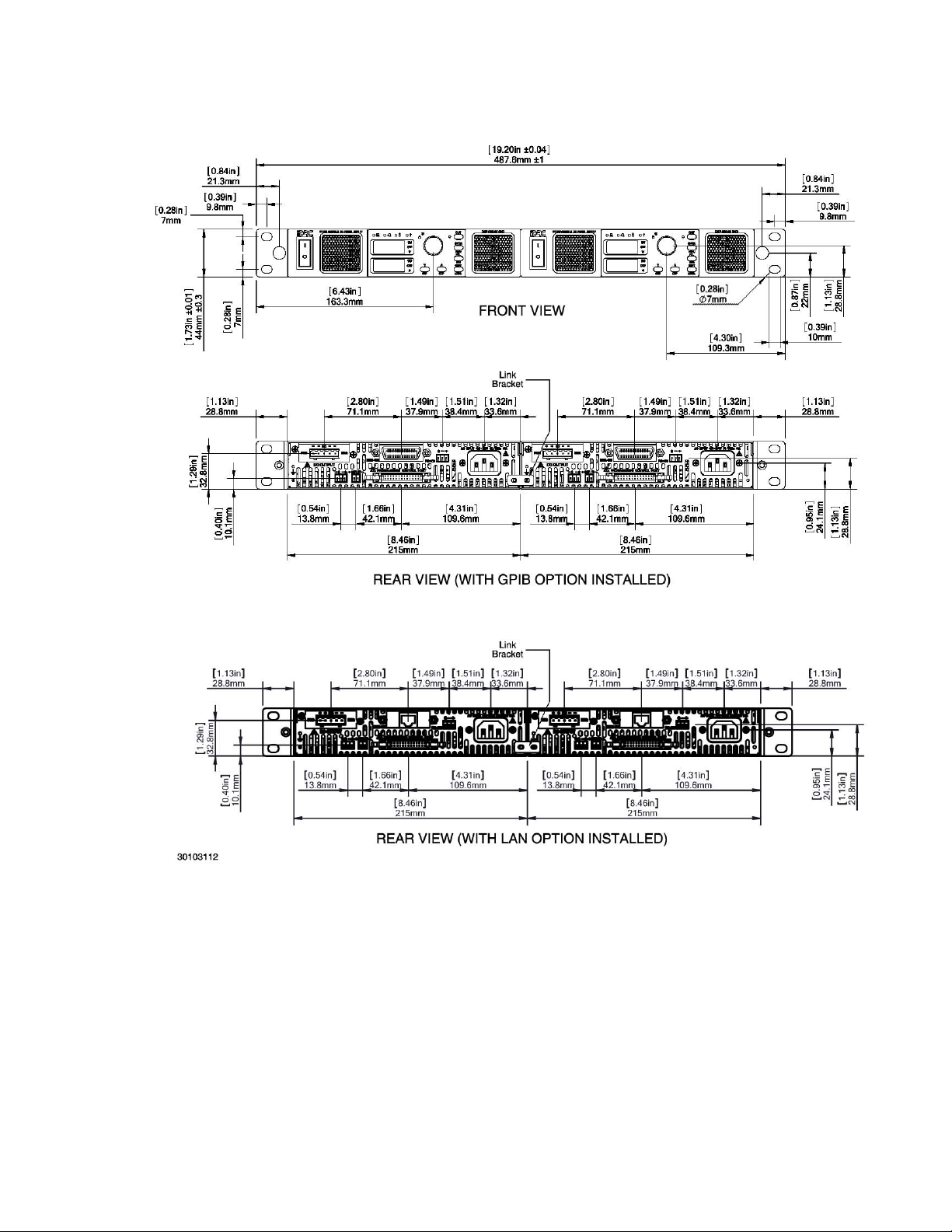
FIGURE 1-2. KLN 750W POWER SUPPLY, OUTLINE DRAWING (SHEET 2 OF 2)
1.4 LOCAL CONTROL
The front panel encoder can set and adjust output voltage and current under local control. The
display uses two 4-digit LED displays to provide a digital readout of output voltage and current.
1.5 REMOTE CONTROL
The KLN 750W Power Supply can be remotely controlled directly via the built-in RS-485 interface using SCPI commands (see Appendix A and B). Most features available in local mode can
also be accessed remotely via the RS-485 (standard), and GPIB (optional) or LAN (optional)
KLN 750W 032614 1-7
Page 18

digital interfaces. The transmission rate of RS-485 can be up to 115.2K bps. The RS-485 interface can be used to connect multiple power supplies, up to a maximum of 254 units. The maximum effective control distance can be up to 1000m.
Digital remote control is also available via optional GPIB (suffix G) and LAN (suffix E) interfaces.
1.6 ANALOG CONTROL
External reference signals, provided through the Programming Control port (see Table 2-4), can
be used to control the output voltage and current of the KLN 750W. The Programming Control
port allows control of output on/off and permits emergency shutdown of the output. Output signals allow remote monitoring of whether the unit is powered on, output on/off, alarm condition,
output voltage and current, and operating mode: Constant Current (CC) or Constant Voltage
(CV). Refer to PAR. 3.5 for further details on using external signals to control and monitor the
output.
1.7 FEATURES
1.7.1 DIGITAL CALIBRATION
The KLN 750W Power Supply features high stability and long intervals between calibration. The
unit contains no user-required internal adjustments. Calibration is done by means of software
(see Section 4).
1.7.2 PROTECTION
The following protection is provided: OVP (Overvoltage protection), OCP (overcurrent protection), OTP, (overtemperature protection) and blown fuse.
1.7.3 SAVING AND RECALLING SETTINGS
The KLN 750W offers 16 memory locations accessible from the front panel that can be used to
store a set of operating parameters for later use. For each location, the user can store voltage
and current values. The stored settings can then be recalled to quickly program the unit to the
predetermined setting. Refer to PAR. 3.3.6 and 3.3.7 for further details.
1.7.4 PARALLEL AND SERIES CONFIGURATIONS
Identical KLN 750W units may be configured in series (up to two units including master) or parallel (up to five units including master) configurations. Parallel configurations provide for automatic current sharing (see PAR. 2.8 for details).
1.7.5 MISCELLANEOUS FEATURES
• Both positive and negative output ramps can be independently programmed (see PAR’s.
3.3.10 and 3.3.11).
• Last setting is automatically restored upon power-up. Output can be programmed to be
either on or off upon power-up (see PAR’s. 3.3.9).
• One key recall of up to 16 memory locations storing voltage and current settings (see
PAR’s. 3.3.26 and 3.3.7).
• Variable speed fan reduces noise and extends fan life.
• Non-gap stacking; No ventilation holes at top or bottom.
1-8 KLN 750W 032614
Page 19
1.8 EQUIPMENT SUPPLIED
Equipment supplied with the KLN 750W power supply is listed in Table 1-3.
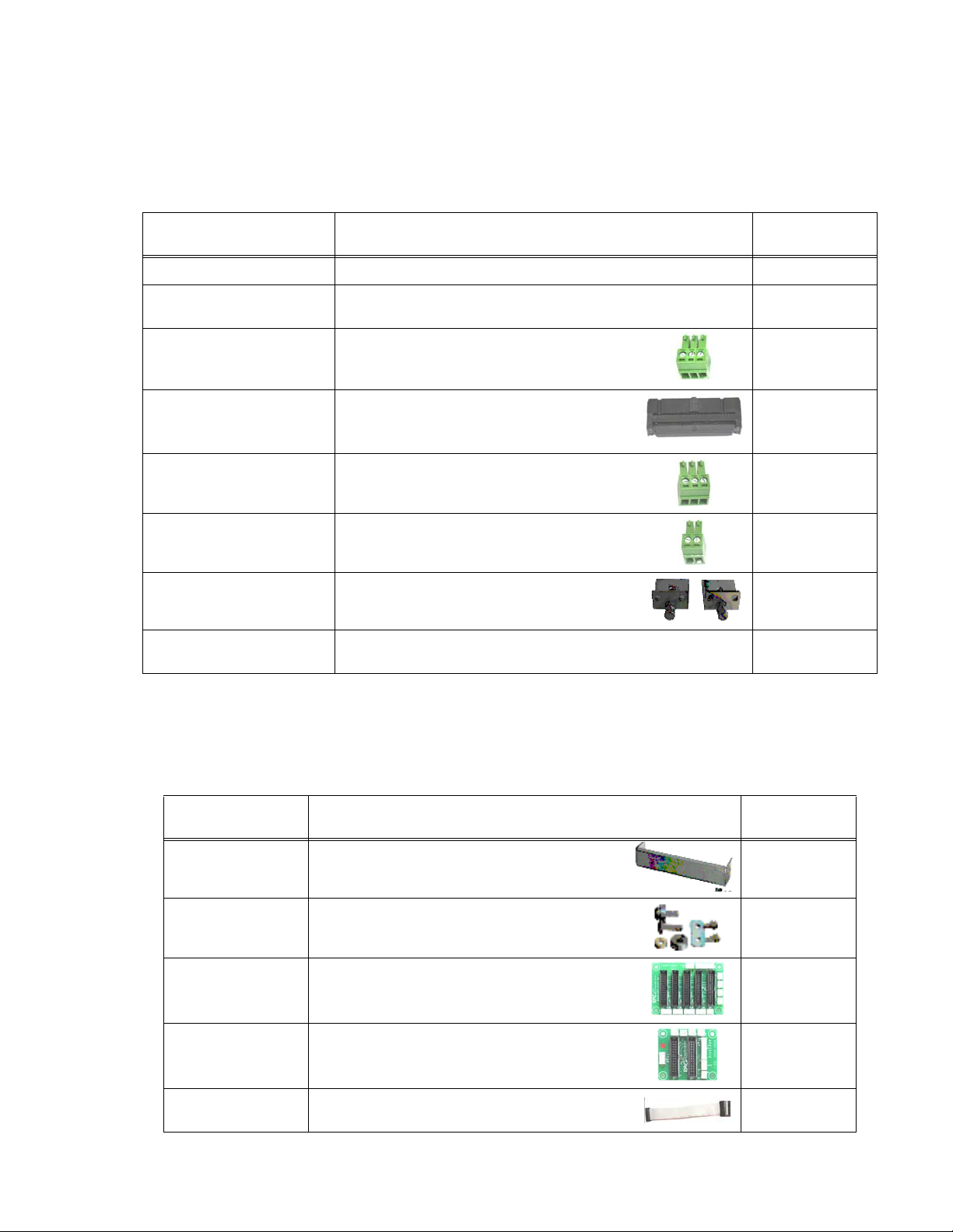
TABLE 1-3. EQUIPMENT SUPPLIED
ITEM DESCRIPTION
Power Cable, (125V/15A) Connects unit to 115V a-c source power. 118-1136
Sense wires: Red, black Used to connect output to local sensing
RS-485 Mating connector Supplied installed on RS-485 port to allow access
Programming Control Port
Mating connector
Sense Mating Connector Supplied installed on Sense connector to provide
SER IN mating connector Supplied installed on SER IN connector to allow
L-type Brackets (2) with
mounting screws (4)
Output Protective Cover Supplied with 6V through 100V models only; used
connections: red: (+) to +S, black: (–) to –S
to RS 485 interface.
Supplied installed on Programming Control port to
allow access to pins for analog control and
monitoring.
access to sense connections used to compensate
for voltage drop on load connections
series connection of two units.
Used with optional rack mounting Kits RA 81-1 or
RA 81-2 to install one or two units in 19-inch rack.
to cover output terminals
KEPCO PART
NUMBER
N/A
542-0037
143-0394
542-0035
542-0036
N/A
N/A
1.9 ACCESSORIES
Accessories (not supplied) for the KLN 750W Power Supply are listed in Table 1-4.
TABLE 1-4. ACCESSORIES
ITEM FUNCTION
Rack Mount Kit Allows mounting of one half-rack KLN 750W unit in
standard 19-inch rack (L-type brackets supplied with
unit, not included in Kit).
Rack Mount Kit Allows mounting of two half-rack KLN 750W units
side-by-side in standard 19-inch rack (L-type brackets
supplied with unit, not included in Kit).
Parallel Socket Board Provides convenient connections for parallel
Series Socket Board Provides convenient connections for series operation
Programming Port
Cable
operation of up to five units
of two units.
Provides connections between two programming
ports for parallel and series operation.
KEPCO
PART NUMBER
RA 81-1
RA 81-2
536-0129
536-0130
518-0119
KLN 750W 032614 1-9
Page 20
1.10 SAFETY
Service must be referred to authorized personnel. Using the power supply in a manner not
specified by Kepco. Inc. may impair the protection provided by the power supply. Observe all
safety precautions noted throughout this manual (see listing on Safety page A, preceding the
Table of Contents). Table 1-5 lists symbols used on the power supply or in this manual where
applicable.
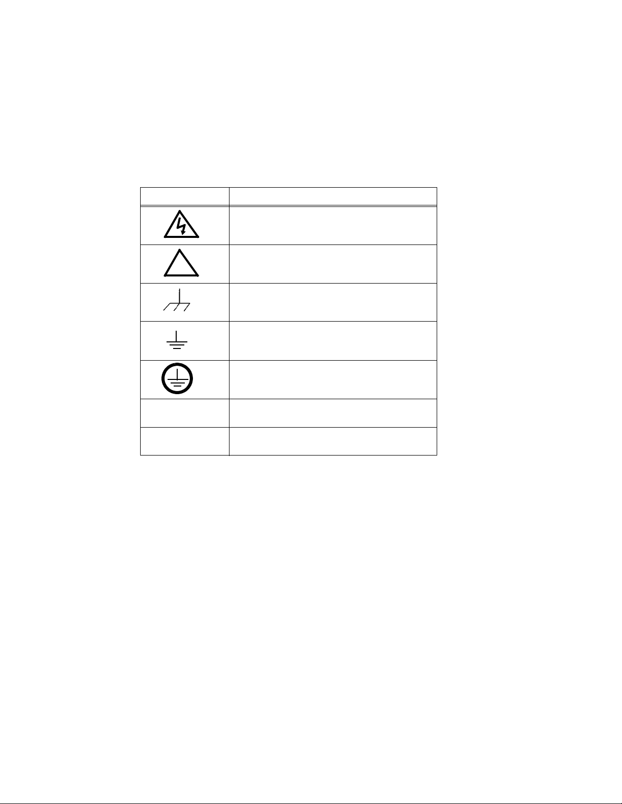
TABLE 1-5. SAFETY SYMBOLS
SYMBOL Meaning
WARNING! RISK OF ELECTRIC SHOCK!
CAUTION: REFER TO REFERENCED PROCEDURE.
!
FRAME OR CHASIS TERMINAL
GROUND TERMINAL
PROTECTIVE GROUND CONDUCTOR TERMINAL
WARNING
CAUTION
INDICATES THE POSSIBILITY OF BODILY INJURY
OR DEATH.
INDICATES THE POSSIBILITY OF EQUIPMENT
DAMAGE.
1-10 KLN 750W 032614
Page 21
SECTION 2 - INSTALLATION
2.1 UNPACKING AND INSPECTION
This instrument has been thoroughly inspected and tested prior to packing and is ready for
operation. After careful unpacking, inspect for shipping damage before attempting to operate.
Perform the preliminary operational check as outlined in PAR. 2.3. If any indication of damage is
found, file an immediate claim with the responsible transport service.
2.2 TERMINATIONS AND CONTROLS
a) Front Panel: Refer to Figure 3-1 and Table 3-1.
b) Rear Panel: Refer to Figure 2-1 and Table 2-1.
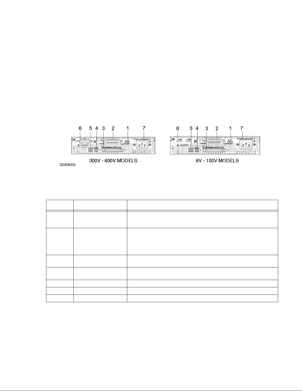
FIGURE 2-1. KLN 750W SERIES REAR PANEL
TABLE 2-1. REAR PANEL CONNECTOR FUNCTIONS
NUMBER
(FIGURE 2-1)
1
2
3 Programming Control Port
4 SER IN
5 +S, –S Remote sensing voltage compensation.
6 DC Output Allows connection to load.
7 AC input Allows connection to mains supply using power cord supplied.
CONNECTOR/TERMINAL FUNCTION
RS-485
3-pin pluggable terminal
block
Optional:
either 24-pin GPIB
connector (shown)
or LAN ethernet connector
(not shown)
Allows connection to RS-485 bus. See Table 2-2 for details.
Allows connection to GPIB bus or LAN (optional) when installed. See Table 2-3 for
GPIB connector details.
Allows access to analog input/output signals that allow monitoring and control of the
power supply by analog means. See Table 2-4 for pin assignments.
Provides output voltage reference from master to slave to ensure voltage slave
matches the master when two units connected in series.
KLN 750W 032614 2-1
Page 22
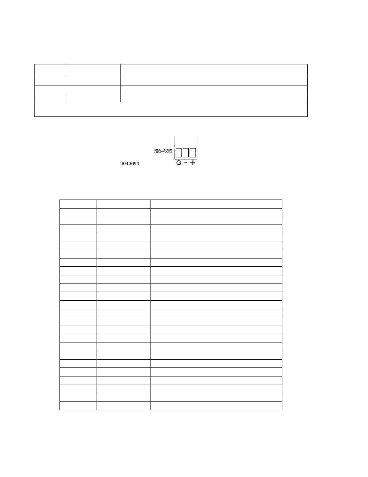
TABLE 2-2. RS-485 PORT INPUT/OUTPUT PIN ASSIGNMENTS
PIN
(FIGURE 2-2)
G Ground Reduce external interference
+ +RX Connect to +TX of computer and/or +RX of next unit on RS-485 bus (see Figure 2-9).
– –RX Connect to –TX of computer and/or –RX of next unit on RS-485 bus (see Figure 2-9).
NOTE: Connect 120 Ohm termination resistor across + and – of last unit connected to RS-485 bus (furthest from computer)
See PAR. 2.7.2.
SIGNAL NAME FUNCTION
FIGURE 2-2. RS-485 PORT
TABLE 2-3. GPIB (IEEE 488) PORT INPUT/OUTPUT PIN ASSIGNMENTS
PIN SIGNAL NAME FUNCTION
1DI01 I/O Line
2D
3D
4D
5 EOI End or Identify
6 D AV Da ta Vali d
7 NRFD Not Ready for Data
8 NDAC Not Data Accepted
9 IFC Interface Clear
10 SRQ Service Request
11 ATN Attention
12 SHIELD Shield
13 D
14 D
15 D
16 D
17 REN Remote Enable
18 GND Ground (signal common)
19 GND Ground (signal common)
20 GND Ground (signal common)
21 GND Ground (signal common)
22 GND Ground (signal common)
23 GND Ground (signal common)
24 LOGIC GND Logic Ground
I02 I/O Line
I03 I/O Line
I04 I/O Line
I05 I/O Line
I06 I/O Line
I07 I/O Line
I08 I/O Line
2-2 KLN 750W 032614
Page 23
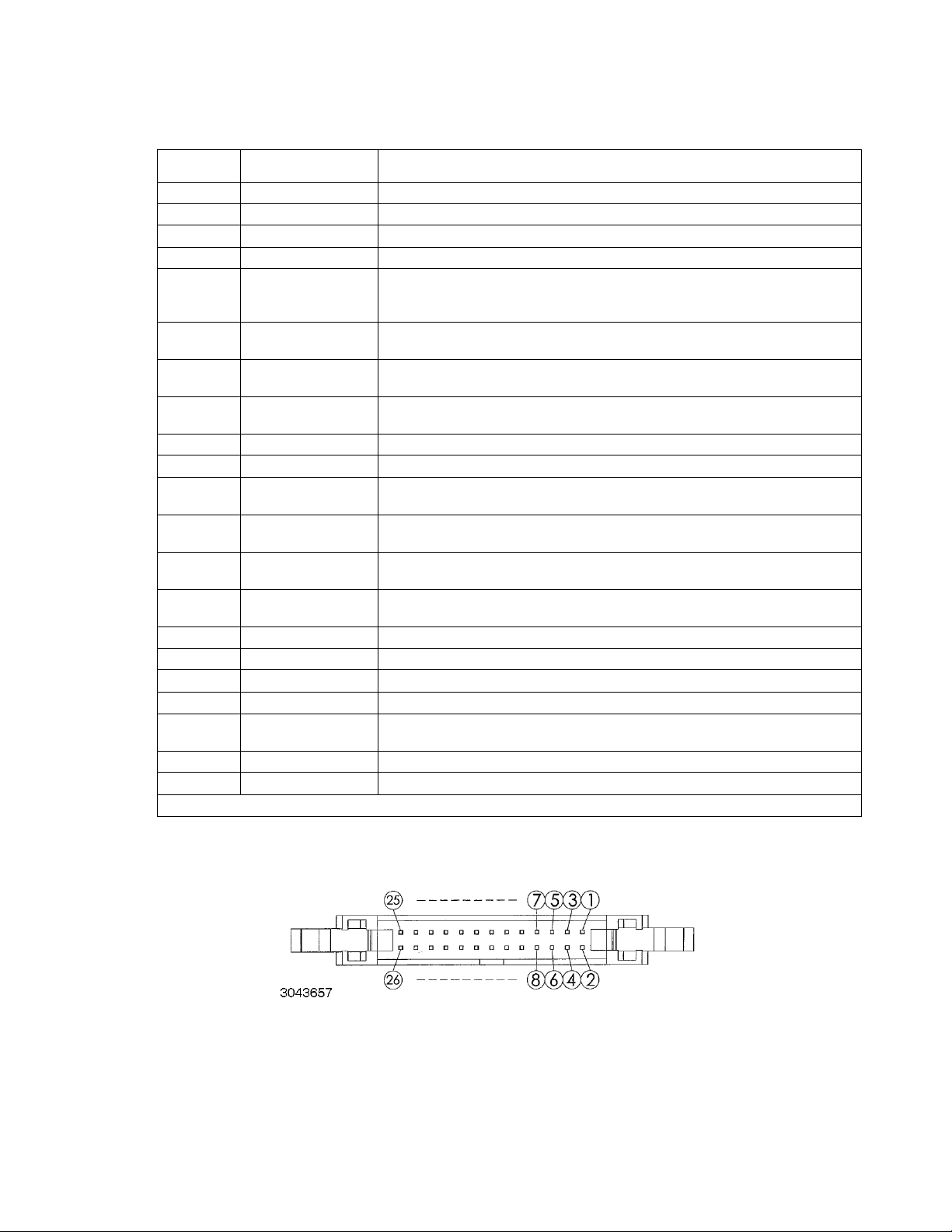
TABLE 2-4. PROGRAMMING CONTROL PORT I/O PIN ASSIGNMENTS
PIN
(FIGURE 2-3)
1, 2 RECALL External recall control (dry contact). Same function as RCL key on front panel.
3, 4, 5, 6 --- Not used
7 Power on/off status Output signal. Active (low between pin 7 and pin 8) to indicate unit is turned on.
8 Status common Common for Status signal pins 7, 9, 10, 11 and 12
9 Alarm status
10 On/off status
11 CC status
12 CV status
13 EXT 5V input+ Input signal. Used to supply +5V for the relay providing remote output on/off function.
14 EXT V input common Common for Pin 13 (remote output on/off function).
15 PRL IN+
16 EXT CV
17 PRL OUT+
18 EXT CC
19 PRL IN–/OUT– V common for pins 15 and 17.
20 V Monitor Output signal. Zero to 10V d-c corresponds to zero to full scale voltage,
21 ON/OFF Control Input Signal. Used to power unit on (short) or off (open). Dry contact.
22 A Monitor Output signal. Zero to 10V d-c corresponds to zero to full scale current.
23 Shutdown
24, 26 Analog Common Analog signal control ground, connected to pin 19.
25 Digital Common Digital signal control ground.
(1) Open collector output: maximum voltage 30V, maximum current 8mA; Low: <0.4V.
SIGNAL NAME FUNCTION
Output signal. Active (low between pin 9 and pin 8) to indicate whether alarm (OVP or
OCP trips or shutdown signal applied to pin 23) has occurred. (open collector via optocoupler).
Output signal. Active (low between pin 10 and pin 8) to indicate output is on (open collector by optocoupler).
Output signal. Active (low between pin 11 and pin 8) to indicate unit is in constant current mode (open collector by optocoupler).
Output signal. Active (low between pin 12 and pin 8) to indicate unit is in constant voltage mode (open collector by optocoupler).
(1)
(1)
(See PAR. 3.3.25 to enable.)
(1)
(1)
Input signal. For units operating in parallel, used for signal input into MASTER of current sharing between MASTER and SLAVE(s) (see PAR. 2.8.2.1).
Input signal. External voltage to control output voltage of unit. 0 to 10V d-c corresponds to zero to full scale output voltage (see PAR. 3.3.26 to enable).
Output signal. For units operating in parallel, used for signal output of current sharing
from SLAVE to MASTER (see PAR. 2.8.2.1).
Input signal. External voltage to control output current of unit. 0 to 10V d-c corresponds to zero to full scale output current (see PAR. 3.3.27 to enable).
Short between pin 23 and analog ground (pins 24 or 26) causes emergency shutdown
of unit.
(1)
(1)
FIGURE 2-3. PROGRAMMING CONTROL PORT
KLN 750W 032614 2-3
Page 24

2.3 PRELIMINARY OPERATIONAL CHECK
A simple operational check after unpacking and before equipment installation is advisable to
ascertain whether the power supply has suffered damage resulting from shipping.
Refer to Figures 2-1 and 3-1 for location of operating controls and electrical connections. Tables
3-1 and 3-2 explain the functions of operating controls/indicators and keypad keys, respectively.
Refer to PAR. 3.2 for a description of basic operating techniques.
1. With power supply disconnected from source power verify that sense connections are correct: +S is connected to +POS and –S is connected to –NEG (see PAR. 2-6).
2. With front panel power circuit breaker to OFF position, connect the power supply to source
power (see PAR. 2.5.2).
3. With no load connected, set power circuit breaker to ON. Each time the unit is turned on it
beeps and an internal self-test is performed (see PAR 3.2.1). After the test has been successfully completed, the 4-digit Voltage Display and Current Display show the last programmed voltage and current values, respectively, in Volts and Amperes.
4. Press SHIFT/LOCAL key. Verify blue LED goes on. Press V/OVP key: Least significant
digit of Voltage Display and integral red OVP LED at the right of the display blink. Verify
blue LED goes off.
5. Rotate encoder to change the digits for adjustment. Turn clockwise to increase the value,
counterclockwise to decrease the value. Tap encoder to move to the next digit. Continue until
the maximum OVP value is displayed (e.g., 33.00 for 30V model).
6. Press ENTER key to accept programmed OVP value.
7. Press SHIFT/LOCAL key. Verify blue LED goes on. Press A/OCP. Least significant digit
of Current Display and integral red OCP LED at the right of the display blink. Verify
blue LED goes off.
8. Rotate encoder to change the digits for adjustment. Turn clockwise to increase the value,
counterclockwise to decrease the value. Tap encoder to move to the next digit. Continue until
the maximum OCP value is displayed (e.g., 26.25 for 25 Ampere model).
9. Press ENTER key to accept programmed OCP value.
10.Press V/OVP key. Least significant digit of Voltage Display blinks.
11. Rotate encoder to change the digits for adjustment. Turn clockwise to increase the value,
counterclockwise to decrease the value. Tap encoder to move to the next digit. Continue until
the rated output voltage value (e.g., 30.00 for 30V model) is displayed.
12.Press ENTER key to accept programmed voltage value.
13.Press A/OCP key. Least significant digit of Current Display blinks.
14.Rotate encoder to change the digits for adjustment. Turn clockwise to increase the value,
counterclockwise to decrease the value. Tap encoder to move to the next digit. Continue until
a value of several Amperes of output current is displayed.
2-4 KLN 750W 032614
Page 25

15.Connect a digital voltmeter (DVM) to the (+S) and (-S) terminals on the rear panel. Verify that
DVM shows there is no output voltage from the power supply.
16.Press red OUT key. Verify that red LED at left of OUT key goes on.
17.Compare the programmed output voltage value (e.g., 30.00V for 30V model per step 11) with
the voltage reading of the DVM; Verify that the difference between the two does not exceed
±0.1% ± 3C
(*)
.
18.Compare the voltage reading of Voltage Display with that of the DVM; Verify that the difference between the two does not exceed ±0.2% ± 3C
19.Disable the output by pressing the OUT key; verify front panel Voltage and Current displays
show programmed values of Voltage and Current, respectively and DVM reads 0V.
20.Set power switch to OFF. The unit issues a long beep as it powers down. Disconnect unit
from source power, then disconnect test equipment.
(*) C = 1 count of the last displayed digit.
2.4 INSTALLATION
2.4.1 RACK MOUNTING
One or two (side by side) KLN 750W units can be mounted in a standard 19-inch rack. The units
are 1U high and do not require any gaps between equipment above and below. Airflow is front
to back only. Use the RA 81-1 Mounting Kit (see Table 1-4) to mount a single unit. Use Mounting
Kit RA 81-2 (optional, see Table 1-4) to mount two half-rack units side by side in a 19-inch rack.
2.4.1.1 MOUNTING ONE 1/2-RACK UNIT IN 19-INCH RACK
1. On one side of the unit, mount one L-type bracket with knob (supplied with unit) to the unit
using two screws supplied with unit.
(*)
.
2. Mount the U-type bracket supplied in the Kit to the other side of the unit using two screws
supplied in Kit.
3. Mount the other L-type bracket with knob (supplied with unit) to the end of the U-type bracket
using two screws supplied with unit. The knobs can now be used to support the assembled
unit while installing in a 19-inch rack.
KLN 750W 032614 2-5
Page 26
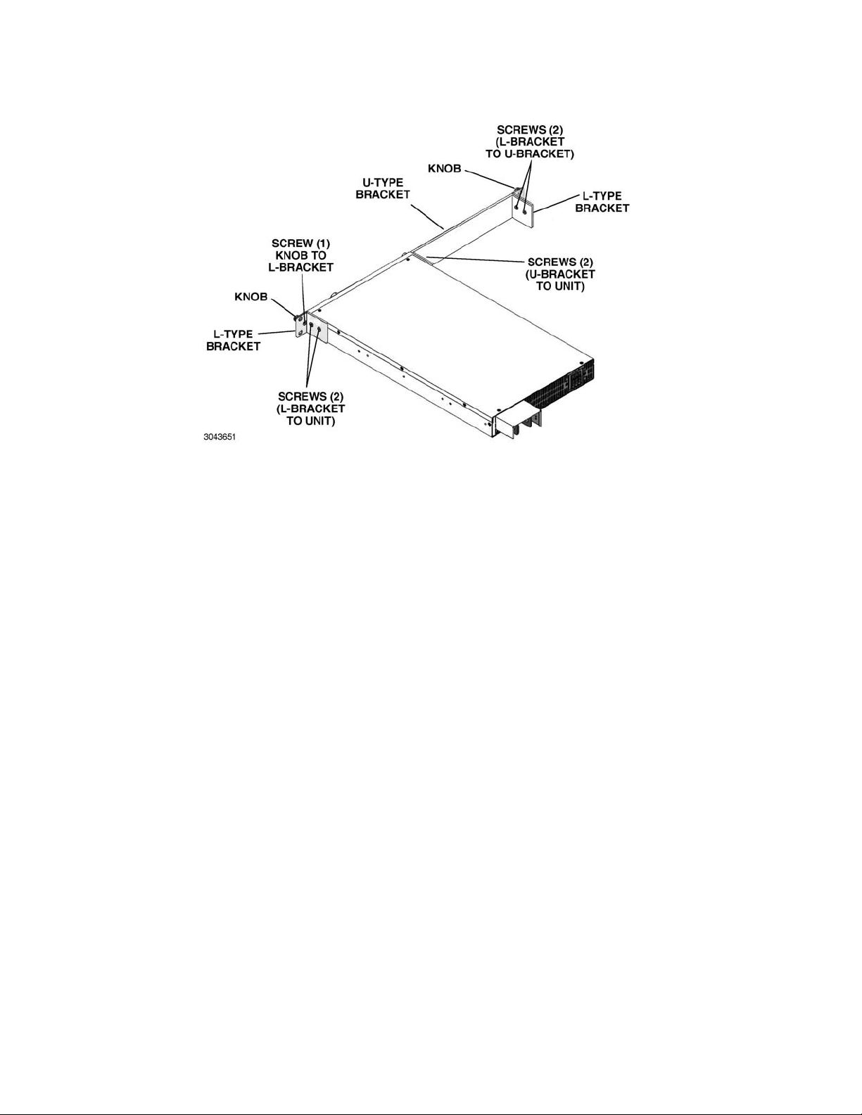
FIGURE 2-4. MOUNTING ONE KLN 750W UNIT IN 19-INCH RACK
2.4.1.2 MOUNTING TWO 1/2-RACK UNITS IN 19-INCH RACK
To mount two KLN 750W units side-by-side in a 19 inch rack, use the RA 81-2 mounting kit (not
supplied, see Accessories, Table 1-4).
1. Place the two units side by side as they would be installed in the rack. On the outer side of
each unit (not facing the other unit), mount one L-type bracket with knob (supplied with unit)
to each unit using two screws supplied with unit for each (see Figure 1-2).
2. Separate the two units. Install two shoulder screws, flat washers and lockwashers (supplied
with Kit) at two locations on one unit (two threaded holes, A, Figure 1-2).
3. Move the two units together and insert the shoulder screws into the keyhole-shaped opening
in the other unit (two holes, B, Figure 1-2). Then slide the unit with the shoulder screws forward until the front panels of both units are flush.
4. Connect the two units at the rear using linking bracket (see Figure 1-2, sheet 2) and two
screws supplied with Kit. The two units can now be handled as an assembly and can be
installed directly into a 19-inch rack.
2.5 WIRING INSTRUCTIONS
Interconnections between an a-c power source and a power supply, and between the power
supply and its load are as critical as the interface between other types of electronic equipment.
If optimum performance is expected, certain rules for the interconnection of source, power supply and load must be observed by the user. These rules are described in detail in the following
paragraphs.
2-6 KLN 750W 032614
Page 27

CAUTION: WHEN WORKING WITH ACTIVE LOADS, THE VOLTAGE OR CURRENT OF
THE ACTIVE LOAD MUST NOT EXCEED THE MAXIMUM VOLTAGE OR CURRENT RATING OF THE KLN 750W. OTHERWISE THE OVERVOLTAGE OR
OVERCURRENT PROTECTION WILL SHUT DOWN THE POWER SUPPLY.
2.5.1 SAFETY GROUNDING
To minimize shock hazard, the product chassis must be connected to an electrical ground. The
product must be connected to the AC power supply mains through a three-conductor power
cable, with the ground wire firmly connected to an electrical ground (safety ground) at the power
outlet.
Local, national and international safety rules dictate the grounding of the metal cover and case
of any instrument connected to the a-c power source, when such grounding is an intrinsic part of
the safety aspect of the instrument. The ground terminal of the source power connector (Figure
2-1) is connected to the chassis and the instructions below suggest wiring methods which comply with these safety requirements. In the event that the specific installation for the power system is different from the recommended wiring, it is the customer's responsibility to ensure that
all applicable electric codes for safety grounding requirements are met. As a precaution, always
connect the screw marked at the rear panel to proper earth ground.
2.5.2 SOURCE POWER CONNECTIONS
Source power is connected to the power supply via three-wire input power using the source
power cable supplied (see Table 1-3). See Table 1-2 for source power specifications. This power
supply operates from single phase a-c mains power (or between two phases of 3-phase a-c
mains power) over the specified voltage and frequency ranges (Table 1-2) without any need for
range selection.
CAUTION: DO NOT USE AC SUPPLY WHICH EXCEEDS THE INPUT VOLTAGE AND FRE-
QUENCY RATING OF THIS INSTRUMENT. THE INPUT VOLTAGE AND FREQUENCY RATING OF THE POWER SUPPLY ARE SHOWN IN TABLE 1-2. FOR
SAFETY REASONS, THE MAINS SUPPLY VOLTAGE FLUCTUATIONS MUST
NOT EXCEED ±10% OF NOMINAL VOLTAGE.
2.5.3 D-C OUTPUT GROUNDING
Connections between the power supply and the load and sensing connections may, despite all
precautions such as shielding, twisting of wire pairs, etc., be influenced by radiated noise, or
“noise pick-up”. To minimize the effects of this radiated noise the user should consider grounding one side of the power supply/load circuit. The success of d-c grounding requires careful
analysis of each specific application, however, this recommendation can only serve as a general
guideline.
One of the most important considerations in establishing a successful grounding scheme is to
avoid GROUND LOOPS. Ground loops are created when two or more points are grounded at
different physical locations along the output circuit. Due to the interconnection impedance
between the separated grounding points, a difference voltage and resultant current flow is
superimposed on the load. The effect of this ground loop can be anything from an undesirable
increase in output noise to disruption of power supply and/or load operation. The only way to
avoid ground loops is to ensure that the entire output/load circuit is fully isolated from ground,
and only then establish a single point along the output/load circuit as the single-wire ground
point.
KLN 750W 032614 2-7
Page 28

The exact location of the “best” d-c ground point is entirely dependent upon the specific application, and its selection requires a combination of analysis, good judgement and some amount of
empirical testing. If there is a choice in selecting either the OUTPUT or COMMON output terminals of the power supply for the d-c ground point, both sides should be tried, and preference
given to the ground point producing the least noise. For single, isolated loads the d-c ground
point is often best located directly at one of the output terminals of the power supply; when
remote error sensing is employed, d-c ground may be established at the point of sense lead
attachment. In the specific case of an internally-grounded load, the d-c ground point is automatically established at the load.
The (+) and (–) terminals of KLN 750W power supplies are d-c isolated (“floating”) from the
chassis in order to permit the user maximum flexibility in selecting the best single point ground
location. Care must be taken in measuring the ripple and noise at the power supply: measuring
devices which are a-c line operated can often introduce additional ripple and noise into the circuit.
There is, unfortunately, no “best” method for interconnecting the load and power supply. Individual applications, location and nature of the load require careful analysis in each case. Grounding a single point in the output circuit can be of great importance. It is hoped that the preceding
paragraphs will be of some assistance in most cases. For help in special applications or difficult
problems, consult directly with Kepco's Application Engineering Department.
2.5.4 POWER SUPPLY/LOAD INTERFACE
The general function of a voltage- or current-stabilized power supply is to deliver the rated output quantities to the connected load. The load may have any conceivable characteristic: it may
be fixed or variable, it may have predominantly resistive, capacitive or inductive parameters; it
may be located very close to the power supply output terminals or it may be a considerable distance away. The perfect interface between a power supply and its load would mean that the
specified performance at the output terminals would be transferred without impairment to any
load, regardless of electrical characteristics or proximity to each other.
The stabilized d-c power supply is definitely not an ideal voltage or current source, and practical
interfaces definitely fall short of the ideal. All voltage-stabilized power supplies have a finite
source impedance which increases with frequency, and all current-stabilized power supplies
have a finite shunt impedance which decreases with frequency. The method of interface
between the power supply output and the load must, therefore, take into account not only the
size with regard to minimum voltage drop, but the configuration with regard to minimizing the
impedance introduced by practical interconnection techniques (wire, bus bars, etc.). The series
inductance of the load wire must be as small as possible as compared to the source inductance
of the power supply: although the error sensing connection to the load compensates for the d-c
voltage drop in the power leads, it cannot compensate for the undesirable output effects of the
power lead inductance. These lead impedances (both power and sensing leads) are especially
important if the load: is constantly modulated or step-programmed; has primarily reactive characteristics; or where the dynamic output response of the power supply is critical to load performance.
2.5.5 LOAD CONNECTION - GENERAL
Power connections to the load are achieved via the +POS and –NEG DC OUTPUT terminals
located on the rear panel. Terminal connections for low voltage models (6V to 150V) are shown
in Figure 2-5. The 300V and 600V models employ Euroblock-style terminal blocks that accept
bare wire ends.
2-8 KLN 750W 032614
Page 29

FIGURE 2-5. LOAD CONNECTION TERMINALS FOR 6V - 150V MODELS
Kepco strongly recommends the use of stranded (not solid) wire with (+) and (–) wires tightly
twisted to reduce self-inductance; wire end ferrules are suggested to prevent fraying of the
strands.
NOTE REGARDLESS OF OUTPUT CONFIGURATION, EITHER LOCAL OR REMOTE OUT-
PUT SENSE LINES SHOULD BE CONNECTED FOR OPTIMUM OPERATION.
• OBSERVE POLARITIES: The +S sensing wire must be connected to the (+) load wire,
and the –S sensing wire must be connected to the (–) load wire.
• IF LOCAL SENSING IS USED: Install red and black sense leads supplied (see Figure 2-
6).
2.5.6 LOAD CONNECTION USING LOCAL SENSING
Figure 2-6 shows a typical configuration using local sensing. Local sensing is recommended for
a high noise or switching mode load such as d-c to d-c or d-c to a-c.
CAUTION: CONNECT +S ONLY TO + AND –S ONLY TO –. CONNECTING +S TO –S, +V
TO –S, OR –V TO +S WILL DAMAGE THE UNIT.
FIGURE 2-6. LOAD CONNECTIONS, LOCAL SENSING
KLN 750W 032614 2-9
Page 30

Use the following formula and Figure 2-7 to calculate the voltage drop based on expected current and wire resistance. Refer to Table 2-5 for wire resistance for standard AWG sizes, as well
as maximum recommended length of load wires for a voltage drop of less than 1V with expected
load current of 5, 10, 20, 50 or 150 Amperes.
V
= (I x r1) + (I x r2)
DROP
where r1 and r2 is the load wire resistance
I is output current
Voltage across Load RL = Voltage (displayed on front panel display) – V
DROP
FIGURE 2-7. LOAD WIRE VOLTAGE DROP, EQUIVALENT SCHEMATIC DIAGRAM
TABLE 2-5. MAXIMUM LOAD WIRE LENGTH FOR VOLTAGE DROP LESS THAN 1V
AWG
SIZE
14 2 0.8 24.4m 12.2m 6.1m 2.4m 0.6m
12 3.5 0.5 36.6m 18.3m 9.1m 3.7m 1.0m
10 5.5 0.3 61.0m 30.5m 15.2m 6.1m 1.8m
8 8 0.2 97.5m 48.8m 24.4m 9.8m 3.0m
6 14 0.1 152.4m 61m 38.1m 15.2m 4.9m
4 22 0.1 243.8m 121.9m 61.0m 24.4m 7.9m
2 38 0.1 365.7m 182.9m 91.4m 38.1m 12.2m
0 60 0.0 696m 304.8m 152.4m 61.0m 20.7m
* Values shown are rounded up.
Wire
Diameter
mm
2
Resistance*
(Ohm/100m)
Load Current5ALoad Cur-
Maximum Load Wire Length for Voltage drop less than 1V
rent 10A
Load Current
20A
Load Cur-
rent 50A
Load Current
150A
2.5.7 LOAD CONNECTION USING REMOTE SENSING
Figure 2-8 shows a typical configuration using remote sensing.
Use #22 AWG wire, twisted
pair for remote sense connections. Table 2-5 shows typical load wire length, AWG wire size
and load current required for a voltage drop of less than 1V. Table 1-1 lists the maximum
voltage drop compensation for each model that will allow voltage measured at the load to
be the same as the voltage shown on the front panel display.
2-10 KLN 750W 032614
Page 31

CAUTION: CONNECT +S ONLY TO + AND –S ONLY TO –. CONNECTING +S TO –S, +V
TO –S, OR –V TO +S WILL DAMAGE THE UNIT.
FIGURE 2-8. LOAD CONNECTIONS, REMOTE SENSING
2.6 COOLING
The power devices used within the power supply are maintained within their operating temperature range by means of internal heat sink assemblies and a variable speed fan with air flow from
front to back. There are no intake or exhaust ports at the top or bottom, permitting stacked rack
mounting with no air gaps between stacked units. If the power supply is located within a confined
space, take care that the ambient temperature, which is the temperature of the air immediately
surrounding the power supply, does not rise above the specified limits (see Table 1-2).
2.7 SETTING UP THE UNIT
The following paragraphs describe the connections and initial KLN 750W setup needed to operate in the desired mode.
2.7.1 SETUP FOR LOCAL OPERATION
After connecting the unit using either local (PAR. 2.5.7) or remote sensing (PAR. 2.5.7), the unit
will power up in Local mode with no further setup required.
2.7.2 SETUP FOR REMOTE OPERATION VIA RS-485
CAUTION: DO NOT CONNECT THE POSITIVE OUTPUT TO GROUND WHEN RS-485 IS
USED. THERE IS A POTENTIAL SHOCK HAZARD AT THE RS-485 PORT
WHEN POWER SUPPLIES ARE USED WITH RATED OR COMBINED VOLTAGE GREATER THAN 400V AND THE POSITIVE OUTPUT OF THE POWER
SUPPLY IS GROUNDED.
Connect the KLN 750W to the controlling computer or to the previous unit in the RS-485 daisy
chain per Figure 2-9. It is recommended that double shielded wire be used to ensure the quality
of remote communication. The last unit on the RS-485 bus requires a 120-Ohm terminating
resistor as shown in Figure 2-9.
With all power off, connect the load to the KLN 750W using either local or remote sensing (refer
to PAR. 2.5). If units are to be connected in series or parallel, refer to PAR. 2.8.
Turn power on and refer to PAR. 3.2 for power supply basics. See PAR. 3.3.16 to establish RS485 baud rate and PAR. 3.3.18 to establish the RS-485 Address.
SCPI programming is described in PAR. 3.7; Appendices A and B provide syntax for SCPI common and subsystem commands and queries implemented in this unit. For RS-485 communica-
KLN 750W 032614 2-11
Page 32

tion the RS-485 address (Axxx) must precede every command (e.g., to set the brightness to 3
and output voltage to 30 of a unit with RS-485 address 001, send
A001DISP:CONT 3;A001VOLT 30)
FIGURE 2-9. RS-485 CONNECTIONS
2.7.3 SETUP FOR REMOTE OPERATION VIA GPIB
CAUTION: DO NOT CONNECT THE POSITIVE OUTPUT TO GROUND WHEN IEEE 488 IS
USED. THERE IS A POTENTIAL SHOCK HAZARD AT THE IEEE 488 (GPIB)
PORT WHEN POWER SUPPLIES ARE USED WITH RATED OR COMBINED
VOLTAGE GREATER THAN 400V AND THE POSITIVE OUTPUT OF THE
POWER SUPPLY IS GROUNDED.
Operation via GPIB is possible if the optional GPIB interface is installed. With all power off, connect the load to the KLN 750W using either local or remote sensing. If units are to be connected
in series or parallel, refer to PAR. 2.8. Connect the GPIB connector to the GPIB port (see Figure
2-1 and Table 2-1). Turn power on and refer to PAR. 3.2 for power supply basics and PAR. 3.6
for remote mode programming.
The default GPIB address is 07; to change it refer to PAR 3.3.17. The unit automatically enters
remote mode when a command is accepted.
SCPI programming is described in PAR. 3.7; Appendices A and B provide syntax for SCPI common and subsystem commands and queries implemented in this unit. All the features described
for Local Mode operation can be accomplished using remote SCPI commands.
2.7.4 SETUP FOR REMOTE OPERATION VIA LAN
Operation via LAN is possible if the optional LAN interface is installed.
Connect a computer to the LAN connector at the rear panel using a standard RJ 45 Ethernet
cable (not supplied). The LAN interface uses LAN Port 8003 for Telnet connections.
See PAR. 3.6.3 to operate the unit via the LAN interface.
2.8 MULTIPLE UNIT CONFIGURATIONS
Parallel and series configurations of identical KLN 750W units increase the rated current and
voltage range of the power supply. Up to five units (including the master) can be connected in
2-12 KLN 750W 032614
Page 33

parallel to increase the current: I
of units in parallel. Similarly, up to two units (including the master) can be connected in series to
increase the voltage: E
MAX (one unit)
series.
2.8.1 SERIES CONNECTIONS
Two identical KLN 750W units can be operated in series to double the output voltage.
CAUTION: TOTAL VOLTAGE MUST NOT EXCEED 600V TO AVOID DAMAGING THE
UNITS.
See Figure 2-10 for series connections without local sensing and Figure 2-11 for series connections with remote sensing. See PAR. 3.4.1 for operating units connected in series.
MAX (one unit)
x N2 = E
x NP = I
MAX (Series combination)
MAX (parallel combination)
where NP = number
where N2 = number of units in
NOTE:
Adding local sensing wires
from + to +S and from – to –S
on both the Master and Slave
will make the front panel voltage reading slightly more
accurate (~10mV).
FIGURE 2-10. SERIES CONNECTIONS WITHOUT REMOTE SENSING
FIGURE 2-11. SERIES CONNECTIONS WITH REMOTE SENSING
2.8.1.1 SERIES CONNECTIONS USING OPTIONAL SERIES CONNECTION KIT
Connections for two identical KLN 750W units operated in series to double the output voltage
can be simplified by using the optional Series ConnectIon Kit (see Table 1-4).
CAUTION: TOTAL VOLTAGE MUST NOT EXCEED 600V TO AVOID DAMAGING THE
UNITS.
KLN 750W 032614 2-13
Page 34

FIGURE 2-12. OPTIONAL SERIES CONNECTION KIT
2.8.2 PARALLEL CONNECTIONS
Up to five identical KLN 750W units (one master and up to four slaves) can be operated in parallel to increase the output current. Output current of the parallel combination = number of units
in parallel x output current of a single unit.
1. See Figure 2-13 for parallel connections without remote sensing and Figure 2-14 for parallel
connections with remote sensing. See PAR. 2.5.5 for guideline regarding load connections.
See PAR. 3.4.3 for operating units connected in parallel.
CAUTION: OBSERVE CORRECT POLARITY FOR ALL CONNECTIONS.
2. See Figure 2-15 for Programming Control Port Connections for parallel operation.
NOTE:
Adding local sensing wires
from + to +S and from – to –S
on both the Master and Slave
will make the front panel voltage reading slightly more
accurate (~10mV).
FIGURE 2-13. PARALLEL CONNECTIONS WITHOUT REMOTE SENSING
2-14 KLN 750W 032614
Page 35

FIGURE 2-14. PARALLEL CONNECTIONS WITH REMOTE SENSING
FIGURE 2-15. PROGRAMMING CONTROL PORT CONNECTIONS FOR PARALLEL OPERATION
2.8.2.1 PARALLEL CONNECTIONS USING OPTIONAL PARALLEL CONNECTION KIT
Connections for up to five identical KLN 750W units (one master and up to four slaves) can be
simplified by using the optional Parallel Connection Kit (see Table 1-4).
FIGURE 2-16. OPTIONAL PARALLEL CONNECTOR BOARD
KLN 750W 032614 2-15/(2-16 Blank)
Page 36

Page 37

3.1 GENERAL
This section explains how to operate the KLN 750W Power Supply. KLN 750W Power Supplies
feature three modes of operation:
• Local Mode (see PAR. 3.3): This is the default operating mode, providing full access to
all programming and readback functions via front panel displays, controls, and indicators.
• Analog Remote Mode (see PAR. 3.5): The unit can be controlled using analog signals
applied via the Programming Control port, regardless of whether local or digital remote is
active.
• Digital Remote Mode (see PAR. 3.6): This mode is selected via commands transmitted
through one of the digital ports. One port is for RS-485 port [standard models] The second port is optional: either an IEEE-488 (GPIB) (G-suffix models) port or a LAN port [ESuffix models]. The power supply automatically goes into digital remote mode when
commands are accepted via one of the digital ports. All communication is via SCPI commands which afford full functionality of the KLN 750W (see PAR. 3.7, Appendix A and
Appendix B).
3.2 POWER SUPPLY BASICS
SECTION 3 - OPERATION
The following paragraphs describe basic operation of the front panel controls, which are used to
configure and operate the power supply.
Refer to Table 3-1 and Figure 3-1 for a description of front panel controls and indicators.
FIGURE 3-1. KLN 750W SERIES FRONT PANEL
KLN 750W 032614 3-1
Page 38

NUMBER
(FIGURE 3-1)
1
2
3
4
5
6
7
8
9
10
11
12
13
14
TABLE 3-1. FRONT PANEL CONTROLS AND INDICATORS
CONTROL/INDICATOR FUNCTION
POWER ON/OFF
circuit breaker A7CB1
REMOTE
status LED
ALARM
status LED
KEYLOCK
status LED
SHIFT
status LED
Encoder
Output ON/OFF
status LED
OUT on/off
key
ENTER/MENU
dual function key
RCL/STO
dual function key
SHIFT/LOCAL
dual function key
A/OCP
dual function key
V/OVP
dual function key
OCP indicator
Applies source power to unit
Green LED, lights when unit is under remote control. Press SHIFT/LOCAL key to
restore local control.
Red LED, lights if OVP, OCP or OTP are triggered or there is a command error, front
panel operation error, or power supply failure. Refer to Table B-2 for an explanation of
error codes.
Yellow LED, lights when front panel keys are locked. To lock the front panel keys and
encoder, press SHIFT and tap the encoder. Repeat to unlock the front panel.
Blue LED, lights when SHIFT mode is active.
The encoder Increases (clockwise) or decreases (counterclockwise) the highlighted
digit of the Voltage or Current display, then press ENTER key to confirm. Tap the
encoder
to change the highlight. The highlighted digit blinks slowly.
Green LED, lights when output is on.
Output ON/OFF enable/disable. The DC power output will be set to OFF automatically in the following situations:
a. Restart of the AC input. (See PAR. 3.3.9 to configure whether unit powers up with
out off at previous setting.)
b. The mains supply is interrupted for more than 100mS.
c. The mains supply exceeds or is under the rated input range more than 500ms.
d. If OCP - OVP - OTP are detected.
e. When a user is operating the Menu function on the front panel.
a. Press ENTER to confirm value set by encoder.
b. Press SHIFT+ENTER to get access to MENU function. See PAR. 3.2.2
c. When output is ON, the access to the Menu will be denied.
d. The OUT on/off key will be disabled while using the Menu function.
A maximum of 16 memory settings can be stored or recalled. See PAR’s. 3.3.6 and
3.3.7 for details.
a. Press RCL as many times as needed to view the stored voltage/current settings in
sequence, press ENTER to confirm recall, press V to exit recall function.
b. Press SHIFT + STO to store settings. Rotate encoder to scroll through memory
cells. Press ENTER to store programmed voltage and current settings, press ENTER
to exit storage function.
When unit is operated manually in local mode, this key functions as a SHIFT key.
When blue LED is ON, the functions noted in blue text for the front panel keys can
accessed when SHIFT is pressed.
b. When the unit is remote controlled, press this key to exit remote control and restore
local front panel operation.
a. Press A/OCP key to adjust the A set current value: the last digit of the Current dis-
play will be blinking. Turn the encoder to adjust the value of the blinking digit, then
press ENTER to confirm. A cannot be set more than programmed value of OCP. Tap
the encoder to go to the next digit.
b. To set OCP press SHIFT key, then press A/OCP key. Use encoder and ENTER to
set OCP. OCP cannot be set less than programmed value of A.
c. Press ENTER key to exit A set or OCP set mode.
a. Press V/OVP key to adjust the V set voltage value: the last digit of the Voltage dis-
play will be blinking. Turn the encoder to adjust the value of the blinking digit, then
press ENTER to confirm. V cannot be set more than programmed value of OVP. Tap
the encoder to go to the next digit.
b. To set OVP press SHIFT key, then press V/OVP key. Use encoder and ENTER to
set OVP. OVP cannot be set less than programmed value of V.
c. Press ENTER key to exit V set or OVP set mode.
Overcurrent Protection indicator. Lights if overcurrent has occurred. Blinks while setting overcurrent protection.
3-2 KLN 750W 032614
Page 39

NUMBER
(FIGURE 3-1)
15
16
17
18
19
TABLE 3-1. FRONT PANEL CONTROLS AND INDICATORS (CONTINUED)
CONTROL/INDICATOR FUNCTION
CC indicator Lights when unit is in Constant Current mode
OVP indicator
CV indicator Lights when unit is in Constant Voltage mode
Current Display
4 digit LED
Voltage Display
4 digit LED
Overvoltage Protection indicator. Lights if overvoltage error has occurred. Blinks while
setting overvoltage protection value.
Displays output current or setting value in Amperes. CC indicator at right lights when
unit is in constant current mode. OCP indicator lights if overcurrent error has
occurred. OCP blinks while setting OCP value. Refer to Figure 3-2 to translate limited
7-segment display characters into standard alphanumeric characters.
Displays output voltage or setting value in Volts. CV indicator at right lights when unit
is in constant voltage mode. OVP indicator lights if overvoltage error has occurred.
OVP blinks while setting OVP value. Refer to Figure 3-2 to translate limited 7-segment display characters into standard alphanumeric characters.
FIGURE 3-2. 7-SEGMENT DISPLAY CHARACTERS
3.2.1 TURNING THE POWER SUPPLY ON
1. To turn the power supply on, set POWER ON/OFF circuit breaker (1, Figure 2-1) to ON.
Apply firm, continuous pressure to rocker actuator until fully engaged.
2. When the power supply is turned on, it beeps and performs a self-test which sequentially
checks the power status, PFC module (DC bus voltage), A/D converter, display board,
SENSE status, and EEPROM.
3. While the self-test is in process, the following occurs:
• For 1 second all the indicators on the front panel are lit.
• For 1.6 seconds the Voltage display shows rated voltage and the Current display
shows rated current. The rest of the indicators are unlit and the digital and analog interfaces are temporarily disabled.
• For 1.2 seconds the Voltage display shows Hx.xx (hardware version) and the Current
display shows Fx.xx (firmware version). The rest of the indicators are still unlit.
• For 1.2 seconds the Voltage display shows Ax.xx (A/D converter version) and Current
display shows Dx.xx (display board version). The rest of the indicators are still unlit.
KLN 750W 032614 3-3
Page 40

4. When the self-test is complete, the Voltage display shows the last voltage setpoint value and
the Current display shows the last current setpoint value. All the front panel keys are functional and the remote-controlled functions can be enabled.
• If an error occurs, the red (alarm) LED goes on. Refer to PAR. 3.3.45 to view the
error code.
5. After a successful self test, the factory default conditions upon power up are as shown in
Table 3-2.
TABLE 3-2. FACTORY DEFAULTS
Parameter Factory Default
Output V 10% of rated voltage (0V for E- or G- suffix models)
Output C 10% of rated current (0A for E- or G- suffix models)
OVP 110% of rated Voltage
OCP 110% of rated Current
Output: On/off OFF
Power On: LAST/OFF OFF
RAMP UP time 0.1
RAMP down time 0
Undervoltage Limit 0
BEEP: On/Off On
I/O Select RS 485
RS 485 Baud rate 115200
GPIB address 07
RS 485 address 007
Parallel/Series: PM/PS/SM/SS PM
External Control of output: ON/OFF OFF
Voltage Control: LOC/EXT LOC
Current Control: LOC/EXT LOC
Front panel lockout OFF
Voltage Set: Direct/Enter Direct
DHCP: On/Off On
SYST:COMM:LAN:GATE DHCP On: from DHCP server
DHCP Off: 0.0.0.0
SYST:COMM:LAN:IP DHCP On: From DHCP server
DHCP Off: 192.168.0.100
SYST:COMM:LAN:IPAD 192.168.0.100
SYST:COMM:LAN:SMAS 255.255.255.0
SYST:COMM:LAN:MAC 70-46-42-XX-XX-XX
SYST:COMM:LAN:TEL:PORT 8003
NOTES:
(1) Parameters changed via front panel are saved when unit is powered off, and will be restored upon power-up.
Parameters changed via SCPI command are not saved when unit is turned off and are restored to the last
value entered from front panel when power is cycled on.
(2) *RST resets the following: Output to OFF, Output V to 10% of rated voltage, Output A to 10% of rated current,
OVP to 110% of rated voltage, OCP to 110% of rated current, Undervoltage Limit to 0, and front panel lockout
to OFF. All other parameters shown above are restored to the last value entered from front panel.
(3) Cycling power resets the following: Output to setting determined by Power On setting (see PAR. 3.3.9), Under-
voltage Limit to 0 and front panel lockout to OFF. All other parameters shown above are restored to the last
value entered from front panel.
3-4 KLN 750W 032614
Page 41

3.2.2 MENU STRUCTURE
Many of the KLN 750W functions are accessed via MENU mode (see Table 3-3 for complete list
of MENU functions).
1. Press SHIFT key to enter SHIFT mode. Verify blue LED lights, then press ENTER key to
enter MENU mode.
NOTE: Menu functions can not be accessed if the output is set to ON.
2. Rotate encoder to select MENU functions. Functions are displayed in the order shown in
Table 3-3. Menu functions are shown in the Voltage display and the corresponding value of
the function is shown in the Current display.
3. When the desired MENU function is shown in the Voltage display, press ENTER key to
access the selected function and setting.
4. To change the digit tap the encoder. The highlighted digit can be changed by rotating the
encoder. Tap the encoder to move to the next digit. When the setting is complete press
ENTER key to confirm.
5. Rotate encoder to move to the next MENU function.
6. Press SHIFT key to enter SHIFT mode. Verify blue LED lights, then press ENTER key to
leave MENU mode.
3.3 LOCAL MODE OPERATION
Local operation of the KLN 750W power supply is accomplished from the front panel via the
front panel keys and the encoder. All indications are provided by the two 4-digit LED displays,
each with two integral status indicators, and five front panel status LEDs.
3.3.1 SETTING LOCAL/REMOTE MODE
When the power supply is turned on, it is automatically set to Local mode. If digital remote mode
is active, the (REMOTE indicator is lit) the unit can be restored to local mode by pressing
the SHIFT/LOCAL (LOCAL) key on the front panel.
NOTE: It is recommended that the unit be reset (see PAR. 3.3.43) when changing from digital
remote to local control to avoid conflicts with digital commands.
The power supply will automatically go into digital remote mode when digital remote commands
are accepted via the GPIB, RS-485, or LAN ports. Analog remote control signals via the Programming Control port (see Table 2-4) are available when enabled; analog status signals from
the Programming Control port are always available.
KLN 750W 032614 3-5
Page 42

TABLE 3-3. MENU FUNCTIONS
Voltage Display Current Display Description Reference
ERR 000 ~ 999 Error Code PAR. 3.3.45
OUT DIR or ENT Output Mode Setting PAR. 3.3.8
P.ON LAST or OFF Power ON Mode PAR. 3.3.9
R.UPT 00.0 ~99.9 Ramp Up Time PAR. 3.3.10
R.DNT 00.0 ~99.9 Ramp Down Time PAR. 3.3.11
MEM.F 01 ~ 16 Memory Flag PAR. 3.3.12
BEEP ON or OFF Key Beep On/Off PAR. 3.3.13
BRIT 0 ~ 5 Display Brightness PAR. 3.3.14
(1)
I.O 485 or GPIB
or LAN
(2)
485 4.8K, 9.6K, 19.2K,
38.4K, 57.6K,
115.2K
(1)
GPIB
01 ~ 31 GPIB Address PAR. 3.3.17
485 001 ~ 254 RS-485 Address PAR. 3.3.18
DHCP
S.IP1
S.IP2
S.IP3
S.IP4
(2)
(2)
(2)
(2)
(2)
OFF or ON DHCP function PAR. 3.3.19
001 ~ 254 Set first part of IP Address PAR. 3.3.20
001 ~ 254 Set second part of IP Address PAR. 3.3.21
001 ~ 254 Set third IP part of Address PAR. 3.3.22
001 ~ 254 Set fourth IP part of Address PAR. 3.3.23
PSOP PM, PS, SM or SS Parallel Master, Parallel Slave, Series Master, Series Slave PAR. 3.3.24
EO.C OFF or ON External On/Off control enable/disable PAR. 3.3.25
CV.M LOC or EXT Voltage set, either LOC (Local) using the front panel or EXT (Exter-
CC.M LOC or EXT Current set, either LOC (Local) using the front panel or EXT (Exter-
CAL 0000 Calibration password. PAR. 3.3.28
SNnn nnnn Serial Number, where nnnnnn = 6 numbers, two numbers in Voltage
FW x.xx Firmware version where xx.x = numbers (cannot be modified) PAR. 3.3.30
HW y.yy Hardware version where y.yy = numbers. PAR. 3.3.31
V.IP1
V.IP2
V.IP3
V.IP4
V.SN1
V.SN2
V.SN3
V.SN4
V.MA1
V.MA2
V.MA3
(2)
(2)
(2)
(2)
(2)
(2)
(2)
(2)
(2)
(2)
(2)
001 ~ 254 View first part of IP Address PAR. 3.3.32
001 ~ 254 View second part of IP Address PAR. 3.3.33
001 ~ 254 View third part of IP Address PAR. 3.3.34
001 ~ 254 View fourth part of IP Address PAR. 3.3.35
001 ~ 254 View first part of Subnet Address PAR. 3.3.36
001 ~ 254 View second part of Subnet Address PAR. 3.3.37
001 ~ 254 View third part of Subnet Address PAR. 3.3.38
001 ~ 254 View fourth part of Subnet Address PAR. 3.3.39
001 ~ 254 View first part of MAC Address PAR. 3.3.40
001 ~ 254 View second part of MAC Address PAR. 3.3.41
001 ~ 254 View third part of MAC Address PAR. 3.3.42
RST OFF or ON Reset Function. PAR. 3.3.43
RSTI
(2)
OFF or ON IP Address Reset Function. PAR. 3.3.44
(1) Only if optional GPIB interface installed. (2) Only if optional LAN interface installed.
Interface Select PAR. 3.3.15
RS-485 baud rate PAR. 3.3.16
PAR. 3.3.26
nal) using the analog signal from the Programming Control port.
PAR. 3.3.27
nal) using the analog signal from the Programming Control port.
PAR. 3.3.29
Display, four numbers in Current display.
3-6 KLN 750W 032614
Page 43

3.3.1.1 FRONT PANEL LOCKOUT
To prevent unauthorized setting of the power supply, KEYLOCK can be enabled which disables
the front panel keys and the encoder.
Press SHIFT key to enter SHIFT mode ( LED lit), then tap the encoder to enable KEYLOCK.
The yellow indicator goes on and all the front panel keys (except SHIFT) and the encoder
are disabled.
To exit KEYLOCK tap the encoder while in SHIFT mode ( LED lit).
3.3.2 SET VOLTAGE OR OVERVOLTAGE PROTECTION (OVP)
The maximum setting for voltage is 110% of rated voltage and cannot be adjusted to exceed the
OVP setting. The maximum setting for OVP is 110% of rated voltage and cannot be set to less
than the programmed value of V. See PAR. B.25 and B.29 for SCPI commands.
1. Verify Output Mode set to ENTER (see PAR. 3.3.8)
2. To set voltage, press V/OVP (V set) key. To set OVP, first press SHIFT key (blue LED
goes on), then press V/OVP key.
3. The right-most digit blinks. Rotate the encoder to change the value. Tap the encoder to go to
the next digit. When adjustment is complete, press ENTER to confirm.
3.3.3 SET CURRENT OR OVERCURRENT PROTECTION (OCP)
The maximum setting for current is 110% of rated current and cannot be adjusted to exceed the
OCP setting. The maximum setting for OCP is 110% of rated current and cannot be set to less
than the programmed value of A. See PAR. B.10 and B.12 for SCPI commands.
1. Verify Output Mode set to ENTER (see PAR. 3.3.8)
2. To set current, press A/OCP (A set) key. To set OCP, first press SHIFT key (blue LED
goes on), then press A/OCP key.
3. The right-most digit blinks. Rotate the encoder to change the value. Tap the encoder to go to
the next digit. When adjustment is complete, press ENTER to confirm.
3.3.4 OVP/OVC OPERATION AND RECOVERY
If the unit detects an overvoltage or overcurrent condition, the OVP or OCP indicator and the red
ALARM indicator on the front panel light, the unit starts beeping and the output is set to OFF
(output voltage and current are zero). To recover, recycle power by turning the unit off then on:
the unit power up with output off, no beeps and OVP/OVC indicator not lit. Before turning the
output ON, either 1) programmed voltage or current must be reduced, or 2) OVP or OCP setting
must be increased; otherwise the unit will again detect OVP or OVC condition resulting in output
OFF, unit beeping and OVP or OVC indicator lit. Note that OVP and OCP can not be set to less
than the programmed value for voltage and current respectively, and voltage and current can
not be programmed to be higher than the OVP and OCP setpoint, respectively.
CAUTION: The unit may detect OVP or OCP if voltage/current is programmed very close to
the OVP/OCP limits. For this case, changing the settings as outlined above is
acceptable. However, detection of OVP/OCP normally indicates a malfunction,
either in the load, or in the KLN power supply itself, therefore the cause of the malfunction should be determined before setting the output to ON.
KLN 750W 032614 3-7
Page 44

3.3.5 ENABLING/DISABLING DC OUTPUT POWER
To enable the output press the OUT key on the front panel. The green LED (7, Figure 3-1) adjacent to the OUT key goes on to indicate the output is enabled.
If the output is enabled, press the OUT key to disable the output (the red LED goes out).
3.3.6 STORING POWER SUPPLY OUTPUT SETTINGS
Up to 16 memory locations can be used to store power supply settings for later use. The only
settings saved are V set and A set. Protection (OVP and OCP) values are not saved.
1. Program voltage (PAR. 3.3.2) and current (PAR. 3.3.3) settings to be stored.
2. Press SHIFT key to enter SHIFT mode (blue indicator goes on), then press RCL/STO
key to access storage function. The voltage display shows 01.
3. Rotate the encoder to change the number of the storage location.
4. When the desired memory location is showing in the Voltage display, press ENTER key to
store setting programmed in step 1. Settings previously saved in that location will be overwritten.
5. Press ENTER to exit storage function.
3.3.7 RECALLING POWER SUPPLY OUTPUT SETTINGS
To recall the setting previously stored in one of 16 memory locations (see PAR. 3.3.6) proceed
as follows. When settings are recalled they can not exceed the OVP/OCP values in effect at the
time of recall. Power supply settings can also be recalled using the Programming Control port
(see PAR. 3.5.5).
CAUTION:
• Before applying recalled settings to a load, verify that the OVP and OCP settings are
!
1. Press RCL/STO key to access recall function. The voltage and current displays blink and
2. Press RCL/STO key to scroll through remaining memory locations with stored settings.
correct. OVP and OCP do not change automatically.
• If the output is on when RCL/STO key is pressed, the Voltage and Current displays
show the recalled settings and blink for three seconds.
• If the output is off when RCL/STO key is pressed, the Voltage and Current displays
show the recalled settings and blink until ENTER key is pressed
show the contents of memory location 01. (If the output is ON, the blinking stops after three
seconds.)
Only those memory locations that have stored settings are displayed (see PAR. 3.3.12).
3. When the voltage and current displays show the desired settings to recall, press ENTER key
to confirm. Press V/OVP key to exit recall function.
3-8 KLN 750W 032614
Page 45

3.3.8 OUTPUT MODE (VOLTAGE SET: DIRECT OR ENTER)
There are two ways to program output voltage: DIRECT or ENTER. When output mode is set to
DIRECT, rotating the encoder with the output set to ON changes the output immediately as the
encoder is turned. When set to ENTER, the settings are not applied to the output until confirmed
by pressing ENTER.
1. Enter the menu (see PAR. 3.2.2 and Table 3-3) and rotate the encoder until Voltage display
shows (OUT) to access OUTPUT mode.
2. Press ENTER key to view setting.
DIRECT mode displayed as (DIR) in Current display.
ENTER mode displayed as (ENT) in Current display.
3. Rotate encoder until Current display shows desired setting, then press ENTER to confirm.
3.3.9 POWER ON SETTING
When the unit is powered on or recovering from a loss of mains supply, the output can be configured to restart with output status LAST or OFF. When set to LAST, output status is restored to
the last output status (ON or OFF) before the unit was turned off. When set to OFF, the output
status will always be off upon power supply restart.
1. Enter the menu (see PAR. 3.2.2 and Table 3-3) and rotate the encoder until Voltage display
shows (P.ON) to access POWER ON setting.
2. Press ENTER key to view setting.
LAST mode displayed as (LAST) in Current display.
OFF mode displayed as OFF) in Current display.
3. Rotate encoder until Current display shows desired setting, then press ENTER to confirm.
3.3.10 RISE TIME (RAMP UP)
When the output is enabled, the time for the output to go from 0 to the programmed voltage is
referred to as the ramp up (rise) time, and is adjustable from 00.0 to 99.9 seconds. The time setting affects the slope of the increase in output voltage.
1. Enter the menu (see PAR. 3.2.2 and Table 3-3) and rotate the encoder until Voltage display
shows (R.UPT) to access RAMP UP setting.
2. Press ENTER key to view setting.
Ramp time displayed as (0.00) in Current display.
3. Rotate encoder until Current display shows desired setting, then press ENTER to confirm.
KLN 750W 032614 3-9
Page 46

3.3.11 FALL TIME (RAMP DOWN)
When the output is disabled, the time for the output to go from the programmed voltage to 0 is
referred to as the ramp down (fall) time, and is adjustable from 00.0 to 99.9 seconds. The time
setting affects the slope of the decrease in output voltage.
1. Enter the menu (see PAR. 3.2.2 and Table 3-3) and rotate the encoder until Voltage display
shows (R.DNT) to access RAMP DOWN setting.
2. Press ENTER key to view setting.
Ramp time displayed as (0.00) in Current display.
3. Rotate encoder until Current display shows desired setting, then press ENTER to confirm.
3.3.12 MEMORY FLAG
There are 16 memory locations that can be used to store and recall power supply settings.
MEM.F is used to limit the range of locations that can be accessed. For example, when the
MEMORY FLAG is set as 05, it means that RECALL can only be executed from memory locations 01 through 05.
1. Enter the menu (see PAR. 3.2.2 and Table 3-3) and rotate the encoder until Voltage display
shows (MEM.F) to access MEMORY FLAG setting.
2. Press ENTER key to view setting.
Memory flag displayed as (01) in Current display.
3. Rotate encoder until Current display shows desired setting, then press ENTER to confirm.
3.3.13 BEEP
The BEEP function enables or disables the audible beep each time a front panel key is pressed.
1. Enter the menu (see PAR. 3.2.2 and Table 3-3) and rotate the encoder until Voltage display
shows (BEEP) to access BEEP function.
2. Press ENTER key to view setting.
Beep ON (default) displayed as (ON) in Current display.
Beep OFF displayed as (OFF) in Current display.
3. Rotate encoder until Current display shows desired setting, then press ENTER to confirm.
3-10 KLN 750W 032614
Page 47

3.3.14 DISPLAY BRIGHTNESS
The brightness level for the Voltage and Current displays can be set from 0 (dimmest) to 5
(brightest).
1. Enter the menu (see PAR. 3.2.2 and Table 3-3) and rotate the encoder until Voltage display
shows (BRIT) to access BRIGHTNESS setting.
2. Press ENTER key to view setting
Brightness level (0, 1, 2, 3, 4 or 5) displayed in Current display, e.g., (3).
3. Rotate encoder until Current display shows desired setting, then press ENTER to confirm.
3.3.15 I/O SELECT
Used to select either RS-485 (standard) or optional GPIB or LAN interfaces for remote digital
control.
1. Enter the menu (see PAR. 3.2.2 and Table 3-3) and rotate the encoder until Voltage display
shows (I.O) to access I/O SELECT setting.
2. Press ENTER key to view setting.
RS-485 mode displayed as (485) in Current display.
GPIB mode displayed as GPIB) in Current display if GPIB interface installed.
LAN mode displayed as LAN) in Current display if LAN interface installed.
3. Rotate encoder until Current display shows desired setting, then press ENTER to confirm.
3.3.16 RS-485 BAUD RATE
Used to select baud rate for RS-485 communication. Default setting is 19.2K
1. Enter the menu (see PAR. 3.2.2 and Table 3-3) and rotate the encoder until Voltage display
shows (485) to access RS-485 BAUD RATE setting.
2. Press ENTER key to view setting.
4800 baud rate displayed as (4.8K) in Current display.
9600 baud rate displayed as (9.6K) in Current display.
19200 baud rate displayed as (19.2K) in Current display.
38400 baud rate displayed as (38.4K) in Current display.
57600 baud rate displayed as (57.6K) in Current display.
115200 baud rate displayed as (115K) in Current display.
3. Rotate encoder until Current display shows desired setting, then press ENTER to confirm.
KLN 750W 032614 3-11
Page 48

3.3.17 GPIB ADDRESS (GPIB INTERFACE ONLY)
Used to set the GPIB address. Available addresses from 01 to 31. Default GPIB address is 07.
1. Enter the menu (see PAR. 3.2.2 and Table 3-3) and rotate the encoder until Voltage display
shows (GPIB) to access GPIB ADDRESS setting.
2. Press ENTER key to view setting.
GPIB address (default) displayed as (07) in Current display.
3. Rotate encoder until Current display shows desired setting, then press ENTER to confirm.
3.3.18 RS-485 ADDRESS
Used to set the RS-485 address. Available addresses from 001 to 254. Default RS-485 address
is 007.
1. Enter the menu (see PAR. 3.2.2 and Table 3-3) and rotate the encoder until Voltage display
shows (485), then (GPIB) if GPIB option is installed, then
(485) to access RS-485 ADDRESS setting.
2. Press ENTER key to view setting.
3. Rotate encoder until Current display shows desired setting, then press ENTER to confirm.
3.3.19 DHCP FUNCTION ON/OFF CONTROL (LAN INTERFACE ONLY)
Used to allow the IP address to either be assigned from the DHCP server (on) or assigned by
the user when connecting the unit directly to a computer (off). Refer to V.IP functions (see PAR.
3.3.32 through 3.3.35) to view IP address. Refer to S.IP functions (see PAR. 3.3.20 through
3.3.23) to set static IP address.
1. Enter the menu (see PAR. 3.2.2 and Table 3-3) and rotate the encoder until Voltage display
shows (DHCP) to access DHCP on/off setting.
2. Press ENTER key to view setting.
DHCP ON displayed as (ON) in Current display.
DHCP ON displayed as (OFF) in Current display.
3. Rotate encoder until Current display shows desired setting, then press ENTER to confirm.
3-12 KLN 750W 032614
Page 49

3.3.20 SET 1ST PART OF IP ADDRESS (LAN INTERFACE ONLY)
Used to set first part (nnn) of the 4-part IP address (nnn.xxx.xxx.xxx) where nnn can be set from
0 to 254. Set DHCP on/off to OFF before using this function (see PAR. 3.3.19).
1. Enter the menu (see PAR. 3.2.2 and Table 3-3) and rotate the encoder until Voltage display
shows (S.IP1) to access first part of IP address.
2. Press ENTER key to view setting.
For example, (192) displayed in Current display for IP Address 192.xxx.xxx.xxx
3. Rotate encoder until Current display shows desired setting (tap encoder to adjust 10’s or
100’s digit more rapidly). Press ENTER to confirm.
3.3.21 SET 2ND PART OF IP ADDRESS (LAN INTERFACE ONLY)
Used to set second part (nnn) of the 4-part IP address (xxx.nnn.xxx.xxx) where nnn can be set
from 0 to 254.
1. Enter the menu (see PAR. 3.2.2 and Table 3-3) and rotate the encoder until Voltage display
shows (S.IP2) to access second part of IP address.
2. Press ENTER key to view setting.
For example
(168) displayed in Current display for IP Address xxx.168.xxx.xxx.
3. Rotate encoder until Current display shows desired setting (tap encoder to adjust 10’s or
100’s digit more rapidly). Press ENTER to confirm.
3.3.22 SET 3RD PART OF IP ADDRESS (LAN INTERFACE ONLY)
Used to set third part (nnn) of the 4-part IP address (xxx.xxx.nnn.xxx) where nnn can be set
from 0 to 254.
1. Enter the menu (see PAR. 3.2.2 and Table 3-3) and rotate the encoder until Voltage display
shows (S.IP3) to access third part of IP address.
2. Press ENTER key to view setting.
For example (0) displayed in Current display for IP Address xxx.xxx.0.xxx.
3. Rotate encoder until Current display shows desired setting (tap encoder to adjust 10’s or
100’s digit more rapidly). Press ENTER to confirm.
KLN 750W 032614 3-13
Page 50

3.3.23 SET 4TH PART OF IP ADDRESS (LAN INTERFACE ONLY)
Used to set fourth part (nnn) of the 4-part IP address (xxx.xxx.xxx.nnn) where nnn can be set
from 0 to 254.
1. Enter the menu (see PAR. 3.2.2 and Table 3-3) and rotate the encoder until Voltage display
shows (S.IP4) to access fourth part of IP address.
2. Press ENTER key to view setting.
For example, (100) displayed in Current display for IP Address xxx.xxx.xxx.100.
3. Rotate encoder until Current display shows desired setting (tap encoder to adjust 10’s or
100’s digit more rapidly). Press ENTER to confirm.
3.3.24 PARALLEL/SERIAL MASTER/SLAVE SETUP
Used to establish unit as Master or Slave for parallel (maximum of five units including Master) or
series operation (maximum of two units including Master).
1. Enter the menu (see PAR. 3.2.2 and Table 3-3) and rotate the encoder until Voltage display
shows (PSOP) to access Parallel/Serial Master/Slave Setting.
2. Press ENTER key to change setting.
Parallel Master displayed as (PM) in Current display.
Parallel Slave displayed as (PS) in Current display.
Serial Master displayed as (SM) in Current display.
Serial Slave displayed as (SS) in Current display.
3. Rotate encoder until Current display shows desired setting, then press ENTER to confirm.
3.3.25 EXTERNAL CONTROL OF OUTPUT ON/OFF
This function enables or disables external control of output on/off using the Programming Control port.
1. Enter the menu (see PAR. 3.2.2 and Table 3-3) and rotate the encoder until Voltage display
shows (EO.C) to access EXTERNAL OUTPUT ON/OFF CONTROL function.
OFF (default) displayed as (OFF) in Current display.
ON displayed as (ON) in Current display.
2. Press ENTER key to change setting. Rotate encoder until Current display shows desired
setting, then press ENTER to confirm.
3.3.26 ENABLE VOLTAGE CONTROL VIA PROGRAMMING CONTROL PORT
Allows voltage control either from the front panel (LOCAL) or from the analog signal via the Programming Control port (EXTERNAL)
3-14 KLN 750W 032614
Page 51

1. Enter the menu (see PAR. 3.2.2 and Table 3-3) and rotate the encoder until Voltage display
shows (CV.M) to access CONSTANT VOLTAGE MODE CONTROL setting.
2. Press ENTER key to view setting.
LOCAL (front panel) mode displayed as (LOC) in Current display.
EXTERNAL (Programming Control port) mode displayed as (EXT) in Current
display.
3. Rotate encoder until Current display shows desired setting, then press ENTER to confirm.
3.3.27 ENABLE CURRENT CONTROL VIA PROGRAMMING CONTROL PORT
Allows current control either from the front panel (LOCAL) or from the analog signal via the Programming Control port (EXTERNAL)
1. Enter the menu (see PAR. 3.2.2 and Table 3-3) and rotate the encoder until Voltage display
shows (CC.M) to access CONSTANT CURRENT MODE CONTROL setting.
2. Press ENTER key to view setting.
LOCAL (front panel) mode displayed as (LOC) in Current display.
EXTERNAL (Programming Control port) mode displayed as (EXT) in Current
display.
3. Rotate encoder until Current display shows desired setting, then press ENTER to confirm.
3.3.28 CALIBRATION ACCESS
Allows access to calibration mode which is password protected.
1. Enter the menu (see PAR. 3.2.2 and Table 3-3) and rotate the encoder until Voltage display
shows (CAL) to access CALIBRATION mode.
2. Press ENTER key to access setting (password).
3. Rotate encoder until Current display shows desired setting for blinking digit.
4. Tap encoder to go to next digit and repeat step 3 for all digits of the password, then press
ENTER to confirm.
5. Refer to PAR. 4.1 to calibrate the unit.
3.3.29 VIEW SERIAL NUMBER
Allows viewing of 6-digit serial number.
1. Enter the menu (see PAR. 3.2.2 and Table 3-3) and rotate the encoder until Voltage display
shows (SN) in the two left-most characters.
2. Serial Number displayed starting with two right-most digits (10) in Voltage display and four digits in Current display (0000).
KLN 750W 032614 3-15
Page 52

3.3.30 VIEW FIRMWARE VERSION
Allows viewing of firmware version
1. Enter the menu (see PAR. 3.2.2 and Table 3-3) and rotate the encoder until Voltage display
shows (FW). to view the unit firmware version.
2. Firmware Version displayed as 1.00 (typical) in Current display.
3.3.31 VIEW HARDWARE VERSION
Allows viewing of hardware version
1. Enter the menu (see PAR. 3.2.2 and Table 3-3) and rotate the encoder until Voltage display
shows (HW). to view the unit hardware version.
2. Hardware Version displayed as 1.00 (typical) in Current display.
3.3.32 VIEW 1ST PART OF IP ADDRESS (LAN INTERFACE ONLY)
Used to view first part (nnn) of the 4-part IP address (nnn.xxx.xxx.xxx) where nnn is a number
from 0 to 254. The IP address shown is either assigned by the DHCP server or the static
address entered manually. The default IP address is 192.168.0.100.
1. Enter the menu (see PAR. 3.2.2 and Table 3-3) and rotate the encoder until Voltage display
shows (V.IP1).
2. Press ENTER key to view setting.
For example, (192) displayed in Current display for IP Address 192.168.0.100.
3. To change the IP address from the front panel, first set DHCP function to OFF (see PAR.
3.3.19) then refer to PAR. 3.3.20 through PAR. 3.3.23 to change the address. Cycle power
off, then on before returning to PAR. 3.3.32 through 3.3.35 to view the changes. The IP
address can also be changed using SCPI commands (see Appendix B, PAR. B.37).
3.3.33 VIEW 2ND PART OF IP ADDRESS (LAN INTERFACE ONLY)
Used to view second part (nnn) of the 4-part IP address (xxx.nnn.xxx.xxx) where nnn is a number from 0 to 254. The IP address shown is either assigned by the DHCP server or the static
address entered manually. The default IP address is 192.168.0.100.
1. Enter the menu (see PAR. 3.2.2 and Table 3-3) and rotate the encoder until Voltage display
shows (V.IP2).
2. Press ENTER key to view setting.
For example, (168) displayed in Current display for IP Address 192.168.0.100.
3. To change the IP address from the front panel, first set DHCP function to OFF (see PAR.
3.3.19) then refer to PAR. 3.3.20 through PAR. 3.3.23 to change the address. Cycle power
off, then on before returning to PAR. 3.3.32 through 3.3.35 to view the changes. The IP
address can also be changed using SCPI commands (see Appendix B, PAR. B.37).
3-16 KLN 750W 032614
Page 53

3.3.34 VIEW 3RD PART OF IP ADDRESS (LAN INTERFACE ONLY)
Used to view third part (nnn) of the 4-part IP address (xxx.xxx.nnn.xxx) where nnn is a number
from 0 to 254. The IP address shown is either assigned by the DHCP server or the static
address entered manually. The default IP address is 192.168.0.100.
1. Enter the menu (see PAR. 3.2.2 and Table 3-3) and rotate the encoder until Voltage display
shows (V.IP3).
2. Press ENTER key to view setting.
For example, (0) displayed in Current display for IP Address 192.168.0.100.
3. To change the IP address from the front panel, first set DHCP function to OFF (see PAR.
3.3.19) then refer to PAR. 3.3.20 through PAR. 3.3.23 to change the address. Cycle power
off, then on before returning to PAR. 3.3.32 through 3.3.35 to view the changes. The IP
address can also be changed using SCPI commands (see Appendix B, PAR. B.37).
3.3.35 VIEW 4TH PART OF IP ADDRESS (LAN INTERFACE ONLY)
Used to view fourth part (nnn) of the 4-part IP address (xxx.xxx.xxx.nnn) where nnn is a number
from 0 to 254. The IP address shown is either assigned by the DHCP server or the static
address entered manually. The default IP address is 192.168.0.100.
1. Enter the menu (see PAR. 3.2.2 and Table 3-3) and rotate the encoder until Voltage display
shows (V.IP4).
2. Press ENTER key to view setting.
For example, (100) displayed in Current display for IP Address 192.168.0.100.
3. To change the IP address from the front panel, first set DHCP function to OFF (see PAR.
3.3.19) then refer to PAR. 3.3.20 through PAR. 3.3.23 to change the address. Cycle power
off, then on before returning to PAR. 3.3.32 through 3.3.35 to view the changes. The IP
address can also be changed using SCPI commands (see Appendix B, PAR. B.37).
3.3.36 VIEW 1ST PART OF SUBNET MASK ADDRESS (LAN INTERFACE ONLY)
Used to view first part (nnn) of the 4-part Subnet Mask address (nnn.xxx.xxx.xxx) where nnn is
a number from 0 to 255. The default subnet mask address is 255.255.255.0.
1. Enter the menu (see PAR. 3.2.2 and Table 3-3) and rotate the encoder until Voltage display
shows (V.MN1).
2. Press ENTER key to view setting.
For example, (255) displayed in Current display for subnet mask address
255.255.255.100.
KLN 750W 032614 3-17
Page 54

3.3.37 VIEW 2ND PART OF SUBNET MASK ADDRESS (LAN INTERFACE ONLY)
Used to view second part (nnn) of the 4-part Subnet Mask address (xxx.nnn.xxx.xxx) where nnn
is a number from 0 to 255. The default subnet mask address is 255.255.255.0.
1. Enter the menu (see PAR. 3.2.2 and Table 3-3) and rotate the encoder until Voltage display
shows (V.MN2).
2. Press ENTER key to view setting.
For example, (255) displayed in Current display for subnet mask address
255.255.255.100.
3.3.38 VIEW 3RD PART OF SUBNET MASK ADDRESS (LAN INTERFACE ONLY)
Used to view third part (nnn) of the 4-part Subnet Mask address (xxx.xxx.nnn.xxx) where nnn is
a number from 0 to 255. The default subnet mask address is 255.255.255.0.
1. Enter the menu (see PAR. 3.2.2 and Table 3-3) and rotate the encoder until Voltage display
shows (V.MN3).
2. Press ENTER key to view setting.
For example, (255) displayed in Current display for subnet mask address
255.255.255.100.
3.3.39 VIEW 4TH PART OF SUBNET MASK ADDRESS (LAN INTERFACE ONLY)
Used to view fourth part (nnn) of the 4-part Subnet Mask address (xxx.xxx.xxx.nnn) where nnn
is a number from 0 to 255. The default subnet mask address is 255.255.255.0.
1. Enter the menu (see PAR. 3.2.2 and Table 3-3) and rotate the encoder until Voltage display
shows (V.MN4).
2. Press ENTER key to view setting.
For example, (100) displayed in Current display for subnet mask address
255.255.255.100.
3.3.40 VIEW 1ST PART OF MAC ADDRESS (LAN INTERFACE ONLY)
Used to view first two hex numbers (aa.bb) of the 6-character MAC address (aa.bb.cc.dd.ee.ff)
where aa and bb are Hex numbers from 00 to FF. The default MAC address is
70.60.42.00.00.00.
1. Enter the menu (see PAR. 3.2.2 and Table 3-3) and rotate the encoder until Voltage display
shows (V.MA1).
2. Press ENTER key to view setting.
For example, (70.46) displayed in Current display for MAC address
70.46.42.00.00.00.
3. The MAC address can be changed using SCPI commands (see Appendix B., PAR. B.41).
3-18 KLN 750W 032614
Page 55

3.3.41 VIEW 2ND PART OF MAC ADDRESS (LAN INTERFACE ONLY)
Used to view second two hex numbers (cc.dd) of the 6-character MAC address
(aa.bb.cc.dd.ee.ff) where cc and dd are Hex numbers from 00 to FF. The default MAC address
is 70.60.42.00.00.00.
1. Enter the menu (see PAR. 3.2.2 and Table 3-3) and rotate the encoder until Voltage display
shows (V.MA2).
2. Press ENTER key to view setting.
For example, (42.00) displayed in Current display for MAC address
70.60.42.00.00.00.
3. The MAC address can be changed using SCPI commands (see Appendix B., PAR. B.41).
3.3.42 VIEW 3RD PART OF MAC ADDRESS (LAN INTERFACE ONLY)
Used to view third two hex numbers (ee.ff) of the 6-character MAC address (aa.bb.cc.dd.ee.ff)
where ee and ff are Hex numbers from 00 to FF. The default MAC address is 70.60.42.00.00.00.
1. Enter the menu (see PAR. 3.2.2 and Table 3-3) and rotate the encoder until Voltage display
shows (V.MA3).
2. Press ENTER key to view setting.
For example, (00.00) displayed in Current display for MAC address
70.60.42.00.00.00.
3. The MAC address can be changed using SCPI commands (see Appendix B., PAR. B.41).
3.3.43 RESET
The RESET function resets the value of V set and A set to 0, resets the value of OVP and OCP
to the default values (110% of rated voltage and 110% of rated current, respectively), resets
undervoltage limit to 0,and sets the output to OFF.
1. Enter the menu (see PAR. 3.2.2 and Table 3-3) and rotate the encoder until Voltage display
shows (RST) to access RESET function.
2. Press ENTER key to view setting.
OFF (default) displayed as (OFF) in Current display.
ON mode displayed as (ON) in Current display to initiate RESET.
3. Rotate encoder until Current display shows , then press ENTER to confirm.
KLN 750W 032614 3-19
Page 56

3.3.44 IP ADDRESS RESET
The IP Address reset function resets the IP Address and Subnet Mask address to the default
value of 192.168.0.100 and 255.0.0 respectively.
1. Enter the menu (see PAR. 3.2.2 and Table 3-3) and rotate the encoder until Voltage display
shows (RSTI) to access RESET IP ADDRESS function.
2. Press ENTER key to view setting.
OFF (default) displayed as (oFF) in Current display.
ON mode displayed as (on) in Current display to initiate RESET IP ADDRESS.
3. Rotate encoder until Current display shows , then press ENTER to confirm.
3.3.45 VIEWING ERROR CODES.
When the red (alarm) LED on the front panel is lit, use the ERR function of the menu to read
the error.
1. Enter the menu (see PAR. 3.2.2 and Table 3-3) and rotate the encoder until Voltage display
shows (ERR) to access Error Codes.
2. Error code displayed in Current display (0, no error). Refer to Table B-2 for a
complete list of error codes.
3. Press ENTER key to erase code in Current display and read the next error code. When Current display reads 0, all error codes have been read.
3.4 SERIES/PARALLEL OPERATION
The following paragraphs describe operation of multiple units connected in series or parallel
3.4.1 SERIES OPERATION
• The front panel voltage displays of the Master and Slave each show 1/2 of the total output
voltage of the series combination. The front panel current display of the Master shows the
current for the series combination
• The voltage monitoring function at pin 20 (V MON) of the Control Programming port is func-
tional for both Master and Slave, 0 - 10V corresponding to 0 to full scale voltage of the individual units. Voltage monitor for the series combination is the sum of the output of pin 20 of
the Master plus pin 20 of the Slave.
• The current monitoring function at pin 22 (A MON) of the Control Programming port is func-
tional for both Master and Slave, 0 - 10V corresponding to 0 to full scale current of the individual units.
• The alarm status function at pin 9 (ALARM) of the Control Programming port is functional for
both Master and Slave. If the Master alarm status is active, the Master and Slave will be
shut down. If the Slave alarm status is active, only the Slave will be shut down.
• When using remote control, only the Master can be operated and controlled by remote com-
mands.
3-20 KLN 750W 032614
Page 57

To operate units connected in series, proceed as follows:
1. Verify that the units are connected as shown in either Figure 2-10 (without remote compensation) or Figure 2-11 (with remote compensation)
2. Turn on power to Master unit first and then Slave unit.
3. Set PSOP (Parallel/Series operation) function in the menu to SM (Series Master) for the
Master unit and to SS (Series Slave) for the Slave unit (see PAR. 3.3.24). After setting
PSOP, output ON/OFF of the series combination is controlled by the Master.
CAUTION: TO ENSURE THE PROTECTION FUNCTIONS WORK PROPERLY, SET
OVP/OCP VALUES HIGHER FOR THE SLAVE UNIT.
4. Set OVP and OVC of the Slave to a higher value than that for the Master to ensure that
overvoltage and overcurrent protection work properly.
5. When powering off a series combination, first turn off the Slave, then the Master.
3.4.2 DISCONTINUING SERIES OPERATION
To allow units connected in series to function independently, proceed as follows:
1. Turn off power to Slave, then Master.
2. Disconnect all series connections shown in either Figure 2-10 (without remote compensation) or Figure 2-11 (with remote compensation), including SER IN connections.
3. After turning on each unit, set PSOP (Parallel/Series operation) to PM (Parallel Master) in
the Menu (see PAR. 3.3.24).
3.4.3 PARALLEL OPERATION
• The front panel current displays of the Master and Slave(s) each show the output current of
the individual units. The front panel voltage display of the Master shows the output voltage
for the parallel combination
• The voltage monitoring function at pin 20 (V MON) of the Control Programming port is func-
tional for the Master and all Slaves, 0 - 10V corresponding to 0 to full scale voltage of each
individual unit.
• The current monitoring function at pin 22 (A MON) of the Control Programming port is func-
tional for Master and all Slaves, 0 - 10V corresponding to 0 to full scale current of the individual units. Current monitor for the parallel combination is the sum of the output of pin 22 of
the Master, plus pin 22 of all Slaves.
• The alarm status function at pin 9 (ALARM) of the Control Programming port is functional for
Master and all Slaves. If the Master alarm status is active, the Master and all Slaves will be
shut down. If a Slave alarm status is active, only that Slave will be shut down.
• Remote sensing for Slave units is disabled when operating in parallel configurations.
• When using remote digital control, only the MASTER can be operated and controlled by
remote commands.
KLN 750W 032614 3-21
Page 58

To operate units connected in parallel, proceed as follows:
1. Verify that the units are connected as shown in either Figure 2-13 (without remote compensation) or Figure 2-14 (with remote compensation)
2. Verify that Programming Control Port connections are as shown in Figure 2-15.
3. Turn on Master unit first, then Slave units.
4. Set menu function for Ramp Down Time of Master to 0 (see PAR. 3.3.11).
5. Set PSOP (Parallel/Series operation) function in the menu to PM (Parallel Master) for the
Master unit and to PS (Parallel Slave) for the Slave unit (see PAR. 3.3.24). After setting
PSOP, output ON/OFF of the series combination is controlled by the Master.
6. Set OVP and OVC of the Slave(s) to a higher value than that for the Master to ensure that
overvoltage and overcurrent protection work properly.
7. When powering off a parallel combination, first turn off the Slave(s), then the Master.
3.4.4 DISCONTINUING PARALLEL OPERATION
To allow units connected in parallel to function independently, proceed as follows:
1. Turn off power to Slaves, then Master.
2. Disconnect all parallel connections shown in either Figure 2-13 (without remote compensation) or Figure 2-14 (with remote compensation), including SER IN connections.
3. Disconnect Programming Control Port connections shown in Figure 2-15.
4. After turning on each unit, set PSOP (Parallel/Series operation) to PM (Parallel Master) in
the Menu (see PAR. 3.3.24).
3.5 ANALOG REMOTE MODE PROGRAMMING
The KLN 750W can be programmed remotely using analog signals applied to the remote Programming Control port at the rear panel (see Figure 2-1 and Table 2-4). Analog remote programming allows the user to 1) control output on/off (PAR. 3.5.1), 2) initiate emergency
shutdown of the output (PAR. 3.5.2), 3) control output voltage (PAR. 3.5.3) or current (PAR.
3.5.4) and 4) monitor power supply status (PAR. 3.5.6).
3.5.1 REMOTE OUTPUT ON/OFF
The output can be set on or off using the Programming Control port pins 21 and 25. When the
pins are shorted the output is on, when they are open the out is off. This can be accomplished
using either an optocoupler or relay. (See Figure 3-4). This feature must first be enabled from
the front panel by setting external control of output on/off to ON (see PAR. 3.3.25).
3-22 KLN 750W 032614
Page 59

3.5.2 REMOTE EMERGENCY SHUTDOWN
Remote emergency shutdown of the output can be accomplished using Programming Control
port pins 23 and 25. When the pins are open, operation is normal. When they are shorted, the
output is immediately set to off. This can be accomplished using either an optocoupler or relay.
(See Figure 3-3).
NOTES:
1. Control can be either by optocoupler or
relay.
2. Recommended that contacts be positioned as close to pins as possible.
CAUTION:
!
Observe proper polarity.
OUTPUT ON/OFF
PINS 21 AND 25
FIGURE 3-3. REMOTE CONTROL USING PROGRAMMING CONTROL PORT AND OPTOCOUPLER OR RELAY
3.5.3 REMOTE CONTROL OF OUTPUT VOLTAGE USING AN ANALOG SIGNAL
Connect an analog voltage, adjustable from 0 to +10V d-c (corresponding to 0 to rated output
voltage) between pin 16 (+) and pin 26 (–) of the Programming Control Port. The analog voltage
will control the output only after the function is enabled by setting Constant Voltage control to
EXT from the front panel (see PAR. 3.3.26).
CAUTION: TO AVOID OVP FROM TRIPPING WHEN THE OUTPUT IS SET TO ON, THE
!
3.5.4 REMOTE CONTROL OF OUTPUT CURRENT USING AN ANALOG SIGNAL
Connect an analog voltage, adjustable from 0 to +10V d-c (corresponding to 0 to rated output
current) between pin 18 (+) and pin 26 (–) of the Programming Control Port. The analog voltage
will control the output only after the function is enabled by setting Constant Current control to
EXT from the front panel (see PAR. 3.3.27).
CAUTION: TO AVOID OCP FROM TRIPPING WHEN THE OUTPUT IS SET TO ON, THE
EMERGENCY SHUTDOWN
PINS 23 AND 25
ANALOG PROGRAMMING VOLTAGE MUST NOT EXCEED 10.5V D-C.
ANALOG PROGRAMMING VOLTAGE MUST NOT EXCEED 10.5V D-C.
3.5.5 RECALLING PREVIOUSLY STORED SETTING USING PROGRAMMING CONTROL PORT
Connect a switch or relay (dry contactor) across pins 1 and 2 of the Programming Control Port.
Each time the pins are shorted together is equivalent to pressing the RCL key (see PAR. 3.3.7).
Closures of the switch or relay can be used to select the desired memory cell.
3.5.6 MONITORING OUTPUT STATUS USING PROGRAMMING CONTROL PORT
The Programming Control port allows monitoring of output voltage and current, operating mode
(CC or CV), power on/off, output on/off and alarm status (occurrence of OVP, OCP, or output
shutdown).
KLN 750W 032614 3-23
Page 60

3.5.6.1 MONITOR OUTPUT VOLTAGE OR CURRENT
CAUTION: DO NOT ALLOW SHORT BETWEEN PROGRAMMING CONTROL PORT PINS
!
20 (A MONITOR), 22 (V MONITOR) OR 24 (ANALOG COMMON) TO AVOID
DAMAGE TO THE UNIT.
Voltage: The analog voltage between 0 to +10V d-c at pin 20, referenced to pin 24, represents 0
to the rated voltage of the unit. Accurate within 5% of Voltage display reading. Output resistance: approximately 100 Ohms, maximum output current: approximately 10mA.
Current: The analog voltage between 0 to +10V d-c at pin 22, referenced to pin 24, represents 0
to the rated current of the unit. Accurate within 5% of Current display reading. Output resistance: approximately 100 Ohms, maximum output current: approximately 10mA.
3.5.6.2 MONITOR UNIT STATUS
The following status signals are open collector TTL signals via an optocoupler referenced to
Programming Control port pin 8: maximum voltage is 30V, maximum current is 8mA. See Figure
3-4. Status noted in Figure 3-4 is present when signal is TTL high, absent when TTL low.
STATUS PIN DESCRIPTION
7 Unit power on
9
10 Output on
11 Constant Current (CC)
12 Constant Voltage (CV)
Alarm (OVP, OCP or output shut-
down applied to pin 23)
FIGURE 3-4. PROGRAMMING CONTROL PORT STATUS MONITORING
3.6 DIGITAL REMOTE MODE PROGRAMMING
KLN 750W models may be digitally programmed over a control bus using SCPI (Standard Commands for Programmable Instruments). SCPI provides a common language conforming to IEEE
488.2 for instruments used in an automatic test system (see PAR. 3.7). The control bus used
must be either the IEEE 488 standard communication bus (General Purpose Interface Bus,
GPIB), or the RS-485 Serial Bus.
Refer to Table 2-3 for input/output signal allocations for communication via the GPIB and Table
2-2 for RS-485.
This section includes required setup for GPIB (address) and RS-485 (address and baud rate)
(PAR. 3.6.3.1), a discussion of GPIB bus protocols (PAR. 3.6.3.1) followed by a detailed explanation of SCPI programming (PAR. 3.7).
3-24 KLN 750W 032614
Page 61

3.6.1 RS-485 OPERATION
See PAR. 2.7.2 for RS-485 connections.
See PAR. 3.3.18 to change the RS-485 Address.
See PAR. 3.3.16 to change the RS-485 Baud Rate.
3.6.2 GPIB OPERATION (IF OPTION INSTALLED)
See PAR. 2.7.3 for GPIB connections.
See PAR. 3.3.17 to change the GPIB Address.
3.6.2.1 IEEE 488 (GPIB) BUS PROTOCOL
Table 3-4 defines the interface capabilities of the KLN 750W power supply (Talker/Listener) relative to the IEEE 488 (GPIB) bus (reference document ANSI/IEEE Std 488: IEEE Standard Digital
Interface for Programmable Instrumentation) communicating with a Host Computer—Controller
(Talker/Listener). Tables 3-5 and 3-6 define the messages sent by the KLN 750W, or received
by the KLN 750W, via the IEEE 488 bus in IEEE 488 command mode and IEEE 488 data mode,
respectively. These messages are enabled during the “handshake” cycle, with the KLN 750W
power supply operating as either a Talker or a Listener. (See PAR. 3.6.3.1 to change the GPIB
address.
TABLE 3-4. IEEE 488 (GPIB) BUS INTERFACE FUNCTIONS
FUNCTION
Source Handshake SH1 Complete Capability (Interface can receive multiline messages)
Acceptor Handshake AH1 Complete Capability (Interface can receive multiline messages)
Talker T6 Basic talker, serial poll, unaddress if MLA (My Listen Address) (one-byte address)
Listener L4 Basic listener, unaddress if MTA (My Talk Address) (one-byte address).
Service Request SR0 No Capability.
Remote/Local RL1
Parallel Poll PP0 No Capability
Device Clear DC1
Device Trigger DT0 No Capability
Controller C0 No Capability
SUBSET
SYMBOL
Complete capability. Interface selects either local or remote information. In local
mode the KLN 750W executes front panel commands, but can be set to remote
mode via IEEE 488 bus. When in Remote mode all front panel keys are disabled
except LOCAL function key.
Complete Capability. KLN 750W accepts DCL (Device Clear) and SDC (Selected
Device Clear).
COMMENTS
KLN 750W 032614 3-25
Page 62

TABLE 3-5. IEEE 488 (GPIB) BUS COMMAND MODE MESSAGES
MNEMONIC
ATN Attention Received
DAC Data accepted Received or Sent
DAV Data Valid Received or Sent
DCL Device Clear Received
IFC Interface Clear Received
MLA My Listen Address Received
MTA My Talk Address Received
OTA Other Talk Address Received
RFD Ready for Data Received or Sent
SDC Selected Device Clear Received
SPD Serial Poll Disable Received
SPE Serial Poll Enable Received
SRQ Service Request Sent
UNL Unlisten Received
UNT Untalk Received
MESSAGE
DESCRIPTION
COMMENTS
TABLE 3-6. IEEE 488 (GPIB) BUS DATA MODE MESSAGES
MNEMONIC MESSAGE DESCRIPTION COMMENTS
DAB
END
EOS
RQS
STB
Data Byte Received or Sent
End Received or Sent
End of String Received or Sent
Request Service Sent
Status Byte Sent
3.6.3 LAN OPERATION (IF OPTION INSTALLED)
See PAR. 2.7.4 for LAN connections.
See PAR. 3.3.19 to set the DHCP server function on or off.
See PAR. 3.3.32 through PAR. 3.3.35 to view the IP address.
See PAR. 3.3.20 through PAR. 3.3.23 to set the IP address.
See PAR. 3.3.36 through PAR. 3.3.39 to view the subnet mask address.
See PAR. 3.3.40 through PAR. 3.3.42 to view the MAC address.
3-26 KLN 750W 032614
Page 63

3.6.3.1 LAN CONNECTION
The factory default for the DHCP function default is ON. Leave this set to ON to allow a DHCP
server to set the IP address. If there is no DHCP server available, refer to PAR. 3.3.19 to set
DHCP to OFF, then either refer to PAR. 3.3.20 through PAR. 3.3.23 to set the static IP address
from the front panel or refer to PAR. 3.3.44 to reset the IP address to the default value
(192.168.0.100).
1. Refer to PAR. 3.3.32 through PAR. 3.3.35 to view the IP address.
2. Enter the IP address of the unit in the browser and press ENTER on the computer keyboard.
This launches the Instrument home page. This allows viewing of the following information
about the unit: Model, Manufacturer, Serial Number, Firmware Revision, Visa Resource,
Description, MAC Address, IP Address and Subnet Mask. This information can not be modified from the browser
FIGURE 3-5. INSTRUMENT HOME PAGE
3. Click IP Configuration in the front page to view the TCP/IP Mode, IP address, Subnet Mask,
Default Gateway and Socket Listening Port (see Figure 3-6).
The user can change the Socket Listening Port by keying in the new port number and clicking Apply. The new port number must then be used to communicate with the unit in the following steps.
KLN 750W 032614 3-27
Page 64

FIGURE 3-6. IP CONFIGURATION
4. Use HyperTerminal to operate the unit remotely. From the computer, launch HyperTerminal
(Start - Programs - Accessories - Communications - HyperTerminal) and key in the name of
the connection, e.g., KLN 20-38E.
FIGURE 3-7. OPEN HYPERTERMINAL CONNECTION
5. At the “Properties” dialog box, open the “Connect using“ drop-down menu and select
“TCP/IP(Winsock)” then key in the Host address (see step 1) and socket port (8003). HyperTerminal window shows screen with blinking cursor while connecting.
3-28 KLN 750W 032614
Page 65

a. If a Message box opens that says “Unable to Connect to 192.168.0.100 port 8003” click
OK, then click File - Properties at the top menu bar of the HyperTerminal window to
open the Properties Dialog Box (Figure 3-8).
FIGURE 3-8. HYPER TERMINAL PROPERTIES
b. Click the Settings tab, then click ASCII setup (see Figure 3-9).
FIGURE 3-9. HYPER TERMINAL ASCII SETUP
c. Check the “Send line ends with line feeds” and “Echo typed characters locally” boxes.
6. Repeat steps 4 and 5, then, from the computer via the blank HyperTerminal screen, send
syst:rem and ENTER. The green remote LED at the KLN front panel goes on.
7. Send *idn? query to verify unit is operating properly via the LAN interface. A typical
response for a successful LAN connection is:
KEPCO,KLN 20-38E,500354,01.60
KLN 750W 032614 3-29
Page 66

3.7 SCPI PROGRAMMING
SCPI (Standard Commands for Programmable Instruments) is a programming language conforming to the protocols and standards established by IEEE 488.2 (reference document
ANSI/IEEE Std 488.2, IEEE Standard Codes, Formats, Protocols, and Common Commands). The KLN
750W Power Supply supports long and short form syntax as defined in this standard. All other
aspects of this standard are specified in appendix B of this manual. The unit ignores all incorrectly formatted messages, emitting an audible beep for each incorrect command sequence; the
reason for the beep is placed in the error queue.
Different programming languages (e.g., BASIC, C, PASCAL, etc.) have different ways of representing data that is to be put on the IEEE 488 bus. It is up to the programmer to determine how
to output the character sequence required for the programming language used. See Table 3-7
for VISA resource strings corresponding to RS-485, GPIB (G-suffix models only) or LAN (E-suffix models only) interfaces.
TABLE 3-7. VISA RESOURCE STRING CORRESPONDING TO INTERFACE
INTERFACE
GPIB GPIB::xx::INSTR The GPIB address replaces xx. Address information not included with
RS-485 ASRLy::INSTR The com port number replaces y. RS 485 address must be included in
LAN TCIP::192.168.0.100::5025::SOCKET 5025 is the default socket. See PAR 3.6.3.1, step 3 to verify or change the
VISA RESOURCE STRING COMMENT
command sequences. See PAR. 3.3.17 to set GPIB address.
each command sequence. See PAR. 3.3.18 to set RS-485 address.
socket port. Address information not included with command sequences.
3.7.1 SCPI MESSAGES
There are two kinds of SCPI messages: program messages from controller to power supply,
and response messages from the power supply to the controller. Program messages consist of
one or more properly formatted commands/queries and instruct the power supply to perform an
action; the controller may send a program message at any time. Response messages consist of
formatted data; the data can contain information regarding operating parameters, power supply
state, status, or error conditions.
3.7.2 COMMON COMMANDS/QUERIES
Common commands and queries are defined by the IEEE 488.2 standard to perform overall
power supply functions (such as identification, status, or synchronization) unrelated to specific
power supply operation (such as setting voltage/current). Common commands and queries are
preceded by an asterisk (*) and are defined and explained in Appendix A.
3.7.3 SCPI SUBSYSTEM COMMAND/QUERY STRUCTURE
Subsystem commands/queries are related to specific power supply functions (such as setting
output voltage, current, etc.) Figure 3-10 is a tree diagram illustrating the structure of SCPI subsystem commands used in the KLN 750W Power Supply with the root at the left side, and specific commands forming the branches. The following paragraphs introduce the subsystems;
subsystem commands are defined and explained in Appendix B.
3.7.3.1 CALIBRATE SUBSYSTEM
This subsystem is used to calibrate the unit, however these commands and queries are not
accessible to the user.
3-30 KLN 750W 032614
Page 67

3.7.3.2 DISPLAY SUBSYSTEM
This subsystem is used to set and ascertain the brightness on the front panel Voltage and Current displays.
3.7.3.3 FETCH SUBSYSTEM
This subsystem is used to measure and return both voltage and current measurements.
3.7.3.4 OUTPUT SUBSYSTEM
This subsystem is used to control whether the output is on or off, and whether the power supply
powers up with the output set to the reset state or to the last settings in effect when the unit was
powered off.
3.7.3.5 SOURCE SUBSYSTEM
This subsystem is used to program the output voltage and current of the power supply, associated protection levels and limits and output ramp up and down times. This subsystem is also
used to control the memory locations used to store power supply settings for later recall.
3.7.3.6 SYSTEM SUBSYSTEM
This subsystem is used to control the audible beep upon key presses, enabling/disabling the
front panel keys and reading of error codes and SCPI version.
3.7.4 UNDERSTANDING THE COMMAND STRUCTURE
Understanding the command structure requires an understanding of the subsystem command
tree illustrated in Figure 3-10. The “root” is located at the top left corner of the diagram. The
parser goes to the root if:
• a message terminator is recognized by the parser
• a root specifier is recognized by the parser
Starting at the root, there are various branches or paths corresponding to the subsystems. The
root keywords for the KLN 750W Power Supply are :CALibrate, :DISPlay, :FETCh, :OUTPut,
:SOURce and :SYSTem.
KLN 750W 032614 3-31
Page 68

ROOT : (colon)
CALibrate subsystem
CAL
DISPlay subsystem
DISP
:CONT
:CONT?
FETCh subsystem
FETC
:FETC?]
OUTPut subsystem
OUTP
[:STAT]
[:STAT]?
:OUTP
:OUTP?
:OUTP:PON
:OUTP:PON?
SOURce: subsystem
SOUR
:CURR
:CURR?
:PROT:LEV
:PROT:LEV?
:LIST
:RTIM
:RTIM?
:MEM
:CLS
:CURR:X
:CURR:X?
:LIST:X?
:REC:X
:REC:X?
:VOLT:X
:VOLT:X?
:VOLT
:VOLT?
:LIM
:LOW
:LOW?
:PROT:LEV
:PROT:LEV?
SYSTem subsystem
SYSTem
:BEEP
:BEEP?
:COMM
:LAN
:DHCP
:DHCP?
:GATE
:GATE?
:IP
:IP?
:IPAD
:IPAD?
:MAC
:MAC?
:RES
:SMAS
:SMAS?
:TEL:PORT
:TEL:PORT?
:ERR?
:KLOC
:KLOC?
:LOC
:REM
:VERS?
FIGURE 3-10. TREE DIAGRAM OF SCPI COMMANDS USED WITH KLN 750W POWER SUPPLY
3-32 KLN 750W 032614
Page 69

4.1 GENERAL
This section contains the calibration instructions for the Power Supply. It is recommended that
the user be familiar with Local Mode operation (PAR. 3.3) before calibrating the unit.
CAUTION: IT IS RECOMMENDED THAT CALIBRATION BE PERFORMED ONLY BY
AUTHORIZED PERSONNEL FAMILIAR WITH ELECTRONIC TEST AND CALIBRATION EQUIPMENT.
A full calibration consist of a voltage calibration and a current calibration. Both voltage and current calibrations consist of a full scale calibration.
Calibration of the KLN 750W is performed locally using the front panel controls
NOTE: Calibration of a master/slave configuration requires that both units be restored to
standalone operation (see PAR. 3.4.2 or 3.4.4 for instructions) and calibrated individually.
4.2 EQUIPMENT REQUIRED
The following equipment is required to calibrate the KLN Power Supply.
• Digital Voltmeter (DVM) with 6 digits resolution and at least 0.002% accuracy for d-c
measurements.
SECTION 4 - CALIBRATION
NOTE: Because the voltage measured will be used as a reference for calibration, the DVM
used must be accurately calibrated prior to calibrating the power supply.
• Precision Shunt Resistor (with a tolerance of 0.01%, power rating of at least 10 times
larger than the maximum stress, and a temperature coefficient equal to or better than 20
ppm per degree C).
NOTE: Proper cooling of the external precision shunt resistor ensures the accuracy of the cal-
ibration.
4.3 VOLTAGE CALIBRATION PROCEDURE
1. Turn off power supply and disconnect load from output terminals at the rear of unit.
2. Verify that power supply is configured for local error sensing (PAR. 2.5.7) and connect unit as
shown in Figure 4-1.
3. Connect DVM to points “A” of sense terminal block at the rear of power supply as shown in
Figure 4-1.
KLN 750W 032614 4-1
Page 70

FIGURE 4-1. CALIBRATION SETUP
4. Turn on power to the KLN 750W unit.
5. At KLN 750W front panel, press SHIFT, then press V/OVP key. Use encoder to set Overvoltage protection (see PAR. 3.3.2) to maximum (110% of rated voltage).
6. Press SHIFT, then press A/OCP key. Use encoder to set Overcurrent protection (see PAR.
3.3.3) to maximum (110% of rated current).
7. Press V/OVP key and use encoder to set voltage (see PAR. 3.3.2) to rated voltage of the unit
as shown on front panel display.
8. Press A/OCP key and use encoder to set current (see PAR. 3.3.3) to rated current of the unit
as shown on front panel display.
9. Refer to Figure 4-1 and set switch SW1 to OFF position.
10.Press OUT key to enable the output.
11. Record voltage shown on front panel display.
12.Record voltage at +S and –S sense terminals using the DVM connected to points “A” as
shown in Figure 4-1.
13.Press OUT key to disable the output.
14.Use the menu to gain access to calibration (see PAR. 3.3.28) using password 5958.
15.The Voltage display shows VOL.r and the Current display shows the Voltage Deviation Ratio
setting in effect:
Voltage Deviation Ratio = DVM reading /Front panel reading
16. Press ENTER key to access setting.
17.Calculate the new Voltage Deviation Ratio = (step 12 value)/(step 11 value).
4-2 KLN 750W 032614
Page 71

18. Enter the new Voltage Deviation ratio by rotating encoder until Current display shows
desired setting for blinking digit. Tap encoder to go to next digit and repeat for all digits, then
press ENTER to confirm.
NOTE: If necessary to recalibrate, set Voltage Deviation Ratio to 1.000 and repeat Voltage
Calibration procedure.
19.Press SHIFT and ENTER keys to exit.
20.Turn off power to the unit, disconnect DVM and proceed to Current Calibration (PAR. 4.4).
4.4 CURRENT CALIBRATION PROCEDURE
NOTE: This procedure continues from step 20 of Voltage Calibration procedure above.
1. Verify power is off. Connect DVM to points “B” across shunt resistor terminals as shown in
Figure 4-1 and set switch SW1 to ON position.
2. Turn on power to the unit and press OUT key to enable the output.
3. Record current displayed on front panel.
4. Connect DVM to points “B” as shown in Figure 4-1, then measure voltage across shunt
(DVM reading) and use this value to calculate output current using I (Amperes) = E/R where
E is the voltage across the shunt (Volts) and R is the value of the shunt resistor (ohms).
Record calculated value.
5. Press OUT key to disable the output.
6. Use the menu to gain access to calibration (see PAR. 3.3.28) using password 5958.
7. Rotate encoder until the Voltage display shows Cur.r and the Current display shows the Cur-
rent Deviation Ratio setting in effect:
Current Deviation Ratio = measured output current/front panel reading
8. Calculate the new Current Deviation Ratio = (step 4 value)/(step 3 value).
9. Press ENTER key to access setting.
10. Enter the new Current Deviation Ratio by rotating encoder until Current display shows
desired setting for blinking digit. Tap encoder to go to next digit and repeat for all digits, then
press ENTER to confirm.
NOTE: If necessary to recalibrate, set Current Deviation Ratio to 1.000 and repeat Current
Calibration procedure.
11. Press SHIFT and ENTER keys to exit.
12.Turn off power to the unit, disconnect DVM and disconnect shunt.
KLN 750W 032614 4-3/(4-4 Blank)
Page 72

Page 73

APPENDIX A - SCPI COMMON COMMAND/QUERY DEFINITIONS
A.1 INTRODUCTION
This appendix defines the SCPI common commands and queries used with the KLN 750W power
supply. Common commands and queries are preceded by an asterisk (*) and are defined and
explained in paragraphs A.2 through A.7, arranged in alphabetical order. Table A-1 provides a quick
reference of all SCPI common commands and queries used in the Interface Card.
COMMAND PAR. COMMAND PAR.
*CLS A.2 *RST A.6
*IDN? A.3 *TST? A.7
*OPC, ? A.4, A.5
TABLE A-1. IEEE 488.2 COMMAND/QUERY INDEX
A.2 *CLS — CLEAR STATUS COMMAND
Syntax: *CLS
Description: Clears status data. Clears the following registers without affecting the corresponding Enable Regis-
ters: Standard Event Status Register (ESR), Operation Status Event Register, Questionable Status
Event Register, and Status Byte Register (STB). Also clears the Error Queue.
*CLS
A.3 *IDN? — IDENTIFICATION QUERY *IDN?
Syntax: *IDN?
Return value: Character string
Description: Identifies the instrument. This query requests identification. The power supply returns a string
which contains the manufacturer name, the model, the serial number and the firmware level. The
character string contains the following fields: <Manufacturer>, <Model>, <Serial Number>, <Firmware
revision> where: <Manufacturer> = KEPCO, <Model> = KLN 750W model number, <Serial Number>
= SSSSSS <Firmware revision=n.m, (e.g, 1.0).
A.4 *OPC — OPERATION COMPLETE COMMAND *OPC
Syntax: *OPC
Description: Causes power supply to set status bit 0 (Operation Complete) to “0” indicating the unit is busy.
When pending operations are complete this status bit is set to “1.” This command sets Standard
Event Status Register bit 0 to “0.” Subsequent *OPC? commands return “0” until all previous commands have been executed and changes in output level have been completed. When all microprocessors are idle, *OPC? return “1.”
*OPC? must be proceeded by *OPC to first clear status bit 0, otherwise the *OPC? will return a “1”
that has no meaning. This command does not prevent processing of subsequent commands, but bit 0
will not be set until all pending operations are completed. (1 = set = enable function, 0 = reset = disable function). As an example, the controller sends command(s), then sends *OPC. If controller then
sends *ESR?, the power supply responds with either a “0” (if the power supply is busy executing the
programmed commands), or a “1” (if the previously programmed commands are complete).
KLN 750W 032614 A-1
Page 74

A.5 *OPC? — OPERATION COMPLETE QUERY *OPC?
Syntax: *OPC?
Return value: <1 or 0> (ASCII)
0 placed in output queue if power supply has not completed operation after prior *OPC command.
1 placed in output queue when power supply has completed operation.
Description: Indicates when pending operations have been completed. *OPC command must be sent to first to
clear status bit 0 (Operation Complete). *OPC? will return “0” until all pending operations are complete
(all previous commands have been executed and changes in output level have been completed) At
that time *OPC? will return “1.” Subsequent commands are not inhibited while status bit 0 is “0.”
*OPC? is intended to be used at the end of a command line so that the application program can monitor the bus for data until it receives the “1” from the power supply Output Queue.
A.6 *RST — RESET COMMAND *RST
Syntax: *RST
Description: Resets power supply to the power on default state. The power supply output set to power-on
default state.
After sending *RST, output voltage is set to 0, output current is set to 0, OVP is set to rated voltage
+10% and OCP is set to rated current +10%. It is recommended that this command is always the first
command set after remote digital control starts, to ensure that the output is set to zero and control of
output on/off is properly enabled.
A.7 *TST? — SELF TEST QUERY *TST?
Syntax: *TST? Returned value: 0 or 1
Description: Power Supply test.This query causes the power supply to do a self test and provide the controller
with pass/fail results. A 0 is returned if the unit passes the test. A 1 is returned to indicate the unit
failed self test.
A-2 KLN 750W 032614
Page 75

APPENDIX B - SCPI COMMAND/QUERY DEFINITIONS
B.1 INTRODUCTION
This appendix defines the SCPI subsystem commands and queries used with the KLN 750W power
supply. Subsystem commands are defined in PAR. B.3 through B.51. Table B-1 provides a quick
reference of all SCPI subsystem commands and queries used in the KLN 750W.
COMMAND PAR. COMMAND PAR.
DISP:CONT, ? B.3, B.4 SOUR:VOLT:PROT:LEV, ? B.29, B.30
FETC? B.5 SYST:BEEP, ? B.31, B.32
OUTP, ? B.6, B.7 SYST:COMM:LAN:DHCP, ? B.33, B.34
OUTP:PON, ? B.8, B.9 SYST:COMM:LAN:GATE, ? B.35, B.36
SOUR:CURR, ? B.10, B.11 SYST:COMM:LAN:IP, ? B.37, B.38
SOUR:CURR:PROT:LEV, ? B.12, B.13 SYST:COMM:LAN:IPAD, ? B.39, B.40
SOUR:LIST:DTIM, ? B.14, B.15 SYST:COMM:LAN:MAC, ? B.41, B.42
SOUR:LIST:RTIM, ? B.16, B.17 SYST:COMM:LAN:RES B.43
SOUR:MEM:CLS B.18 SYST:COMM:LAN:SMAS, ? B.44, B.45
SOUR:MEM:CURR:X, ? B.19, B.20 SYST:COMM:LAN:TEL:PORT, ? B.46, B.47
SOUR:MEM:LIST:X? B.21 SYST:ERR? B.48
SOUR:MEM:REC:X, ? B.22, B.23 SYST:KLOC, ? B.49, B.50
SOUR:MEM:VOLT:X, ? B.23, B.24 SYST:LOC B.51
SOUR:VOLT, ? B.25, B.26 SYST:REM B.52
SOUR:VOLT:LIM:LOW, ? B.27, B.28 SYST:VERS? B.51
NOTE: Commands listed above that are followed by “, ?“ have a related query.
TABLE B-1. SCPI SUBSYSTEM COMMAND/QUERY INDEX
B.2 NUMERICAL VALUES
<NR1> Refers to integer
<NRf> Refers to Floating (scientific notation: digits with decimal point and Exponent, e.g., 2.71E1 for 27.1.)
B.3 DISP:CONTrast COMMAND DISP:CONT
Syntax: Short Form: DISP:CONT <NR1> Long Form: DISPlay:CONTrast <NR1>
Description: Sets the brightness of front panel Voltage and Current displays.
Argument: <NR1> is a value in the range from 0 to 5.
Example: DISPlay:CONTrast 3 sets display contrast to level 3.
B.4 DISP:CONTrast? QUERY DISP:CONT?
Syntax: Short Form: DISP:CONT? Long Form: DISPlay:CONTrast
Description: Returns the brightness level set by DISP:CONT.
Return Format: <NR1>
KLN 750W 032614 B-1
Page 76

B.5 FETCh? QUERY FETC?
Syntax: Short Form: FETC? Long Form: FETCh?
Description: Measures actual output voltage and current. The query performs a measurement and returns
the value of DC output current in amperes and DC output voltage in volts.
Return Format: <NRf>
Example: FETC? returns 1.41000E-01, 3.00100E-00 (current is 14.1A and voltage is 3.001V).
B.6 OUTPut COMMAND OUTP
Syntax: Short Form: OUTP { ON | OFF| 1 | 0 } Long Form: OUTPut { ON | OFF| 1 | 0 }
Description: Enables or disables the power supply output.
To enable DC power supply output: <ON> or 1. To disable DC power supply output: <OFF> or 0.
Argument: <ON> or 1 to enable power supply output
<OFF> or 0 to disable power supply output
Example: OUTP ON enables the DC output of the power supply.
B.7 OUTPut? QUERY OUTP?
Syntax: Short Form: OUTP? Long Form: OUTPut?
Description: Indicates whether power supply output is enabled or disabled. Returns 0 if output disabled,
returns 1 if output enabled.
Return Format: { 1 | 0 }
Example: OUTP? returns 1 (the DC output of the power supply is enabled).
B.8 OUTPut:PON COMMAND OUTP:PON
Syntax: Short Form: OUTP:PON { OFF| LAST } Long Form: OUTPut:PON { OFF| LAST }
Description: Determines power up status of output and operation of OUTP command after power up or
recovery from mains loss. When set to OFF (recommended), the power supply will power up
with output off; output on/off can be controlled with OUTP command. When set to LAST (NOT recommended), the power supply will return to the output setting (on or off) in effect when power
turned off or lost. If output was off, unit powers up with output off. If output was on, unit powers up
with output on, however OUTP command can no longer turn the output off and *RST is required to
set output off.
Argument: <OFF> Programs the unit to output off upon power up or recovery from mains loss.
<LAST> Programs the unit to output on/off setting in effect just before the unit was turned off.
Example: OUTP:PON OFF Programs the unit to output off state upon power up or recovery from mains loss
and allows OUTP command to set output to on or off.
B.9 OUTPut:PON? QUERY OUTP:PON?
Syntax: Short Form: OUTP:PON? Long Form: OUTPut:PON?
Description: Indicates power up status of output and operation of OUTP command after power up or
recovery from mains loss. Returns OFF if unit set to power up with output disabled, returns
LAST if unit set to power up with output set to setting in effect before unit was turned off
Return Format: { OFF | LAST }
Example: OUTP:PON? returns OFF (the unit will power up with output off.
B-2 KLN 750W 032614
Page 77

B.10 SOURce:CURRent COMMAND
Syntax: Short Form: SOUR:CURR <NRf> Long Form: SOURce:CURRent <NRf>
Description: Sets the output current value. Maximum output current is rated current; minimum current is
zero.
Argument: <NRf> is a value in the range from 0 to rated current of unit. Rated voltage and current are defined
by model (e.g., for KLN 6-100, rated voltage is 6V, rated current is 100A).
Example: SOURce:CURRent 25 sets output current value to 25A.
SOUR:CURR
B.11 SOURce:CURRent? QUERY SOUR:CURR?
Syntax: Short Form: SOUR:CURR? Long Form: SOURce:CURRent?
Description: Indicates programmed output current (in amperes).
Return Format: <NRf>
Example: SOURce:CURRent? returns 2.50000E+01 to indicate output current is programmed to 25A.
B.12 SOURce:CURRent:PROTection:LEVel COMMAND SOUR:CURR:PROT:LEV
Syntax: Short Form: SOUR:VOLT:PROT:LEV <NRf>
Long Form: SOURce:CURRent:PROTection:LEVel <NRf>
Argument: <NRf> is a value in the range from 10% to 110% of rated current.
MIN is the value programmed for output current (SOUR:CURR)
MAX is 110% of rated current of unit
Description: Sets the overcurrent protection (OCP) value (in amperes). OCP values set using this com-
mand are in effect once the unit is returned to local operation. Maximum value is 110% of rated
voltage. MIN sets OCP to be the same as the value programmed for output current. *RST sets
SOUR:CURR:PROT:LEV to maximum value.
Example: SOURce:CURRent:PROtection:LEVel 27.5 sets the overcurrent protection level to 27.5A. This is
the maximum value if the unit is a 30V, 25A model. SOUR:CURR:PROT:LEV MIN sets the overcurrent protection level to be the same as the programmed value of output current (SOUR:CURR).
B.13 SOURce:CURRent:PROTection:LEVel? QUERY SOUR:CURR:PROT:LEV?
Syntax: Short Form: SOUR:CURR:PROT:LEV? Long Form: SOURce:CURRent:PROtection:LEVel?
Description: Indicates programmed overcurrent protection (OCP) level for output current (in amperes).
Return Format: <NRf>
Example: SOURce:CURRent:PROtection:LEVel? returns 2.75000E+01 to indicate overcurrent protection
level is programmed to 27.5A.
B.14 SOURce:LIST:DTIMe COMMAND SOUR:LIST:DTIM
Syntax: Short Form: SOUR:LIST:DTIM <NRf> Long Form: SOURce:LIST:DTIMe <NRf>
Description: Sets the output ramp-down time.
Argument: <NRf> is a value in the range from 0.0 to 9.9 seconds.
Example: SOURce:LIST:DTIMe 3.0 programs the output ramp-down time to 3.0 seconds.
B.15 SOURce:LIST:DTIMe? QUERY SOUR:LIST:DTIM?
Syntax: Short Form: SOUR:LIST:DTIM? Long Form: SOURce:LIST:DTIMe?
Description: Indicates (in seconds) how long output voltage takes to reach zero from programmed
value.
Return Format: <NRf>
Example: SOURce:LIST:DTIMe? returns 3.00000+E00 to indicate ramp-down time is 3.0 seconds.
KLN 750W 032614 B-3
Page 78

B.16 SOURce:LIST:RTIMe COMMAND SOUR:LIST:RTIM
Syntax: Short Form: SOUR:LIST:RTIM <NRf> Long Form: SOURce:LIST:RTIMe <NRf>
Description: Sets the output ramp-up time.
Argument: <NRf> is a value in the range from 0.0 to 9.9 seconds.
Example: SOURce:LIST:RTIMe 3.0 programs the output ramp-up time to 3.0 seconds.
B.17 SOURce:LIST:RTIMe? QUERY SOUR:LIST:RTIM?
Syntax: Short Form: SOUR:LIST:RTIM? Long Form: SOURce:LIST:RTIMe?
Description: Indicates (in seconds) how long output voltage takes to reach programmed value.
Return Format: <NRf>
Example: SOURce:LIST:RTIMe? returns 3.00000E+00 to indicate ramp-up time is 3.0 seconds.
B.18 SOURce:MEMory:CLS COMMAND SOUR:MEM:CLS
Syntax: Short Form: SOUR:MEM:CLS Long Form: SOURce:MEMory:CLS
Description: Clears all memory locations used for storing and recalling power supply settings.
Argument: None
Example: SOURce:MEMory:CLS clears all memory locations.
B.19 SOURce:MEMory:CURRent:X COMMAND SOUR:MEM:CURR:X
Syntax: Short Form: SOUR:MEM:CURR:X <NRf> Long Form: SOURce:MEMory:CURRent:X <NRf>
Description: Sets the memory location defined by X to the current value <NRf>.
Argument: <NRf> is a value in the range from 0 to rated current of unit.
Example: SOURce:MEMory:CURRent:5 11.6 sets memory location 5 to 11.6A.
B.20 SOURce:MEMory:CURRent:X? QUERY SOUR:MEM:CURR:X?
Syntax: Short Form: SOUR:MEM:CURR:X? Long Form: SOURce:MEMory:CURRent:X?
Description: Returns current value stored in memory location X (in amperes).
Return Format: <NRf>
Example: SOURce:MEMory:CURRent:5? returns 11.6 (Voltage stored in memory location 3 is 11.6A).
B.21 SOURce:MEMory:LIST:X? QUERY SOUR:MEM:LIST:X?
Syntax: Short Form: SOUR:MEM:LIST:X? Long Form: SOURce:MEMory:LIST:X?
Description: For the memory location defined by X, returns voltage (Volts) and current (Amperes) in sci-
entific notation.
Return Format: <NRf>
Example: SOURce:MEMory:LIST:3? returns 5.00000E+02, 2.50000E-00 (Voltage/Current stored in memory
location 3 is 50V, 2.5A).
B.22 SOURce:MEMory:RECall:X COMMAND SOUR:MEM:REC:X
Syntax: Short Form: SOUR:MEM:REC:X Long Form: SOURce:MEMory:RECall:X
Description: Restores power supply settings to the voltage and current values stored in memory loca-
tion defined by X. If the output is off, the recalled voltage and current set values are shown on the
front panel Voltage and Current displays. If the output is on, the output changes to the recalled
voltage and current values which are also shown on the front panel Voltage and Current displays.
Argument: X is a number from 0 to 15 representing one of 16 memory locations
Example: SOURce:MEMory:RECall:3 sets power supply setpoints to 50V and 2.5A (values previously
stored via either front panel or SOURce:MEMory:VOLTage:X and SOURce:MEMory:CURRent:X
commands). If output is on, output is changed to 50V, 2.5A. If output is off, set values of 50V and
2.5A are displayed on the front panel.
B-4 KLN 750W 032614
Page 79

B.23 SOURce:MEMory:VOLTage:X COMMAND
Syntax: Short Form: SOUR:MEM:VOLT:X <NRf> Long Form: SOURce:MEMory:VOLTage:X <NRf>
Description: Sets the memory location defined by X to the voltage value <NRf>.
Argument: <NRf> is a value in the range from 0 to rated voltage of unit.
Example: SOURce:MEMory:VOLTage:5 62.4 sets memory location 5 to 62.4V.
SOUR:MEM:VOLT:X
B.24 SOURce:MEMory:VOLTage:X? QUERY SOUR:MEM:VOLT:X?
Syntax: Short Form: SOUR:MEM:VOLT:X? Long Form: SOURce:MEMory:VOLTage:X?
Description: Returns voltage value stored in memory location X (in volts).
Return Format: <NRf>
Example: SOURce:MEMory:VOLTage:5? returns 6.24000E+01 (Voltage stored in memory location 5 is
62.4V).
B.25 SOURce:VOLTage COMMAND SOUR:VOLT
Syntax: Short Form: SOUR:VOLT <NRf> Long Form: SOURce:VOLTage <NRf>
Description: Sets the output voltage value. Maximum output voltage is 105% of rated voltage; minimum volt-
age is zero.
Argument: <NRf> is a value in the range from 0 to 105% of rated voltage of unit. Rated voltage and current
are defined by model (e.g., for KLN 6-100, rated voltage is 6V, rated current is 100A).
Example: SOURce:VOLTage 30 sets output voltage value to 30V.
B.26 SOURce:VOLTage? QUERY SOUR:VOLT?
Syntax: Short Form: SOUR:VOLT? Long Form: SOURce:VOLTage?
Description: Indicates programmed output voltage (in volts).
Return Format: <NRf>
Example: SOURce:VOLTage? returns 3.00000E+01 to indicate output voltage is programmed to 30V.
B.27 SOURce:VOLTage:LIMit:LOW COMMAND SOUR:VOLT:LIM:LOW
Syntax: Short Form: SOUR:VOLT:LIM:LOW <NRf> { MIN | MAX }
Long Form: SOURce:VOLTage:LIMit:LOW <NRf> { MIN | MAX }
Argument: <NRf> is a value in the range from 0 to 95% of rated voltage of unit.
MIN is the minimum value for lower limit
MAX is the maximum value for lower limit
Description: Sets the lower limit of output voltage (in volts). The lower limit can be set to a maximum of
95% of rated voltage. Minimum value for lower limit is 0. *RST sets this value to 0.
Example: SOURce:VOLTage:LIMit:LOW 10 sets lower limit for output voltage to 10V. For a 40V model this
means that output voltage could not be programmed lower than 10V. SOURce:VOLTage:LIMit:LOW programs the lower limit for the 40V model 38V.
B.28 SOURce:VOLTage:LIMit:LOW? QUERY SOUR:VOLT:LIM:LOW?
Syntax: Short Form: SOUR:VOLT:LIM:LOW? Long Form: SOURce:VOLTage:LIMit:LOW?
Description: Indicates programmed lower limit for output voltage (in volts).
Return Format: <NRf>
Example: SOURce:VOLTage:LIMit:LOW? returns 1.00000E+01 to indicate lower limit for output voltage is
programmed to 10V.
KLN 750W 032614 B-5
Page 80

B.29 SOURce:VOLTage:PROTection:LEVel COMMAND SOUR:VOLT:PROT:LEV
Syntax: Short Form: SOUR:VOLT:PROT:LEV <NRf> { MIN | MAX }
Long Form: SOURce:VOLTage:PROtection:LEVel <NRf> { MIN | MAX }
Argument: <NRf> is a value in the range from 0% to 110% of rated voltage.
MIN is the value programmed for output voltage (SOUR:VOLT)
MAX is 110% of rated voltage of unit
Description: Sets the overvoltage protection (OVP) value (in volts). OVP values set using this command
are in effect once the unit is returned to local operation. SOUR:VOLT:PROT:LEV MAX sets OVP to
maximum value: 110% of rated voltage. SOUR:VOLT:PROT:LEV MIN sets OVP to the same value
as programmed voltage (SOUR:VOLT). *RST sets SOUR:VOLT:PROT:LEV to maximum value.
Example: SOURce:VOLTage:PROtection:LEVel 36 sets the overvoltage protection level to 36V. This is the
maximum overvoltage protection value if the unit is a 30V model. SOUR:VOLT:PROT:LEV MIN
sets OVP to the same value programmed for output voltage (SOUR:VOLT).
B.30 SOURce:VOLTage:PROTection:LEVel? QUERY SOUR:VOLT:PROT:LEV?
Syntax: Short Form: SOUR:VOLT:PROT:LEV? Long Form: SOURce:VOLTage:PROtection:LEVel?
Description: Indicates programmed lower limit for output voltage (in volts).
Return Format: <NRf>
Example: SOURce:VOLTage:PROtection:LEVel? returns 4.40000E+01 to indicate overvoltage protection
level is programmed to 44V.
B.31 SYSTem:BEEP COMMAND SYST:BEEP
Syntax: Short Form: SYST:BEEP { ON | OFF | 1 | 0 }
Long Form: SYSTem:BEEP { ON | OFF | 1 | 0 }
Description: Sets the audible beep each time a front panel key is pressed to on or off.
Argument: <ON> or 1 enables audible beep
<OFF> or 0 disables audible beep
Example: SYSTem:BEEP 1 turns on the audible beep.
B.32 SYSTem:BEEP? QUERY SYST:BEEP?
Syntax: Short Form: SYST:BEEP? Long Form: SYSTem:BEEP?
Description: Indicates whether audible beep is on or off. Returns 1 to indicate the beep is on, 0 to indicate
beep is off.
Return Format: { 1 | 0 }
Example: SYSTem:BEEP? returns 1 (audible beep is enabled).
B.33 SYSTem:COMMunicate:LAN:DHCP COMMAND SYST:COMM:LAN:DHCP
Syntax: Short Form: SYST:COMM:LAN:DHCP { ON | OFF | 1 | 0 }
Long Form: SYSTem:COMMunicate:LAN:DHCP { ON | OFF | 1 | 0 }
Description: Allows the IP address to either be assigned from the DHCP server (on) or assigned manu-
ally (static IP Address) by the user (off).
Argument: <ON> or 1 enables DHCP
<OFF> or 0 disables DHCP
Example: SYST:COMM:LAN:DHCP ON assigns the DHCP server to assign the IP address.
B.34 SYSTem:COMMunicate:LAN:DHCP? QUERY SYST:COMM:LAN:DHCP?
Syntax: Short Form: SYST:COMM:LAN:DHCP? Long Form: SYSTem:COMMunicate:LAN:DHCP?
Description: Indicates whether DHCP is on (enabled) or off (disabled). Returns 1 to indicate the DHCP is
on, 0 to indicate DHCP is off.
Return Format: { 1 | 0 }
Example: SYST:COMM:LAN:DHCP? returns 1 (DHCP is enabled).
B-6 KLN 750W 032614
Page 81

B.35 SYSTem:COMMunicate:LAN:GATEway COMMAND
Syntax: Short Form: SYST:COMM:LAN:GATE <address>
Long Form: SYSTem:COMMunicate:LAN:GATEway <address>
Description: Sets a static default gateway address to be used during communication via the LAN inter-
face. This command is invalid if DHCP is enabled (on).
Argument: <address> is text format xxx.xxx.xxx.xxx
Example: SYST:COMM:LAN:GATE 192.168.0.1 assigns the static default gateway address to be
192.168.0.1.
SYST:COMM:LAN:GATE
B.36 SYSTem:COMMunicate:LAN:GATEway? QUERY SYST:COMM:LAN:GATE?
Syntax: Short Form: SYST:COMM:LAN:GATE? Long Form: SYSTem:COMMunicate:LAN:GATEway?
Description: Indicates static default gateway address to be used during communication via the LAN
interface.
Return Format: <address> is text format xxx.xxx.xxx.xxx
Example: SYST:COMM:LAN:GATE? returns 192.168.0.1 (static default gateway address).
B.37 SYSTem:COMMunicate:LAN:IP COMMAND SYST:COMM:LAN:IP
Syntax: Short Form: SYST:COMM:LAN:IP <address>
Long Form: SYSTem:COMMunicate:LAN:IP <address>
Description: Sets the IP address for communication via the LAN interface. Changing this address requires
that power to the KLN 750W be cycled off, then on.
Argument: <address> is text in the format xxx.xxx.xxx.xxx
Example: SYST:COMM:LAN:IP 192.168.0.100 sets the IP address to 192.168.0.100.
B.38 SYSTem:COMMunicate:LAN:IP? QUERY SYST:COMM:LAN:IP?
Syntax: Short Form: SYST:COMM:LAN:IP? Long Form: SYSTem:COMMunicate:LAN:IP?
Description: Indicates IP address assigned for communication vi the LAN interface.
Return Format: <address> is text in the format xxx.xxx.xxx.xxx
Example: SYST:COMM:LAN:IP? returns 192.168.0.100 to indicate the IP address is set to 192.168.0.100.
B.39 SYSTem:COMMunicate:LAN:IPADdress COMMAND SYST:COMM:LAN:IPAD
Syntax: Short Form: SYST:COMM:LAN:IPAD <address>
Long Form: SYSTem:COMMunicate:LAN:IPADdress <address>
Description: Sets the static IP address for communication via the LAN interface. Changing this address
requires that power to the KLN 750W be cycled off, then on.
Argument: <address> is text in the format xxx.xxx.xxx.xxx
Example: SYST:COMM:LAN:IPAD 192.168.0.100 sets the static IP address to 192.168.0.100.
B.40 SYSTem:COMMunicate:LAN:IPADdress? QUERY SYST:COMM:LAN:IPAD?
Syntax: Short Form: SYST:COMM:LAN:IPAD? Long Form: SYSTem:COMMunicate:LAN:IPADdress?
Description: Indicates IP static address assigned for communication via the LAN interface.
Return Format: <address> is text in the format xxx.xxx.xxx.xxx
Example: SYST:COMM:LAN:IPAD? returns 192.168.0.100 to indicate the static IP address is set to
192.168.0.100.
KLN 750W 032614 B-7
Page 82

B.41 SYSTem:COMMunicate:LAN:MAC COMMAND SYST:COMM:LAN:MAC
Syntax: Short Form: SYST:COMM:LAN:MAC <string>
Long Form: SYSTem:COMMunicate:LAN:MAC <string>
Description: Sets the MAC address for communication via the LAN interface. Changing this address
requires that power to the KLN 750W be cycled off, then on.
Argument: <string> is text in the format xx-xx-xx-xx-xx-xx.
Example: SYST:COMM:LAN:MAC 70-62-42-00-00-00 sets the MAC address to 70-62-42-00-00-00.
B.42 SYSTem:COMMunicate:LAN:MAC? QUERY SYST:COMM:LAN:MAC?
Syntax: Short Form: SYST:COMM:LAN:MAC? Long Form: SYSTem:COMMunicate:LAN:MAC?
Description: Indicates MAC address assigned for communication via the LAN interface.
Return Format: <string> is text in the format xx-xx-xx-xx-xx-xx.
Example: SYST:COMM:LAN:MAC? returns 70-62-42-00-00-00 to indicate the MAC address is set to 70-62-
42-00-00-00.
B.43 SYSTem:COMMunicate:LAN:RESet COMMAND SYST:COMM:LAN:RES
Syntax: Short Form: SYST:COMM:LAN:RES
Long Form: SYSTem:COMMunicate:LAN:RESet
Description: Resets the LAN settings used for communication via the LAN interface to the factory
defaults. This includes the IP address and hostname, so LAN communications could be lost. Factory default LAN settings are: DHCP set to On and IP address set to 192.168.0.100
Argument: none
Example: SYST:COMM:LAN:RES resets LAN settings to factor defaults described above.
B.44 SYSTem:COMMunicate:LAN:SMAS COMMAND SYST:COMM:LAN:SMAS
Syntax: Short Form: SYST:COMM:LAN:SMAS <address>
Long Form: SYSTem:COMMunicate:LAN:SMAS <address>
Description: Sets the Subnet Mask address for communication via the LAN interface. Changing this
address requires that power to the KLN 750W be cycled off, then on.
Argument: <address> is text in the format xxx.xxx.xxx.xxx
Example: SYST:COMM:LAN:SMAS 255.255.0.0 sets the Subnet Mask address to 255.255.0.0.
B.45 SYSTem:COMMunicate:LAN:SMAS? QUERY SYST:COMM:LAN:SMAS?
Syntax: Short Form: SYST:COMM:LAN:SMAS?Long Form: SYSTem:COMMunicate:LAN:SMAS?
Description: Indicates Subnet Mask address assigned for communication via the LAN interface.
Return Format: <address> is text in the format xxx.xxx.xxx.xxx
Example: SYST:COMM:LAN:IP? returns 255.255.0.0 to indicate the Subnet Mask address is set to
255.255.0.0.
B.46 SYSTem:COMMunicate:LAN:TELnet:PORT COMMAND SYST:COMM:LAN:TEL:PORT
Syntax: Short Form: SYST:COMM:LAN:TEL:PORT <Nr1>
Long Form: SYSTem:COMMunicate:LAN:TELnet:PORT <Nr1>
Description: Assigns port to be used for Telnet communication via the LAN interface. KLN 750W units
use port 8003 for Telnet sessions. Changing this address requires that power to the KLN 750W be
cycled off, then on.
Argument: <Nrf> in text format, a number from 0 to 65535
Example: SYST:COMM:LAN:TEL:PORT 8003 assigns port 8083 to be used during Telnet sessions. A Telnet
session can typically be started from a host computer shell by sending the IP address followed by
the port number, e.g., telnet 192.168.0.100 8003.
B-8 KLN 750W 032614
Page 83

B.47 SYSTem:COMMunicate:LAN:TELnet:PORT?
QUERY SYST:COMM:LAN:TEL:PORT?
Syntax: Short Form: SYST:COMM:LAN:TEL:PORT?
Long Form: SYSTem:COMMunicate:LAN:TELnet:PORT?
Description: Indicates port assigned for Telnet communication via the LAN interface.
Return Format: <Nr1> in text format, a number from 0 to 65535
Example: SYST:COMM:LAN:TEL:PORT? returns 8003 to indicate port 8083 is assigned to be used during
Telnet sessions.
B.48 SYSTem:ERRor? QUERY SYST:ERR?
Syntax: Short Form: SYST:ERR? Long Form: SYSTem:ERRor?
Description: Returns error codes and messages.
Return Format: <string> is text format in -XXX XXXXXXXXXXXXX
Example: Input command S0URce:VOLTage 2w will cause error. SYSTem:ERR? returns error code “-138,”
and sending SYSTem:ERR? again returns no error code “+0,”. Refer to Table for a complete list of
error codes.
TABLE B-2. ERROR CODES
Error Code Explanation
0,“No error” No error
72, “OVP” Overvoltage protection error:
a. The output voltage is exceeding the OVP value.
b. The Analog Programming input for output voltage setting is too high (higher then
OVP value).
73, “OCP” Hardware overcurrent protection error: Output current exceeds 110% of rated current,
this OCP value is restricted by hardware and not adjustable.
74, “REMOTE SENSE OVER” The max. compensation voltage is 5V d-c (the sum of two wires, i.e. 2.5V d-c for each).
75, ““D2D Module 1 fault” The DC to DC converter module number 1 is failed. There is only one DC to DC mod-
ule in KLN 750W models.
76, ““D2D Module 2 fault” Not applicable
77, “Analog shut-off shutdown” a. The slave unit(s) failed when operate in parallel/series.
b. The Pin 23 and Pin 24 of the Analog Programming Port are shorted to shut-off the
output.
78, “Software OCP” Software over current protection error: The output current exceeds the set OCP value
(adjustable manually or remotely) for more than 1 second.
79, “AC Fault“ Ac line input abnormal
83, “FAN failed” One or more fan failed.
84, “D2D Module 3 fault” Not applicable
85, “D2D Module 4 fault” Not applicable
-102, “Syntax error” An unrecognized command or data type was encountered; for example, a string was
received when the device does not accept strings.
-104, “Data type error” The parser recognized a data element different than one allowed; for example, numeric
or string data was expected but block data was encountered.
-109, “Missing parameter” Fewer parameters were received than required for the header; for example, the
-221, “Settings confect” Indicates that a legal program data element was parsed but could not be executed due
SYST:BEEP command requires one parameter, so SYST:BEEP is not allowed, while
SYST:BEEP ON is allowed.
to the current device state
KLN 750W 032614 B-9
Page 84

TABLE B-2. ERROR CODES (CONTINUED)
-222, “Data out of range” Indicates that a legal program data element was parsed but could not be executed
-223, “Too much data” Indicates that a legal program data element of block, expression, or string type was
-224, “Illegal parameter valid” Used where exact value was expected. from a list of possible values,
-241, “Hardware missing” Indicates that a legal program command or query could not be executed because of
-313, “Calibration memory lost” Indicates that nonvolatile calibration data used by the *CAL? command has been lost.
-430, “Query Deadlocked” Indicates that a condition causing an Deadlocked Query error occurred for example,
-440, “Query Unterminated after
indefinite response”
-500 OVP Setting too low The OVP setting value is lower than output setting value. Error code generated but
-599, “IP conflict” The desired IP address already exists on the network.
because the interpreted value was outside the legal range as defined by the device.
received that contained more data than the device could handle due to memory or
related device-specific requirements.
missing device hardware; for example, an option was not installed.
both input buffer and output buffer are full and the device cannot continue.
Indicates that a query was received in the same program message after a query
requesting an indefinite response was executed
power unit remains in present condition.
B.49 SYSTem:KLOCk COMMAND SYST:KLOC
Syntax: Short Form: SYST:KLOC { ON | OFF | 1 | 0 } Long Form: SYSTem:KLOCk { ON | OFF | 1 | 0 }
Description: Disables front panel keys and encoder. Pressing SHIFT/LOC key on the front panel restores
functionality to front panel keys and encoder
Argument: <ON> or 1 keys are locked.
<OFF> or 0 key are unlocked.
Example: SYSTem:KLOCk 1 disables the front panel keys and encoder.
B.50 SYSTem:KLOCk? QUERY SYST:KLOC?
Syntax: Short Form: SYST:KLOC? Long Form: SYSTem:KLOCk?
Description: Indicates whether front panel keys and encoder are enabled or disabled. Returns 1 to indi-
cate keys are enabled, 0 to indicated keys are disabled.
Return Format: { 1 | 0 }
Example: SYSTem:KLOCk? returns 1 (front panel keys and encoder are unlocked).
B.51 SYSTem:LOCal COMMAND SYST:LOC
Syntax: Short Form: SYST:LOC Long Form: SYSTem:LOCal
Description: Sets the power supply to be in local mode. The front panel [REMOTE] indicator goes off and
the front panel keys and encoder are enabled.
Argument: None
Example: SYSTem:LOCal puts the power supply in local mode.
B.52 SYSTem:REMote COMMAND SYST:REM
Syntax: Short Form: SYST:REM Long Form: SYSTem:REMote
Description: Sets the power supply to be in remote mode. The front panel [REMOTE] indicator lights and
the front panel keys and encoder are disabled. Pressing SHIFT/LOC key on the front panel
restores the unit to local mode.
Argument: None
Example: SYSTem:REMote puts the power supply in remote mode.
B-10 KLN 750W 032614
Page 85

B.53 SYSTem:VERSion?
QUERY SYST:VERS?
Syntax: Short Form: SYST:VERS? Long Form: SYSTem:VERSion?
Description: Indicates the SCPI version to which unit complies.
Return Format: <string> where <string> is text in XXXX.X format corresponding to SCPI year and revision.
Example: SYSTem:VERSion? returns 1990.0 (unit complies with SCPI version 1990.0.)
KLN 750W 032614 B-11/(B-12 Blank)
Page 86

 Loading...