

Page 1
INSTRUCTION MANUAL
KEPCO
An ISO 9001 Company.
BOP 1KW
TROUBLESHOOTING
KIT 219-0540
BOP 1KW
TROUBLESHOOTING KIT
1. DESCRIPTION
Kepco KIT 219-0540 contains two connector printed circuit board assemblies and one ribbon cable which allow the
A2 assembly of BOP 1000W power supply to be operated while physically removed from the chassis for troubleshooting purposes.
2. INSTALLATION INSTRUCTIONS
2.1 MATERIAL REQUIRED (SEE TABLE 1.)
TABLE 1. MATERIAL REQUIRED
MATERIAL LOCATION QUANTITY
• Printed circuit board connector assembly Kepco P/N 236-2750) Provided in this Kit 1
• Printed circuit board connector assembly Kepco P/N 236-2744) Provided in this Kit 1
• Ribbon cable assembly (Kepco P/N 118-1217) Provided in this Kit 1
• Instruction Manual 228-1669 Provided in this Kit 1
2.2 REMOVAL PROCEDURES
1. Refer to applicable BOP 1000W Service Manual and remove the cover, then remove A1 assembly.
2. Refer to applicable BOP 1000W Service Manual and remove A2 assembly with U-shaped shroud from chassis,
then remove A2 assembly from shroud.
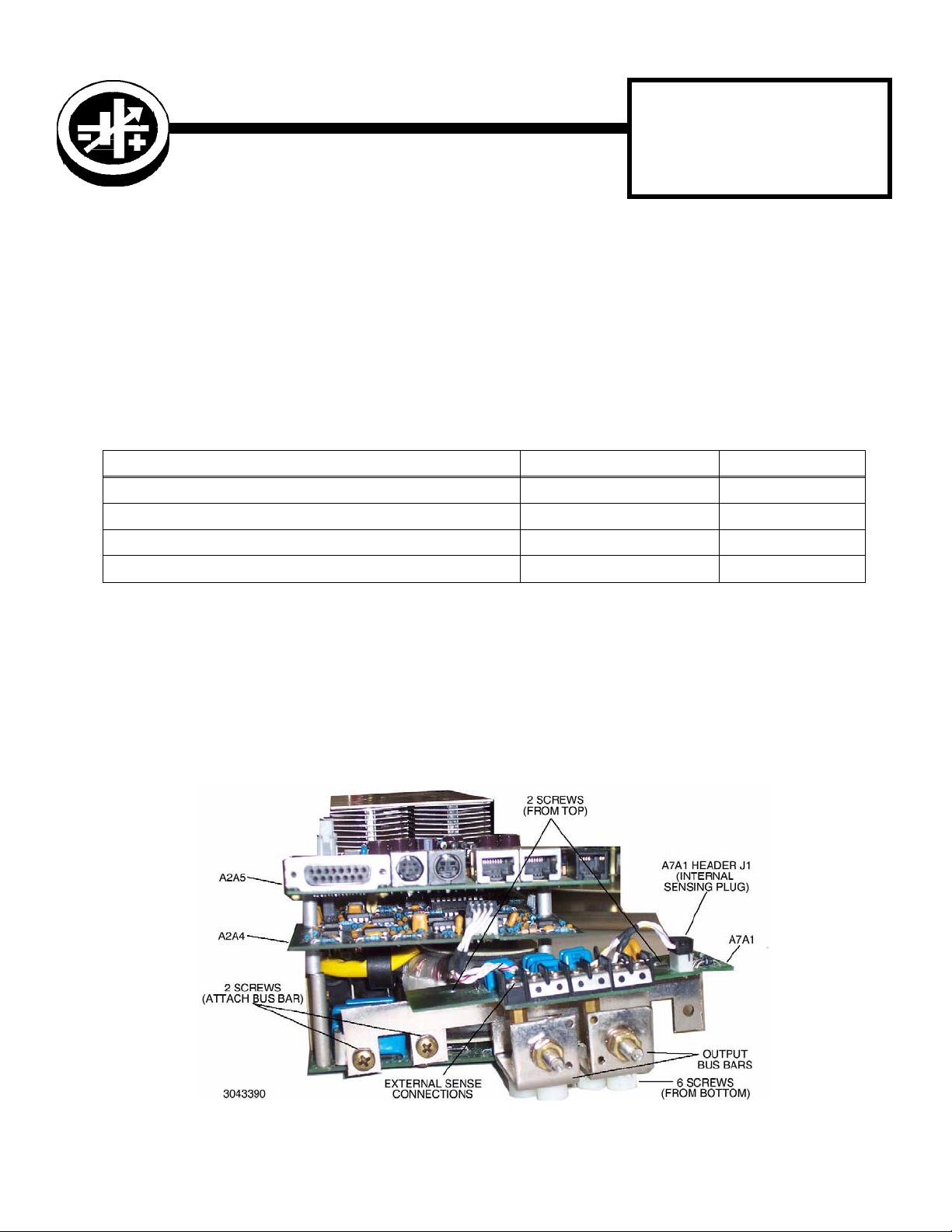
3. Disassemble bus bars together with A7A1 board by removing two screws from top and six screws from bottom
(see Figure 1).
4. Use two screws to attach bus bars with A7A1 to A2 assembly (see Figure 1) and connect the internal sensing
cable to header J1 of A7A1.
FIGURE 1. BUS BAR REMOVAL, REASSEMBLY
KEPCO, INC. " 131-38 SANFORD AVENUE " FLUSHING, NY. 11355 U.S.A. " TEL (718) 461-7000 " FAX (718) 767-1102
http://www.kepcopower.com " email: hq@kepcopower.com
©2008, KEPCO, INC 1
Data subject to change without notice 228-1669
Page 2
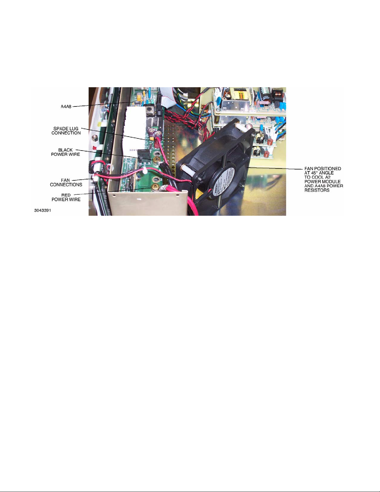
5. Position fan A2B1 within chassis at 45° angle to cool A2 heatsink assembly which has been removed from the
chassis (see Figure 2) as well as the power resistors on A4A8. Air direction must be towards A2.
6. Connect A2 (output module) power wires: black to A4A8J2M and red to A4A8J4M. Connect the wire from A2
terminated in a spade lug to A4A8J5 (see Figure 2).
FIGURE 2. POWER AND FAN CONNECTIONS
NOTE: For debugging purposes, instead of supplying the A2 module with internal d-c input power, an external DC
supply (10V/5A d-c minimum) can be used instead. Disconnect red power wire from A4A8J4M and connect to +output of external DC supply. Then connect – output of DC supply to A4A8J2M.
7. Reinstall ribbon cable from A6A1 to A1 connector A1J2.
8. If troubleshooting requires access to A2A4 proceed to step 9. Otherwise, install A2A4/A2A5 stack on A2A1 following the reassembly notes from the applicable BOP 1000W Service Manual.
a. Refer to Figure 3 and connect the cable from A1J1 to J1 header of PCB connector assembly P/N 236-2744
(from Kit).
b. Install ribbon cable P/N 118-1217 from J2 header of PCB connector assembly P/N 2362744 (from Kit) to
A2A5J5.
9. Separate A2A4/A2A5 stack. Then install A2A4 on A2A1 following the reassembly notes from the applicable
BOP 1000W Service Manual.
a. Refer to Figure 4 and connect the cable from A1J1 to J1 header of PCB connector assembly 2362750
(from Kit).
b. Install pins of A2A5P5 into J2 socket of PCB connector assembly 236-2750 (from Kit).
c. Install ribbon cable P/N 118-1217 from A2A5J5 to J1 header of PCB connector assembly 2362744 (from
Kit).
d. Install pins of J1 header of PCB connector assembly 236-2744 (from Kit) into J5 socket of A2A4.
KEPCO, INC. " 131-38 SANFORD AVENUE " FLUSHING, NY. 11355 U.S.A. " TEL (718) 461-7000 " FAX (718) 767-1102
http://www.kepcopower.com " email: hq@kepcopower.com
2 228-1669 110708
Page 3

FIGURE 3. ACCESS TO A2A5, COMPONENT LOCATIONS
FIGURE 4. ACCESS TO A2A4 AND A2A5, COMPONENT LOCATIONS
KEPCO, INC. " 131-38 SANFORD AVENUE " FLUSHING, NY. 11355 U.S.A. " TEL (718) 461-7000 " FAX (718) 767-1102
110708 228-1669 3
http://www.kepcopower.com " email: hq@kepcopower.com
Page 4

3. TROUBLESHOOTING
This Kit is intended only for testing and debugging of power module assembly A2. Do not operate A2 module at
full power for more than five minutes. Do not perform final calibration of the unit while in the test configuration.
WARNING: Troubleshooting must only be done by properly-trained AUTHORIZED SERVICE PERSON-
NEL. Dangerous and lethal potentials are present, both within this power supply, and at the
output! Perform all required connections with the power supply disconnected from a-c
source power. Never touch external connections while the power supply is on.
Each of the two PCB connector assemblies (236-2750 and 236-2744) includes jumpers (JP1 through JP50) which
are installed in series between the pins of J1 and J2. These jumpers can be removed to interrupt signals and/or
modify signal levels by adding external signals between A1 and A2 as needed for troubleshooting.
4. REASSEMBLY INSTRUCTIONS
1. Turn off power to BOP and all test equipment.
2. Disconnect a-c source power to BOP and all test equipment and disconnect test equipment from BOP.
3. Disconnect and remove ribbon cable P/N 118-1217, connector assembly P/N 236-2750 and (if used) connector assembly P/N 236-2744. Restore all jumpers removed from the two connector assemblies
4. If separated, reinstall A2A4 on A2A5.
5. Refer to Figure 1 and disconnect the internal sense connections and remove two screws to detach bus bar
assembly from A2 assembly. Then install the bus bar with A7A1 on the chassis, using two screws from the top
and six screws from the bottom.
6. Disconnect fan wires.
7. Disconnect A2 (output module) power wires: black from A4A8J2M and red from A4A8J4M. Disconnect the
wire from A2 terminated in a spade lug from A4A8J5 (see Figure 2).
8. Following the reassembly notes in the applicable BOP 1000 Watt Service Manual and using the proper hardware removed during disassembly, reassemble the A2 assembly by attaching the fan and installing the
shroud. Then install the A2 assembly with the shroud on the BOP chassis, and reinstall A1. Restore all connections.
KEPCO, INC. " 131-38 SANFORD AVENUE " FLUSHING, NY. 11355 U.S.A. " TEL (718) 461-7000 " FAX (718) 767-1102
4 228-1669 110708
http://www.kepcopower.com " email: hq@kepcopower.com
 Loading...