

Page 1
INSTRUCTION MANUAL
KEPCO
An ISO 9001 Company.
KIT
BIT 4886
FIRMWARE UPGRADE
1. DESCRIPTION
The Kepco KIT Model 219-0523 contains the firmware upgrade PROM to be installed in BIT 4886 Interface
Cards that have been previously installed in Kepco’s BOP 100-4D-4886 power supply. This firmware
upgrade allows the BOP 100-4D to be programmed to ±104V d-c.
This instruction sheet provides procedures for installing the new PROM, initializing the BIT 4886 card, and
updating the BIT 4886 manual with new information needed for calibrating the BOP power supply.
2. INSTALLATION OF UPGRADE PROM
A. MATERIAL REQUIRED (SEE TABLE 1.)
TABLE 1. MATERIAL REQUIRED
MATERIAL LOCATION
PROM Not Supplied
Extractor Provided in this Kit
ESD (Electrostatic Discharge) wrist strap. Not Supplied
Phillips Screw Driver Not Supplied
Sealant, Kepco P/N 201-0002
(Glyptol P/N 7526P, 7625R or 7625G or equivalent)
Microsoft Windows-based computer with National Instruments VISA software installed Not Supplied
Digital Voltmeter (capable of measuring 100.0005V
(Keithly 2010 multimeter or equivalent
219-0523
Not Supplied
Not Supplied
QUANTITY
4
1
N/A
N/A
N/A
N/A
N/A
B. UPGRADE PROCEDURE
1. Remove a-c power to BOP by disconnecting line cord.
CAUTION: Take care not to damage ground strap connected to cover when removing cover. Ground
strap may be removed for convenience by removing attaching nut.
2. Remove BOP cover by removing 11 screws: (five from each side and one from the top (see Figure 1, Detail A).
3. Remove the BIT 4886 Interface card from the BOP as follows (See Figure 1):
NOTE:Numbers in circles of Figure 1 refer to numbered steps below:
Step 1. Unplug 3 pin Connector from Transformer at BIT 4886 Card, Location #3.
Step 2. Unplug Cable #2 (5-position connectors) from the BIT 4886 Interface Card.
Step 3. Unplug Cable #1 (18-position connectors) from the BIT 4886 Interface Card.
KEPCO, INC. " 131-38 SANFORD AVENUE " FLUSHING, NY. 11352 U.S.A. " TEL (718) 461-7000 " FAX (718) 767-1102
http://www.kepcopower.com " email: hq@kepcopower.com
©2007, KEPCO, INC 1
Data subject to change without notice 228-1620
Page 2
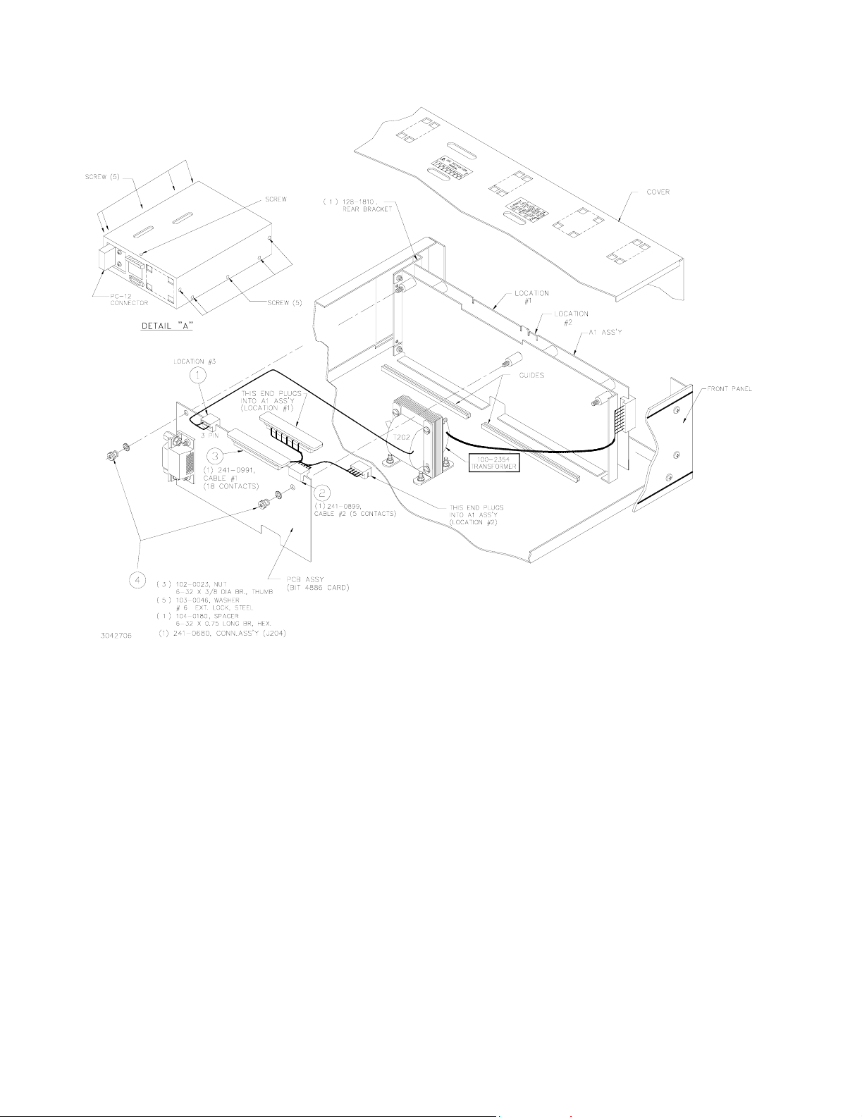
Step 4. Remove the knurled nuts and lockwashers securing the BIT 4886 Card to hex spacers and
remove BIT 4886 Card by sliding to front of BOP, then rotating away from A1.
FIGURE 1. BIT CARD REMOVAL
4. A brown IC socket located towards the rear of the unit contains the PROM. Locate the small depression
or notch in the PROM as shown in Figure 2. This is pin 1 of the PROM.
CAUTION: FAILURE TO USE AN ESD WRIST STRAP MAY DAMAGE THE PROM!
5. Connect the wrist strap to the chassis of the BOP. Place the strap on your wrist as indicated by the
instructions for the wrist strap.
6. Touch the IC tube to the chassis of the BOP. Open one end.
7. Use the extractor and insert the hook, first into one slot and then the other, and gently pry out the PROM.
Place the PROM in the tube and close the tube.
KEPCO, INC. " 131-38 SANFORD AVENUE " FLUSHING, NY. 11352 U.S.A. " TEL (718) 461-7000 " FAX (718) 767-1102
2 228-1620 032807
http://www.kepcopower.com " email: hq@kepcopower.com
Page 3

FIGURE 2. PROM LOCATION
8. Open the other end of the IC tube and remove the replacement PROM from the tube.
9. Insert the PROM into the socket, insuring pin one is as shown in Figure 2.
10. Reclose the IC tube. Remove wrist strap and disconnect it from the BOP.
11. Reinstall the BIT 4886 Card in the BOP by reversing removal (Section. 2.B.3, steps 4 through 1). If removed
earlier, secure ground strap using nut, then Install cover using 11 screws (five at each side, one at top).
12. On the label at the rear of the BOP, after the revision number (XX-Y) mark “A” (XX-YA).
13. Reconnect power cord and turn on the BOP. Verify the unit beeps and initializes normally.
14. Initialize the BIT 4886 card per Section 3.
15. Calibrate the BOP power supply using the revised procedure found in Section 4.
3. INITIALIZATION OF THE BIT 4886 CARD
The initialization procedure uses the “soft” front panel which is part of the CVI driver for the BIT 4886 which can be
downloaded from the Kepco website at: www.kepcopower.com/all_bop.zip.
1. Unzip the files and doubleclick on setup.exe to install the driver. The bit_mdac folder will be added to the Start
- Programs folder. Doubleclick bit_mdac.exe to run the program, and refer to the visamdac.pdf in the bit_mdac
folder for details about using the soft front panel.
2. Connect GPIB cable from the rear of the BOP to a Microsoft Windows-based computer with National Instruments VISA software installed to BIT 4886 card and verify that BOP has standard PC-12 connector installed
(Figure 1).
3. Install the VISA driver per the text file included with the driver. At the Start-up screen (Figure 3) set the correct
GPIB Address and click CONNECT. Upon successful initialization the initialization window closes and the
Power Supply Type field of the Start-up window (Figure 3) shows BIT 4886. Click Continue.
4. Refer to Figure 4 and enter the following information:
• Select Model: BOP 100-4.
• Serial Number: Enter serial number found on the rear nameplate of BOP power supply.
• Option Number: Enter 26810
KEPCO, INC. " 131-38 SANFORD AVENUE " FLUSHING, NY. 11352 U.S.A. " TEL (718) 461-7000 " FAX (718) 767-1102
032807 228-1620 3
http://www.kepcopower.com " email: hq@kepcopower.com
Page 4

• Press the Initialize Card button
NOTE: If initialization fails and an error message is displayed, repeat step 3, making sure that the
proper information is entered, and the new PROM was installed
FIGURE 3. VISA DRIVER START-UP. FIGURE 4. BIT 4886 CARD INITIALIZATION
USING VISA DRIVER
5. After initialization, proceed to revised PAR. 3.3 to calibrate the upgraded unit.
4. BIT 4886 INSTRUCTION MANUAL CHANGES
A. ADD THE FOLLOWING INFORMATION TO TABLE 3-1.
TABLE 3-1. CALIBRATION MEASUREMENTS AND TOLERANCES - VOLTAGE
VOLTAGE
LIMIT
ADJUST
PAR. 3.3.1
STEP 15
PAR. 3.3.2
STEP 3
+104.0125V
±0.0125V
MODEL
BOP 100-4D-
4886-26810
LOW
RANGE
ZERO
PAR. 3.3.1
STEP 2
PAR. 3.3.2
STEP 4
0V
±0.001V0V±0.001V
VOLT
ZERO
PAR. 3.3.1
STEP 3
PAR. 3.3.2
STEP 5
MAX
OUTPUT
PAR. 3.3.1
STEPS 4, 5
N/A
104V
HIGH
RANGE
ACCURACY
PAR. 3.3.1
STEPS 6, 8
PAR. 3.3.2
STEPS 6, 7
104.0075V (MAX)
-104.0075V (MIN)
±0.0075
LOW
RANGE
ACCURACY
PAR. 3.3.1
STEPS 11, 13
PAR. 3.3.2
STEPS 8, 9
26.003V (MAX)
-26.003V (MIN)
±0.002
LOW
RANGE
NOMINAL
PAR. 3.3.1
STEP 10
N/A
26V
KEPCO, INC. " 131-38 SANFORD AVENUE " FLUSHING, NY. 11352 U.S.A. " TEL (718) 461-7000 " FAX (718) 767-1102
http://www.kepcopower.com " email: hq@kepcopower.com
4 228-1620 032807
 Loading...