Kenyon 436, 213 User Manual

KENYON
INSTALLATION &
USER’S GUIDE
for
Models 213 & 436
Alcohol/Electric Combination Stove
KENYON
P.O. Box 925 |
|
|
#8 Heritage Park Road |
Revision 07.20.05 |
|
Clinton, CT 06413 USA |
||
Phone: |
(860) 664-4906 |
Part # 141358 |
Fax: |
(860) 664-4907 |
\Mrpserver\KENYON ENGINEERING\MANUALS\NP Alcohol\213 MANUALS\213 MANUAL |

INTRODUCTION
Thank you for purchasing a KENYON Alcohol/Electric combination stove. The operation instructions that follow are for the models 213 (single burner) and 436 (double burner) alcohol/electric combination stoves. These units feature counter-top mounting, self-priming / self pressurized alcohol burners. The electric portion of the stove operates on 120 VAC (or 240 VAC depending on KENYON Model #).
KENYON marine stoves have been engineered exclusively for the marine environment. Design considerations and materials were dictated by the requirement for safety, reliability, long life, low maintenance, and operation in a salt atmosphere.
IMPORTANT :
PLEASE READ THESE INSTRUCTIONS COMPLETELY
!BEFORE INSTALLATION AND OPERATION OF THE APPLIANCE
DO NOT DISCARD THIS MANUAL. KEEP THIS MANUAL AND
INSTRUCTIONS FOR FUTURE REFERENCE
UNPACKING YOUR KENYON STOVE
Carefully unpack your KENYON Stove from its shipping container. Do not discard the shipping carton or protective foam. It may be useful if your unit ever needs to be serviced.
Verify and Identify Package Contents. The following items should be included in the carton:
1- Alcohol/Electric Stove
1- Fill Bottle
1- Installation and User’s Guide
If any of these items are missing, please contact KENYON Customer Service at (860) 664-4906 or via e-mail: customercare@kenyonappliances.com
VERIFY THE PROPER ELECTRICAL REQUIREMENTS
The table on the following page displays the minimum electrical requirements for each model stove:
The electric supply must be from an individual grounded circuit that is protected by a double pole simultaneous trip circuit breaker rated per the specifications for the various models as shown in the table on the following page.
!Warning: If the electric power supply provided does not meet the product specifications, call a licensed electrician before proceeding with installation.
2

KENYON |
Stove Description |
|
Voltage AC |
Rated Wattage |
Suggested Wire Size Based On Wire |
||||
Model # |
|
|
|
|
(W) & Amps (A) |
Run Length - d (feet) One Way |
|||
|
|
|
|
|
|
|
|
|
|
B61044 |
213 |
A/E w/ Black |
120 |
Volts - 60 Hz |
1100 |
W / 10 A |
d < 35 |
feet : 14 AWG |
|
|
Glass Lid |
|
|
|
|
|
35 < d < 80 |
feet: 12 AWG |
|
B61045 |
213 |
A/E w/ Black |
240 |
Volts - 50/60 Hz |
1100 |
W / 5 A |
d < 125 feet: 14 AWG |
||
|
Glass Lid |
|
|
|
|
|
|
|
|
B61046 |
213 |
A/E w/ White |
120 |
Volts - 60 Hz |
1100 |
W / 10 |
A |
d < 35 |
feet : 14 AWG |
|
Glass Lid |
|
|
|
|
|
35 < d < 80 |
feet: 12 AWG |
|
B61047 |
213 |
A/E w/ White |
240 |
Volts - 50/60 Hz |
1100 |
W / 5 |
A |
d < 125 feet: 14 AWG |
|
|
Glass Lid |
|
|
|
|
|
|
|
|
B61048 |
436 |
A/E w/ Black |
120 |
Volts – 60 Hz |
2200 |
W / 20 |
A |
d < 20 feet: 14 AWG |
|
|
Glass Lid |
|
|
|
|
|
20 < d < 45 feet: 12 AWG |
||
|
|
|
|
|
|
|
|
45 < d < 70 feet: 10 AWG |
|
B61049 |
436 |
A/E w/ Black |
240 |
Volts - 50/60 Hz |
2200 |
W / 10 |
A |
d < 90 feet: 14 AWG |
|
|
Glass Lid |
|
|
|
|
|
|
|
|
INSTALLATION INSTRUCTIONS
NOTE: Installation should comply with ABYC standard A-3, “Recommended Practices and Standards Covering Galley Stoves,” and/or the “Fire Protection Standards for Motorcraft” NFPA #302.
MOUNTING THE ALCOHOL COOKTOP
LOCATING THE COOK TOP AWAY FROM FLAMMABLE MATERIALS
Before you cut your countertop: Make certain the Cook Top will be far enough from flammable materials!
!CAUTION
Do not cut the opening in your countertop until you ensure that there will be adequate horizontal and vertical clearances from the Cook Top to the nearest flammable materialsfabric, plastic, wood- (except the countertop itself).
Minimum Distances are:
40cm (16”) Horizontally 1M (39”) Vertically
It is the installer’s and/or purchaser’s responsibility to ensure that the Cook Top is installed in a location such that a fire hazard is not created.
IN EUROPE:
Contact the authorities appointed by the government in each separate country
IN USA:
Contact ABYC, 3069 Solomons Island Road, Edgewater Maryland 21037-1416 tel (410) 956 1050 fax (410) 956 2737 internet abycinc@aol.com
3

LOCATION & COUNTER-TOP PREPARATION
The stove must be located in an area with adequate ventilation for occupants’ safety and efficient stove operation. It should be installed with adequate clearances between the stove top and all surrounding surfaces (i.e. curtains, cabinets, etc) in order to minimize heat transfer to these surfaces. Also fire resistant materials should be attached to any surrounding surfaces, especially overhead.
Once a location for the stove has been chosen, it is important to check clearances underneath the counter for the bottom portion of the stove and its moving parts. The stove extends about 6 inches (152 mm) below the countertop. If drawers or cabinets are located under the stove, a rigid barrier must be installed to prevent combustible items, (i.e. rags, paper, etc.) from coming in contact with the hot stove. The barrier must be ventilated.
Adequate ventilation of the space below the stove must be provided to ensure proper operation of the stove. Heat transferred from the cook top bottom pan during operation will overheat an improperly ventilated area.
FAILURE TO PROVIDE PROPER CLEARANCES AND VENTILATION MAY RESULT IN A FIRE HAZARD.
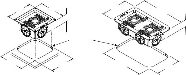
General dimensions for each model stove are shown below:
213 Model |
|
|
436 Model |
12 3/4" |
12 3/4" |
13 1/2" |
22 1/2" |
|
5 3/4" |
3" Radius |
5 3/4" |
|
||
|
|
12 1/4" |
12 1/4" |
21 3/4" |
12 3/4"
Note: A 3" radius is required
INSTALLATION
Once the cutout has been prepared as shown on page 3, pre-fit the stove into the cutout to mark drill locations. Tilt and insert the front portion of the stove first. Care should be exercised so as not to damage or bend any moving parts. Next, lower the stove into the cut out. Using a pencil mark the location of mounting holes onto the counter. Carefully remove the stove from the cutout. Using a 1/8" drill and the pencil marks as a guide, drill four (4) mounting holes. Replace the stove into the counter. Mount the stove in place by using (4) #8 x 5/8" oval head stainless steel wood screws(not supplied).
Electrical Connection
It is recommended that the supply conductors be protected with a double pole simultaneous trip circuit breaker per the specifications for the various models and voltages as shown in the Electrical Requirements Table on page 3. Use SO rubber-insulated cable to connect the boat shore power electrical circuit to the terminal board in back of the stove.
NOTE: Only qualified installers should connect this appliance to the electrical service.
4
 Loading...