

Page 1

Kenworth Clean Power™ System
Operator’s Manual
Y53-1024 12/06
English Page 5
French Page x
Spanish Page x
Page 2
Y53-1024 12/06 Kenworth
- 2 -
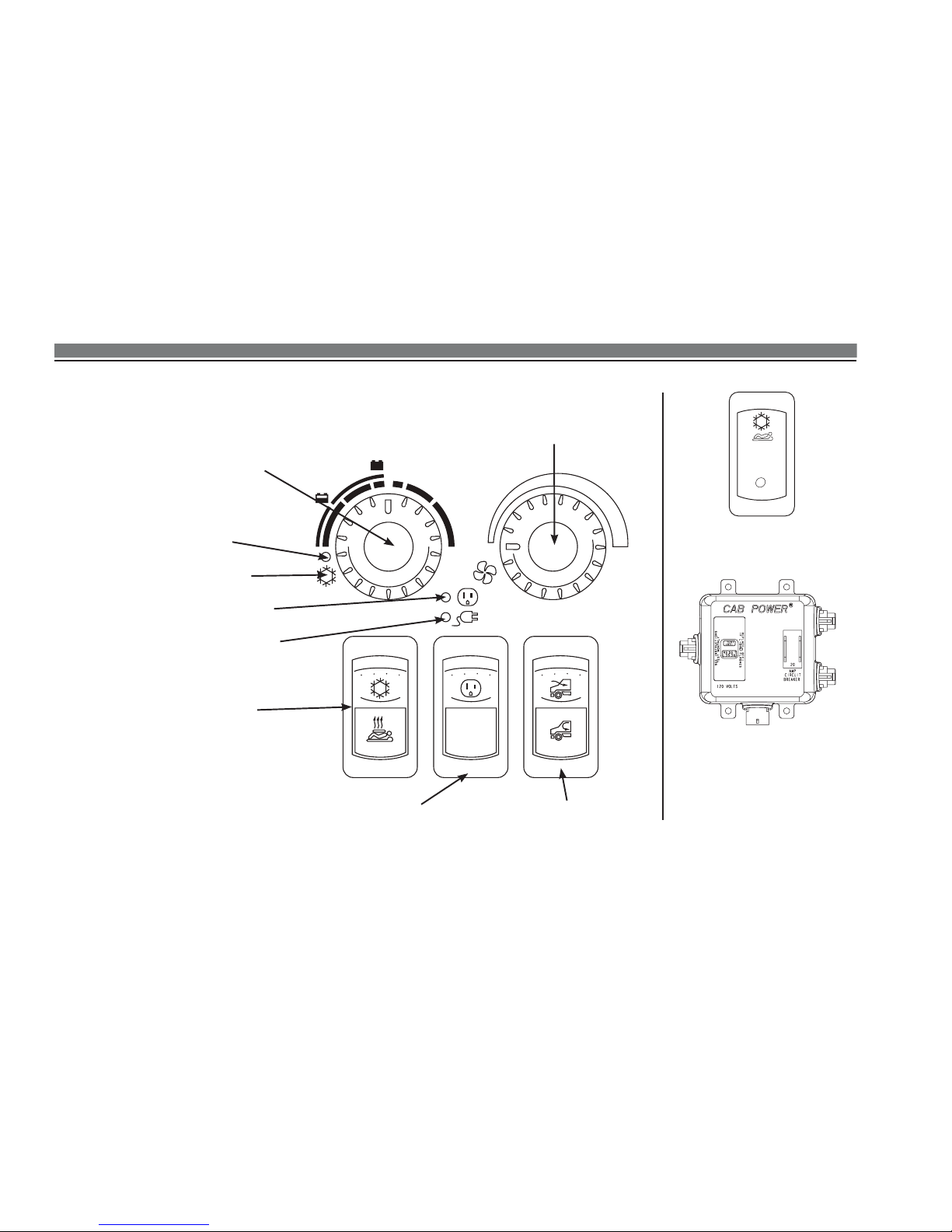
NORMAL
OFF/RESET
OFF
Inverter/Charger Lamp
Shore Power Lamp
(120-Volt AC)
Air Conditioning/Heating
Switch
Inverter/Charger
Switch
Air Conditioner
Pump Lamp
Fan Control Dial
Sleeper Fresh/Recirculation Air
Switch
CHARGE
Charge/Enable Switch
(located on dash)
Protection Unit
(Circuit Breaker/GFCI)
(located in driver’s side tool
box)
Sleeper Control Panel
Temperature Control Dial
Green Snowflake
Page 3
Kenworth Y53-1024 12/06
- 3 -
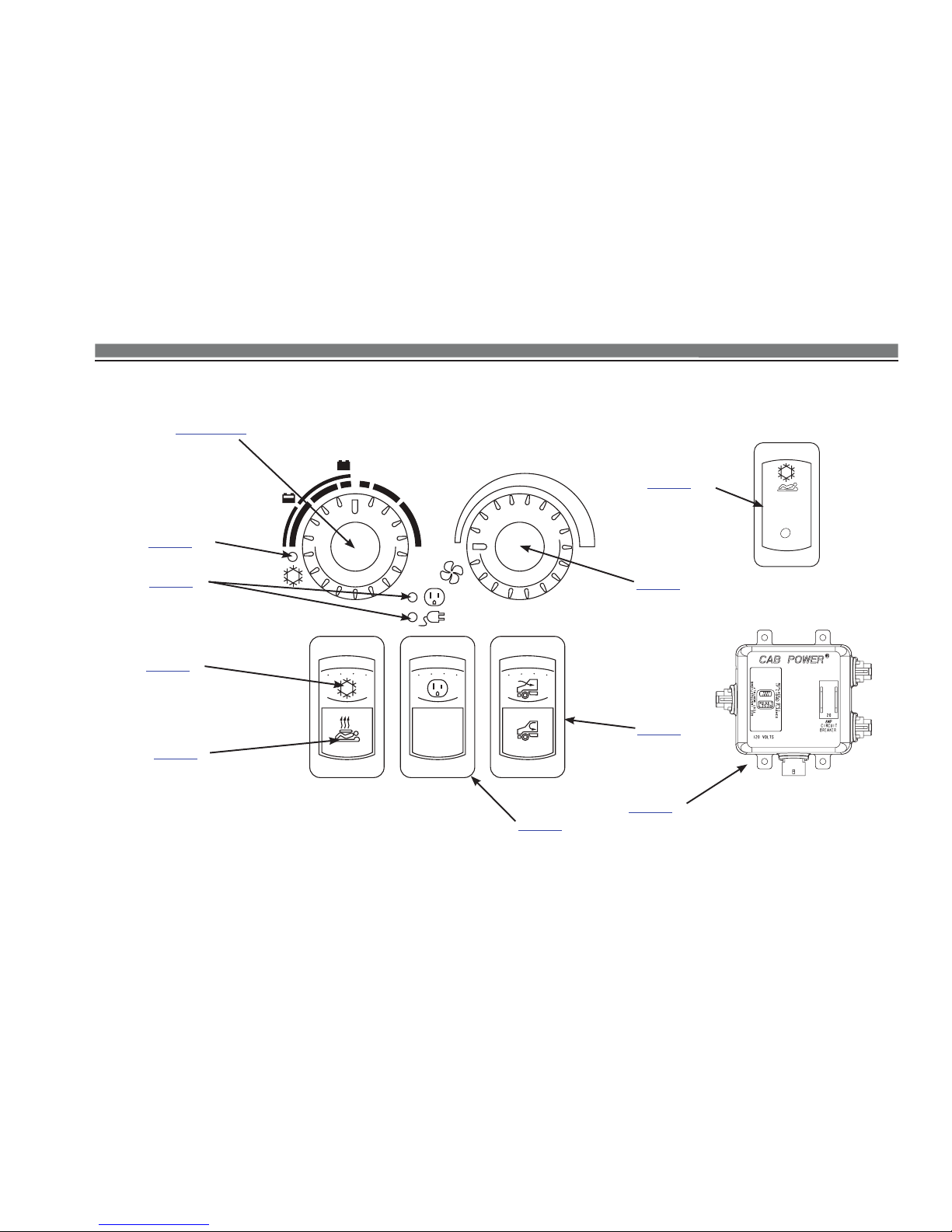
NORMAL
OFF/RESET
OFF
Page 19
Page 26
Page 24
Page 19
Page 28
Page 25 & 27
Page 28
CHARGE
Page 32
Page 22
Page 27
Page 4

Y53-1024 12/06 Kenworth
- 4 -
contents
Jump-Start Procedure ................................................. 9
Diagram ...................................................................................10
Charging using Shore Power ...................................................12
Charging using Battery Charger ..............................................13
12-Volt DC System ..................................................... 14
Main Batteries ..........................................................................15
Starter Batteries ......................................................................16
Interior Lighting ........................................................................ 16
Electrical System Monitoring ...................................................17
Low Voltage Disconnect ...........................................................17
120-Volt AC System ................................................... 18
Shore Power and Inverter ........................................................18
Inverter/Charger Switch ........................................................... 19
Inverter/Charger & Shore Power Lamps ..................................19
Inverter/Charger Indicator Chart .............................................. 20
Protection Unit .........................................................................22
120-Volt AC Outlets .................................................................23
Introduction
The Kenworth Clean Power System .......................... 5
Location of Components ............................................................6
Safety Signals ............................................................................7
Electric Power System
Troubleshooting
Troubleshooting ......................................................... 34
Heating and Air Conditioning System
Using the Heater ........................................................ 24
Air Conditioning/Heating Switch ..............................................24
Temperature Control Dial .........................................................25
Fuel-Fired Heater ....................................................................25
Using the Air Conditioner ......................................... 26
Air Conditioning/Heating Switch ..............................................26
Temperature Control Dial .........................................................27
Air Conditioning Pump ON Lamp ............................................27
Fan Control Dial .......................................................................28
Fresh/Recirculation Air Switch .................................................28
Cooling Vents ..........................................................................29
Storage Cooler ........................................................................30
Air Conditioning Charge Unit ...................................................31
Charge Enable Switch .............................................................32
System Operation to Ensure Maximum
Cooling Efficiency ....................................................................33
Page 5

Kenworth Y53-1024 12/06
- 5 -
Introduction
INTRODUCTION
The Kenworth Clean Power System
The Kenworth Clean Power System is a battery-powered sleeper climate
control system with the capability to provide engine-off heating and cooling, plus 120-Volt AC accessory power to drivers for up to 10 hours. To
recharge the cooling and electrical capacity, the truck must be driven or
connected to shore power.
The Kenworth Clean Power System sleeper heating and air conditioning
system is an independent system from the cab heating and air conditioning
system. Both the controls and the heat and cooling sources are different.
Kenworth Clean Power System features include:
Compliance with all state and federal anti-idling regulations.
Engine-off sleeper heating, cooling, and 120-Volt AC power.
No engine noise or vibration.
Improved fuel economy.
•
•
•
•
This Operator’s Manual contains useful information for the safe and efficient operation of your Kenworth Clean Power System.
All information contained in this manual is based on the latest production
information available at the time of publication. Kenworth Truck Company
reserves the right to make changes at any time without notice.
Page 6
Y53-1024 12/06 Kenworth
- 6 -
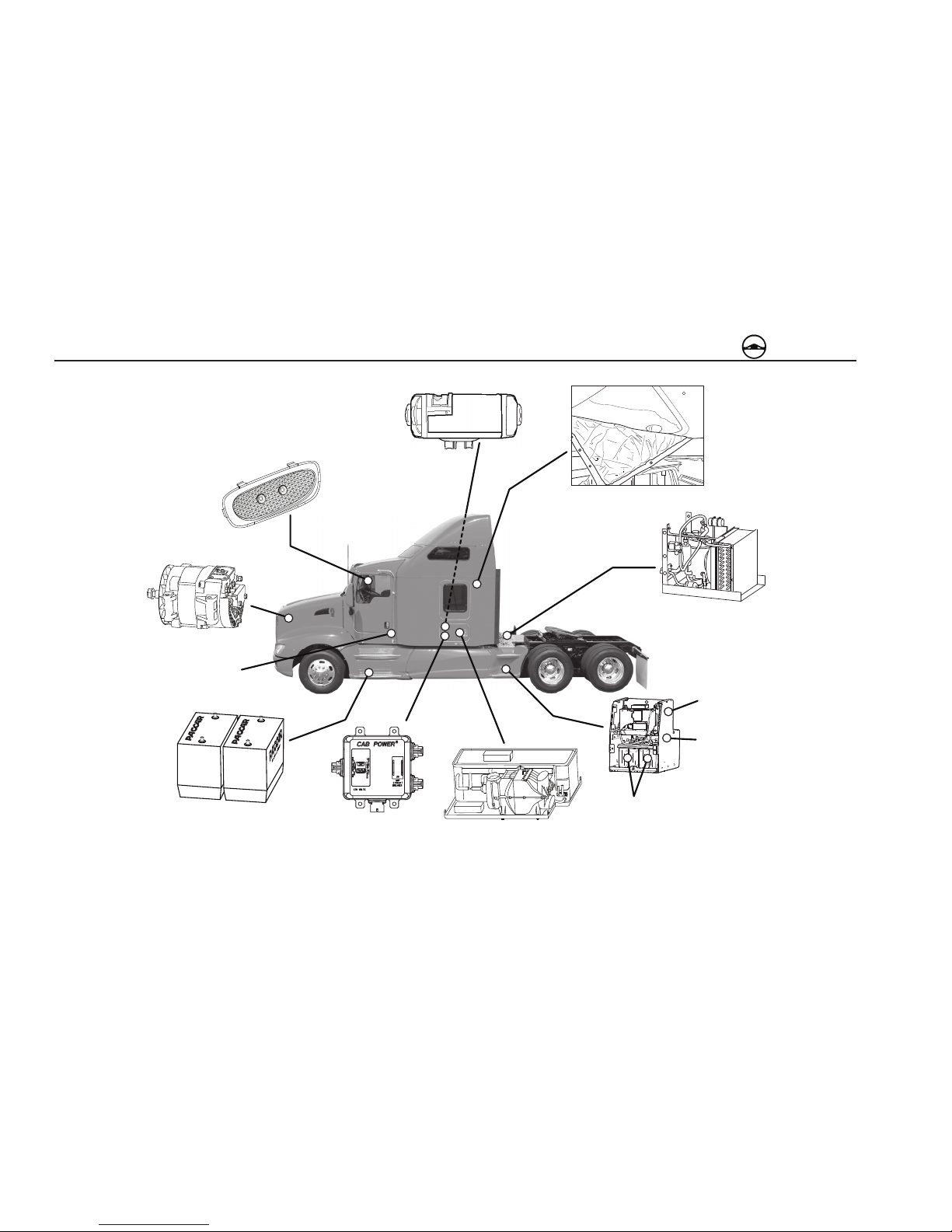
Introduction
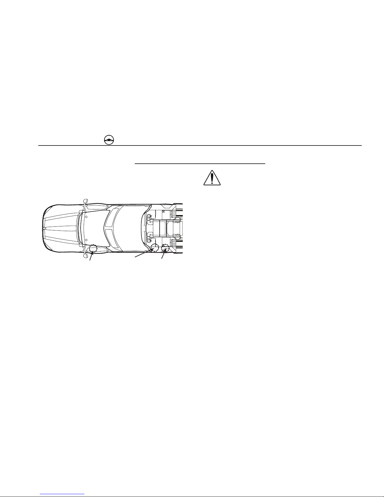
High Output Alternator
Starter Batteries
Storage Cooler (under lower bunk)
Main Batteries
Air Conditioning
Charge Unit
Enhanced Insulation
Fuel-Fired Heater
(in passenger’s side
tool box)
LED Lighting
Protection Unit
(in driver’s side tool box)
Location of Components
Starter Battery Disconnect
Switch (cab fl oor)
Shore Power
(120-Volt AC)
Connector
Main Battery
Disconnect Switch
Page 7
Kenworth Y53-1024 12/06
- 7 -
Introduction
Safety Signals
A number of alerting messages are in this manual. Please read and follow
them. They are there for your protection and information. These messages
can help you avoid injury to yourself and your passengers, and help prevent
costly damage to the vehicle.
Key symbols and “signal words” are used to indicate what kind of message
is going to follow. Pay special attention to instructions prefaced by symbols
and signal words “WARNING,” “CAUTION,” or “NOTE.” Please do not ignore
any of these alerts.
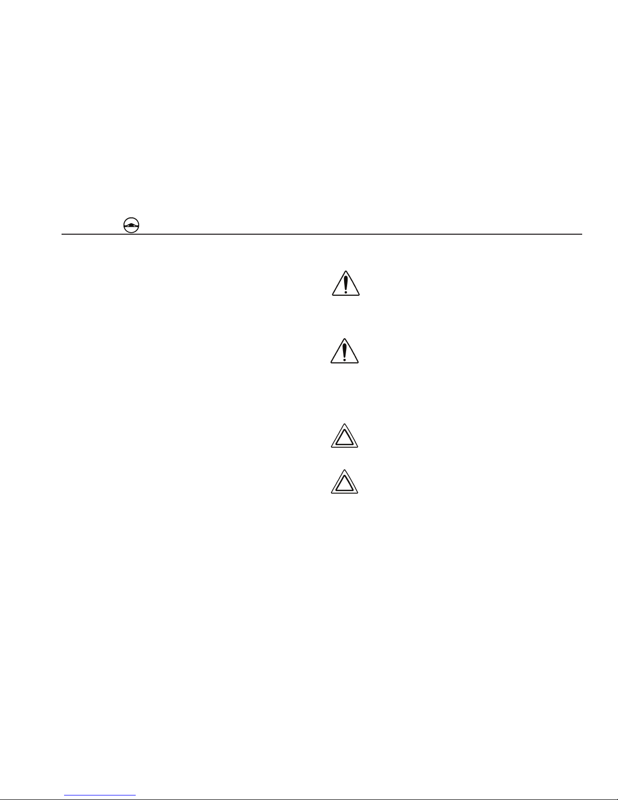
WARNING
When you see this symbol and word, the message that follows is
especially vital. This signals something that can cause injury or
even death. This message will tell you what the hazard is, what
can happen if you don’t heed the warning, and how to avoid it.
Example:
WARNING! Do not carry additional fuel containers in your vehicle. Fuel containers, either full
or empty, may leak, explode, and cause or feed
a fire. Do not carry extra fuel containers, even
empty ones are dangerous.
CAUTION
This symbol and word signals something that could damage your
vehicle.
Example:
CAUTION: Continuing to operate your vehicle
with insufficient oil pressure will cause serious
engine damage.
Page 8
Y53-1024 12/06 Kenworth
- 8 -
Introduction
NOTE
Gives you information we feel you would like to have. It could have to do
with care of your vehicle or with driving more efficiently.
Example:
NOTE: Pumping the accelerator will not assist in
starting the engine.
Please take the time to read these messages when
you see them, and remember:
WARNING!
Something that could cause an injury or even death.
CAUTION:
Something that could cause damage to your vehicle.
NOTE:
Useful information.
Page 9
Kenworth Y53-1024 12/06
- 9 -
Electric Power System
Charging instructions for the Kenworth Clean Power System is as follows:
ELECTRIC POWER SYSTEM
WARNING! Do not attempt to jumpstart the vehicle. The electrical charging system used for the
Kenworth Clean Power System is different than
normal charging systems. Failure to adhere to
the proper charging procedure could lead to serious injury or vehicle damage. Refer to the charging instructions located on the top of the main
battery box cover or in the Kenworth Clean Power
operator’s manual supplement/service manual.
Do not attempt to jumpstart the vehicle. If you have a battery problem, it is
best to contact an authorized Kenworth repair facility or a reputable towing
service. When you do, inform them of the charging instructions and the
wiring schematic on page 10.
Vehicles equipped with the Kenworth Clean Power System have battery
configurations that are different than traditional vehicles. These vehicles
have two different sets of batteries; the Main Batteries and the Starter Batteries.
Starter Batteries
Charging Terminals
Main Batteries
Charging Instructions
Page 10
Y53-1024 12/06 Kenworth
- 10 -
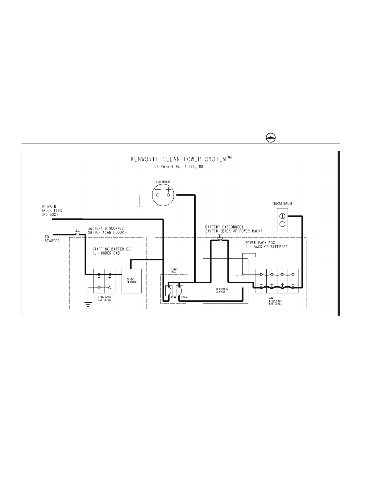
Electric Power System
CHARGING
Page 11

Kenworth Y53-1024 12/06
- 11 -
Electric Power System
The Main Batteries are located behind the sleeper, on the driver’s side.
They power all electrical systems on the vehicle EXCEPT the starter motor.
The Starter Batteries are located below the cab, on the driver’s side, where
the vehicle’s batteries have traditionally been located. They power the
starter motor.
NOTE: The starter relay and other engine controls
rely on the Main Batteries for power; therefore, the
Starter Batteries can be fully charged and the Start
er Motor will not crank if the Main Batteries are not
charged. Do not jump start the Starter Batteries without checking the Main Battery voltage first.
A DC/DC charger, also located below the cab on the driver’s side, serves to
isolate the starting batteries from the main batteries and provides charge to
the starting batteries to maintain them at a minimum of 12-Volt.
NOTE: The DC/DC charger will only be activated
when either the truck is running or the truck is at
tached to a 120-Volt AC electrical supply and the key
is in the IGN position.
1. Check battery voltmeter gauge on dash to ensure main battery voltage
is at least 9.5-Volt.
2. If not, plug into 120-Volt AC electrical supply to charge main batteries or
attach battery charger to charging terminals located in back of sleeper.
3. Once main battery voltage is at least 9.5-Volt, attempt to start the truck.
If truck does not start, ensure that starter battery voltage is at least 12-Volt
(check at starter using voltmeter.)
4. If not, charge the starter batteries with an external battery charger.
5. Once starter battery voltage is at least 12-Volt, attempt to start the truck.
If truck does not star t, the truck should be towed to the nearest authorized
Kenworth dealer.
Refer to the Troubleshooting Section on page 33 for more details.
Page 12

Y53-1024 12/06 Kenworth
- 12 -
Electric Power System
Disconnect Instructions
Prior to servicing the vehicle, disconnect the electrical system as follows:
1. Unplug connection to 120-Volt AC electrical supply.
2. Turn disconnect located at cab floor to OFF position.
3. Turn disconnect located on main battery box (located driver’s side, rear
of sleeper) to OFF position.
NOTE: Do not connect any accessories directly to
the starting batteries. Accessory loads should be
connected to the main batteries only.
Refer to Kenworth Clean Power operator’s manual
supplement/service manual for further details. If you
are uncomfortable with performing the procedures
above, contact the nearest authorized Kenworth
dealer.
Page 13
Kenworth Y53-1024 12/06
- 13 -
Electric Power System
WARNING! Electric Shock Hazard. 120-Volt AC
power present. Only a trained technician should
work on the 120-Volt AC system. Turn all disconnects (both at the cab floor and on the main
battery box located on the driver’s side, back of
sleeper) to the OFF position and unplug the 120Volt AC electrical supply before servicing any
part of the vehicle’s electrical system.
WARNING! An improperly maintained 120-Volt AC
electrical system can cause fires and electrical
shocks that may lead to personal injury or property damage. Regularly inspect 120-Volt AC
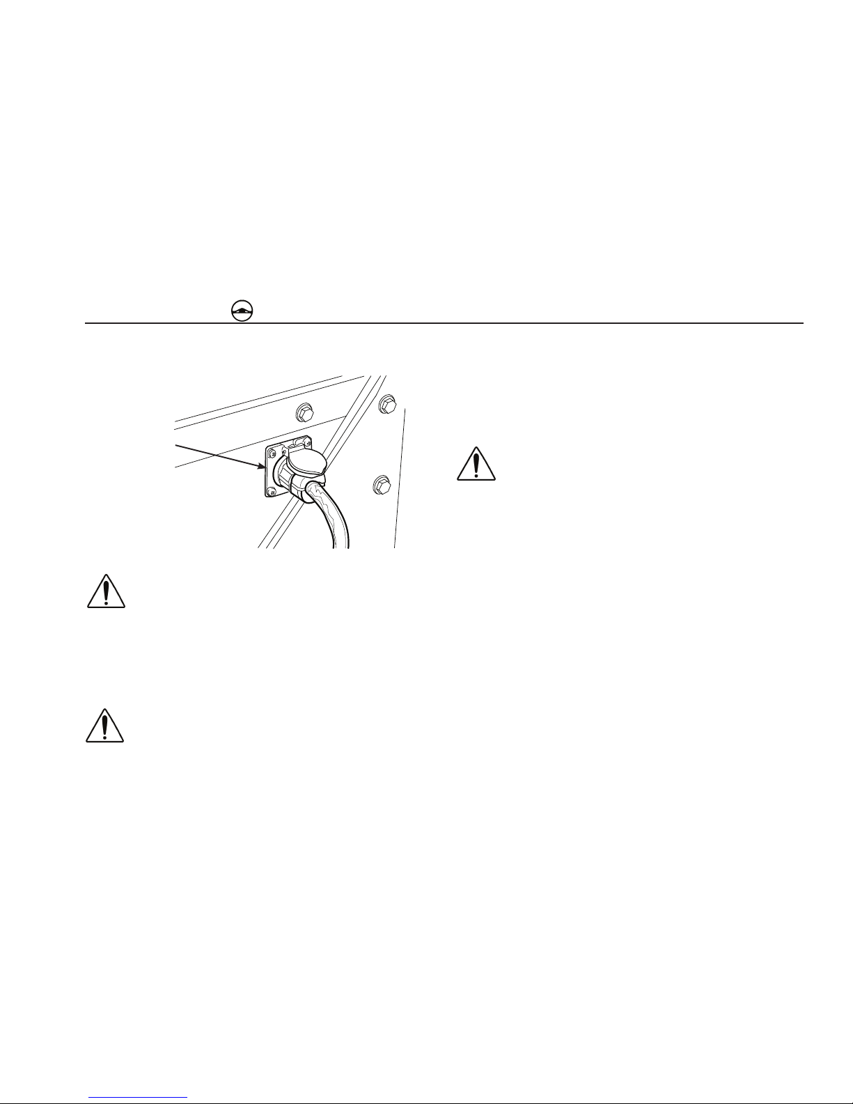
Charging using Shore Power (120-Volt AC Electrical
Supply)
Shore Power
Connection
electrical wiring connectors for damage. Always
use a properly grounded 20 Amp AC extension
cord that is no longer than 25 ft. and a 20 Amp AC
protected power source with a grounding conductor when connecting to a 120-Volt AC electrical supply.
WARNING! The Shore Power electrical system
can cause fires resulting in personal injury and/
or property damage if not properly maintained.
Regularly inspect the Volt AC truck wiring, AC extension cord, plugs, and connectors for damaged
or frayed wiring. Do not use the Shore Power
system if there are any signs of problems. Contact your authorized Kenworth Dealer if you are in
need of repairs or information.
Attach the 120-Volt AC extension cord to a 20 amp protected circuit until system voltage is restored. The Shore Power electrical connection is
located on the rear of the Main Battery Box. Make sure that the Inverter/
Charger Switch is in the ON position and that the circuit breaker on the
Protection Unit box has not been tripped. The Shore Power Lamp on the
Sleeper Control Panel will illuminate green and the Inverter/Charger Lamp
will illuminate orange.
Normal system voltage is 13.5 to 14.6 -Volts. Typically the Main Batteries
must reach at least a 9.5-Volt charge to power the engine controls necessary to start the engine.
Page 14

Y53-1024 12/06 Kenworth
- 14 -
Electric Power System
Charging using Battery Charger
Attach a battery charger to the charging terminals and charge batteries until
system voltage is restored. Refer to “Battery Charging” in the Kenworth
Operator’s Manual for proper battery charging procedures.
Caution: Do not attempt to jumpstart the vehicle.
Terminals are for use with external battery charger only. For charging instructions, see top of
main battery box cover or the kenworth Clean
Power operator’s manual supplement/service
manual.
Positive (+) and negative (-) charging terminals for are located above the
frame rail, behind the sleeper, on the driver’s side of the vehicle.
Negative (-) Charging Terminal
Positive (+) Charging Terminal
Page 15

Kenworth Y53-1024 12/06
- 15 -
Electric Power System
12-Volt DC System
Starter Batteries
Main Batteries
The 12-Volt Direct Current (DC) System consists of Main Batteries, Starter
Batteries, a Low Voltage Disconnect system, gauges for Electrical Monitoring, and special Interior Lighting. Vehicles equipped with the Kenworth
Clean Power System have a unique 12-Volt electrical system. The system
uses a high output alternator and two sets of batteries; the Main Batteries
and the Starter Batteries.
Page 16

Y53-1024 12/06 Kenworth
- 16 -
Electric Power System
The Main Batteries are located on the driver’s side of the vehicle behind the
sleeper compartment. The four Deep Cycle AGM (Gel-Cell) batteries power
all electrical system components on the vehicle EXCEPT the starter motor.
Caution: Do not replace the Deep Cycle AGM (GelCell) batteries with common lead acid batteries.
The Kenworth Clean Power System is designed
to draw to very low voltages which will significantly reduce the life of a lead acid battery. Use
only PACCAR recommended Main Batteries. See
your Kenworth dealer for additional information.
NOTE: Because the Main Batteries power the en
gine controls, you may experience a no-crank condition if the main battery voltage is below 9.5-Volt, even
though the Starter Batteries are fully charged.
Main Batteries
WARNING! Do not cover the batteries with additional insulation or covers or store any items
around the batteries. Additional insulation or
items around the batteries will lead to poor venting which could result in a fire and/or explosion
that may lead to personal injury or equipment
damage.
Main Batteries
Deep-Cycle AGM
(Gel Cell) Batteries
Shore Power Connector
Page 17

Kenworth Y53-1024 12/06
- 17 -
Electric Power System
Starter Batteries
The Starter Batteries (two 1000 Cold Cranking Amp 12-Volt batteries) are
located below the cab on the driver’s side of the vehicle. These batteries
are used only to power the starter motor.
A DC/DC charger is located below the cab on the driver’s side of the vehicle. It serves to isolate the starting batteries from the main batteries and
provides charge to the starting batteries to maintain them at a minimum of
12-Volts.
NOTE: The DC/DC charger will only be activated
when either the truck is running or the truck is at
tached to a 120-Volt AC electrical supply and the key
is in the IGN position.
Low Voltage Disconnect
The electrical system is equipped with a low voltage disconnect feature
that will shut-down all non-essential electrical components if Main Battery
voltage drops below 11.0 -Volt. Three minutes prior to system disconnect an
audible warning in the Sleeper Control Panel will sound to give the operator
time to switch to an alternative power source or reduce loads. To reset the
system the Main Batteries must be charged until a system voltage of 13.2Volts or greater is reached. This can be accomplished by attaching to shore
power, starting the engine, or attaching a battery charger to the charging
terminals. Turning the ignition key to the ON position will not disable the Low
Voltage Disconnect.
Page 18

Y53-1024 12/06 Kenworth
- 18 -
Electric Power System
Electrical System Monitoring
Normal system voltage on vehicles equipped with the
Kenworth Clean Power System is between 13.5 and 14.6 Volts. This is slightly higher than vehicles without the
Kenworth Clean Power System.
All vehicles come equipped with a dash-mounted voltmeter. Some vehicles
may be equipped with an optional ammeter as well.
-150
-75
0
+150
+75
AMPS
A
-
+
VOLTS
18
15
12
9
-
+
300
250
200
150
100
WATER
100
80
60
20
0
OIL
NOTE: These gauges monitor the Main Batteries,
not the Starter Batteries.
An indicator lamp on the face of the voltmeter will illuminate if system voltage reaches 15.0 -Volts. This is considered an over voltage condition. If
this occurs, contact the nearest authorized Kenworth repair facility.
Ammeter
(Optional)
Voltmeter
Page 19

Kenworth Y53-1024 12/06
- 19 -
Electric Power System
Interior Lighting
Your vehicle may be equipped with Light Emitting Diode (LED) interior
lamps. These lamps are more efficient and have a greater life expectancy
than incandescent lamps.
LED light fixtures do not have replaceable bulbs as do incandescent light
fixtures. If an LED light fails the entire fixture may need to be replaced.
Page 20

Y53-1024 12/06 Kenworth
- 20 -
Electric Power System
Shore Power (120-Volt AC System)
WARNING! Electric Shock Hazard. 120-Volt AC
power present. Only a trained technician should
work on the 120-Volt AC system. Turn all disconnects (both at the cab floor and on the main
battery box located on the driver’s side, back of
sleeper) to the OFF position and unplug the 120Volt AC electrical supply before servicing any
part of the vehicle’s electrical system.
The 120-Volt Alternating Current (AC) system consists of a 120-Volt AC
Electrical System connection, Inverter/Charger, Protection Unit, and 120Volt AC outlets in the sleeper.
Shore Power and Inverter
Shore Power Hook Up
WARNING! An improperly maintained 120-Volt
AC electrical system can cause fires and electrical shocks that may lead to personal injury or
property damage. Regularly inspect 120-Volt AC
electrical wiring connectors for damage. Always
use a properly grounded 20 Amp AC extension
cord that is no longer than 25 ft. and a 20 Amp AC
protected power source with a grounding conductor when connecting to a 120-Volt AC electrical supply.
Page 21

Kenworth Y53-1024 12/06
- 21 -
Electric Power System
WARNING! The Shore Power electrical system
can cause fires resulting in personal injury and/
or property damage if not properly maintained.
Regularly inspect the Shore Power truck wiring,
AC extension cord, plugs, and connectors for
damaged or frayed wiring. Do not use the Shore
Power system if there are any signs of problems.
Contact your authorized Kenworth Dealer if you
are in need of repairs or information.
The Kenworth Clean Power System enables you to access 120-Volt AC
power from two different sources. A Shore Power connection allows access
to an outside power source and an electrical inverter system can produce
120-Volt AC from the Main Batteries.
Inverter/Charger Switch
The 120-Volt AC system function is controlled by
the Inverter/Charger Switch located on the Sleeper
Control Panel.
When the top of the switch is pressed, (NORMAL
position) the inverter/charger is on and the green
electrical outlet symbol on the switch will turn on.
This is the normal operating position for the inverter/charger.
When the bottom of the switch is pressed (OFF/RESET position), the inverter/charger will be off and the green electrical outlet
symbol on the switch will turn off. Refer to the Inverter/Charger Indicator
chart on the next two pages for Reset information.
Page 22

Y53-1024 12/06 Kenworth
- 22 -
Electric Power System
LED Status
System Status
Inverter/Charger LED
120VAC Lamp
Inverter/Charge
Switch
120VAC Inverter
Charger
Solid Green OFF ON OFF
ON
OFF
Blinking Green
(0.5 sec ON, 4.5 sec OFF)
OFF
ON OFF Input Low Voltage
OFF
Blinking Green
(0.2 sec ON/OFF, 4.5 sec OFF)
OFF ON OFF Input Low Volatge Warning OFF
Blinking Green
(0.5 sec ON, 4.5 sec OFF)
OFF ON
OFF Input Over Voltage Protection
OFF
Solid Red
OFF ON
OFF
Overload; Short Circuit
Protection; Output Over Voltage
Protection
OFF
Blank
OFF
ON
OFF
Over Temp
OFF
Solid Orange Solid Green ON ON OFF ON
Solid Orange
Solid Green
ON ON
OFF Thermally Derated Charge
Solid Orange
Solid Green
ON
ON OFF
Overload; SCP
Blinking Orange/Red
(4 sec Orange, 1 sec Red)
Solid Green
ON ON
OFF
Low Voltage Charging
Blinking Orange/Red
(0.5 sec Orange, 0.5 sec Red)
Solid Green ON ON
OFF
Low Voltage Timed Charge
Blank
OFF
ON
Battery Disconnect
Blank
OFF
OFF
OFF
Inverter/Charger Indicator Chart
Page 23

Kenworth Y53-1024 12/06
- 23 -
Electric Power System
LED Status
Inverter/Charger LED 120VAC
Remedy
Solid Green Blank Normal inverter/charger operation, no action required.
Blinking Green
(0.5 sec ON, 4.5 sec OFF)
Blank
- Inverter/charger will auto-restart if voltage reaches an acce
p
table level.
- Cycle inverter/charger on/off switch to off/reset and then back on to reset inverter.
1
Blinking Green
Blank
- Inverter/charger will auto-restart if voltage reaches an acceptable level.
(0.2 sec ON/OFF, 4.5 sec OFF)
- Cycle inverter/charger on/off switch to off/reset and then back on to reset inverter.
1
Blinking Green
(0.5 sec ON, 0.5 sec OFF)
Blank
- Inverter/char
g
er will auto-restart if voltage reaches an acce
p
table level.
- Cycle inverter/charger on/off switch to off/reset and then back on to reset inverter.
1
Solid Red Blank
- Cycle inverter/charger on/off switch to off/reset and then back on to reset inverter.
1
Blank
Blank
- Inverter/charger will auto-restart if temperature reaches an acceptable level.
- C
y
cle inverter/charger on/off switch to off/reset and then back on to reset inverter.
1
Solid Orange Solid Green
Normal inverter/charger operation, no action required.
Solid Orange Solid Green
Charging will derate at high temperatures, no action required.
Solid Orange Solid Green
- Inverter/charger will auto-restart if conditions reach an acceptable level.
- C
y
cle inverter/charger on/off switch to off/reset and then back on to reset inverter.
1
Blinking Orange/Red
(4 sec Orange, 1 sec Red)
Solid Green
Low voltage charging operation, allows for charging of batteries as low as 5V, no action
required.
Blinking Orange/Red
(0.5 sec Orange, 0.5 sec Red)
Solid Green
If batteries at a low voltage are not successfully accepting a charge, inverter/charger will turn
off. Cycle inverter/charger on/off switch to off/reset and then back on to reset
inverter/charger.
1,2
Blank
Blank
Turn inverter/charger on/off switch to off/reset. Reconnect batteries to inverter/charger. Turn
inverter/charger on/off switch to on.
Blank
Blank
For inverter/charger function, turn inverter/charger on/off switch to on.
1
If after restarting the inverter/charger the blink code persists, please see your local
Kenworth service dealer.
2
Continuous charging of low voltage batteries is not recommended. If low voltage charging
is unsuccessful after restarting inverter/charger, replace main batteries.
Page 24

Y53-1024 12/06 Kenworth
- 24 -
Electric Power System
Inverter/Charger & Shore Power Lamps
Inverter/Charger Lamp
Shore Power Lamp
The Inverter/Charger and Shore Power Lamps located in the center of the
Sleeper Control Panel will illuminate in an array of colors and configurations
to designate system status. Refer to the Inverter/Charger Indicator chart on
the next page for more information.
Protection Unit
20 Amp
Circuit Breaker
Protection Unit (GFCI)
Protection Unit
Page 25

Kenworth Y53-1024 12/06
- 25 -
Electric Power System
The Protection Unit houses a 20 Amp circuit breaker and a Ground Fault
Circuit Interrupter (GFCI) that provides circuit protection for the 120-Volt AC
system. The Protection Unit is located in the front of the tool box on the
driver’s side of the sleeper.
The circuit breaker is located on the right side of the Protection Unit box. If
the breaker is tripped (circuit open) it can be reset by pressing the top of the
rocker switch to the ON position.
The GFCI is located on the left side of the Protection Unit box. The GFCI
will open (disconnecting the power) if a ground fault is detected on the circuit. The unit can be reset by pressing the RESET button on the top of the
GFCI.
NOTE: Replace GFCI if light on GFCI flashes. If this
is not done, outlets will not be powered.
WARNING! Electrical shock hazard. Use of a
ground-fault circuit-interrupter other than that
supplied with the Protection Unit may fail to operate properly and may lead to personal injury
or equipment damage. Use only the ground-fault
circuit interrupter that is supplied with the Protection Unit.
120-Volt AC Outlets
120-Volt AC Outlets
Two 120-Volt AC duplex style outlets are located in the sleeper compartment, one under the driver’s side lower bunk, the second in the passenger
side closet. They are powered by either a 120-Volt AC electrical supply or
by the Main Batteries through the Inverter.
NOTE: The Inverter has its own low voltage discon
nect system that will shut off power to the two duplex
outlets when the Main Battery voltage gets below 11
-Volts.
Page 26

Y53-1024 12/06 Kenworth
- 26 -
Heating and Air Conditioning System
HEATING AND AIR CONDITIONING SYSTEM
The Air Conditioning/Heating Switch is the leftmost switch in the Sleeper Control Panel. The middle is the OFF position of the switch. Pressing on the top
of the switch will turn on the sleeper air conditioning system. Pressing on the
bottom of the switch will turn on the sleeper heating system.
The Temperature Control Dial is located on the left side of the Sleeper Control Panel. Turning the dial clockwise from the 12 o’clock position to the red
bands controls the sleeper heater. Turning the dial counterclockwise from the
12 o’clock position to the blue bands controls the sleeper air conditioning.
Air Conditioning ON Position
Heat ON Position
OFF
Heating Mode
Red Bands
Air Conditioning
Mode
Blue Bands
Controls and Switches
Page 27

Kenworth Y53-1024 12/06
- 27 -
Heating and Air Conditioning System
cab or sleeper. Entry of carbon monoxide into
the cab or sleeper is also possible from other vehicles nearby. Failure to properly maintain your
vehicle could cause carbon monoxide to enter
the cab/sleeper and cause serious illness.
Using the Heater
WARNING! Do not operate the sleeper heating
system or ventilating system around hazardous
fumes or exhaust gases. Hazardous fumes and
exhaust fumes may be vented into the sleeper
compartment causing serious illness that may
lead to death. Do not park your vehicle near other
vehicles that are idling or where other hazardous
fumes may be present.
WARNING! Do not operate the heater portion of
Kenworth Clean Power system in an enclosed,
unventilated area. Exhaust fumes from the air
heater contain carbon monoxide, a colorless and
odorless gas which if inhaled, can cause serious
illness. Never park in an enclosed area when operating the heater.
WARNING! Exhaust fumes from the engine contain carbon monoxide, a colorless and odorless
gas. Do not breathe the engine exhaust gas. A
poorly maintained, damaged, or corroded exhaust
system can allow carbon monoxide to enter the
Page 28

Y53-1024 12/06 Kenworth
- 28 -
Heating and Air Conditioning System
Rotate the Temperature Control Dial clockwise to the Heating Mode. Rotating the dial in a clockwise direction (reds band on dial) increases both the
temperature and the Fuel-Fired Heater fan speed simultaneously.
NOTE: The sleeper heater has its own vent and fan
which are separate from the Sleeper Vents and Fan
Control Dial. Even though the heater fan is controlled
by the Temperature Control Dial, the Fan Control Dial
can also be used to move heated air throughout the
sleeper by setting the Fresh\Recirculation Air Switch
to the Recirculation position.
Turn the Air Conditioning/Heating Switch to the On position.
NOTE: A flashing RED lamp indicates a system fault.
Contact the nearest authorized Kenworth repair
facility.
Air Conditioning/Heating Switch Temperature Control Dial
Heat ON Position
Heating
Mode
Page 29

Kenworth Y53-1024 12/06
- 29 -
Heating and Air Conditioning System
Fuel-Fired Heater
The Fuel-Fired Heater is a stand-alone unit that is controlled only by the
Sleeper Control Panel. It is located in front of the toolbox on the passenger’s
side of the vehicle. It’s design and function is similar to units used on other
Kenworth vehicles. The heater uses diesel fuel drawn from the vehicle’s fuel
tank(s) to create heat.
Using the Air Conditioner
WARNING! Do not operate the sleeper air conditioning system or ventilating system around
hazardous fumes or exhaust gases. Hazardous
fumes and exhaust fumes may be vented into
the sleeper compartment causing serious illness
that may lead to death. Do not park your vehicle
near other vehicles that are idling or where other
hazardous fumes may be present.
WARNING! Exhaust fumes from the engine contain carbon monoxide, a colorless and odorless
gas. Do not breathe the engine exhaust gas. A
poorly maintained, damaged, or corroded exhaust
system can allow carbon monoxide to enter the
cab or sleeper. Entry of carbon monoxide into
the cab or sleeper is also possible from other vehicles nearby. Failure to properly maintain your
vehicle could cause carbon monoxide to enter
the cab/sleeper and cause serious illness.
Fuel-Fired Heater
Page 30

Y53-1024 12/06 Kenworth
- 30 -
Heating and Air Conditioning System
Air Conditioning
ON Position
Rotate the Temperature Control Dial counterclockwise to the Air Conditioning Mode. Rotating the dial in a counterclockwise direction from the 12
O’clock position (blue band on dial) adjusts air conditioning output temperature. Setting the dial within the green band should give 8 to 10 hours
of cooling (depending upon the outside heat conditions). Adjusting the dial
further to the left (yellow band on dial) will lower the output temperature but
will deplete the cold storage capacity quicker.
Air Conditioning/Heating Switch Temperature Control Dial
Turn the Air Conditioning/Heating Switch to the air conditioning ON position.
Blue Band – Air Conditioning Mode
Green Band – 8 to 10 Hours Cooling
Yellow Band – Reduced Cooling Time
Page 31

Kenworth Y53-1024 12/06
- 31 -
Heating and Air Conditioning System
Air Conditioning Pump ON Lamp
OFF
Fan Control
Dial
The Air Conditioning Pump ON Lamp is located on the left side of the Temperature Control Dial between the blue band and the green snowflake. The
lamp will illuminate green when the Temperature Control Dial is turned to a
temperature range which requires the air conditioning pump to turn ON (i.e.
colder temperature).
NOTE: Running the AC Pump will deplete the cold
storage capacity quicker.
Fan Control Dial
The Fan Control Dial is located on the right side of the Sleeper Control
Panel. The dial controls fan speed for the air conditioning system only. In
the full counterclockwise position the dial is in the OFF position. Turning the
dial clockwise gradually increases fan speed. With the Fan Control Dial in
the OFF position, the air conditioning system will be deactivated.
Page 32

Y53-1024 12/06 Kenworth
- 32 -
Heating and Air Conditioning System
Fresh/Recirculation Air Switch
The Fresh/Recirculation Air Switch is the rightmost switch on the Sleeper Control
Panel. The two-position switch controls the source of the incoming air to the air
conditioning and ventilation system. With the switch in the FRESH position (Top
position pressed) outside air is introduced to the air conditioning or ventilation
system. In the RECIRCULATION position (Bottom position pressed) sleeper air
is recirculated through the system.
The system can be operated in a ventilation only mode by placing the Air
Conditioning/Heating Switch in the OFF position and moving the Fan Control Dial from the OFF position. With the Fresh/Recirculation Switch in the
FRESH position, outside air is vented to the sleeper compartment.
NOTE: The Fresh/Recirculation Switch is only opera
tional when the Fan Control Dial is in the ON position.
When the Fan Control Dial is in the OFF position, the
Fresh/Recirculation door and control will be deactivated. The Fresh/Recirculation door will remain in the
position (open or closed) selected prior to turning the
blower OFF.
Page 33

Kenworth Y53-1024 12/06
- 33 -
Heating and Air Conditioning System
Cooling Vents
Output Vents
Return Vents
Up to four cooling vents are located in the sleeper compartment (depending on the sleeper configuration). One or two output vents is/are located
on the driver’s side of the compartment. One or two return vents is/are
located on the passenger side compartment.
NOTE: Do not close or otherwise obstruct the return
vent(s). Doing so will not allow the system to function
normally.
This system is completely separate of the Fuel-Fired Heater and the cab
air conditioning system. Cooling vents are used only to cool and ventilate
the cab sleeper.
Page 34

Y53-1024 12/06 Kenworth
- 34 -
Heating and Air Conditioning System
Storage Cooler
Storage Cooler
Air Filter
Air Handler
Storage Cooler
The Storage Cooler is located in the sleeper under the lower bunk. It stores
the system’s cooling capacity by freezing water. As the system is used, the
ice melts back into water and needs to be recharged (frozen) again by the
Air Conditioning Charge Unit in order to cool the sleeper. A fully charged
(frozen) Storage Cooler can cool the sleeper up to 10 hours (depending
upon the outside heat conditions). The approximate time required to fully
charge the Storage Cooler, without the sleeper Air Conditioning ON, is 4 to
8 hours. The sleeper cooling system can be used while the Storage Cooler
is being charged by the Air Conditioning Charge Unit; however, this will
increase the time required to fully charge the Storage Cooler.
This Storage Cooler is independent of the cooling system of the truck, and
other than the air filter, there are no serviceable components inside or outside of the container.
Page 35

Kenworth Y53-1024 12/06
- 35 -
Heating and Air Conditioning System
The Air Conditioning Charge Unit is an electric refrigeration unit that operates automatically to cool the Storage Cooler, and is located on the
passenger’s side of the vehicle, behind the sleeper compartment. The
dash mounted Charge Enable Switch must be in the CHARGE position to enable the Charge Unit to operate. The unit will operate when the
engine is running or connected to a 120-Volt AC electrical supply. It will
not operate using only battery power as this will deplete the batteries too
quickly.
WARNING! Electrical shock hazard. 120-Volts AC
is present inside the charging unit. Disconnect
power source to inverter before servicing equipment.
WARNING! Immediately get away from vehicle if
you hear sounds or arching (sizzling, sputting or
popping) inside the charging unit. Hot gas may
vent from compressor terminals causing burns
or ignition. Improper servicing can lead to fire,
electrocution or explosion. Never service, repair
or troubleshoot a system unless you are a trained
service person.
Air Conditioning Charge Unit
Air Conditioning Charge Unit
Page 36

Y53-1024 12/06 Kenworth
- 36 -
Heating and Air Conditioning System
WARNING! The charging unit contains high pressure gas. Unauthorized access is prohibited. Tampering or improper service may result in sudden
release of high pressure gas causing serious injury or damage to product. Only authorized dealers may perform maintenance or service of this
product. All recommended service procedures
and safety precautions must be followed to prevent the possibility of serious injury or damage
to service equipment, or damage to product.
System is factory-filled with 23 lbs (1.0kg) of ultraviolet R134a refrigerant
and POE oil. No additional oil needs to be added to the system when completing recovery and recharging of refrigerant. After refrigerant recovery,
a vacuum should be pulled on the system for approximately 0.5 hours to
ensure that the system is properly sealed and leak-free.
Page 37

Kenworth Y53-1024 12/06
- 37 -
Heating and Air Conditioning System
The Charge Enable Switch is located on the cab dash and enables the Air
Conditioning Charge Unit to cool the Storage Cooler. The switch should
normally be left in the CHARGE position (top of switch is pressed). Switching to the OFF position (bottom of switch is pressed) will disable the Air
Conditioning Charge Unit. When the Air Conditioning Charge Unit is on, a
green lamp will be displayed on the Charge Enable Switch. When the Green
lamp turns off, the charging cycle is complete.
NOTE: The Green lamp can cycle on and off as the
system maintains the cooling capacity.
NOTE: The Charge Enable Switch does not turn on
the Sleeper Air Conditioning System. It only enables
the Air Conditioning Charge Unit to cool the Storage
Cooler.
SET
RESUME
SPARE
CHARGE
Charge Enable Switch
Charge Enable Switch
Page 38

Y53-1024 12/06 Kenworth
- 38 -
Heating and Air Conditioning System
System Operation to Ensure Maximum Cooling
Efficiency
In order to achieve 8 to 10 hours of engine-off cooling many factors must be
considered that will affect the systems cooling ability:
Vehicle Color
Ambient Temperature
Initial Compartment Temperature
Intake Air Mix
Sleeper Curtain Position
Window Coverings
The cooling system is meant to be a temperature maintained system, not
a temperature pull-down system. That is, it should be used to maintain
an already cooled sleeper compartment, not to lower the temperature of a
warm sleeper.
For maximum cooling ability:
The sleeper compartment should already be at a comfortable temperature using the cab A/C system.
The window covers and sleeper curtain should be in place and
closed.
The recirculation vents on the passenger’s side must be fully opened.
•
•
•
•
•
•
•
•
•
The Fresh/Recirculation Switch should be in the RECIRC position.
The Temperature Control Dial of the sleeper should be in the green
band.
The filter must be clean and clear of dust and pollen.
•
•
•
Page 39

Kenworth Y53-1024 12/06
- 39 -
Troubleshooting
Preventative Maintenance
Air Handling Filter
Check and replace dirty dust and pollen filter once every twelve months, or
earlier if operating in highly dusty environments.
Other factors can also affect cooling. The air handler located under the
bunk, houses the air filter for the air conditioning system. The air filter should
be checked and cleaned periodically. You should also refrain from storing
items under the bunk near the air handler and electrical components.
Air Handler
Fuel Filter
The fuel filter should be inspected every month during the heating season.
Check the filter for debris, sediment or water. Replace if any is found.
Replace the filter annually, preferrably before the start of the heating season.
Dust and Pollen Filter
NOTE: Do not substitute the Webasto supplied fuel
filter with a non-Webasto replacement filter. Irregular
heater operation may result if a non-Webasto filter is
used.
Page 40

Y53-1024 12/06 Kenworth
- 40 -
Troubleshooting
TROUBLESHOOTING
Concern Possible Cause Remedy
Parked truck will not get
cool.
Storage core not
charged.
1) Make sure chargeable dash switch is enabled.
2) Make sure the inverter switch is in the ON position.
3) Make sure the Protection Unit circuit breaker is not tripped, if necessary, reset.
4) Air conditioning component service/refrigerant level check.
(Please note if outside temperature is below 55°F, compressor will not turn on.)
Parked truck will not get
cool.
Lack of cool air out of
vents.
1) Make sure air conditioning mode is selected.
2) Make sure blower is in the ON position.
3) Make sure temperature control is set in the blue zone.
4) If in recirc mode, make sure recirc vents are open.
5) Service fresh air/recirc filter.
6) Check coolant level.
7) Component service.
Parked truck will not
stay cool for 8-10 hours.
Storage core is depleting
too quickly.
1) Make sure temperature control is set in the green zone.
2) Make sure sleeper pass-through curtain is closed and all window coverings are installed.
Parked truck will not get
warm.
Lack of hot air out of
lower heater vent.
1) Make sure heating mode is selected.
2) Make sure temperature control is set in the red zone.
3) Check for heater diagnostic blink codes at the heater mode selection LED.
4) Make sure heater inlet in tool compartment is not blocked.
5) Make sure fuel and exhaust lines are not blocked.
6) Component service
Page 41

Kenworth Y53-1024 12/06
- 41 -
Troubleshooting
Concern Possible Cause Remedy
Sleeper AC electrical
outlets not working.
No power to sleeper AC
electrical outlets.
1) Make sure inverter switch is in the ON position.
2) Make sure the Protection Unit circuit breaker is not tripped, reset if necessary.
3) Make sure Protection Unit GFCI is not tripped, reset if necessary.
4) Component service.
Cannot run cab/sleeper
DC loads.
Not enough power
available for cab/sleeper DC loads.
1) Make sure battery disconnects are not tripped, reset if necessary.
2) Make sure LVD is not tripped (to reset, main battery voltage must be brought up to 13.2-Volts
by starting the truck or using 120-Volt AC electrical supply).
3) Check main battery voltage, if voltage is below 11.0-Volts, start truck to charge batteries,
hook up 120-Volt AC electrical supply to charge batteries, or attach battery charger to charging
terminals.
Cannot start truck. Voltage at main batter-
ies is too low (below
9.5-Volt).
1) Make sure battery disconnects are not tripped, reset if necessary.
2) Hook up to 120-Volt AC electrical supply to charge main batteries or attach battery charger to
charging terminals.
Cannot start truck. Not enough cranking
power from starting
batteries.
1) Check starting battery voltage, if voltage is below 12-Volt (check at starter using voltmeter),
charge starting batteries with external battery charger.
2) If starting battery voltage continues to discharge, replace starting batteries and/or service
DC/DC charger.
Troubleshooting
Page 42

Y53-1024 12/06 Kenworth
- 42 -
Notes
Notes
 Loading...