


Kenworth
T170 / T270 / T370 and Hybrid
2011 Body Builders Manual
®

Kenworth Medium Duty
Body Builders Manual
Models: T170/T270/T370 and Hybrid
For 2011 Model Year and Later with 2010 EPA Compliant Engines

Body Builder’s Manual
Contents
SECTION 1 — INTRODUCTION
SCOPE . . . . . . . . . . . . . . . . . . . . . . . . . . . . . . . . . . . . . . . . . . . . . . . . . . . . . . . . . . . . . . . . . . 1-1
SECTION 2 — SAFETY AND COMPLIANCE |
|
SAFETY SIGNALS . . . . . . . . . . . . . . . . . . . . . . . . . . . . . . . . . . . . . . . . . . . . . . . . . . . . . . . . |
. 2-1 |
Warnings, Cautions, and Notes. . . . . . . . . . . . . . . . . . . . . . . . . . . . . . . . . . . . . . . . |
. 2-1 |
FEDERAL MOTOR VEHICLE SAFETYSTANDARDS COMPLIANCE .. . . . . . . . . . . . . . . . . |
2-2 |
Incomplete Vehicle Certification.. . . . . . . . . . . . . . . . . . . . . . . . . . . . . . . . . . . . . . . . |
2-2 |
Noise and Emissions Requirements . . . . . . . . . . . . . . . . . . . . . . . . . . . . . . . . . . . . |
. 2-3 |
Fuel System.. . . . . . . . . . . . . . . . . . . . . . . . . . . . . . . . . . . . . . . . . . . . . . . . . . . . . . . |
2-4 |
Compressed Air System. . . . . . . . . . . . . . . . . . . . . . . . . . . . . . . . . . . . . . . . . . . . . . |
2-4 |
Exhaust and Exhaust After-treatment System.. . . . . . . . . . . . . . . . . . . . . . . . . . . . . |
2-4 |
Cooling System . . . . . . . . . . . . . . . . . . . . . . . . . . . . . . . . . . . . . . . . . . . . . . . . . . . . |
. 2-5 |
Electrical System. . . . . . . . . . . . . . . . . . . . . . . . . . . . . . . . . . . . . . . . . . . . . . . . . . . |
. 2-6 |
Air Intake System.. . . . . . . . . . . . . . . . . . . . . . . . . . . . . . . . . . . . . . . . . . . . . . . . . . . |
2-8 |
Charge Air Cooler System. . . . . . . . . . . . . . . . . . . . . . . . . . . . . . . . . . . . . . . . . . . . |
. 2-8 |
SECTION 3 — DIMENSIONS |
|
ABBREVIATIONS AND DEFINITIONS. . . . . . . . . . . . . . . . . . . . . . . . . . . . . . . . . . . . . . . . . |
. 3-1 |
overall dimensions . . . . . . . . . . . . . . . . . . . . . . . . . . . . . . . . . . . . . . . . . . . . . . . . . . . |
. 3-3 |
Detail Views . . . . . . . . . . . . . . . . . . . . . . . . . . . . . . . . . . . . . . . . . . . . . . . . . . . . . . . . . . . |
. 3-5 |
Detail Views . . . . . . . . . . . . . . . . . . . . . . . . . . . . . . . . . . . . . . . . . . . . . . . . . . . . . . . . . . . |
. 3-6 |
Back of Cab: Flush Mounted Flood Lamps – T270/370.. . . . . . . . . . . . . . . . . . . . . . |
3-6 |
Detail Views . . . . . . . . . . . . . . . . . . . . . . . . . . . . . . . . . . . . . . . . . . . . . . . . . . . . . . . . . . . |
. 3-7 |
Crossmember Locations – T170 . . . . . . . . . . . . . . . . . . . . . . . . . . . . . . . . . . . . . . . |
. 3-7 |
Detail Views . . . . . . . . . . . . . . . . . . . . . . . . . . . . . . . . . . . . . . . . . . . . . . . . . . . . . . . . . . . |
. 3-8 |
Crossmember Locations – T170 . . . . . . . . . . . . . . . . . . . . . . . . . . . . . . . . . . . . . . . |
. 3-8 |
COMPONENTS. . . . . . . . . . . . . . . . . . . . . . . . . . . . . . . . . . . . . . . . . . . . . . . . . . . . . . . . . . . |
3-9 |
Frame Rail Configurations - T170/270/370. . . . . . . . . . . . . . . . . . . . . . . . . . . . . . . . |
3-9 |
Battery Box – T270/370. . . . . . . . . . . . . . . . . . . . . . . . . . . . . . . . . . . . . . . . . . . . . . |
3-10 |
Battery/Tool Box – T270/370 . . . . . . . . . . . . . . . . . . . . . . . . . . . . . . . . . . . . . . . . . . |
3-10 |
22-inch Fuel Tanks — T270/370. . . . . . . . . . . . . . . . . . . . . . . . . . . . . . . . . . . . . . . |
3-11 |
24..5-inch Fuel Tanks — T270/370. . . . . . . . . . . . . . . . . . . . . . . . . . . . . . . . . . . . . . |
3-11 |
Rectangular Fuel Tank. . . . . . . . . . . . . . . . . . . . . . . . . . . . . . . . . . . . . . . . . . . . . . . |
3-12 |
Battery Box – T270/370. . . . . . . . . . . . . . . . . . . . . . . . . . . . . . . . . . . . . . . . . . . . . . |
3-13 |
Battery/Access Step – T170. . . . . . . . . . . . . . . . . . . . . . . . . . . . . . . . . . . . . . . . . . |
3-13 |
Horizontal Exhaust/Muffler.. . . . . . . . . . . . . . . . . . . . . . . . . . . . . . . . . . . . . . . . . . . |
3-14 |
Step/DPF Box Assembly RH Under Cab – T270/370.. .. .. .. .. .. .. .. .. .. .. .. .. .. .. .. .. .. .. .. .. .. .. 3-15 |
|
Horizontal Muffler-Vertical Tailpipe on Cab.. .. .. .. .. .. .. .. .. .. .. .. .. .. .. .. .. .. .. .. .. .. .. .. .. .. .. .. .. .. .. |
3-15 |
RH Back of Cab Independent Muffler — T270/T370. . . . . . . . . . . . . . . . . . . . . . . . |
3-16 |
RIDE HEIGHTS. . . . . . . . . . . . . . . . . . . . . . . . . . . . . . . . . . . . . . . . . . . . . . . . . . . . |
3-17 |
REAR SUSPENSION LAYOUTS. . . . . . . . . . . . . . . . . . . . . . . . . . . . . . . . . . . . . . . . . . . . . |
3-19 |
Kenworth AG210L Single Rear Axle . . . . . . . . . . . . . . . . . . . . . . . . . . . . . . . . . . . . |
3-19 |
Kenworth AG400L tandem Rear Axle. . . . . . . . . . . . . . . . . . . . . . . . . . . . . . . . . . . |
3-20 |
Reyco 79KB Single Rear Axle. . . . . . . . . . . . . . . . . . . . . . . . . . . . . . . . . . . . . . . . . . |
3-21 |
Optional Reyco 79KB Suspensions.. . . . . . . . . . . . . . . . . . . . . . . . . . . . . . . . . . . . |
3-21 |
Reyco 102 Tandem Rear Axle . . . . . . . . . . . . . . . . . . . . . . . . . . . . . . . . . . . . . . . . . . . |
3-22 |
Optional Reyco 102 Suspension . . . . . . . . . . . . . . . . . . . . . . . . . . . . . . . . . . . . . . . |
3-22 |
HENDRICKSON HAS Single Rear Axle . . . . . . . . . . . . . . . . . . . . . . . . . . . . . . . . . . . . |
3-23 |
Optional Hendrickson HAS Single Suspensions. . . . . . . . . . . . . . . . . . . . . . . . . . . |
3-23 |
HENDRICKSON Primaax Single Rear Axle.. . . . . . . . . . . . . . . . . . . . . . . . . . . . . . . |
3-24 |
Optional Hendrickson Promaax Single Suspensions. . . . . . . . . . . . . . . . . . . . . . . |
3-24 |
Hendrickson HAS Tandem Suspension. . . . . . . . . . . . . . . . . . . . . . . . . . . . . . . . . . |
3-25 |
Optional Hendrickson HAS Tandem Suspensions.. . . . . . . . . . . . . . . . . . . . . . . . . |
3-25 |
Hendrickson RT Tandem Suspension . . . . . . . . . . . . . . . . . . . . . . . . . . . . . . . . . . . |
3-26 |
Optional Hendrickson RT Tandem Suspensions . . . . . . . . . . . . . . . . . . . . . . . . . . . |
3-26 |
Chalmers 854-40 Tandem Suspension . . . . . . . . . . . . . . . . . . . . . . . . . . . . . . . . . . . |
3-27 |
Optional Chalmers Tandem Suspensions . . . . . . . . . . . . . . . . . . . . . . . . . . . . . . . . |
3-27 |
TIRE DATA. . . . . . . . . . . . . . . . . . . . . . . . . . . . . . . . . . . . . . . . . . . . . . . . . . . . . . . . . . . . . . |
3-28 |
FRAME AND CAB RELATED HEIGHTS. . . . . . . . . . . . . . . . . . . . . . . . . . . . . . . . . . . . . . . |
3-28 |
12/11 |
I |
|
Body Builder’s Manual |
|
|
Contents |
|
|
|
|
GROUND CLEARANCES.. . . . . . . . . . . . . . . . . . . . . . . . . . . . . . . . . . . . . . . . . . . . . . . . . . |
3-28 |
|
PTO Clearances . . . . . . . . . . . . . . . . . . . . . . . . . . . . . . . . . . . . . . . . . . . . . . . . . . . . . . . |
3-33 |
|
SECTION 4 — exhaust & aftertreatment |
|
|
Exhaust and After-treatment Information. . . . . . . . . . . . . . . . . . . . . . . . . . . . |
. 4-1 |
|
General Guidelines for DEF System . . . . . . . . . . . . . . . . . . . . . . . . . . . . . . . . . . . |
. 4-3 |
|
Installation Requirements and Dimensions for DEF System. . . . . . . . . . . . |
4-3 |
|
Measurement Reference Points. . . . . . . . . . . . . . . . . . . . . . . . . . . . . . . . . . . . . . . |
4-4 |
|
General Exhaust Information. . . . . . . . . . . . . . . . . . . . . . . . . . . . . . . . . . . . . . . . . |
. 4-9 |
|
EXHAUST INFORMATION . . . . . . . . . . . . . . . . . . . . . . . . . . . . . . . . . . . . . . . . . . . . . . . . . . |
4-18 |
|
SECTION 5 — frame layouts |
|
|
FRAME LAYOUTS. . . . . . . . . . . . . . . . . . . . . . . . . . . . . . . . . . . . . . . . . . . . . . . . . . . . . . . . . |
5-1 |
|
Common Optional Components. . . . . . . . . . . . . . . . . . . . . . . . . . . . . . . . . . . . . . . . |
. 5-2 |
|
FRAME LAYOUT INDEX.. . . . . . . . . . . . . . . . . . . . . . . . . . . . . . . . . . . . . . . . . . . . . . . . . . . . |
5-4 |
|
SECTION 6 — BODY MOUNTING |
|
|
FRAME INFORMATION . . . . . . . . . . . . . . . . . . . . . . . . . . . . . . . . . . . . . . . . . . . . . . . . . . . . |
. 6-1 |
|
CRITICAL CLEARANCES. . . . . . . . . . . . . . . . . . . . . . . . . . . . . . . . . . . . . . . . . . . . . . . . . . . |
6-1 |
|
Rear Wheels and Cab . . . . . . . . . . . . . . . . . . . . . . . . . . . . . . . . . . . . . . . . . . . . . . . |
. 6-1 |
|
Body Mounting Using Brackets . . . . . . . . . . . . . . . . . . . . . . . . . . . . . . . . . . . . . . . . |
. 6-2 |
|
Frame Sill.. . . . . . . . . . . . . . . . . . . . . . . . . . . . . . . . . . . . . . . . . . . . . . . . . . . . . . . . . |
6-2 |
|
Brackets. . . . . . . . . . . . . . . . . . . . . . . . . . . . . . . . . . . . . . . . . . . . . . . . . . . . . . . . . . |
. 6-2 |
|
Mounting Holes . . . . . . . . . . . . . . . . . . . . . . . . . . . . . . . . . . . . . . . . . . . . . . . . . . . . |
. 6-3 |
|
Frame Drilling. . . . . . . . . . . . . . . . . . . . . . . . . . . . . . . . . . . . . . . . . . . . . . . . . . . . . . |
6-3 |
|
Hole Location Guidelines.. . . . . . . . . . . . . . . . . . . . . . . . . . . . . . . . . . . . . . . . . . . . . |
6-4 |
|
BODY MOUNTING USING U–BOLTS. . . . . . . . . . . . . . . . . . . . . . . . . . . . . . . . . . . . . . . . . . |
6-4 |
|
Spacers . . . . . . . . . . . . . . . . . . . . . . . . . . . . . . . . . . . . . . . . . . . . . . . . . . . . . . . . . . |
. 6-4 |
|
Rear Body Mount.. . . . . . . . . . . . . . . . . . . . . . . . . . . . . . . . . . . . . . . . . . . . . . . . . . . |
6-6 |
|
Hybrid Clearances. . . . . . . . . . . . . . . . . . . . . . . . . . . . . . . . . . . . . . . . . . . . . . . . . . . . |
. 6-6 |
|
Hybrid PEC . . . . . . . . . . . . . . . . . . . . . . . . . . . . . . . . . . . . . . . . . . . . . . . . . . . . . . . |
. 6-6 |
|
Hybrid Battery Box.. . . . . . . . . . . . . . . . . . . . . . . . . . . . . . . . . . . . . . . . . . . . . . . . . . |
6-7 |
|
SECTION 7 — FRAME MODIFICATIONS |
|
|
FRAME MODIFICATIONS. . . . . . . . . . . . . . . . . . . . . . . . . . . . . . . . . . . . . . . . . . . . . . . . . . . |
7-1 |
|
Introduction.. .. .. .. .. .. .. .. .. .. .. .. .. .. .. .. .. .. .. .. .. .. .. .. .. .. .. .. .. .. .. .. .. .. .. .. .. .. .. .. .. .. .. .. .. .. .. .. .. .. .. .. .. .. .. .. 7-1 |
||
DRILLING RAILS. . . . . . . . . . . . . . . . . . . . . . . . . . . . . . . . . . . . . . . . . . . . . . . . . . . . . . . . . . |
7-1 |
|
Location and Hole Pattern. . . . . . . . . . . . . . . . . . . . . . . . . . . . . . . . . . . . . . . . . . . . |
. 7-1 |
|
MODIFYING FRAME LENGTH. . . . . . . . . . . . . . . . . . . . . . . . . . . . . . . . . . . . . . . . . . . . . . . |
7-2 |
|
Frame Insert. . . . . . . . . . . . . . . . . . . . . . . . . . . . . . . . . . . . . . . . . . . . . . . . . . . . . . . |
7-2 |
|
Changing Wheelbase. . . . . . . . . . . . . . . . . . . . . . . . . . . . . . . . . . . . . . . . . . . . . . . . |
7-3 |
|
Crossmembers. . . . . . . . . . . . . . . . . . . . . . . . . . . . . . . . . . . . . . . . . . . . . . . . . . . . . |
7-4 |
|
WELDING. . . . . . . . . . . . . . . . . . . . . . . . . . . . . . . . . . . . . . . . . . . . . . . . . . . . . . . . . . . . . . . |
. 7-5 |
|
TORQUE REQUIREMENTS . . . . . . . . . . . . . . . . . . . . . . . . . . . . . . . . . . . . . . . . . . |
. 7-7 |
|
SECTION 8 - ELECTRICAL |
|
|
ELECTRICAL . . . . . . . . . . . . . . . . . . . . . . . . . . . . . . . . . . . . . . . . . . . . . . . . . . . . . . . . . . . . |
. 8-1 |
|
ACCESSING GAUGES AND SWITCHES. . . . . . . . . . . . . . . . . . . . . . . . . . . . . . . . . . . . . . |
8-10 |
|
OPTIONAL SWITCHES, AIR VALVES AND GAUGES. . . . . . . . . . . . . . . . . . . . . . . . . . . . . |
8-20 |
|
ADDITIONAL SPARE CIRCUITS . . . . . . . . . . . . . . . . . . . . . . . . . . . . . . . . . . . . . . . . . . . . . |
8-23 |
|
Additional Spare Circuits for Wiring. . . . . . . . . . . . . . . . . . . . . . . . . . . . . . . . . . . . . |
8-23 |
|
optional body builder harness. . . . . . . . . . . . . . . . . . . . . . . . . . . . . . . . . . . . . . . |
8-24 |
|
Circuits Wired Through the Ignition . . . . . . . . . . . . . . . . . . . . . . . . . . . . . . . . . . . . . |
8-26 |
|
Connecting Ignition Circuits. . . . . . . . . . . . . . . . . . . . . . . . . . . . . . . . . . . . . . . . . . . |
8-26 |
|
Circuits Wired to Battery. . . . . . . . . . . . . . . . . . . . . . . . . . . . . . . . . . . . . . . . . . . . . |
8-26 |
|
body builder power distribution center. . . . . . . . . . . . . . . . . . . . . . . . . . . . . |
8-29 |
|
INSTALLING A THIRD BATTERY (Not available on hybrid) . . . . . . . . . . . . . . . . . . . |
8-30 |
|
II |
12/11 |

Body Builder’s Manual
Contents
WIRING FOR A LIFTGATE.. . . . . . . . . . . . . . . . . . . . . . . . . . . . . . . . . . . . . . . . . . . . . . . . . |
8-31 |
Liftgate Power Source . . . . . . . . . . . . . . . . . . . . . . . . . . . . . . . . . . . . . . . . . . . . . . . |
8-31 |
Connecting the Liftgate Power.. . . . . . . . . . . . . . . . . . . . . . . . . . . . . . . . . . . . . . . . |
8-32 |
270 Amp Alternator (Recommended Hookup). . . . . . . . . . . . . . . . . . . . . . . . . . . |
8-33 |
Engine Connections.. . . . . . . . . . . . . . . . . . . . . . . . . . . . . . . . . . . . . . . . . . . . . . . . |
8-33 |
REMOTE PTO/THROTTLE HARNESS. . . . . . . . . . . . . . . . . . . . . . . . . . . . . . . . . . . . . . . . |
8-34 |
TRAILER CABLE CONNECTIONS. . . . . . . . . . . . . . . . . . . . . . . . . . . . . . . . . . . . . . . . . . . |
8-40 |
SECTION 9 - ROUTING
ROUTING . . . . . . . . . . . . . . . . . . . . . . . . . . . . . . . . . . . . . . . . . . . . . . . . . . . . . . . . . . . . . . . . 9-1 ROUTING REQUIREMENTS . . . . . . . . . . . . . . . . . . . . . . . . . . . . . . . . . . . . . . . . . . . . . . . . . 9-2 Routing of Wires and Hoses near Exhaust System. . . . . . . . . . . . . . . . . . . . . . . . . . 9-4
APPENDIX A - VEHICLE IDENTIFICATION |
|
VIN Location. . . . . . . . . . . . . . . . . . . . . . . . . . . . . . . . . . . . . . . . . . . . . . . . . . . . . . . |
A-1 |
Chassis Number Locations . . . . . . . . . . . . . . . . . . . . . . . . . . . . . . . . . . . . . . . . . . . . |
A-1 |
vehicle identification labels. . . . . . . . . . . . . . . . . . . . . . . . . . . . . . . . . . . . . . . . . . . |
A-2 |
Tire/Rim and Weight Rating Data Label. . . . . . . . . . . . . . . . . . . . . . . . . . . . . . . . . . |
A-2 |
Incomplete Vehicle Certification Label.. . . . . . . . . . . . . . . . . . . . . . . . . . . . . . . . . . . |
A-2 |
Components and Weights Label . . . . . . . . . . . . . . . . . . . . . . . . . . . . . . . . . . . . . . . . |
A-2 |
Noise Emission Label. . . . . . . . . . . . . . . . . . . . . . . . . . . . . . . . . . . . . . . . . . . . . . . . |
A-3 |
Paint Identification Label . . . . . . . . . . . . . . . . . . . . . . . . . . . . . . . . . . . . . . . . . . . . . . |
A-3 |
COMPONENT IDENTIFICATION . . . . . . . . . . . . . . . . . . . . . . . . . . . . . . . . . . . . . . . . . . . . . . |
A-3 |
Engine Identification. . . . . . . . . . . . . . . . . . . . . . . . . . . . . . . . . . . . . . . . . . . . . . . . . |
A-3 |
Transmission Identification.. . . . . . . . . . . . . . . . . . . . . . . . . . . . . . . . . . . . . . . . . . . . |
A-4 |
Front Axle Identification. . . . . . . . . . . . . . . . . . . . . . . . . . . . . . . . . . . . . . . . . . . . . . . |
A-4 |
Rear Axle Identification . . . . . . . . . . . . . . . . . . . . . . . . . . . . . . . . . . . . . . . . . . . . . . . |
A-4 |
III

|
Figures |
||
|
|
|
|
|
|
|
|
Figures |
|
|
|
Figure 2-1. Incomplete Vehicle Certification Document. . . . . . . . . . . . . . . . . . . . . . . . . . . . . . . . . . . . . . . . |
2-2 |
|
|
Figure 2-2. Locations of Certification Labels - Driver’s Door and Frame. . . . . . . . . . . . . . . . . . . . . . . . . . . |
2-2 |
|
|
Figure 2-3. West Coast Mirror OAT sensor, located in overmold on mirror harness. . . . . . . . . . . . . . . . . . |
. 2-6 |
|
|
Figure 2-4. Aerodynamic Mirror OAT Sensor Location. . . . . . . . . . . . . . . . . . . . . . . . . . . . . . . . . . . . . . . . |
. 2-7 |
|
|
Figure 2-5. Instrument Cluster for T170/T270/T370 used with EPA2010 Emission compliant engines. . . . |
2-7 |
|
|
Figure 3-1. Prospector Turn Circle Analysis . . . . . . . . . . . . . . . . . . . . . . . . . . . . . . . . . . . . . . . . . . . . . . . . |
. 3-2 |
|
|
figure 3-2. T170/T270/T370 Overall Height, and Length Dimensions. . . . . . . . . . . . . . . . . . . . . . . . . . . . |
. 3-3 |
|
|
Figure 3-3. Top of Cab View, T270/T370, Roof Mounted Options.. . . . . . . . . . . . . . . . . . . . . . . . . . . . . . . . |
3-5 |
|
|
Figure 3-4. Side of Cab View, T270/370, Roof Mounted Options. . . . . . . . . . . . . . . . . . . . . . . . . . . . . . . . |
. 3-5 |
|
|
Figure 3-5. Flush Mounted Flood Lamp Locations . . . . . . . . . . . . . . . . . . . . . . . . . . . . . . . . . . . . . . . . . . . |
3-6 |
|
|
Figure 3-6. T170 Crossmember Location. . . . . . . . . . . . . . . . . . . . . . . . . . . . . . . . . . . . . . . . . . . . . . . . . . |
. 3-7 |
|
|
Figure 3-7. T170 Crossmember Location. . . . . . . . . . . . . . . . . . . . . . . . . . . . . . . . . . . . . . . . . . . . . . . . . . |
. 3-8 |
|
|
Figure 3-8. Frame Rail Dimensions and Properties . . . . . . . . . . . . . . . . . . . . . . . . . . . . . . . . . . . . . . . . . . |
. 3-8 |
|
|
FIGURE 3-9. T270/370 Battery Box Measurements]. . . . . . . . . . . . . . . . . . . . . . . . . . . . . . . . . . . . . . . . . . . |
3-10 |
|
|
FIGURE 3-10. T270/370 Battery/Tool Box Measurements. . . . . . . . . . . . . . . . . . . . . . . . . . . . . . . . . . . . . . |
3-10 |
|
|
Figure 3-11. T270/370 22” Fuel Tank Mounting Measurements. . . . . . . . . . . . . . . . . . . . . . . . . . . . . . . . . |
3-11 |
|
|
Figure 3-12. T270/370 24..5” Fuel Tank Mounting Measurements.. With and without steps.. .. . . . . . . . . . . |
3-11 |
|
|
Figure 3-13. Rectangular Fuel Tank Measurements. . . . . . . . . . . . . . . . . . . . . . . . . . . . . . . . . . . . . . . . . . |
3-12 |
|
|
FIGURE 3-14. T270/370 Battery Box Measurements.. .. .. .. .. .. .. .. .. .. .. .. .. .. .. .. .. .. .. .. .. .. .. .. .. .. .. .. .. .. .. .. .. .. .. .. .. .. .. .. .. .. 3-13 |
|||
FIGURE 3-15. T170 Battery Box/Cab Access Step Measurements. . . . . . . . . . . . . . . . . . . . . . . . . . . . . . . |
3-13 |
|
|
FIGURE 3-16. Horizontal Exhaust Muffler/DPF Measurements. . . . . . . . . . . . . . . . . . . . . . . . . . . . . . . . . . |
3-14 |
|
|
Figure 3-17. T270/T370 RH Step/DPF Box Assembly for Use with Vertical Tailpipe (left) |
|
|
|
or Horizontal Tailpipe. . . . . . . . . . . . . . . . . . . . . . . . . . . . . . . . . . . . . . . . . . . . . . . . . . . . . . . . . . . . . . . . . . |
3-15 |
|
|
FIGURE 3-18. T270/370 Vertical Tailpipe on Right Side of Cab. . . . . . . . . . . . . . . . . . . . . . . . . . . . . . . . . . |
3-15 |
|
|
FIGURE 3-19. T270/T370 with Vertical Muffler/DPF Behind RH Side of Cab . . . . . . . . . . . . . . . . . . . . . . . . |
3-16 |
|
|
Figure 4-1. Measurement Location of DEF Supply Module (Pump). . . . . . . . . . . . . . . . . . . . . . . . . . . . . . |
. 4-4 |
|
|
Figure 4-2. Measurement Location of DEF Dosing Module (Injector).. . . . . . . . . . . . . . . . . . . . . . . . . . . . . |
4-4 |
|
|
Figure 4-3. Orientation of Dosing Module.. . . . . . . . . . . . . . . . . . . . . . . . . . . . . . . . . . . . . . . . . . . . . . . . . . |
4-5 |
|
|
Figure 4-4. RH Under Cab Exhaust with Small or Medium Tanks... . . . . . . . . . . . . . . . . . . . . . . . . . . . . . . |
. 4-5 |
|
|
Figure 4-5. Horizontal Series Exhaust with Small or Medium Tanks.. . . . . . . . . . . . . . . . . . . . . . . . . . . . . . . 4-6
Figure 4-6. Vertical Exhaust with Small or Medium Tanks... . . . . . . . . . . . . . . . . . . . . . . . . . . . . . . . . . . . . |
. 4-6 |
Figure 4-7. Horizontal Crossover Exhaust system with Small or Medium Tanks.. . . . . . . . . . . . . . . . . . . . |
. 4-7 |
Figure 4-8. Routing DEF Lines and DEF Trap. . . . . . . . . . . . . . . . . . . . . . . . . . . . . . . . . . . . . . . . . . . . . . . |
4-8 |
Figure 4-9. Isometric View of Right Hand Under DPF and SCR with Single SOC Tailpipe.. . . . . . . . . . . . |
4-10 |
Figure 4-10. Top View of Right Hand Under DPF and SCR with Single SOC Tailpipe . . . . . . . . . . . . . . . . |
4-10 |
Figure 4-11. Right View of Right Hand Under DPF and SCR with Single SOC Tailpipe.. . . . . . . . . . . . . . |
4-11 |
Figure 4-12. Back View of Right Hand Under DPF and SCR with Single SOC Tailpipe. . . . . . . . . . . . . . . |
4-11 |
Figure 4-13. Isometric view of Horizontal DPF and SCR with Horizontal Tailpipe. . . . . . . . . . . . . . . . . . . |
4-12 |
Figure 4-14. Top view of Horizontal DPF and SCR with Horizontal Tailpipe. . . . . . . . . . . . . . . . . . . . . . . . |
4-12 |
Figure 4-15. Right view of Horizontal DPF and SCR with Horizontal Tailpipe. . . . . . . . . . . . . . . . . . . . . . |
4-13 |
Figure 4-16. Back view of Horizontal DPF and SCR with Horizontal Tailpipe. . . . . . . . . . . . . . . . . . . . . . . |
4-13 |
Figure 4-17. Isometric view of Horizontal (Series) DPF and SCR with Horizontal Tailpipe.. . . . . . . . . . . . |
4-14 |
Figure 4-18. Top view of Horizontal (Series) DPF and SCR with Horizontal Tailpipe . . . . . . . . . . . . . . . . |
4-14 |
Figure 4-19. Right view of Horizontal (Series) DPF and SCR with Horizontal Tailpipe.. . . . . . . . . . . . . . . |
4-15 |
Figure 4-20. Back view of Horizontal (Series) DPF and SCR with Horizontal Tailpipe . . . . . . . . . . . . . . . |
4-15 |
Figure 4-21. Isometric view of Vertical Independent DPF and SCR. . . . . . . . . . . . . . . . . . . . . . . . . . . . . . |
4-16 |
Figure 4-22. Top view of Vertical Independent DPF and SCR. . . . . . . . . . . . . . . . . . . . . . . . . . . . . . . . . . |
4-16 |
Figure 4-23. Right view of Vertical Independent DPF and SCR. . . . . . . . . . . . . . . . . . . . . . . . . . . . . . . . . |
4-17 |
Figure 4-24. Back view of Vertical Independent DPF and SCR. . . . . . . . . . . . . . . . . . . . . . . . . . . . . . . . . |
4-17 |
Figure 5-1. DEF Tank Dimensions... . . . . . . . . . . . . . . . . . . . . . . . . . . . . . . . . . . . . . . . . . . . . . . . . . . . . . . |
. 5-3 |
FIGURE 6-1. Minimum Clearance Between Top of Rear Tires and Body Structure Overhang . . . . . . . . . . . |
. 6-1 |
FIGURE 6-2. Minimum Back of Cab Clearance. . . . . . . . . . . . . . . . . . . . . . . . . . . . . . . . . . . . . . . . . . . . . . . |
. 6-1 |
FIGURE 6-3. Spacer Between Frame Sill and Body Rail - Rubber or Plastic. . . . . . . . . . . . . . . . . . . . . . . . . |
6-2 |
FIGURE 6-4. High Compression Spring. . . . . . . . . . . . . . . . . . . . . . . . . . . . . . . . . . . . . . . . . . . . . . . . . . . . . |
6-2 |
FIGURE 6-5. Rubber Spacer Between Brackets, Between the Mounting Bolt and Upper Bracket . . . . . . . . |
. 6-2 |
FIGURE 6-6. Crossmember-Gusset Hole Pattern Requirements. . . . . . . . . . . . . . . . . . . . . . . . . . . . . . . . . . |
6-3 |
IV |
12/11 |

Tables
FIGURE 6-6. Hole Locations Guidelines for Frame Rail and Bracket. . . . . . . . . . . . . . . . . . . . . . . . . . . . . . . |
6-3 |
FIGURE 6-7. Acceptable U-Bolt Mounting with Wood and Fabricated Spacers. . . . . . . . . . . . . . . . . . . . . . . |
6-4 |
FIGURE 6-8. Clearance Space for Air Lines and Cables.. . . . . . . . . . . . . . . . . . . . . . . . . . . . . . . . . . . . . . . . |
6-5 |
FIGURE 6-9. Example of Fishplate Bracket at Rear End of Body, used with U-Bolts . . . . . . . . . . . . . . . . |
. . . 6-6 |
Figure 6-10. Clearance zones around Hybrid Power Electronics Carrier (PEC).. . . . . . . . . . . . . . . . . . . . . |
6-6 |
Figure 6-11. Clearance zones around the Hybrid Battery Box located LH Under Cab.. . . . . . . . . . . . . . |
. . 6-7 |
FIGURE 7-1. Detail of Frame Extension and Joint Welding. . . . . . . . . . . . . . . . . . . . . . . . . . . . . . . . . . . . |
. . . 7-2 |
FIGURE 7-2. Frame Insert. . . . . . . . . . . . . . . . . . . . . . . . . . . . . . . . . . . . . . . . . . . . . . . . . . . . . . . . . . . . . |
. . . 7-2 |
FIGURE 7-3. Comparison of Original, Shortened, and Extended Wheelbases. . . . . . . . . . . . . . . . . . . . . |
. . . 7-4 |
FIGURE 7-4. Crossmember Added when Distance Exceeds 60 inches (1524 mm). . . . . . . . . . . . . . . . . |
. . . 7-4 |
FIGURE 7-5. Heat Treated Frame Rail Warning.. . . . . . . . . . . . . . . . . . . . . . . . . . . . . . . . . . . . . . . . . . . . . . . |
7-5 |
FIGURE 8-1. J1939 Data link Wiring . . . . . . . . . . . . . . . . . . . . . . . . . . . . . . . . . . . . . . . . . . . . . . . . . . . . . |
. . . 8-1 |
FIGURE 8-2. Kenworth B-Cab Dash . . . . . . . . . . . . . . . . . . . . . . . . . . . . . . . . . . . . . . . . . . . . . . . . . . . . . |
. . . 8-2 |
FIGURE 8-3. Diesel Exhaust Fluid Gauge. . . . . . . . . . . . . . . . . . . . . . . . . . . . . . . . . . . . . . . . . . . . . . . . . |
. . . 8-2 |
FIGURE 8-4. Multiplexed Instrumentation Block Diagram.... . . . . . . . . . . . . . . . . . . . . . . . . . . . . . . . . . . . . . . |
8-3 |
FIGURE 8-5. CECU Location.... .. .. .. .. .. .. .. .. .. .. .. .. .. .. .. .. .. .. .. .. .. .. .. .. .. .. .. .. .. .. .. .. .. .. .. .. .. .. .. .. .. .. .. .. .. .. .. .. .. .. .. .. .. .. .. .. .. |
.. .. .. 8-4 |
FIGURE 8-6. Main Instrument Panel . . . . . . . . . . . . . . . . . . . . . . . . . . . . . . . . . . . . . . . . . . . . . . . . . . . . . |
. . . 8-5 |
FIGURE 8-7. Instrumentation Harness Interface Diagram.. . . . . . . . . . . . . . . . . . . . . . . . . . . . . . . . . . . . . . . |
8-7 |
FIGURE 8-8. Firewall Air Junction Block (view from inside of cab) . . . . . . . . . . . . . . . . . . . . . . . . . . . . . . |
. . . 8-8 |
FIGURE 8-9. Air Filter Restriction Sensor on Firewall Air Junction Block (view from inside of cab). . . . . . . . |
8-8 |
FIGURE 8-10. Fuel Filter Restriction Pressure Gauge Sensor Location (typical) . . . . . . . . . . . . . . . . . . . |
. . . 8-9 |
FIGURE 8-11. Telltale Symbol Standard Cards. . . . . . . . . . . . . . . . . . . . . . . . . . . . . . . . . . . . . . . . . . . . . |
. . 8-14 |
FIGURE 8-12. Blank Telltale Tray. . . . . . . . . . . . . . . . . . . . . . . . . . . . . . . . . . . . . . . . . . . . . . . . . . . . . . . . |
. . 8-16 |
FIGURE 8-13. Telltale Icons.. (continued on page 8-18).. . . . . . . . . . . . . . . . . . . . |
. 8-17 |
FIGURE 8-14. Spare switches wired to Power.. . . . . . . . . . . . . . . . . . . . . . . . . . . . . . . . . . . . . . . . . . . . . . . |
8-19 |
Figure 8-15. Optional Switches... . . . . . . . . . . . . . . . . . . . . . . . . . . . . . . . . . . . . . . . . . . . . . . . . . . . . . . . |
8-20 |
Figure 8-16. Switch and Wiring for Customer Installed Beacon Lamp in the Chassis Harness.. . . . . . . . . 8-21
Figure 8-17. Switch and Wiring for Customer Installed Beacon Lamp in the IP Harness.. . . . . . . . . . . . . |
8-21 |
Figure 8-18. Switch and Wiring for Customer Installed Flood Lamp in the Chassis Harness.... .. .. .. .. .. .. .. .. .. |
8-22 |
Figure 8-19. Location of Standard Body Harness Connection. . . . . . . . . . . . . . . . . . . . . . . . . . . . . . . . . . |
8-24 |
FIGURE 8-20. Body Junction Harness.. ... . . . . . . . . . . . . . . . . . . . . . . . . . . . . . . . . . . . . . . . . . . . . . . . . . . |
8-25 |
figure 8-21. ePTO Harness Location. . . . . . . . . . . . . . . . . . . . . . . . . . . . . . . . . . . . . . . . . . . . . . . . . . . . . |
8-28 |
Figure 8-22. Location of Body Builder Distribution Module on Hybrid. . . . . . . . . . . . . . . . . . . . . . . . . . . . |
8-29 |
Figure 8-23. Detail of Body Builder Power Distribution Module. . . . . . . . . . . . . . . . . . . . . . . . . . . . . . . . . |
8-29 |
FIGURE 8-24. Adding a Third Battery . . . . . . . . . . . . . . . . . . . . . . . . . . . . . . . . . . . . . . . . . . . . . . . . . . . . . . |
8-30 |
FIGURE 8-25. Adding a Third Battery . . . . . . . . . . . . . . . . . . . . . . . . . . . . . . . . . . . . . . . . . . . . . . . . . . . . . . |
8-31 |
Figure 8-26. Liftgate Circuit Breaker Inside Battery Box.. . . . . . . . . . . . . . . . . . . . . . . . . . . . . . . . . . . . . . |
8-32 |
Figure 8-27. P27-6180 Fuse Holder.... . . . . . . . . . . . . . . . . . . . . . . . . . . . . . . . . . . . . . . . . . . . . . . . . . . . . |
8-33 |
FIGURE 8-28. Battery Harness Jumper... . . . . . . . . . . . . . . . . . . . . . . . . . . . . . . . . . . . . . . . . . . . . . . . . . . |
8-33 |
Figure 8-29. PACCAR PX-6 and PX-8.. .. .. .. .. .. .. .. .. .. .. .. .. .. .. .. .. .. .. .. .. .. .. .. .. .. .. .. .. .. .. .. .. .. .. .. .. .. .. .. .. .. .. .. .. .. .. .. .. .. .. .. 8-34 |
|
Figure 8-30. Wiring for Customer Installed Throttle Control at End of Frame.. ... . . . . . . . . . . . . . . . . . . . . |
8-35 |
FIGURE 8-31. Cab Load Center (mPDC). . . . . . . . . . . . . . . . . . . . . . . . . . . . . . . . . . . . . . . . . . . . . . . . . . . |
8-37 |
FIGURE 8-32. SAE J560 Trailer Connector. . . . . . . . . . . . . . . . . . . . . . . . . . . . . . . . . . . . . . . . . . . . . . . . . . |
8-40 |
FIGURE 8-33. ISO 3731 Trailer Connector. . . . . . . . . . . . . . . . . . . . . . . . . . . . . . . . . . . . . . . . . . . . . . . . . . |
8-40 |
FIGURE 8-34. Junction Box. . . . . . . . . . . . . . . . . . . . . . . . . . . . . . . . . . . . . . . . . . . . . . . . . . . . . . . . . . . . . . |
8-41 |
Figure 9-1. Clamp and Butterfly Clamp. . . . . . . . . . . . . . . . . . . . . . . . . . . . . . . . . . . . . . . . . . . . . . . . . . . . |
9-1 |
Figure 9-2. Butterfly Tie. . . . . . . . . . . . . . . . . . . . . . . . . . . . . . . . . . . . . . . . . . . . . . . . . . . . . . . . . . . . . . . . |
9-1 |
Figure 9-3. Tie Strap. . . . . . . . . . . . . . . . . . . . . . . . . . . . . . . . . . . . . . . . . . . . . . . . . . . . . . . . . . . . . . . . . . |
. 9-1 |
Figure 9-4. Heavy Duty (HD) Mount... . . . . . . . . . . . . . . . . . . . . . . . . . . . . . . . . . . . . . . . . . . . . . . . . . . . . . |
9-2 |
Figure 9-5. Definition of measurements.. . . . . . . . . . . . . . . . . . . . . . . . . . . . . . . . . . . . . . . . . . . . . . . . . . . |
. 9-4 |
Figure A-1. Vehicle Identification Number (VIN).. . . . . . . . . . . . . . . . . . . . . . . . . . . . . . . . . . . . . . . . . . . . . |
A-1 |
Figure A-2. Drivers Door and Door Frame Labels. . . . . . . . . . . . . . . . . . . . . . . . . . . . . . . . . . . . . . . . . . . . |
A-2 |
Figure A-4. Front Axle Identification. . . . . . . . . . . . . . . . . . . . . . . . . . . . . . . . . . . . . . . . . . . . . . . . . . . . . . |
. A-4 |
Figure A-5. Rear Axle Identification.. .. .. .. .. .. .. .. .. .. .. .. .. .. .. .. .. .. .. .. .. .. .. .. .. .. .. .. .. .. .. .. .. .. .. .. .. .. .. .. .. .. .. .. .. .. .. .. .. .. .. .. .. .. |
.. A-4 |
V

Section 1
Introduction
SCOPE
This manual was created to provide body builders with appropriate information and guidelines useful in the body planning and installation process.. This information will be helpful when installing bodies or other associated equipment..
This manual contains appropriate dimensional information, guidelines for mounting bodies, guidelines for modifying frames, electrical wiring information, and other information useful in the body installation process.This manual is specific to chassis with 2010 engines..
The intended primary users of this manual are body builders who install bodies and associated equipment on Kenworth
T170/T270/T370 Medium Duty vehicles. Dealers who sell and service the vehicle will also find this information useful.
This Body Builders’ Manual can be very useful when specifying a vehicle, particularly when the body builder is involved in the vehicle definition and ordering process. Early in the process, professional body builders can often contribute valuable information that reduces the ultimate cost of the body installation..
In the interest of continuing product development, Kenworth reserves the right to change specifications or products at any time without prior notice.. It is the responsibility of the user to ensure that he is working with the latest update.. The most current update is available through your local Kenworth dealer.
If you require additional information or reference materials, please contact your local Kenworth dealer..
1-1 |
12/11 |

Section 1
Introduction
Page Intentionally Left Blank.
12/11
Section 2
Safety & Compliance
SAFETY SIGNALS
There are a number of alerting messages in this book.. Please read and follow them.. They are there for your protection and information.These alerting messages can help you avoid injury to yourself or others and help prevent costly damage to the vehicle.
Key symbols and “signal words” are used to indicate what kind of message is going to follow.. Pay special attention to comments prefaced by “WARNING”, “CAUTION”, and “NOTE..” Please do not ignore any of these alerts..
Warnings, Cautions, and Notes
When you see this word and symbol, the message that follows is especially vital. It signals a potentially hazardous situation which, if not avoided, could result in death or serious injury. This message will tell you what the hazard is, what can happen if you do not heed the warning, and how to avoid it.
WARNING Example:WARNING! Be sure to use a circuit breaker designed to meet liftgate amperage requirements. An incorrectly specified circuit breaker could result in an electrical overload or fire situation. Follow the liftgate installation instructions and use a circuit breaker with the recommended capacity.
Signals a potentially hazardous situation which, if not avoided, could result in minor
or moderate injury or damage to the vehicle. CAUTION Example:
CAUTION: Never use a torch to make a hole in the rail. Use the appropriate drill bit.
 NOTE
NOTE
Provides general information: for example, the note could warn you about how to avoid damaging your vehicle or how to drive the vehicle more efficiently.
Example:
Note: Be sure to provide maintenance access to the battery box and fuel tank fill neck.
Signals the location of a high voltage electrical components
Example:
HAZARDOUS VOLTAGE: To reduce the risk of possible serious injury (Shock, Burn or Death): Components marked with High Voltage should be avoided. Service must be performed by qualified personnel only.
Please take the time to read these messages when you see them, and remember:
WARNING!
Indicates a potentially hazardous situation which, if not avoided, could result in death or serious injury.
CAUTION:
Signals a potentially hazardous situation which, if not avoided, could result in minor injury or damage to the vehicle.
NOTE:
Useful information that is related to the topic being discussed..
2-1 |
12/11 |

Section 2
Safety & Compliance
FEDERAL MOTOR VEHICLE SAFETY
STANDARDS COMPLIANCE
As an Original Equipment Manufacturer (OEM), Kenworth Truck Co.. ensures that our products comply with all applicable
U.S. or Canadian Federal Motor Vehicle Safety Standards. However, the fact that this vehicle has no fifth wheel and that a Body Builder (Intermediate or Final Stage Manufacturer) will be doing additional modifications means that the vehicle was incomplete when it left the build plant.. See next section and Appendix A for additional information..
Incomplete Vehicle Certification
An Incomplete Vehicle Document is shipped with the vehicle, certifying that the vehicle is not complete. See Figure 2–1.. In addition, affixed to the driver’s side door frame or edge is an Incomplete Vehicle Certification label. See Figure 2–2.. For further information on Vehicle Certification and Identification, see APPENDIX A “VEHICLE IDENTIFICATION..”
NOTE These documents list the U..S.. or Canadian Federal Motor Vehicle Safety Standard regulations that the vehicle complied with when it left the build plant.You should be aware that if you add, modify or alter any of the components or systems covered by these regulations, it is your responsibility as the Intermediate or Final Stage Manufacturer to ensure that the complete vehicle is in compliance with the particular regulations upon completion of the modifications.
Tire, Rim and
Weight Rating
Data label
Safety Mark (Canadian
Registry Only)
U.S. EPA Noise Label (U.S. registered vehicles only)
Final Stage Manufacturer
Label to be Installed by
Final Stage Manufacturer
Chassis Serial
Number
Major Components and
Weights Label
Incomplete Vehicle |
|
Certification Label |
Figure 2-2. Locations of Certification |
Figure 2-1. Incomplete Vehicle |
|
Certification Document |
Labels - Driver’s Door and Frame |
As the Intermediate or Final Stage Manufacturer, you should retain the Incomplete Vehicle Document for your records.. In addition, you should record and retain the manufacturer and serial number of the tires on the vehicle. Upon completion of the vehicle (installation of the body and any other modifications), you should affix your certification label to the vehicle as required by Federal law.This tag identifies you as the “Intermediate or Final Stage Manufacturer” and certifies that the vehicle complies with Federal Motor Vehicle Safety Standards. (See Figure 2–2.) Be advised that regulations affecting the intermediate and final stage manufacturer may change without notice. Ensure you are referencing the most updated copy of the regulation during the certification and documentation processes.
In part, if the final stage manufacturer can complete and certify the vehicle within the instruction in the incomplete vehicle document (IVD) the certification label would need a statement that reads, “This vehicle has been completed in accordance with the prior manufacturers‚ IVD where applicable.This vehicle conforms to all applicable Federal Motor Vehicle Safety Standards [and Bumper and Theft Prevention Standards if applicable] in effect in (month, year).”
However, if the vehicle can not be completed and certified with in the guidance provided in the IVD, the final stage manufacturer must ensure the vehicle conforms to all applicable Federal Motor Vehicle Safety Standards (FMVSS).The final stage manufactures certification label would need a statement that reads, “This vehicle conforms to all applicable Federal Motor Vehicle Safety Standards [and Bumper and Theft Prevention Standards if applicable] in effect in (month, year).”
12/11 |
2-2 |

Section 2
Safety & Compliance
These statements are just part of the changes to the new certification regulation. Please refer to the Feb 15, 2005 final rule for all of the details related to this regulation.You can contact NTEA Technical Services Department at 1-800-441-NTEA for a copy of the final rule (DocID 101760).
For Canadian final stage manufacturers see:
http://www.gazette.gc.ca/archives/p2/2002/2002-02-13/html/sor-dors55-eng.html; and
http://www..tc..gc..ca/acts-regulations/regulations/crc-c1038/menu..htm for the regulations..
Or contact:
Transport Canada
Tower C, Place de Ville, 330 Sparks Street Ottawa, Ontario K1A 0N5
(613) 990-2309 TTY: 1-888-675-6863
Noise and Emissions Requirements
NOTE
2010 Automotive engines have been tested and EPA/CARB certified with a complex integrated system.This system is comprised of several emissions control devices including, but not limited to, a Diesel Particulate filter (DPF) and a Selective Catalyst Reduction (SCR) system.
The body builder must not modify or relocate any devices included in the emissions system. Doing so may result in the voiding of all warranties and the occurrence of an emissions noncompliance event that may be considered tampering and punishable by the assessment of penalties by the EPA and ARB as well as the need for remedial measures. Modification of the emissions system can only be done with the preapproval of Cummins and/or Kenworth. Body builders’first point of contact concerning emissions systems modifications will be Kenworth.
It is possible to relocate the DEF tank, however the relocation requirements need to be followed. Any variance from the relocation requirements may cause the emissions control components/systems to operate improperly potentially resulting in engine de-rate.. See page 4-3 for relocation requirements..
NOTE
Some 2010 engine emissions certified vehicles will be equipped with an On-Board Diagnostics (OBD) system.The OBD system is designed to detect malfunctions of any engine or vehicle component that may increase exhaust emissions or interfere with the proper performance of the OBD system itself..
The OBD system consists of computer program on one or more of the vehicle’s Electronic Control
Units (ECUs).. This program uses information from the control system and from additional sensors to detect malfunctions.. When a malfunction is detected, information is stored in the ECU(s) for diagnostic purposes.. A Malfunction Indicator Light (MIL) is illuminated in the dash to alert the driver of the need for service of an emission-related component or system.
To ensure compliance to emissions regulations, the final configuration of certain features of the completed vehicle must meet specific requirements.This section describes requirements relevant for only the most common or critical modifications done by body builders. For a complete description of acceptable modifications, see the application guidance available from the manufacturer of the engine installed in the chassis.
2-3 |
12/11 |

Section 2
Safety & Compliance
Fuel System
The following are highlights of some of the more common or critical aspects of this system..
The overall system restriction may not exceed the restriction limitations set forth by the engine manufacturer for both supply and return..
•Ensure that fuel lines are not pinched or can potentially be damaged when installed between body and frame
•Fuel lines must be routed and secured without dips or sags
•There must be easy access to filter(s) and fill cap
•The tank vent may not obstructed
•Added accessories (heaters, generators) cannot introduce air into system
•Fuel tank must be located so that the full level is not above cylinder head
•“Ultra Low Sulfur Fuel Only” labels must be present on the dash and fuel fill
•Modification of the pressure side secondary filter and plumbing is not allowed without engine manufacturer approval
•Body installation of fuel tank or routing of lines must not cause significant increase in fuel temperature
•Fuel hoses shall meet or exceed OEM supplied hose material construction specifications
Compressed Air System
The following are highlights of some of the more common or critical aspects of this system..
•Air system modification must meet applicable FMVSS regulations
•Compressed Air tank may not be modified (exception – addition or removal of fittings or relocation of the tank)
•Added devices or bodywork may not interfere with or rub air lines
•Air supply to the engine doser may not be restricted or disconnected
•Air lines should be routed, protected from heat, and properly secured to prevent damage from other components
•Care should be taken so that air lines do not rub against other components
•Care should be taken to protect the air system from heat sources..
Exhaust and Exhaust After-treatment System
The following are highlights of some of the more common or critical aspects of this system..
•The following after-treatment and exhaust system components may not be modified:
•DPF assembly
•SCR Catalyst assembly
•Exhaust pipes between the engine and after-treatment devices (DPF, SCR Catalyst) and between after-treatment devices
•NOx Sensor
12/11 |
2-4 |

Section 2
Safety & Compliance
•The following modifications may only be done within the guidelines of the “DEF System Relocation Guide.”
•Modifications to Diesel Exhaust Fluid (DEF) throttle, suction, or pressure lines
•Modification or relocation of the DEF tank
•Modification of coolant lines to and from the DEF tank
•All DEF and coolant lines should be routed, protected, and properly secured to prevent damage during vehicle operation or other components
•If relocation of the DCU is necessary, use existing frame brackets and mount inside of frame flanges where necessary.. Do not extend the harnesses
•The DPF, the SCR catalyst, or their mounting may not be modified
•The NOx sensor may not been relocated or altered in any way
•Exhaust pipes used for tailpipes/stacks must be properly sized, and must prevent water from entering the exhaust system
•Ensure adequate clearance between the exhaust and body panels, hoses, and wire harnesses
•The body in the vicinity of the DPF must be able to withstand temperatures up to 400°C (750°F)
•Do not add thermal insulation to the external surface of the DPF
•The SCR water drain hole may not be blocked
•Allow adequate clearance (25mm (1 inch)) for servicing the DPF sensors, wiring, and clamped joints
•Drainage may not come in contact with the DPF, SCR catalyst, sensors or wiring
•Allow sufficient clearance for removing sensors from DPF.Thermistors require four inches. Other sensors require one inch
•Wiring should be routed, protected from heat, and properly secured to prevent damage from other components
•The exhaust system from an auxiliary power unit (APU) must not be connected to any part of the vehicle after-treatment system or vehicle tail pipe.
Cooling System
The following are highlights of some of the more common or critical aspects of this system..
•Modifications to the design or locations of fill or vent lines, heater or defroster core, and surge tank are not recommended
•With the exception of post-thermostat installation, additional accessories plumbed into the engine cooling system are not permitted, and may void vehicle warranty
•Coolant level sensor tampering will void warranty
•When installing auxiliary equipment in front of the vehicle, or additional heat exchangers, ensure that adequate air flow is available to the vehicle cooling system. Refer to engine manufacturer application guidelines for further detail
•When installing FEPTO drivelines, the lower radiator anti-recirculation seal must be retained with FEPTO driveline clearance modification only
•Changes made to cooling fan circuit and controls are not allowed, with the exception of AC minimum fan on time parameter
•See owner’s manual for appropriate winter front usage
2-5 |
12/11 |
Section 2
Safety & Compliance
Electrical System
The following are highlights of some of the more common or critical aspects of this system..
•Electrical harnesses providing battery power and electronic control signals to engine and emissions control/ vehicle OBD components including datalinks may not be spliced.These emissions control/vehicle OBD components include the following:
•throttle pedal
•vehicle speed sensor
•after-treatment wiring
•If the alternator or battery is substituted, it must meet the requirements of the engine manufacture’s guidelines.This includes alternator ground voltage drop and alternator ground cable effectiveness. See the engine manufacture’s guidelines for recommended test procedure. Additionally the maximum voltage differential and the peak-peak voltage differential between the engine ECM block ground stud and battery negative terminal may not exceed 500 mV under any combination of loads or operating conditions..
•Installation of aftermarket transfer-cases must address the vehicle speed sensor position.The standard position of the speed sensor is at the transmission tail shaft.. When a transfer-case is added it is best to relocate the sensor to the axle side output shaft of the transfer-case.. This is typically accomplished by adding a tone wheel into the driveline yoke assembly.
•Wiring extensions for the after-treatment wiring are available for relocating the DEF tank from your dealer via
Paccar Parts.. For relocation of DEF tank, refer to the after-treatment section of this manual..
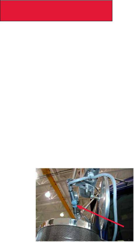
•The emission system requires an accurate Outside Air Temperature (OAT) reading in order to properly run its control algorithms.The OAT sensor is located in the driver’s side mirror assembly on Kenworth trucks and is shown in the figures below. If the body builder needs to modify the mirror assembly in any way, it is important the OAT sensor stay positioned on the mirror assembly. Running the vehicle without the OAT sensor connected will cause the MIL lamp to illuminate.. If needed, a replacement sensor can be ordered from your Kenworth dealer..
Figure 2-3: West Coast Mirror OAT sensor, located in overmold on mirror harness.
12/11 |
2-6 |
Section 2
Safety & Compliance
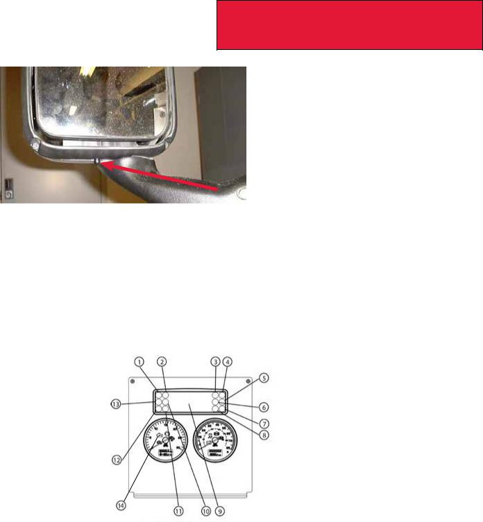
Figure 2-4: Aerodynamic Mirror OAT Sensor Location
•Coolant Sensor considerations are given in the Cooling section above
•The OBD/Diagnostic connector port is located below the dash to the left of the steering wheel.. This connector or its location may not be changed..
•Vehicles using EPA 2010 compliant engines must be equipped with a Malfunction Indicator Lamp (MIL) lamp..
This lamp is required to be an engine outline symbol as defined by ISO (International Standards Organization).The figure below shows the instrument cluster and MIL lamp position. Note this lamp location is fixed with respect to the controls and its location may not be changed if you are updating the warning lamp cards..
The MIL lamp will not be used with Medium Duty vehicles until 2013.
1 |
PTO |
5 |
High Exhaust System |
10 |
Brake Fail |
|
|
|
Temperature (HEST) |
|
|
2 |
Wait to Start |
6 |
Fasten Seat Belts |
11 |
High Beam |
3 |
Malfunction Indicator |
7 |
RH Turn Signal |
12 |
LH Turn Signal |
|
Lamp (MIL) |
|
|
|
|
4 |
Engine Brake |
8 |
Park Brake |
13 |
Check Transmission |
|
|
9 |
Multi-Function Display |
14 |
Check Engine Light |
Figure 2-5: Instrument Cluster for T170/T270/T370 used with EPA2010 Emission compliant engines.. The Check Engine lamp is symbol 21 and the MIL is symbol 8..
•In addition to the sensors and lamps above, the emission system also depends on signals from the exhaust DPF (Diesel Particulate Filter), SCR (Selective Catalytic Reduction), and NOx sensor.Wiring between these devices, the Dosing Control Unit (DCU) and engine ECM should not be tampered with or altered in any way.
2-7 |
12/11 |

Section 2
Safety & Compliance
Air Intake System
The following are highlights of some of the more common or critical aspects of this system..
•The air intake screen may not be blocked, either fully or partially
•Modification to the air intake system may not restrict airflow. For example, pipe diameter may not be reduced
•All sensors must be retained in existing locations
•To retain system seal, proper clamp torque must be used. Refer to service manual for proper clamp torque
Charge Air Cooler System
The following are highlights of some of the more common or critical aspects of this system..
•The Charge Air Cooler may not be modified
•The installation of engine overspeed shutdown devices must not introduce restriction in the intake system
•All plumbing associated with the charge air cooler may not be modified
12/11 |
2-8 |

Section 3
Dimensions
DIMENSIONS
This section is designed to provide enough information to successfully layout chassis in the body planning process. Only typical truck layouts and configurations are shown. Optional equipment may not be depicted. Please contact your local
Kenworth dealer if more information is desired.
ABBREVIATIONS AND DEFINITIONS
Throughout this section, and in other sections as well, abbreviations and specific terminology are used to describe certain characteristics on your vehicle.The charts below list the abbreviated terms used and provide definitions for terminology used.
TABLE 3-1. Abbreviations Used
AF |
After Frame – Frame rail overhang behind rear axle or measured from the centerline of tandem |
|
|
BOC |
Back of Cab |
|
|
BOF |
Bottom of Rail |
|
|
CA |
Back of cab to centerline of rear axle or centerline of tandems on tandem suspension |
|
|
FS |
Front suspension height from centerline of axle up to the bottom of the frame rail |
|
|
OAL |
Overall Vehicle Length |
|
|
SOC |
Side of Cab |
|
|
RS |
Rear suspension height from centerline of axle up to the bottom of the frame rail |
|
|
WB |
Centerline of front axle to centerline of rear axle or centerline of tandems on tandem suspension |
|
|
TABLE 3-2. Definitions
GAWR The maximum allowable weight each axle assembly is designed to carry, as measured at the tires, therefore including the weight of the axle assembly itself.. GAWR is established by considering the rating of each of its components (tires, wheels, springs, axle and steering system), and rating the axle on its weakest link.. The GAWR assumes that the load is equal on each side..
LADEN This is the weight condition of the truck with the front and rear axles loaded to their Gross Axle Weight Rating, GAWR..
UNLADEN This is the weight condition of the truck delivered from the PACCAR factory.This is without the following: body, driver, and tools. It does include fluids, but no fuel.
3-1 |
12/11 |
Section 3
Dimensions
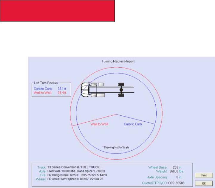
Prospector Turn Circle Analysis:
Please see Figure 3-1 as an example of Kenworth’s turn circle calculation made in Prospector for your specific chassis. Your local Kenworth dealer can provide this information to you.
Figure 3-1. Prospector Turn Circle Analysis
Please consult your local Kenworth Dealer for this information, as it is chassis specific.
12/11 |
3-2 |
Section 3
Dimensions
overall dimensions
This section includes drawings and charts of the following medium duty models: T170, T270 and T370..
On the pages that follow, detail drawings show particular views of each vehicle with dimensions being in inches and (mm).
They illustrate important measurements critical to designing bodies of all types.. See the “Table of Contents” at the beginning of the manual to locate the drawing that you need..
Kenworth also offers .dxf files and frame layouts of ordered chassis four weeks prior to build. Please speak to your sales person to request this feature when specifying your chassis..
* |
* |
* |
* |
|
* Dimensions are typical. Measurements will vary with axle, brake |
|
drum, tires and wheel selections |
figure 3-2. T170/T270/T370 Overall Height, and Length Dimensions [inches (mm)]
3-3 12/11

Section 3
Dimensions
TABLE 3-3. Hydraulic Brake Vehicles.T170 Single Rear Axle: Overall Fore-Aft Dimensions [inches (mm)]
WB |
OAL |
AF |
CA |
|
|
|
|
153 (3886) |
235..9 (5992) |
55 (1397) |
72 (1829) |
|
|
|
|
162 (4115) |
240..9 (6119) |
55 (1397) |
77 (1956) |
|
|
|
|
176 (4470) |
280..9 (7135) |
64 (1626) |
108 (2743) |
|
|
|
|
188 (4775) |
304..9 (7745) |
76 (1930) |
120 (3048) |
|
|
|
|
206 (5232) |
328..9 (8354) |
82 (2083) |
138 (3505) |
|
|
|
|
218 (5537) |
352..9 (8964) |
94 (2388) |
150 (3810) |
|
|
|
|
236 (5994) |
376..9 (9573) |
100(2540) |
168 (4267) |
|
|
|
|
245 (6223) |
384..9 (9777) |
99 (2515) |
177 (4496) |
|
|
|
|
TABLE 3-4. Hydraulic Brake Vehicles. T270/370 with Single Rear Axle: Overall Fore-Aft Dimensions [inches
(mm)]
WB* |
OAL |
AF |
CA |
153 (3886) |
235..9 (5992) |
55 (1397) |
72 (1829) |
|
|
|
|
162 (4115) |
240..9 (6119) |
55 (1397) |
77 (1956) |
|
|
|
|
176 (4470) |
280..9 (7135) |
64 (1626) |
108 (2743) |
|
|
|
|
188 (4775) |
304..9 (7745) |
76 (1930) |
120 (3048) |
|
|
|
|
206 (5232) |
328..9 (8354) |
82 (2083) |
138 (3505) |
|
|
|
|
218 (5537) |
352..9 (8964) |
94 (2388) |
150 (3810) |
|
|
|
|
236 (5994) |
376..9 (9573) |
100 (2540) |
168 (4267) |
|
|
|
|
245 (6223) |
384..9 (9777) |
99 (2515) |
177 (4496) |
|
|
|
|
254 (6452) |
424..9 (10793) |
130 (3302) |
186 (4724) |
|
|
|
|
260 (6604) |
448..9 (11402) |
148 (3759) |
192 (4877) |
|
|
|
|
272 (6909) |
462..9 (11758) |
150 (3810) |
204 (5182) |
|
|
|
|
* Air Brake Vehicles.. T270/T370 wheelbases for Single Rear Axle begin at 140 inches.. Tandem Rear axles begin at 175 inches.Wheelbase on Air Brake vehicles available in 1-inch increments.
12/11 |
3-4 |
Section 3
Dimensions
Detail Views
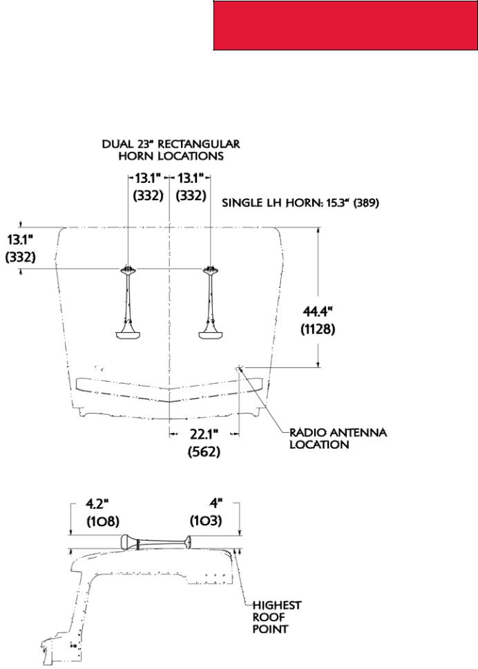
Top of Cab: Roof Mounted Options – T270/370
Figure 3-3. Top of Cab View, T270/T370, Roof Mounted Options
Figure 3-4. Side of Cab View, T270/370, Roof Mounted Options
3-5 12/11
Section 3
Dimensions
Detail Views
Back of Cab: Flush Mounted Flood Lamps – T270/370
|
25 (635) |
25 (635) |
|
|
|
High Mount Flood |
|
|
|
Lamp Elevation |
|
Mid Mount Flood |
|
|
|
Lamp Elevations |
|
|
|
|
|
62..4 |
|
|
|
(1585) |
|
Mid Mount Flood |
14..4 (365) |
14..4 (365) |
|
Lamp Location for |
|||
|
43..7 |
||
Vertical Tailpipe |
|
(1110) |
|
Back of Cab |
|
|
|
|
|
37..2 |
|
|
C/L |
(945) |
|
|
|
BOF |
Figure 3-5. Flush Mounted Flood Lamp Locations [inches (mm)]
12/11 |
3-6 |
Section 3
Dimensions
Detail Views
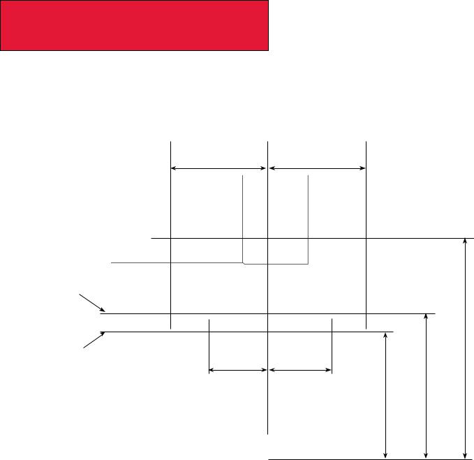
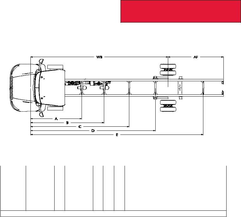
Crossmember Locations – T170
Figure 3-6. T170 Crossmember Location
TABLE 3-5 T170 Cross member. Location: measured from front axle centerlines [inches (mm)]
WB |
A |
CB |
B |
CB |
C |
D |
E |
206 |
101..8 (2585) |
Y |
121..1(3075) |
Y |
|
|
|
|
|
218 |
101..8 (2585) |
Y |
121..1(3075) |
Y |
|
|
|
|
|
236 |
101..8 (2585) |
Y |
121..1(3075) |
Y |
|
|
|
|
|
245 |
101..8 (2585) |
Y |
121..1(3075) |
Y |
|
|
|
|
|
254 |
101..8 (2585) |
Y |
162 (4125) |
Y |
|
|
|
|
|
260 |
101..8 (2585) |
Y |
162 (4125) |
Y |
|
|
|
|
|
272 |
101..8 (2585) |
Y |
162 (4125) |
Y |
1..) For without a square end of frame crossmember with an AF range of 80 (2032)
to 125(3175) a crossmember is installed at: E=WB+64..4”(1636mm)
2..) For AF range of 126 (3200) to 173(4394) a 2nd crossmember is installed at: E=WB+112..4”(2855 mm)
Y SPL100 Driveline centerbearing (CB) is mounted on this crossmember.
3-7 |
12/11 |
Section 3
Dimensions
Detail Views
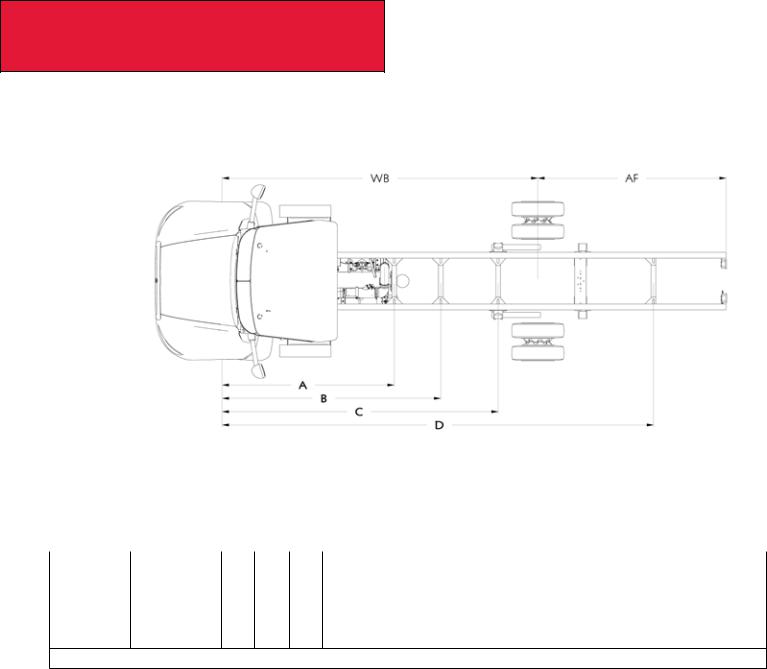
Crossmember Locations – T170
Figure 3-7. T170 Crossmember Location
TABLE 3-6 T170 Cross member. Location: measured from front axle centerlines [inches (mm)]
WB |
A |
CB |
C |
D |
E |
153 |
101..8 (2585) |
Y |
|
|
|
162 |
101..8 (2585) |
Y |
|
|
|
176 |
101..8 (2585) |
Y |
|
|
|
188 |
101..8 (2585) |
Y |
1..) For without a square end of frame crossmember with an AF range of 80 (2032)to 125(3175) a crossmember is installed at: E=WB+64..4”(1636mm)
2..) For AF range of 126 (3200) to 173(4394) a 2nd crossmember is installed at: E=WB+112..4”(2855 mm)
Y SPL100 Driveline center bearing (CB) is mounted on this cross member
12/11 |
3-8 |
Section 3
Dimensions
COMPONENTS
This section includes detail drawings and charts showing particular vehicle components with dimensions in inches and
(millimeters).. They illustrate important measurements critical to designing bodies of all types.. See the “Table of Contents” at the beginning of the manual to locate the drawing that you need..
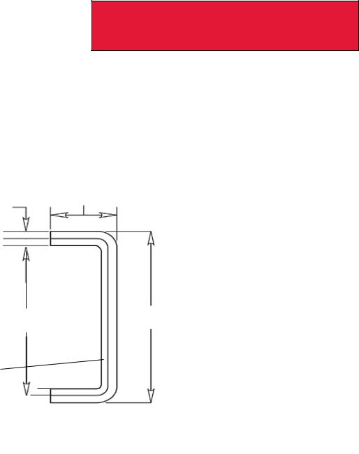
Frame Rail Configurations -T170/270/370
Note: Bottom of frame rail is a reference point that you can use to determine estimated heights of components and ground clearances..
W
T
Rail Heat
Treated
H
Optional
Insert, Heat
Treated
Shown
Figure 3-8. Frame Rail Dimensions and Properties [inches (mm)]
TABLE 3-7. Frame Rail Properties
Frame Rail or Insert |
|
Section |
RBM per Rail |
Weight per Inch |
Height H, |
Flange Width |
Thickness T, |
|
Model |
Modulus per |
|||||||
(1)(2) |
lbs-Inch |
per Pair, lbs |
inch (mm) |
W, inch (mm) |
inch (mm) |
|||
|
Rail, cu.in. |
|||||||
|
|
|
|
|
|
|
||
9-7/8 Frame Rail |
T170/T270 |
9..88 |
1,251,767 |
2..10 |
9..88 (251) |
3..46 (87..8) |
0..25 (6..4) |
|
|
|
|
|
|
|
|
|
|
10-5/8 Frame Rail |
T270/T370 |
14..8 |
1,776,000 |
2..90 |
10..63 (270) |
3..46 (87..8) |
0..31 (7..9) |
|
|
|
|
|
|
|
|
|
|
10-3/4 Frame Rail |
T270/T370 |
17..8 |
2,132,000 |
3..50 |
10..75 (273) |
3..46 (87..8) |
0..38 (9..5) |
|
|
|
|
|
|
|
|
|
|
9-7/8 Insert ONLY for |
T270/T370 |
9..57 |
1,149,000 |
2..00 |
9..88 (251) |
2..88 (73..0) |
0..25 (6..4) |
|
10-5/8 Frame Rail (2)(3) |
||||||||
|
|
|
|
|
|
|
||
|
|
|
|
|
|
|
|
|
10-5/8 Frame Rail with |
T270/T370 |
23..4 |
2,925,000 |
4..96 |
10..63 (270) |
3..46 (87..8) |
0..56 (14..3) |
|
9-7/8 Insert |
||||||||
|
|
|
|
|
|
|
||
|
|
|
|
|
|
|
|
|
10-3/4 Frame Rail with |
T270/T370 |
27..4 |
3,281,000 |
5..50 |
10..75 (273) |
3..46 (87..8) |
0..63 (15..9) |
|
9-7/8 Insert |
||||||||
|
|
|
|
|
|
|
||
|
|
|
|
|
|
|
|
(1)Yield Strength: 120,000 PSI
(2)Frame rails and inserts are heat treated..
(3)Full inserts start ahead of the steering gear and end at the end of frame..
(4)Partial inserts start 25 inches behind the center line of the front axle and end at the end of the frame..
3-9 |
12/11 |
Section 3
Dimensions
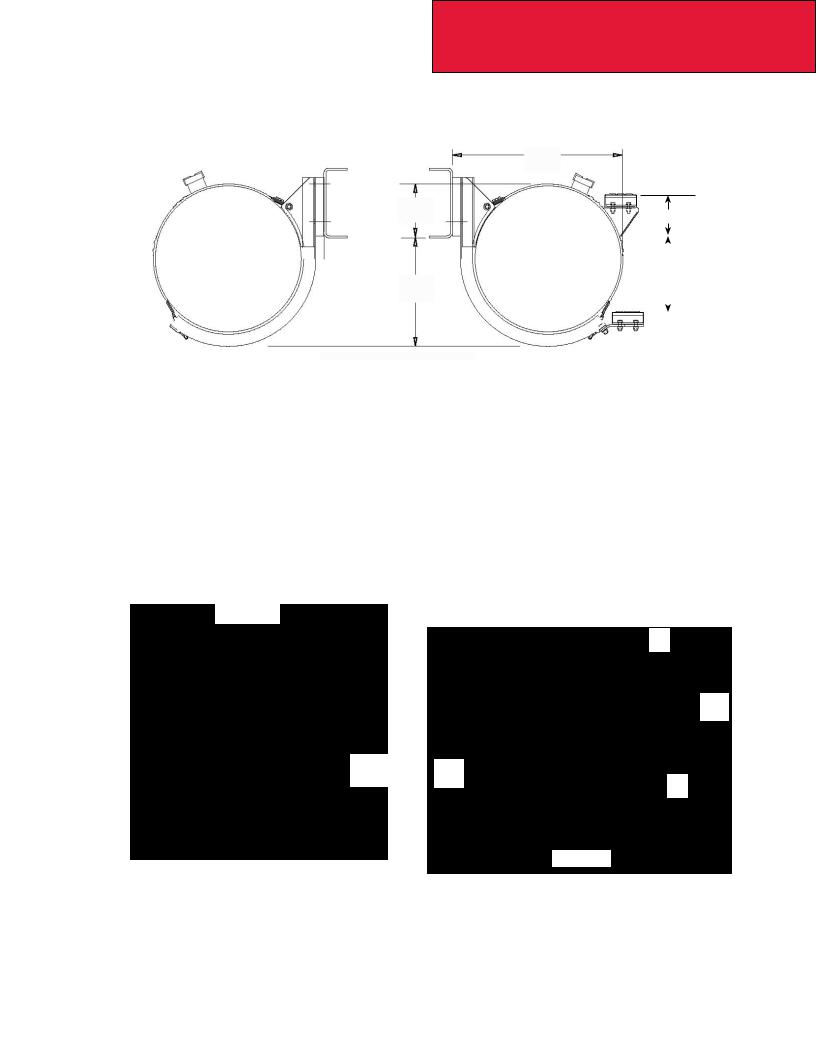
Battery Box – T270/370
Parallel Battery Box LH Under Cab for air braked truck or hydraulic braked truck with an accessory air system..
A |
B |
BOF |
C |
D |
|
|
|
Rear View |
|
|
FIGURE 3-9. T270/370 Battery Box Measurements [inches (mm)] |
|
||||
Table 3-8. T270/370 Battery Box Measurements [inches (mm)] |
|
||||
|
|
|
|
|
|
Type |
A, inch (mm) |
B, inch (mm) |
|
C, inch (mm) |
D, inch (mm) |
|
|
|
|
|
|
Hybrid |
33..4 (848) |
6..7 (170) |
|
9..5 (241) |
15..8 (401) |
|
|
|
|
|
|
Non-Hybrid |
33..4 (848) |
8..5 (215) |
|
9..3 (236) |
13..4 (354) |
|
|
|
|
|
|
Battery/Tool Box – T270/370
Parallel Battery Box LH Under Cab for Hydraulic braked Truck without an Accessory Air System or Tool Box Under Cab..
C |
BOF |
A |
|
B |
|
Rear View |
|
2..8 (70) |
|
FIGURE 3-10. T270/370 Battery/Tool Box Measurements [inches (mm)] |
|
Table 3-9. T270/370 Battery Box/Toolbox Dimensions [inches (mm)]
Type |
A, inch (mm) |
B, inch (mm) |
C, inch (mm) |
|
|
|
|
Non-Hybrid Battery Box |
8..5 (215) |
9..4 (239) |
33..4 (848) |
|
|
|
|
Hybrid Battery Box |
8..5 (215) |
9..5 (241..6) |
33..4 (848) |
|
|
|
|
Toolbox |
9..3 (236) |
9..2 (233) |
33 (848) |
|
|
|
|
12/11 |
3-10 |
Section 3
Dimensions
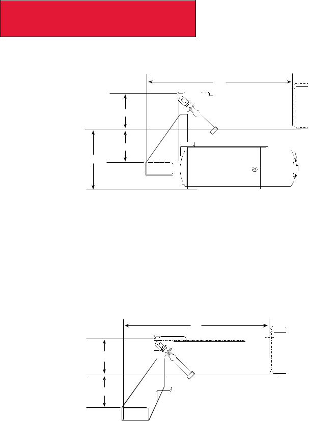
22-inch Fuel Tanks — T270/370
Round Fuel Tank Mounting
|
25..9 |
|
(658) |
11..0 |
6..7 (169) |
(279) |
BOF |
|
|
|
|
|
|
|
|
|
|
|
|
|
|
|
A |
10..4 (265) |
||
|
|
|
|
|
|
|
|
|
|
|
|
|
|
|
|
|
REAR VIEW |
REAR VIEW |
|
LEFT SIDE BEHIND CAB |
RIGHT SIDE UNDER CAB |
||
Figure 3-11. T270/370 22” Fuel Tank Mounting Measurements [inches (mm)] |
|||
|
|
|
|
22” Fuel Tank Height |
|
A, inch (mm) |
|
|
|
|
|
Standard |
|
16..3 (416) |
|
|
|
|
|
Raised 1 Inch |
|
15..3 (389) |
|
|
|
|
|
24.5-inch Fuel Tanks — T270/370
29..0

 (790)
(790)
4..8
(122)
2 0
0
 ..
.. 4
4 (518)
(518)
18..2 |
18..2 |
|
(462) |
|
|
(462) |
4..8 |
|
|
|
(122) |
|
32..1 (815) |
NO STEPS |
WITH STEPS |
Figure 3-12. T270/370 24..5” Fuel Tank Mounting Measurements.. With and without steps.. [inches (mm)]
3-11 |
12/11 |
Section 3
Dimensions
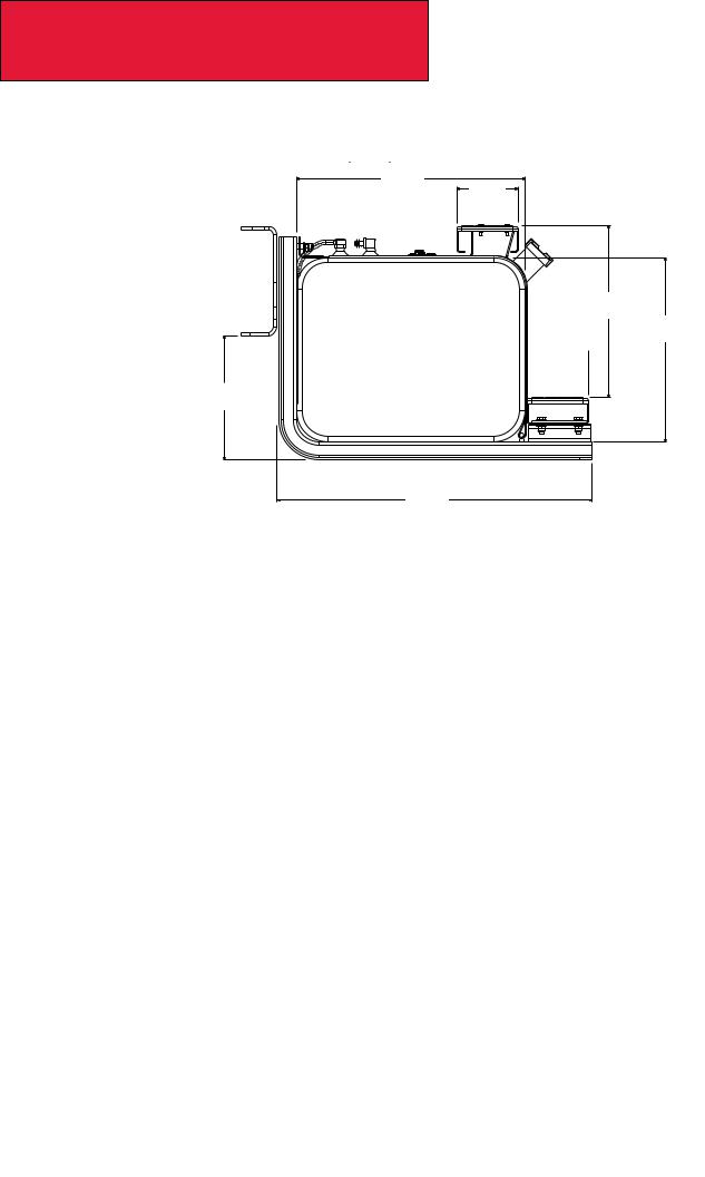
Rectangular Fuel Tank
Rectangular Fuel Tank Mounting
22..2
(564) 6 .
. .
. 0
0
(152)
1 6..8 (427) 17..9
6..0 (455)  (152)
(152) 
1 2..1 (307)
30..7
(780)
Figure 3-13. Rectangular Fuel Tank Measurements [inches (mm)]
12/11 |
3-12 |
 Loading...