


 Loading...
Section
Multiplexed Electrical System
Service Manual
Number PM819023/KM815057
Date 08/14/2012
2012 Multiplexed Electrical System Service
Manual — (P30-1011)

©2012 PACCAR Corporation
Confidentiality Notice: This document and the information contained herein is proprietary. It shall not be reproduced, copied or disclosed, in whole or in part, or used for manufacture without the written permission of PACCAR. You are hereby notified that any dissemination of this information is strictly prohibited.
ii |
PM819023/KM815057 (08/14/2012) |

Multiplexed Electrical System Service Manual
Table of Contents
Safety . . . . . . . . . . . . . |
1 |
Applies To . . . . . . . . . . . |
2 |
Exploded View . . . . . . . . . |
3 |
What's New . . . . . . . . . . |
4 |
General Information |
5 |
Special Tools. . . . . . . . . . |
6 |
Specifications . . . . . . . . . |
7 |
How It Works. . . . . . . . . . |
8 |
Maintenance . . . . . . . . . . |
9 |
Disassembly / Assembly . . . . |
10 |
Inspection . . . . . . . . . . . |
11 |
Troubleshooting . . . . . . . . |
12 |
Glossary . . . . . . . . . . . . |
13 |
Index . . . . . . . . . . . . . |
14 |
PM819023/KM815057 (08/14/2012) |
iii |

iv |
PM819023/KM815057 (07/06/2010) |

Multiplexed Electrical System Service Manual |
1 |
|
|
1 Safety
Important Notes. . . . . . . . . . . . 1 - 2
PM819023/KM815057 (08/14/2012) |
1 - 1 |
1 |
Multiplexed Electrical System Service Manual |
Important Notes
The simulate function within ESA can provide a valuable diagnosis tool. To ensure safe operation, certain CECU outputs are not accessible for simulation such as: cruise control, engine oil pressure and the park brake switch.
Simulation of gauges is also not permitted if the engine is running.
Replacing the CECU results in the odometer being reset. Take appropriate action to record the vehicle miles prior to removing the CECU.
CAUTION
Interrupting the communication or power supply during a control unit reflash could result in hardware damage.
ESA recognizes when a software update is required on a connected vehicle. If for some reason the user chooses not to reflash the control unit, ESA triggers a warning display. The LCD backlighting of the speedometer and outside air temperature blink for 1 minute. The warning is triggered at every key-on of the vehicle until the required update is performed to alert the operator or other technicians that a vehicle reflash is required.
ESA automatically identifies the version of CECU hardware when connected, and only permits software downloads that are applicable for that control unit. Software versions are not backwards compatible; a vehicle is rendered inoperative if a CECU without the correct software version is installed.
Check the program menu within ESA to see if an inoperative feature is disabled. This is very important when diagnosing an inoperative physical gauge on a CECU equipped vehicle. The gauge may have been previously disabled.
Instrumentation Service Information describing how to remove, disassemble, and reinstall instrumentation components is located
on ServiceNet. Before attempting any instrumentation repairs, the technician should have a complete understanding of the procedures described in ServiceNet.
This manual contains service manual information covering vehicles equipped with software version "CECU3 with Chassis Node" (P30-1011). For vehicles with prior CECU software versions (such as: "CECU3 with Chassis Node" (P30-1009), CECU3 (P30-1008), ICU (P30-1003), and CECU/CECU2 (P30-1002)) refer to earlier publications.
When replacing a chassis node, disconnect the batteries and do not reconnect them until node installation and all wiring connections are complete. A new chassis node and the CECU need to be powered up simultaneously during the node's first power cycle; otherwise a fault code message will appear in the main instrument
cluster between the speedometer and tachometer. This message indicates that the CECU is not recognizing the proper communication with the chassis node.
NAMUX 4 incorporates software in the CECU along with software in the instrument cluster. These software versions will often be linked together which will require both units to get updated should the other get updated. ESA will prompt the user if such a requirement is needed.
1 - 2 |
PM819023/KM815057 (08/14/2012) |

Multiplexed Electrical System Service Manual |
2 |
|
|
2 Applies To
Multiplexing Overview. . . . . . . . . 2 - 2
Models–Build Dates . . . . . . . . . . 2 - 2
PM819023/KM815057 (08/14/2012) |
2 - 1 |

2 |
|
Multiplexed Electrical System Service Manual |
|
|
|
Multiplexing Overview |
Models–Build Dates |
|
This manual provides service information covering trucks equipped with the multiplexed instrumentation system. Before attempting to make service repairs, the technician should be knowledgeable about the system design, components, operation and troubleshooting procedures for diagnosing multiplexed instrumentation problems.
How communication works in a multiplex system: Each major subsystem in the truck’s electrical system is operated by a control module that sends and receives data to and from a central hub computer. The central hub computer is called the CECU (Cab Electronic Control Unit). Since we’re into the third generation now, we sometimes call it CECU3.
The CECU receives data related to controlling the various devices of the electrical system. It then makes decisions based on that input and sends information to each of the subsystem system control modules (nodes) about what that node should do with the components it controls.
This new generation incorporates much of the same architecture from previous designs with added data communications with more control modules. The software has been upgraded to incorporate interlocks to ensure safety, maximize vehicle performance and simplify driver interaction.
Identifying which control unit is in the vehicle helps determine what features are present and also aids in troubleshooting.
Control |
Hardware Part Number |
Software Version |
Models |
Engine Emissions |
Production Built |
|
Unit |
Level |
Dates |
||||
|
|
|
||||
ICU |
Q21-1029-X-XXX |
P30-1003-XXX |
PB: 357, 378, 379, 385, 386 |
1998, 2004 |
2005 - 2006 |
|
|
|
|
KW: C500, T600, T800, W900, |
|
|
|
|
|
|
Off-Highway |
|
|
|
CECU / CECU2 |
Q21-1055-X-XXX / |
P30-1002-XXX |
PB: 365, 367, 384, 386, 388, 389 |
2007 |
2007 - 2009 |
|
|
Q21-1075-X-XXX |
|
KW: C500, T440/T470, T660, |
|
|
|
|
|
|
T800, W900, Off-Highway |
|
|
|
|
|
|
PB: 387 |
|
2008 - 2009 |
|
|
|
|
KW: T2000 |
|
|
|
|
|
|
PB: 325, 330, 335, 340 |
|
2009 |
|
CECU3 |
Q21-1076-X-XXX |
P30-1008-XXX |
PB: 325, 330, 337, 348, 387 |
2010 |
2010 - present |
|
|
|
|
KW: T170, T270, T370, T700 |
|
|
|
CECU3 with |
Q21-1076-X-XXX with |
P30-1009-XXX |
PB: 365, 367, 384, 386, 388, 389 |
2010 |
2010 - present |
|
Chassis Node |
Q21-1077-X-XXX |
|
KW: C500, T440/T470, T660, |
|
|
|
|
|
|
T800, W900, Off-Highway |
|
|
|
|
|
|
PB: 365, 367, 384, 386 |
2010 |
2010 - 2011 |
|
|
|
|
KW: T660, T800 |
|
|
|
CECU3 with |
Q21-1076-X-XXX with |
P30-1011-XXX |
PB: 579 |
2010 |
2011 - present |
|
Chassis Node |
Q21-1077-X-XXX |
|
KW: T680 |
|
|
2 - 2 |
PM819023/KM815057 (08/14/2012) |
Multiplexed Electrical System Service Manual |
2 |
Control Unit Identification
Control unit identification can be made using a few methods:
•Searching using the Electronic Catalog (ECAT)
•Connecting using the Electronic Service Analyst (ESA)
•Menu Control Switch (MCS) of the information display
Using ECAT or ESA are the easiest and most exact ways of determining the type of control unit in the truck.
Electronic Catalog (ECAT) Identification
ECAT provides a parts list “as built” and Bill of Materials information for each specific truck. The catalog is searchable, and contains the part number and identification of the trucks instrument panel control unit.
•ICU Part Number Q21-1029-X-XXX
•CECU Part Number Q21-1055-X-XXX
•CECU2 Part Number Q21-1075-X-XXX
•CECU3 Part Number Q21-1076-X-XXX
•Chassis Node Part Number Q21-1077-X-XXX
The blank digits (denoted by "X") in the above part numbers represent:
•"-X" is the hardware revision.
•"-XXX" is the software boot loader version.
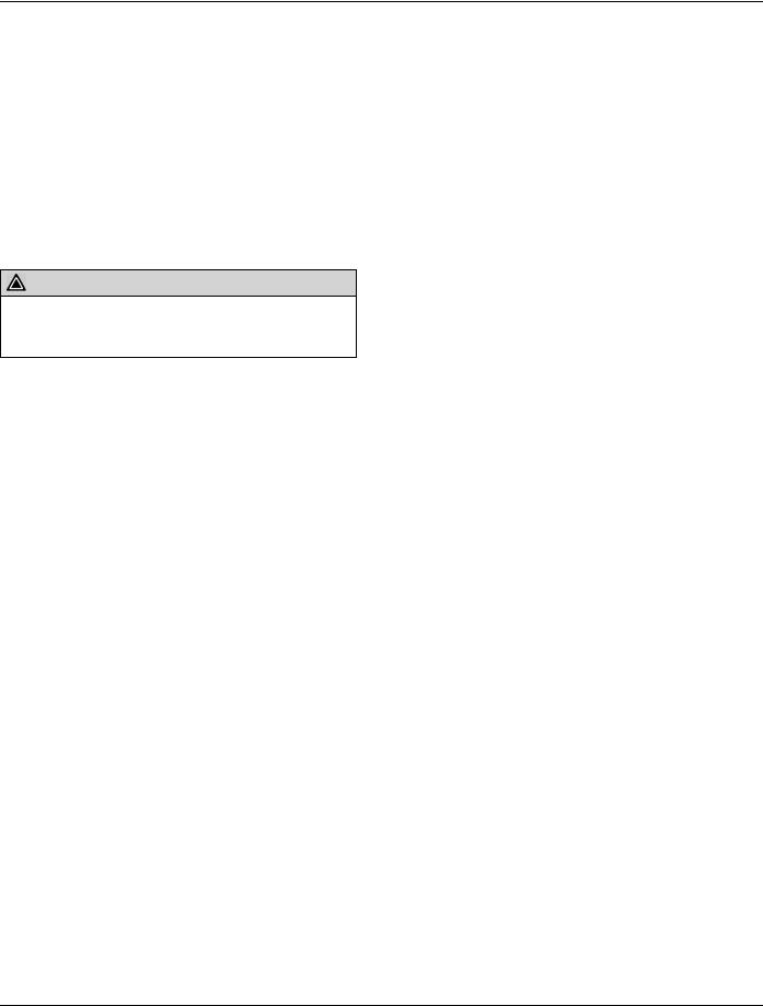
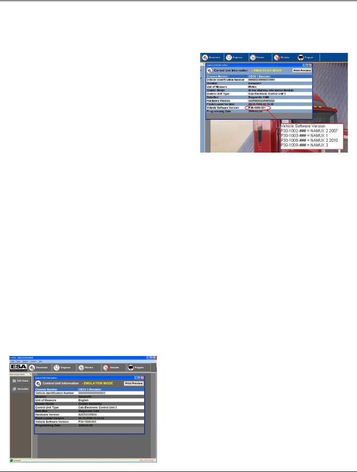
Electronic Service Analyst (ESA) Identification
Connecting using ESA brings up a control unit information window. In this window, the sixth line item is the Control Unit Type and identifies whether the truck has an ICU or CECU. It also details the variant of the CECU.
Line item ten of this Control Unit Information window displays the current Vehicle Software Version. This details the current CECU software and programming date that is presently installed on the vehicle.
Upon connection, ESA recognizes if a software update has been issued for the control unit within the connected vehicle. If an update is required, ESA prompts the technician to perform the update operation.
MCS Identification
For vehicles equipped with the information display, control unit identification is possible via the Menu Control Switch (MCS). Using the MCS knob, select the "Truck Information" menu. Use this menu to look up the "CECU SW Ver." Software version P30-1002-XXX can denote either a CECU or CECU2.
•ICU Software P30-1003-XXX
•CECU Software P30-1002-XXX
•CECU2 Software P30-1002-XXX
•CECU3 Software P30-1008-XXX
•CECU3 with Chassis Node Software P30-1009-XXX
•CECU3 with Chassis Node Software P30-1011-XXX
PM819023/KM815057 (08/14/2012) |
2 - 3 |

2 - 4 |
PM819023/KM815057 (08/14/2012) |
Multiplexed Electrical System Service Manual |
3 |
|
|
3 Exploded View
Control Unit Location . . . . . . . . . 3 - 2
PM819023/KM815057 (08/14/2012) |
3 - 1 |
3 |
Multiplexed Electrical System Service Manual |
Control Unit Location
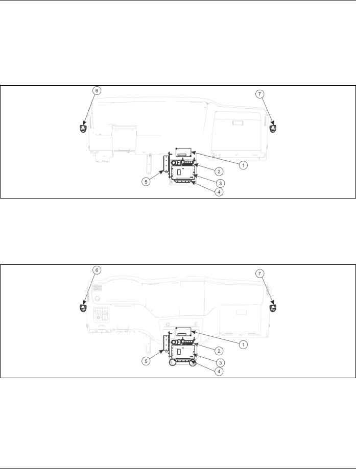
CECU Locations
The heart of the multiplexed instrumentation system is the CECU. The unit is located in the center of the dash, beneath the cupholders.
Typical CECU Locations (Kenworth)
1. |
AMOT module |
5. |
ELS Amplifier |
|
2. |
Allison Transmission |
6. |
Driver Door Controller |
|
3. |
Cab ECU |
|||
|
|
|||
4. |
ABS ECU |
7. |
Passenger Door Controller |
Typical CECU Locations (Peterbilt)
1.AMOT module
2.Allison Transmission
3.Cab ECU
4.ABS ECU
5.ELS Amplifier
6.Driver Door Controller
7.Passenger Door Controller
3 - 2 |
PM819023/KM815057 (08/14/2012) |
Multiplexed Electrical System Service Manual |
3 |
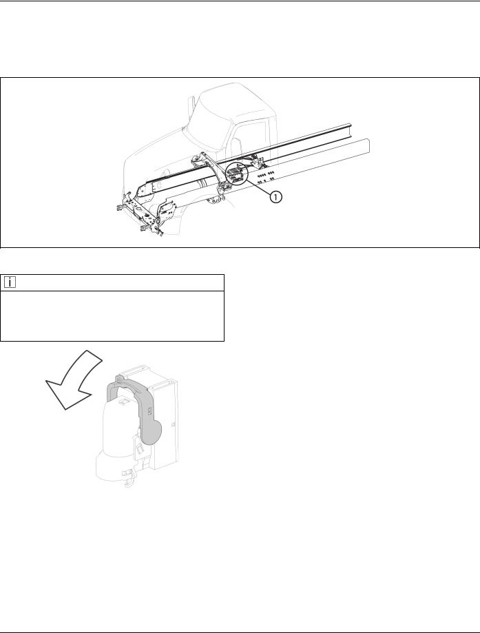
Chassis Node Locations
The chassis node is located below the driver side door.
Typical Chassis Node Location
1. Chassis Node
NOTE
Chassis Nodes and connectors are painted over with frame paint. To release the connectors, it will be necessary to scrape away the paint to access and release the connector locking lever.
PM819023/KM815057 (08/14/2012) |
3 - 3 |

3 - 4 |
PM819023/KM815057 (08/14/2012) |

Multiplexed Electrical System Service Manual |
4 |
|
|
4 What's New
Software P30-1011 Features . . . . . . 4 - 2
PM819023/KM815057 (08/14/2012) |
4 - 1 |

4 |
Multiplexed Electrical System Service Manual |
Software P30-1011 Features
NOTE
Software versions are not backwards compatible; this manual contains service manual information covering vehicles equipped with software version "CECU3 with Chassis Node" (P30-1011). For vehicles with prior CECU software versions (such as: "CECU3 with Chassis Node" (P30-1009), CECU3 (P30-1008), ICU (P30-1003), and CECU/CECU2 (P30-1002)) refer to earlier publications. A vehicle is rendered inoperative if a CECU without the correct software version is installed.
The most notable change to NAMUX is the factory programmed interlocks. Interlocks are defined as parameters that must be validated before a function will engage. For example, the system will not allow the vehicle to move if the park brake switch has not been de-activated.
The Menu Control Switch (MCS) now has the 'back' function as a dedicated button on the menu control switch on the dash. It is not a menu selection in the program.
P30-1011 features fewer hardwired circuits and more communications over the CAN networks.
The fault messaging capabilities have improved with this new release. The information to the driver is more complete and can provide the driver with general action items for each warning icon.
The program itself has improved capabilities with regard to trip information. There are 4 individual trip odometers that the user can customize to fit their needs.
If there is a data communication failure between the CECU and Instrument Cluster the Cluster Display will show a message indicating communication failure. This is intended to alert the driver that the Instrument Cluster is not displaying the gauges accurately and it indicates a physical failure on the I-CAN.
New Systems
Brief overview of some of the newly introduced systems of the latest software version.
Steering Wheel Controls (cruise and radio)
The multiplexed steering wheel is a carry-over design from other PACCAR markets. It communicates on the C-CAN line for audio and cruise control inputs from the operator.
Radio
The radio is now on the C-CAN databus.
Virtual Gauges/Navigation/Telematics Unit (optional)
This unit provides vehicle information to the operator and receives the information from the V-CAN. The display provides real time information in the form of gauges. It is also connected to the C-CAN for audio output.
Rear Sleeper Radio Controls (optional)
The rear sleeper audio controls communicates signals from the control panel in the sleeper to allow the occupant to control the audio from the sleeper.
HVAC
All air conditioning inputs are communicated to the controller through the C-CAN. Input for the HVAC system may come from sensors used by the engine computer or cab computer. For example, the outside air temperature sensor is mounted to the mirror and the signal must be sent through the door control module and the cab control module before being received by the HVAC controller.
Electric Over Air Switches
Electric Over Air (EOA) switches initiate electrical signals to actuate air valves in order to activate and deactivate air functions (such as: suspension dumps, differential locks, PTO switches, trailer switches, etc.).
There are a total of eight available EOA general function switches with four additional hardwired
4 - 2 |
PM819023/KM815057 (08/14/2012) |

Multiplexed Electrical System Service Manual |
4 |
lifter/pusher axle switches. The eight general switches are inputs into the CECU while the four hardwired switches are wired directly to the air solenoids with no software interlocks or CECU control.
For detailed information on the EOA interlocks refer to Electric Over Air Switch Interlocks on page 8-11 in the "How It Works" section of this manual.
Exterior Lighting Self Test
The Exterior Lighting Self Test (ELST) is intended to be operator activated and used to enhance the vehicle pre-drive inspection.
When initiated, the ELST toggles between two exterior lighting sequences. The ELST tests the functionality of certain exterior lights.
The ELST can be activated from a dash switch that is accessible from outside the cab or by the optional remote keyless key fob transmitter.
Cab Dimmer
The cab dimmer switch is a momentary up/down dash switch that allows the user to raise or lower the dash backlighting illumination levels.
The vehicle has a day time brightness setting that is independent of the night time brightness setting.
Door Controls
The Door Control System (DCS) operates with CECU electrical architecture to enable the user to raise/lower the door windows, lock/unlock door locks, adjust mirror position, and activate mirror heat.
Body CAN
There is a dedicated communication line (B-CAN) for customer installed control units. This dataline may be used by body builders to add like protocol control units. For more information regarding the B-CAN, refer to the appropriate Body Builder Manual.
PM819023/KM815057 (08/14/2012) |
4 - 3 |

4 - 4 |
PM819023/KM815057 (08/14/2012) |

Multiplexed Electrical System Service Manual |
5 |
|
|
5 General Information
Service Resources . . . . . . . . . . 5 - 2
PM819023/KM815057 (08/14/2012) |
5 - 1 |
5 |
Multiplexed Electrical System Service Manual |
Service Resources
Disabled Gauges
With the CECU, disabling a component turns the component off completely. The disabled component is removed from all signal
transmissions in order to allow the other features on the vehicle faster communication. A disabled gauge will not function or communicate with the control unit.
NOTE
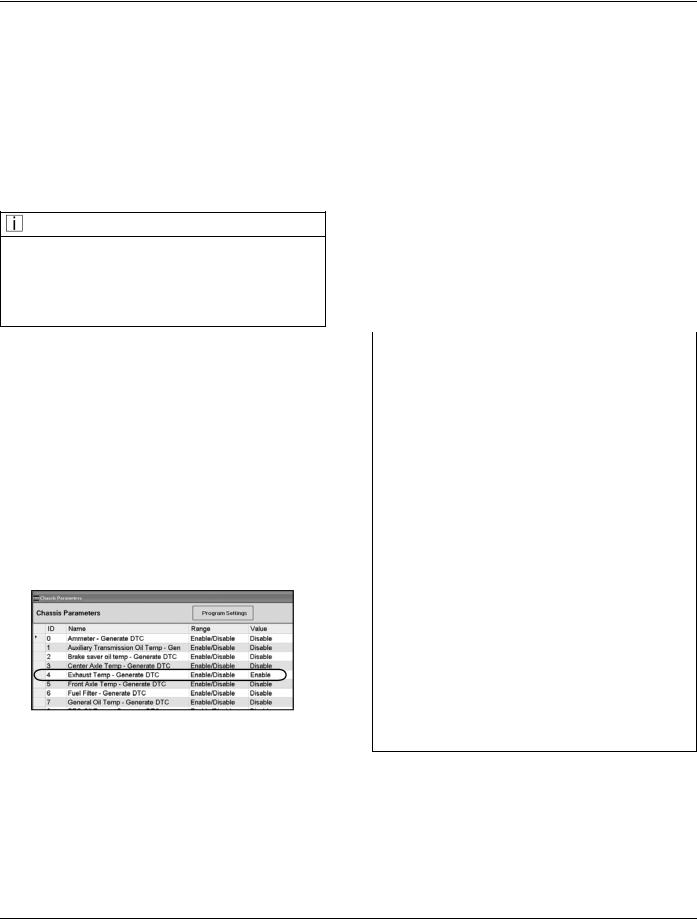
Check the program menu to see if an inoperative feature is disabled. This is very important when diagnosing an inoperative gauge on a CECU equipped vehicle. The gauge may have been previously disabled.
When a service technician installs an optional gauge in the multiplexed instrumentation system, the newly installed gauge will initially be disabled. Because the gauge is not factory-installed, the technician must program the CECU to monitor it. Until the CECU is programmed, the link between the CECU and the gauge is termed “disabled” – that is, the CECU is prevented from detecting errors, and also from logging and displaying diagnostic trouble codes (DTCs).
To program the CECU and enable gauges, select “Program”. If the gauge value is “Disable”, change it to “Enable”.
Once the CECU is programmed and the link to the gauge is “enabled”, the CECU monitors it, diagnoses errors like “shorts” and “opens”, logs DTCs for troubleshooting, and displays the DTCs on ESA’s “Diagnose” screen.
Communication Diagram
Communication diagrams illustrate the signal transmissions between components (switches, sensors, control units, CAN lines, etc.) necessary to perform system functions.
ControllerAreaNetwork(CAN)Communication
The following diagram provides an example of the communication lines and signal paths of a typical multiplexed vehicle. Determining the correct communication lines that provide a signal to the CECU and where these circuits interconnect, help pinpoint possible trouble areas. Sometimes these connections become loose, have bent or misaligned pins, and visually inspecting them may help identify why other electrical problems may be occurring.
Network |
Description |
What’s on the Network |
V-CAN |
Vehicle |
Transmission |
|
powertrain |
Engine |
|
|
ABS |
|
|
telematics (optional)¹ |
D-CAN |
Diagnostic |
Diagnostic connector |
F-CAN |
Frame |
Chassis Node |
|
components |
|
I-CAN |
Instruments |
Instrument cluster |
C-CAN |
Cab |
PACCAR Display or Radio |
|
|
Door controllers |
|
|
HVAC |
|
|
Remote Sleeper Audio (optional) |
|
|
Multifunction steering wheel (optional) |
B-CAN |
Body Builder |
Aftermarket devices² |
E-CAN |
Engine Input |
Turbo |
|
|
Humidity Sensor |
|
|
EGR |
A-CAN³ |
Aftertreatment |
NOx sensors |
|
|
Doser Control Unit |
|
|
Aftertreatment control unit |
¹Not all telematics units will be recognized by the CECU architecture. ²Telematic units connected to the BCAN will not be recognized
by the CECU. Any device spliced into a CAN wire will not be recognized by the CECU architecture.
³For vehicles built with PACCAR MX engine.
5 - 2 |
PM819023/KM815057 (08/14/2012) |
Multiplexed Electrical System Service Manual |
5 |
|
|
CAN Communication Interface Diagram |
|
|
|
|
|
|
|
PM819023/KM815057 (08/14/2012) |
5 - 3 |
5 |
Multiplexed Electrical System Service Manual |
CECU Details
The heart of the multiplexed instrumentation system is the CECU. See Control Unit Locations on page 3-2 for illustrations depicting the physical position of the control unit.
The CECU receives data related to controlling the various devices of the electrical system. It then makes decisions based on that input and sends information to subsystem system control modules (nodes) about what that node should do with the components it controls.
CECU
CECU Connector Identification
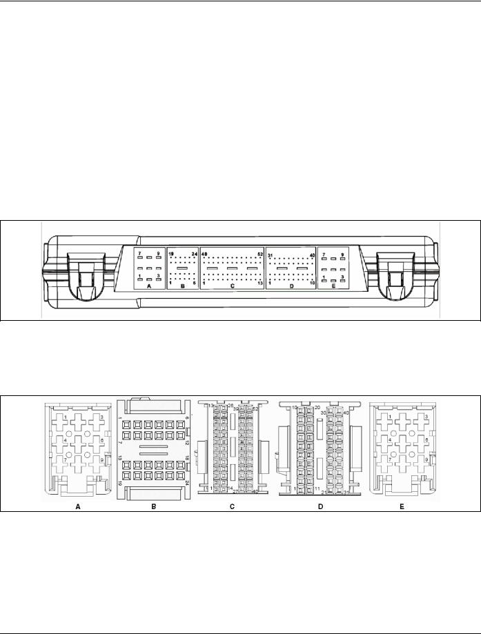
There are 5 electrical connectors that plug into the CECU.
•Connector A - 9 pins
•Connector B - 24 pins
•Connector C - 52 pins
•Connector D - 40 pins
•Connector E - 9 pins
For an illustration of the side view of a CECU showing where the harness connectors attach into the control unit, see CECU Figure. This figure identifies connector position on the control unit as well as individual connector pin locations.
For connector face views at the harness connectors that plug into the CECU, see CECU Connector Face Views Figure. These connectors
CECU Connector Face Views
all branch from the instrument panel harness that routes behind the dash.
5 - 4 |
PM819023/KM815057 (08/14/2012) |

Multiplexed Electrical System Service Manual |
5 |
|
|
CECU Comparison Chart - (Pinout)
Conn |
Pin Number |
Circuit Function |
A |
1 |
CVSG power |
|
2 |
Power - battery |
|
3 |
Cab dome lamp output |
|
4 |
Menu control switch power |
|
5 |
Ground |
|
6 |
Menu control switch ground |
|
7 |
Dash/panel illumination |
|
8 |
Auxiliary backlighting |
|
9 |
Power - battery |
B |
1 |
Menu control switch encode A |
|
2 |
Menu control switch encode B |
|
3 |
Menu control switch enter |
|
4 |
Exterior lighting self test input |
|
5 |
Ignition input (Start) |
|
6 |
Dome lamp input |
|
7 |
Seat belt telltale |
|
8 |
Cruise set |
|
9 |
Cruise resume |
|
10 |
Back-up alarm mute |
|
11 |
Retarder select 1 |
|
12 |
Retarder select 2 |
|
13 |
Clutch switch |
|
14 |
Headlamps active |
|
15 |
PTO set |
|
16 |
PTO resume |
|
17 |
Engine fan override |
|
18 |
Regen enable |
|
19 |
Inhibit regen |
|
20 |
ABS off road |
|
21 |
Marker lamp (Tractor) |
|
22 |
LVD input |
|
23 |
Transfer Case Engaged |
|
24 |
Reserve - passenger seat occupancy sensor |
Conn |
Pin Number |
Circuit Function |
C |
1 |
Power supply +5V sensors |
|
2 |
Analog return |
|
3 |
Electric over air switch 1 input |
|
4 |
Not used |
|
5 |
Spare analog input |
|
6 |
Air pressure transducer - primary |
|
7 |
Air pressure transducer - secondary |
|
8 |
Air pressure transducer - application |
|
9 |
Gauge Sensor 1 |
|
10 |
Air filter restriction |
|
11 |
Gauge Sensor 2 |
|
12 |
Dimmer switch (up) |
|
13 |
Dimmer switch (down) |
|
14 |
CVSG data |
|
15 |
CVSG return |
16Outside air temperature (Pre2010 engines only)
17 |
Electric over air switch 3 input |
18 |
Electric over air switch 4 input |
19 |
Electric over air switch 5 input |
20 |
Electric over air switch 6 input |
21 |
Transmission oil temperature - main |
22 |
Electric over air switch 7 input |
23 |
Pyrometer (Pre-2007 engines only) |
24 |
Electric over air switch 8 input |
25 |
Analog return |
26 |
Electric over air switch 2 input |
27 |
Spare |
28 |
Spare |
29 |
Spare |
30 |
Gauge Sensor 3 |
31 |
Wiper resistor ladder |
32 |
Turn signal resistor ladder |
33 |
LVD battery voltage |
34 |
Gauge Sensor 4 |
35 |
C-CAN ground |
36 |
Not used |
37 |
C-CAN high |
38 |
C-CAN low |
39 |
Trailer stop lamp relay |
40 |
D-CAN high |
41 |
D-CAN low |
42 |
D-CAN ground |
43 |
B-CAN high |
44 |
B-CAN low |
45 |
B-CAN ground |
46 |
Marker flash |
47 |
Windshield washer pump |
48 |
DRL interrupt |
49 |
Marker lamp (Trailer) (Kenworth) |
50 |
Fuel Level Sender Select |
51 |
Headlamp flash |
52 |
Headlamp high/low |
PM819023/KM815057 (08/14/2012) |
5 - 5 |

5 |
|
|
|
Multiplexed Electrical System Service Manual |
|
|
|
|
|
|
|
|
|
|
Conn |
Pin Number |
Circuit Function |
|
|
D |
1 |
Power - ignition |
|
|
|
|
2 |
General purpose wakeup |
|
|
|
3 |
Power - accessory |
|
|
|
4 |
Hazard |
|
|
|
5 |
Brake switch |
|
|
|
6 |
Spare digital input |
|
|
|
7 |
Park brake active |
|
|
|
8 |
Fog lamps (1st set) |
|
|
|
9 |
MCS back switch |
|
|
|
10 |
Cruise on/off |
|
|
|
11 |
Interaxle lock telltale |
|
|
|
12 |
Park lamp (Kenworth) |
|
|
|
13 |
Tractor ABS telltale |
|
|
|
14 |
Trailer ABS telltale |
|
|
|
15 |
Check engine telltale |
|
|
|
16 |
Stop engine telltale |
|
|
|
17 |
Windshield wiper (fast) |
|
|
|
18 |
Secondary fog lamps |
|
|
|
19 |
Editable telltale 1 |
|
|
|
20 |
Editable telltale 2 |
|
|
|
21 |
Editable telltale 3 |
|
|
|
22 |
Spare |
|
|
|
23 |
Editable telltale 5 |
|
|
|
24 |
Editable telltale 6 |
|
|
|
25 |
Editable telltale 7 |
|
|
|
26 |
Spare |
|
|
|
27 |
Spare |
|
|
|
28 |
Dash buzzer 1A |
|
|
|
29 |
Dash buzzer 1B |
|
|
|
30 |
Dash buzzer 1C |
|
|
|
31 |
Dash buzzer 2 |
|
|
|
32 |
F-CAN high |
|
|
|
33 |
F-CAN low |
|
|
|
34 |
I-CAN high |
|
|
|
35 |
I-CAN low |
|
|
|
36 |
I-CAN ground |
|
|
|
37 |
V-CAN high |
|
|
|
38 |
V-CAN low |
|
|
|
39 |
V-CAN ground |
|
|
|
40 |
V-CAN low terminated |
|
E |
1 |
Idle timer relay |
|
|
|
|
2 |
Windshield wiper relay |
|
|
|
3 |
Ignition relay (Start) |
|
|
|
4 |
Cab marker/clearance lamp relay |
|
|
|
5 |
Ground |
|
|
|
6 |
LVD Bus 1 |
|
|
|
7 |
Park lamp relay |
|
|
|
8 |
Trailer marker/clearance lamp relay |
|
|
|
9 |
Mirror heat relay |
|
5 - 6 |
PM819023/KM815057 (08/14/2012) |
Multiplexed Electrical System Service Manual |
5 |
Chassis Node Details
The node that receives information from the CECU to control exterior lighting, Electric over Air controls, and windshield wipers is called the chassis node. The chassis node serves as a bidirectional conduit for both information and control.
Chassis Node Connector Identification
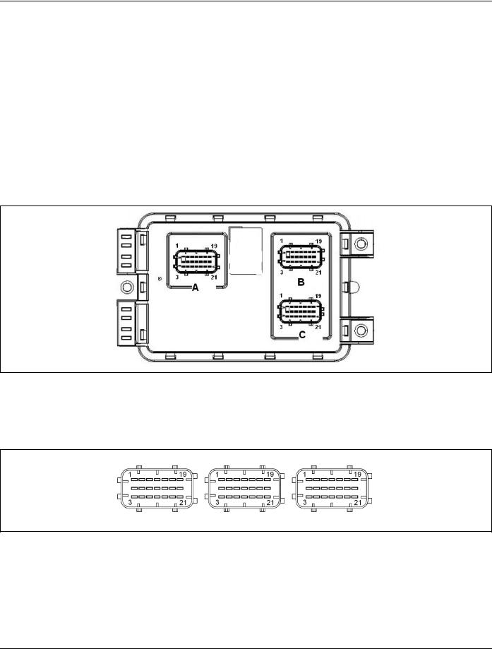
There are three 21-pin electrical connectors that plug into the Chassis Node.
•Connector A - 21 pins
•Connector B - 21 pins
•Connector C - 21 pins
For an illustration of the side view of a Chassis Node showing where the harness connectors attach into the control unit, see Chassis Node Figure. This figure identifies connector position on the control unit as well as individual connector pin locations.
Chassis Node Figure
For connector face views at the harness connectors that plug into the Chassis Node, see Chassis Node Connector Face Views Figure.
Chassis Node Connector Face Views
PM819023/KM815057 (08/14/2012) |
5 - 7 |

5 |
Multiplexed Electrical System Service Manual |
Chassis Node Comparison Chart - (Pinout)
Conn |
Pin Number |
Circuit Function |
A |
1 |
Left headlamp low beam output (PWM) |
|
2 |
Power - ignition input |
|
3 |
Ground |
|
4 |
Battery power - 1 |
|
5 |
Neutral switch input |
|
6 |
Fuel level 1 input |
|
7 |
Right headlamp high beam output |
|
8 |
Backup switch input |
|
9 |
Fuel level 2 input |
|
10 |
Reverse loads (Peterbilt) |
|
|
Snowplow (Kenworth) |
|
11 |
Spare digital input |
|
12 |
Spare analog input |
|
13 |
Left headlamp high beam output |
|
14 |
(reserved) |
|
15 |
Spare analog input |
|
16 |
Battery power - 2 |
|
17 |
(reserved) |
|
18 |
F-CAN high |
|
19 |
Right headlamp low beam output (PWM) |
|
20 |
(reserved) |
|
21 |
F-CAN low |
B |
1 |
Battery power - 3 |
|
2 |
Right turn/stop rear output (Tractor) |
|
3 |
Power supply +5V sensors |
|
4 |
Left turn front/side output |
|
5 |
Fuel filter restriction input |
|
6 |
Transmission oil temperature - auxiliary input |
|
7 |
Right turn front/side output |
|
8 |
Spare analog input |
|
9 |
General oil temperature input |
|
10 |
Battery power - 4 |
|
11 |
Spare analog input |
|
12 |
Reserve for remote accelerator |
|
13 |
Left turn/stop rear output |
|
14 |
Reserve for clutch wear sensor |
|
15 |
Driving/fog lamps output |
|
16 |
Left turn trailer output |
|
17 |
Ammeter input |
|
18 |
Battery power - 7 |
|
19 |
Battery power - 5 |
|
20 |
Left turn front/DRL output |
|
21 |
Right turn front/DRL output |
Conn |
Pin Number |
Circuit Function |
C |
1 |
Analog return |
|
2 |
Electric over air switch 1 output |
|
3 |
Electric over air switch 2 output |
|
4 |
Transfer case oil temperature input |
|
5 |
Electric over air switch 3 output |
|
6 |
Electric over air switch 4 output |
|
7 |
PTO oil temperature input |
|
8 |
Electric over air switch 5 output |
|
9 |
Electric over air switch 6 output |
|
10 |
Rear axle temperature input |
|
11 |
Electric over air switch 7 output |
|
12 |
Electric over air switch 8 output |
|
13 |
Front axle temperature input |
|
14 |
DRL headlamps (Perterbilt) |
|
15 |
Battery power - 8 |
|
16 |
Center/steer axle temperature input |
|
17 |
Windshield wiper motor control output |
|
18 |
Trailer engine coolant valve |
|
19 |
Battery power - 8 |
|
20 |
Right turn trailer output |
|
21 |
Back-up alarm control output |
5 - 8 |
PM819023/KM815057 (08/14/2012) |

Multiplexed Electrical System Service Manual |
7 |
|
|
7 Specifications
Parameter Part Numbers. . . . . . . . 7 - 2
PM819023/KM815057 (08/14/2012) |
7 - 1 |

7 |
Multiplexed Electrical System Service Manual |
Parameter Part Numbers
CECU Parameters
Parameters are used to identify to the CECU what features are present on a vehicle. The parameters can be altered by a dealer to enable, disable, or assign certain functionality to that feature.
Parameter part numbers are searchable in ECAT and allow a dealer to determine what parameters were set at the factory. Also, if adding a new feature to a vehicle, the corresponding parameter needs to be programmed to the CECU and enabled.
CECU Parameter |
Parameter |
Min. |
Max. |
Explanation |
|
Part Number |
Description |
Value |
Value |
||
|
|||||
Q30-1024-000 |
ABS installed |
0 |
1 |
Parameter controls DTC's related to ABS system. |
|
|
|
|
|
Value 0/Disabled means ABS is not installed and DTC's are disabled |
|
|
|
|
|
Value 1/Enabled means ABS is installed and DTC's are enabled. |
|
Q30-1024-001 |
AfterTreatmentRegeneration |
0 |
1 |
Parameter is used to allow information from the engine to turn on the |
|
|
Function |
|
|
telltales for the high exhaust temperature (emission system temperature) |
|
|
|
|
|
and regeneration filter. |
|
|
|
|
|
Value 0/Disabled means not allow cluster to display DPF and HEST |
|
|
|
|
|
telltales on cluster. |
|
|
|
|
|
Value 1/Enabled means allow cluster to display DPF and HEST telltales on |
|
|
|
|
|
cluster. |
|
Q30-1024-002 |
ATC installed |
0 |
1 |
Currently has no effect on functionality. Parameter will be used to determine |
|
|
|
|
|
the presence of traction control. |
|
|
|
|
|
Value 0/Disabled means ATC is not installed. |
|
|
|
|
|
Value 1/Enabled means ATC is installed. |
|
Q30-1024-003 |
Retarder Range Map |
0 |
4 |
Parameter is used to define the engine brake levels. |
|
|
|
|
|
Value 1 means engine brake switches have two braking levels 0%, 100%. |
|
|
|
|
|
Value 2 means engine brake switches have three braking levels 0%, 50%, |
|
|
|
|
|
100%. |
|
|
|
|
|
Value 3 means engine brake switches have four braking levels 0%, 33%, |
|
|
|
|
|
66%, 100%. |
|
|
|
|
|
Value 4 means engine brake switches have three braking levels 0%, 33%, |
|
|
|
|
|
66%. |
|
Q30-1024-004 |
Clutch Switch Present |
1 |
1 |
Parameter is used to determine if the clutch switch is connected to the |
|
|
|
|
|
CECU. |
|
|
|
|
|
Value 0/Disabled means clutch switch is not installed (it has an automatic |
|
|
|
|
|
transmission or is hardwired to engine). |
|
|
|
|
|
Value 1/Enabled means clutch switch is installed (it has a manual |
|
|
|
|
|
transmission and is wired to the control unit). |
|
Q30-1024-005 |
Cruise Control Set Switch |
0 |
1 |
Parameter is used to define the cruise control set/resume switch |
|
|
Accel or Decel |
|
|
functionality. |
|
|
|
|
|
Value 0/Disabled means set switch is used for accelerate, and resume |
|
|
|
|
|
switch is used for decelerate. |
|
|
|
|
|
Value 1/Enabled means set switch is used for decelerate, and resume |
|
|
|
|
|
switch is used for accelerate. |
|
Q30-1024-006 |
Cruise Control Present |
0 |
1 |
Parameter is used to determine if cruise control is installed and controls the |
|
|
|
|
|
cruise control messages to the engine. |
|
|
|
|
|
Value 0/Disabled means cruise control switches are not installed. |
|
|
|
|
|
Value 1/Enabled means cruise control switches are installed. |
7 - 2 |
PM819023/KM815057 (08/14/2012) |

Multiplexed Electrical System Service Manual |
|
|
7 |
|||
|
|
|
|
|
|
|
|
|
|
|
|
|
|
CECU Parameter |
Parameter |
Min. |
|
Max. |
Explanation |
|
Part Number |
Description |
Value |
|
Value |
||
|
|
|
||||
Q30-1024-007 |
Clock Alarm Available |
0 |
|
1 |
Parameter is used to determine if the alarm clock will be displayed on the |
|
|
|
|
|
|
information display. |
|
|
|
|
|
|
Value 0/Disabled means Alarm Clock is not available in information display. |
|
|
|
|
|
|
Value 1/Enabled means Alarm Clock is available in information display |
|
Q30-1024-008 |
Clock Available |
0 |
|
1 |
Parameter is used to determine if the clock will be displayed on the |
|
|
|
|
|
|
information display. |
|
|
|
|
|
|
Value 0/Disabled means Clock is not available in information display. |
|
|
|
|
|
|
Value 1/Enabled means Clock available in information display |
|
Q30-1024-009 |
Diagnostics Available |
0 |
|
1 |
Parameter is used to determine if the diagnostics will be displayed on the |
|
|
|
|
|
|
information display. |
|
|
|
|
|
|
Value 0/Disabled means Diagnostic is not available in information display. |
|
|
|
|
|
|
Value 1/Enabled means Diagnostic is available in information display |
|
Q30-1024-010 |
Ignition Timer Available |
0 |
|
1 |
Parameter is used to determine if the ignition timer will be displayed on the |
|
|
|
|
|
|
information display. |
|
|
|
|
|
|
Value 0/Disabled means Ignition Timer is not available in information |
|
|
|
|
|
|
display. |
|
|
|
|
|
|
Value 1/Enabled means Ignition Timer is available in information display |
|
Q30-1024-011 |
Languages Available |
0 |
|
1 |
Parameter is used to determine if other languages are available on the |
|
|
|
|
|
|
information display. |
|
|
|
|
|
|
Value 0/Disabled means Language selection is not available in information |
|
|
|
|
|
|
display. |
|
|
|
|
|
|
Value 1/Enabled means Language selection is available in information |
|
|
|
|
|
|
display |
|
Q30-1024-012 |
RPM Detail Available |
0 |
|
1 |
Parameter is used to determine if the RPM information will be displayed |
|
|
|
|
|
|
on the information display. |
|
|
|
|
|
|
Value 0/Disabled means RPM information is not available in information |
|
|
|
|
|
|
display. |
|
|
|
|
|
|
Value 1/Enabled means RPM information is available in information display |
|
Q30-1024-014 |
Trip Information Available |
0 |
|
1 |
Parameter is used to determine if the trip information will be displayed |
|
|
|
|
|
|
on the information display. |
|
|
|
|
|
|
Value 0/Disabled means Trip Information is not available in information |
|
|
|
|
|
|
display. |
|
|
|
|
|
|
Value 1/Enabled means Trip Information is available in information display |
|
Q30-1024-015 |
Truck Information Available |
0 |
|
1 |
Parameter is used to determine if the truck information will be displayed |
|
|
|
|
|
|
on the information display. |
|
|
|
|
|
|
Value 0/Disabled means Truck Information is not available in information |
|
|
|
|
|
|
display. |
|
|
|
|
|
|
Value 1/Enabled means Truck Information is available in information display |
|
Q30-1024-016 |
Highline Menus Wraparound |
0 |
|
1 |
Parameter is used to control the scrolling in information display. |
|
|
|
|
|
|
Value 0/Disabled means that the menu will stop when it reaches the top or |
|
|
|
|
|
|
the bottom of the list when scrolling. |
|
|
|
|
|
|
Value 1/Enabled means that the menu will wrap around when it reaches |
|
|
|
|
|
|
the top or the bottom of the list when scrolling. |
|
Q30-1024-017 |
Dome Lamp Controlled By |
0 |
|
1 |
Parameter is used to determine if the dome lamps are controlled by the |
|
|
Door |
|
|
|
(driver/passenger) door. |
|
|
|
|
|
|
Value 0/Disabled means the door does not control the dome lamps. |
|
|
|
|
|
|
Value 1/Enabled means the door does control the dome lamps. |
|
PM819023/KM815057 (08/14/2012) |
7 - 3 |

7 |
|
|
|
|
Multiplexed Electrical System Service Manual |
|
|
|
|
|
|
||
|
|
|
|
|
||
CECU Parameter |
Parameter |
Min. |
Max. |
Explanation |
||
Part Number |
Description |
Value |
Value |
|||
|
||||||
Q30-1024-018 |
Dome Lamp Delay Present |
0 |
1 |
Parameter is used to determine if the dome lamp delays turning off after |
||
|
|
|
|
|
the door is closed. |
|
|
|
|
|
|
Value 0/Disabled means there is no delay before the dome lamp turns off. |
|
|
|
|
|
|
Value 1/Enabled means there is a delay before the dome lamp turns off. |
|
Q30-1024-019 |
Dome Lamp Dimming |
0 |
1 |
Parameter is used to determine if the dome lamp dims out slowly after |
||
|
|
Present |
|
|
the door is closed. |
|
|
|
|
|
|
Value 0/Disabled means dome lamp turns off quickly after the door is |
|
|
|
|
|
|
closed and delay if enabled. |
|
|
|
|
|
|
Value 1/Enabled means dome lamp dims out slowly after the door is closed |
|
|
|
|
|
|
and delay if enabled. |
|
Q30-1024-020 |
Air Filter Restriction Gauge |
0 |
1 |
Parameter controls the functionality (output on CVSG bus and DTC's) of |
||
|
|
Installed |
|
|
the air filter restriction gauge. |
|
|
|
|
|
|
Value 0/Disabled means Air Filter Restriction Gauge is not installed. |
|
|
|
|
|
|
Value 1/Enabled means Air Filter Restriction Gauge is installed. |
|
Q30-1024-022 |
Ammeter Gauge Installed |
0 |
1 |
Parameter controls the functionality (output on CVSG bus and DTC's) of |
||
|
|
|
|
|
the ammeter gauge. |
|
|
|
|
|
|
Value 0/Disabled means Ammeter Gauge is not installed. |
|
|
|
|
|
|
Value 1/Enabled means Ammeter Gauge is installed. |
|
Q30-1024-023 |
Auxiliary Transmission |
0 |
1 |
Parameter controls the functionality (output on CVSG bus and DTC's) of |
||
|
|
Temperature Gauge Installed |
|
|
the auxiliary transmission temperature gauge. |
|
|
|
|
|
|
Value 0/Disabled means Auxiliary Transmission Temperature is not |
|
|
|
|
|
|
installed. |
|
|
|
|
|
|
Value 1/Enabled means Auxiliary Transmission Temperature is installed. |
|
Q30-1024-024 |
Axle Temperature Front |
0 |
1 |
Parameter controls the functionality (output on CVSG bus and DTC's) of |
||
|
|
Gauge Installed |
|
|
the front axle temperature gauge if installed. |
|
|
|
|
|
|
Value 0/Disabled means Axle Temperature Front Gauge is not installed. |
|
|
|
|
|
|
Value 1/Enabled means Axle Temperature Front Gauge is installed. |
|
Q30-1024-025 |
Axle Temperature Rear |
0 |
1 |
Parameter controls the functionality (output on CVSG bus and DTC's) of |
||
|
|
Gauge Installed |
|
|
the rear axle temperature gauge. |
|
|
|
|
|
|
Value 0/Disabled means Axle Temperature Rear Gauge is not installed. |
|
|
|
|
|
|
Value 1/Enabled means Axle Temperature Rear Gauge is installed. |
|
Q30-1024-026 |
Axle Temperature Center |
0 |
1 |
Parameter controls the functionality (output on CVSG bus and DTC's) of |
||
|
|
Gauge Installed |
|
|
the center axle temperature gauge. |
|
|
|
|
|
|
Value 0/Disabled means Axle Temperature Center Gauge is not installed. |
|
|
|
|
|
|
Value 1/Enabled means Axle Temperature Center Gauge is installed. |
|
Q30-1024-027 |
Brake Applied Pressure |
0 |
1 |
Parameter controls the functionality (output on CVSG bus and DTC's) of |
||
|
|
Gauge Installed |
|
|
the brake application pressure gauge. |
|
|
|
|
|
|
Value 0/Disabled means Brake Applied Pressure Gauge is not installed. |
|
|
|
|
|
|
Value 1/Enabled means Brake Applied Pressure Gauge is installed. |
|
Q30-1024-028 |
Brakesaver Oil Temperature |
0 |
1 |
Parameter controls the functionality (output on CVSG bus and DTC's) of |
||
|
|
Gauge Installed |
|
|
the brakesaver oil temperature gauge. |
|
|
|
|
|
|
Valve 0/Disabled means Brakesaver Oil Temperature Gauge is not installed. |
|
|
|
|
|
|
Valve 1/Enable means Brakesaver Oil Temperature Gauge is installed. |
|
Q30-1024-029 |
Engine Coolant Temperature |
0 |
1 |
Parameter controls the functionality (output on CVSG bus and DTC's) of |
||
|
|
Gauge Installed |
|
|
the engine coolant temperature gauge. |
|
|
|
|
|
|
Value 0/Disabled means Engine Coolant Temperature Gauge is not |
|
|
|
|
|
|
installed. |
|
|
|
|
|
|
Value 1/Enabled means Engine Coolant Temperature Gauge is installed. |
|
7 - 4 |
PM819023/KM815057 (08/14/2012) |
Loading...