


T300
Body Builders’ Manual

BODY BUILDERS’ MANUAL
CONTENTS
SECTION 1 INTRODUCTION
SCOPE . . . . . . . . . . . . . . . . . . . . . . . . . . . . . . . . . . . . . . . . . . . . . . . . 1-1
SECTION 2 SAFETY AND COMPLIANCE
SAFETY SIGNALS . . . . . . . . . . . . . . . . . . . . . . . . . . . . . . . . . . . . . . . 2-1
Warnings, cautions, and notes . . . . . . . . . . . . . . . . . . . . . . . . . . . . 2-1
FEDERAL MOTOR VEHICLE SAFETY STANDARDS (FMVSS) COMPLIANCE 2-1
Incomplete Vehicle Certification . . . . . . . . . . . . . . . . . . . . . . . . . . . 2-2
SECTION 3 DIMENSIONS
ABBREVIATIONS . . . . . . . . . . . . . . . . . . . . . . . . . . . . . . . . . . . . . . . . 3-1
TURNING RADIUS . . . . . . . . . . . . . . . . . . . . . . . . . . . . . . . . . . . . . . . 3-1
OVERALL DIMENSIONS. . . . . . . . . . . . . . . . . . . . . . . . . . . . . . . . . . . 3-1
Side View — T300 with Single Rear Axle . . . . . . . . . . . . . . . . . . . . 3-2
Side View — T300 with Tandem Rear Axle . . . . . . . . . . . . . . . . . . 3-3
Front and Rear Views — T3 0 0 . . . . . . . . . . . . . . . . . . . . . . . . . . . . 3 - 4
DETAIL VIEWS . . . . . . . . . . . . . . . . . . . . . . . . . . . . . . . . . . . . . . . . . . 3-5
Side View Detail — T300 . . . . . . . . . . . . . . . . . . . . . . . . . . . . . . . . 3-5
Left Side: Step and Cab Floor Height — T300 . . . . . . . . . . . . . . . . 3-6
Right Side: Step and Cab Floor Height — T300 . . . . . . . . . . . . . . . 3-7
Crossmember Locations — T300 . . . . . . . . . . . . . . . . . . . . . . . . . . 3-8
Fuel Tank Locations — T300 . . . . . . . . . . . . . . . . . . . . . . . . . . . . . 3-9
COMPONENTS. . . . . . . . . . . . . . . . . . . . . . . . . . . . . . . . . . . . . . . . . 3-10
Frame Rail Configurations — T300 . . . . . . . . . . . . . . . . . . . . . . . 3-10
Battery Box and Air Tanks — T300 . . . . . . . . . . . . . . . . . . . . . . . 3-10
Fuel Tank and Exhaust — T300 . . . . . . . . . . . . . . . . . . . . . . . . . . 3-11
22-inch Fuel Tanks — T300 . . . . . . . . . . . . . . . . . . . . . . . . . . . . . 3-11
Horizontal Muffler-Vertical Tailpipe on Cab — T300 . . . . . . . . . . . 3-12
SECTION 4 BODY MOUNTING
CRITICAL CLEARANCES. . . . . . . . . . . . . . . . . . . . . . . . . . . . . . . . . . 4-1
Rear Wheels and Cab . . . . . . . . . . . . . . . . . . . . . . . . . . . . . . . . . . 4-1
Chassis with Outserts . . . . . . . . . . . . . . . . . . . . . . . . . . . . . . . . . . . 4-2
BODY MOUNTING US ING BR ACK ETS . . . . . . . . . . . . . . . . . . . . . . . 4-2
Frame Sill . . . . . . . . . . . . . . . . . . . . . . . . . . . . . . . . . . . . . . . . . . . . 4 -2
Brackets . . . . . . . . . . . . . . . . . . . . . . . . . . . . . . . . . . . . . . . . . . . . . 4-3
Mounting Holes . . . . . . . . . . . . . . . . . . . . . . . . . . . . . . . . . . . . . . . . 4-3
Frame Drilli ng . . . . . . . . . . . . . . . . . . . . . . . . . . . . . . . . . . . . . . . . . 4-4
Kenwo rth Truck Co. 6/99 I

BODY MOUNTING USING U–BOLTS. . . . . . . . . . . . . . . . . . . . . . . . . 4-4
Spacers . . . . . . . . . . . . . . . . . . . . . . . . . . . . . . . . . . . . . . . . . . . . . 4-4
Rear Body Mount . . . . . . . . . . . . . . . . . . . . . . . . . . . . . . . . . . . . . . 4-5
SECTION 5 FRAME MODIFICATIONS
INTRODUCTION . . . . . . . . . . . . . . . . . . . . . . . . . . . . . . . . . . . . . . . . . 5-1
DRILLING RAILS. . . . . . . . . . . . . . . . . . . . . . . . . . . . . . . . . . . . . . . . . 5-1
Loc a ti on and Hole Pattern . . . . . . . . . . . . . . . . . . . . . . . . . . . . . . . 5 - 1
MODIFYING FRAME LENGTH . . . . . . . . . . . . . . . . . . . . . . . . . . . . . . 5-1
Frame Insert . . . . . . . . . . . . . . . . . . . . . . . . . . . . . . . . . . . . . . . . . . 5-1
Changing Wheelbase . . . . . . . . . . . . . . . . . . . . . . . . . . . . . . . . . . . 5-2
Crossmembers . . . . . . . . . . . . . . . . . . . . . . . . . . . . . . . . . . . . . . . . 5-4
WELDING . . . . . . . . . . . . . . . . . . . . . . . . . . . . . . . . . . . . . . . . . . . . . . 5-4
Precautions . . . . . . . . . . . . . . . . . . . . . . . . . . . . . . . . . . . . . . . . . . . 5-4
SECTION 6 ELECTRI CAL
CONTENTS
INTRODUCTION . . . . . . . . . . . . . . . . . . . . . . . . . . . . . . . . . . . . . . . . . 6-1
ELECTRICAL CIRCUITS. . . . . . . . . . . . . . . . . . . . . . . . . . . . . . . . . . . 6-1
Capacity . . . . . . . . . . . . . . . . . . . . . . . . . . . . . . . . . . . . . . . . . . . . . 6-1
Prewired Body Harness . . . . . . . . . . . . . . . . . . . . . . . . . . . . . . . . . 6-1
Fuse and Circuit Identification . . . . . . . . . . . . . . . . . . . . . . . . . . . . 6-2
Circuits Wired Through the Ignition . . . . . . . . . . . . . . . . . . . . . . . . 6-4
Circuits Wired to Battery . . . . . . . . . . . . . . . . . . . . . . . . . . . . . . . . . 6-4
INSTALLING A THIRD BATTERY . . . . . . . . . . . . . . . . . . . . . . . . . . . . 6-5
WIRING FOR A LIFTGATE . . . . . . . . . . . . . . . . . . . . . . . . . . . . . . . . . 6-5
Lift g a t e Power Sour c e . . . . . . . . . . . . . . . . . . . . . . . . . . . . . . . . . . . 6-5
Connecting the Liftgate Power . . . . . . . . . . . . . . . . . . . . . . . . . . . . 6-6
APPENDIX A VEHICLE IDENTIFICATION
VEHICLE IDENTIFICATION NUMBER . . . . . . . . . . . . . . . . . . . . . . . . A-1
VIN Location . . . . . . . . . . . . . . . . . . . . . . . . . . . . . . . . . . . . . . . . . . A-1
Chassis Number Locations . . . . . . . . . . . . . . . . . . . . . . . . . . . . . . . A-1
CERTIFICATION LABELS . . . . . . . . . . . . . . . . . . . . . . . . . . . . . . . . . . A-1
Components and Weights Label . . . . . . . . . . . . . . . . . . . . . . . . . . . A-1
Tire/Rim and Weight Rating Data Label . . . . . . . . . . . . . . . . . . . . . A-2
Incomplete Vehicle Certification Label . . . . . . . . . . . . . . . . . . . . . . A-2
Noise Emission Label . . . . . . . . . . . . . . . . . . . . . . . . . . . . . . . . . . . A-2
Paint Identification Label . . . . . . . . . . . . . . . . . . . . . . . . . . . . . . . . . A-2
COMPONENT IDENTIFICATION . . . . . . . . . . . . . . . . . . . . . . . . . . . . A-2
Engine Identification . . . . . . . . . . . . . . . . . . . . . . . . . . . . . . . . . . . . A-2
Transmission Identification . . . . . . . . . . . . . . . . . . . . . . . . . . . . . . . A-2
Front Axle Identification . . . . . . . . . . . . . . . . . . . . . . . . . . . . . . . . . A-2
Rear Axle Identification . . . . . . . . . . . . . . . . . . . . . . . . . . . . . . . . . . A-3
Kenwo rth Truck Co. 6/99 II

APPENDIX B WEIGHT DISTRIBUTION
INTRODUCTION . . . . . . . . . . . . . . . . . . . . . . . . . . . . . . . . . . . . . . . . . B-1
Abbreviations . . . . . . . . . . . . . . . . . . . . . . . . . . . . . . . . . . . . . . . . . B-1
CALCULATIONS . . . . . . . . . . . . . . . . . . . . . . . . . . . . . . . . . . . . . . . . . B-2
Weight Distribution without Body . . . . . . . . . . . . . . . . . . . . . . . . . . B-2
Weight Distribution with Body . . . . . . . . . . . . . . . . . . . . . . . . . . . . . B-3
COMPLETE (LOADED) VEHICLE. . . . . . . . . . . . . . . . . . . . . . . . . . . . B-7
Water Level Load . . . . . . . . . . . . . . . . . . . . . . . . . . . . . . . . . . . . . . B-7
Body Length . . . . . . . . . . . . . . . . . . . . . . . . . . . . . . . . . . . . . . . . . . B-8
INDEX
CONTENTS
Kenwo rth Truck Co. 6/99 III

CONTENTS
FIGURES
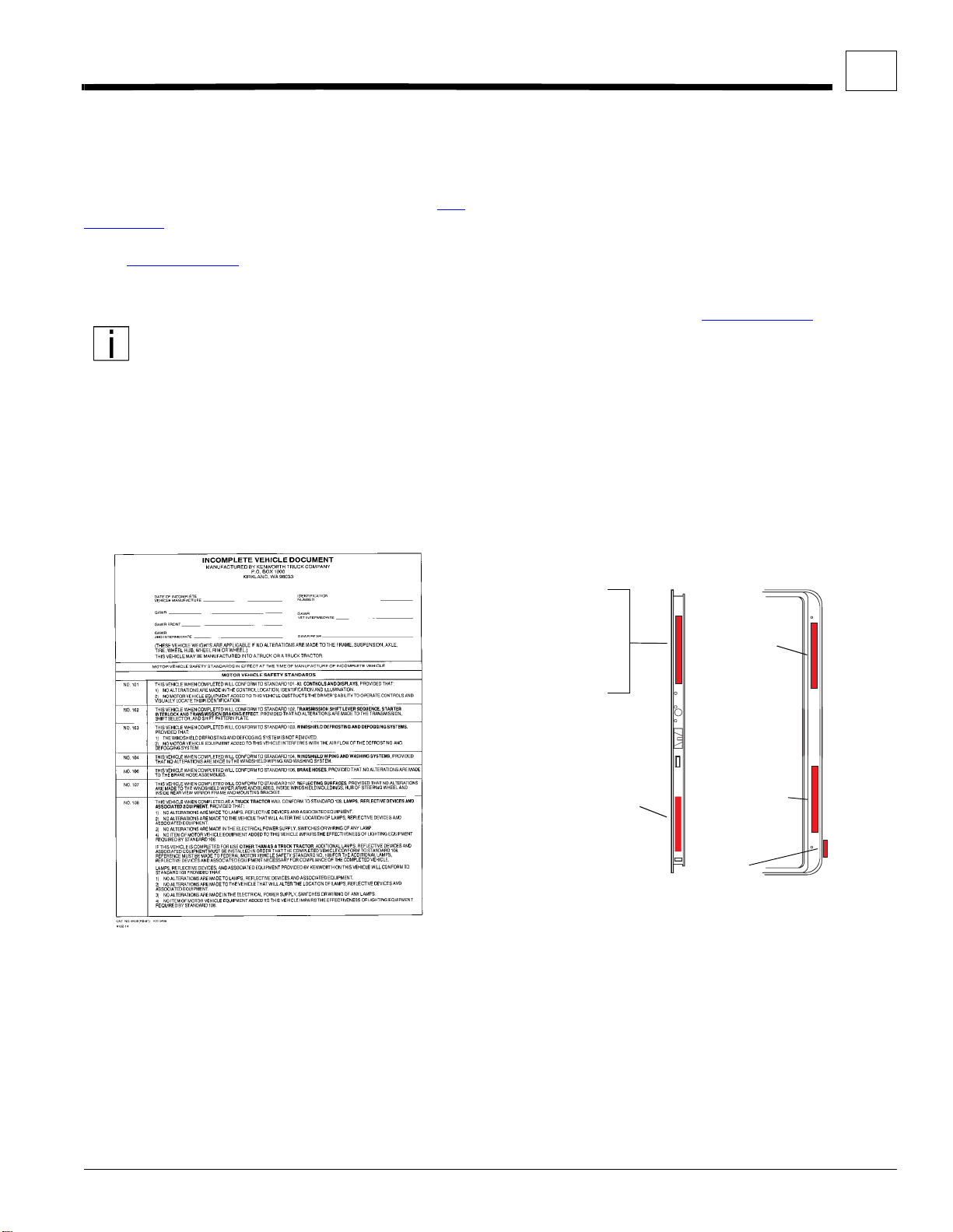
Figure 2–1. Incomplete Vehicle Certification Document. . . . . . . . . . . . . . . . . . . . . . . . . . . . . . . . . . . . . . . . . . . . . 2-2
Figure 2–2. Location of Certification Labels - Driver’s Door . . . . . . . . . . . . . . . . . . . . . . . . . . . . . . . . . . . . . . . . . . 2-2
Figure 3–1. T300 W/ Single Rear Axle: Height and Length Measurements. . . . . . . . . . . . . . . . . . . . . . . . . . . . . .3-2
Figure 3–2. T300 W/ Tandem Rear Axle: Height and Length Measurements. . . . . . . . . . . . . . . . . . . . . . . . . . . . . 3-3
Figure 3–3. T300 Front View: Width and Ground Clearance Measurements [inches (mm)]. . . . . . . . . . . . . . . . . .3-4
Figure 3–4. T300 Rear View: Width and Ground Clearance Measurements [inches (mm)]. . . . . . . . . . . . . . . . . .3-4
Figure 3–5. T300 Detailed Side View: Specific Measurements [inches (mm)]. . . . . . . . . . . . . . . . . . . . . . . . . . . .3-5
Figure 3–6. T300 Battery Box Step and Cab Floor: side view, left side. . . . . . . . . . . . . . . . . . . . . . . . . . . . . . . . . 3-6
Figure 3–7. T300 Fuel Tank Step and Cab Floor: side view, right side. . . . . . . . . . . . . . . . . . . . . . . . . . . . . . . . . . 3-7
Figure 3–8. T300 Crossmember Location and Overall Width with Doors Open. . . . . . . . . . . . . . . . . . . . . . . . . . . 3-8
Figure 3–9. T300 Fuel Tank Locations. . . . . . . . . . . . . . . . . . . . . . . . . . . . . . . . . . . . . . . . . . . . . . . . . . . . . . . . . .3-9
Figure 3–10. T300 10.5 and 10.62–Inch Rail Measurements [Inches (mm)] and Strength Characteristics. . . . . . 3-10
Figure 3–11. T300 Battery Box and Air Tank Measurements [Inches (mm)]. . . . . . . . . . . . . . . . . . . . . . . . . . . . . 3-10
Figure 3–12. T300 Standard Fuel Tank and Exhaust Measurements [Inches (mm)]. . . . . . . . . . . . . . . . . . . . . . . 3-11
Figure 3–13. T300 Optional 22-inch Fuel Tank Mounting Measurements [Inches (mm)]. . . . . . . . . . . . . . . . . . . . 3-11
Figure 3–14. T300 Vertical Tailpipe on Side of Cab [Inches (mm)]. . . . . . . . . . . . . . . . . . . . . . . . . . . . . . . . . . . . .3-12
Figure 3–15. T300 Vertical Tailpipe on Back of Cab [Inches (mm)]. . . . . . . . . . . . . . . . . . . . . . . . . . . . . . . . . . . . 3-12
Figure 4–1. Minimum Clearance Between Top of Rear Tires and Body Structure Overhang. . . . . . . . . . . . . . . . .4-1
Figure 4–2. Minimum Back–of–Cab Clearance. . . . . . . . . . . . . . . . . . . . . . . . . . . . . . . . . . . . . . . . . . . . . . . . . . . . 4-1
Figure 4–3. Air Gap with Frame Rail with Outsert . . . . . . . . . . . . . . . . . . . . . . . . . . . . . . . . . . . . . . . . . . . . . . . . .4-2
Figure 4–4. Spacer Between Frame Sill and Body Rail — Rubber or Plastic. . . . . . . . . . . . . . . . . . . . . . . . . . . . . 4-3
Figure 4–5. High Compression Spring Between the Mounting Bolt and Upper Bracket. . . . . . . . . . . . . . . . . . . . .4-3
Figure 4–6. Rubber Spacer Between Brackets. . . . . . . . . . . . . . . . . . . . . . . . . . . . . . . . . . . . . . . . . . . . . . . . . . . . 4-3
Figure 4–7. Hole Location Guidelines for Frame Rail and Bracket. . . . . . . . . . . . . . . . . . . . . . . . . . . . . . . . . . . . .4-3
Figure 4–8. Crossmember–Gusset Hole Pattern Requirements. . . . . . . . . . . . . . . . . . . . . . . . . . . . . . . . . . . . . . .4-4
Figure 4–9. Acceptable U–Bolt Mounting with Wood and Fabricated Spacers. . . . . . . . . . . . . . . . . . . . . . . . . . . . 4-5
Figure 4–10. Clearance Space for Air Lines and Cables. . . . . . . . . . . . . . . . . . . . . . . . . . . . . . . . . . . . . . . . . . . . .4-5
Figure 4–11. Example of Fishplate Bracket at Rear End of Body, used with U–Bolts. . . . . . . . . . . . . . . . . . . . . . . 4-5
Figure 5–1. Detail of Frame Extensions and Joint Welding. . . . . . . . . . . . . . . . . . . . . . . . . . . . . . . . . . . . . . . . . . . 5 -2
Figure 5–2. Frame Insert . . . . . . . . . . . . . . . . . . . . . . . . . . . . . . . . . . . . . . . . . . . . . . . . . . . . . . . . . . . . . . . . . . . .5-2
Figure 5–3. Comparison of Original, Shortened, and Extended Wheelbases. . . . . . . . . . . . . . . . . . . . . . . . . . . . . 5-3
Figure 5–4. Crossmember Added When Distance Exceeds 60 Inches (1524mm). . . . . . . . . . . . . . . . . . . . . . . . .5-4
Figure 6–1. Location of Prewired Body Harness Connection. . . . . . . . . . . . . . . . . . . . . . . . . . . . . . . . . . . . . . . . .6-1
Figure 6–2. Prewired Truck and Body Harness (before 4/98) . . . . . . . . . . . . . . . . . . . . . . . . . . . . . . . . . . . . . . . . 6-2
Figure 6–3. Prewired Truck and Body Harness (after 3/98) . . . . . . . . . . . . . . . . . . . . . . . . . . . . . . . . . . . . . . . . . . 6-3
Figure 6–4. Adding a Third Battery . . . . . . . . . . . . . . . . . . . . . . . . . . . . . . . . . . . . . . . . . . . . . . . . . . . . . . . . . . . . . 6-5
Figure 6–5. Liftgate Circuit Breaker Inside Battery Box. . . . . . . . . . . . . . . . . . . . . . . . . . . . . . . . . . . . . . . . . . . . . . 6-6
Figure A–1. Vehicle Identification Number (VIN). . . . . . . . . . . . . . . . . . . . . . . . . . . . . . . . . . . . . . . . . . . . . . . . . . .A-1
Figure A–2. Driver’s Door and Door Frame Labels . . . . . . . . . . . . . . . . . . . . . . . . . . . . . . . . . . . . . . . . . . . . . . . . .A-1
Figure A–3. Cummins Identification Plate. . . . . . . . . . . . . . . . . . . . . . . . . . . . . . . . . . . . . . . . . . . . . . . . . . . . . . . .A-2
Figure A–4. Front Axle Identification. . . . . . . . . . . . . . . . . . . . . . . . . . . . . . . . . . . . . . . . . . . . . . . . . . . . . . . . . . . .A-2
Figure A–5. Rear Axle Identification Labels. . . . . . . . . . . . . . . . . . . . . . . . . . . . . . . . . . . . . . . . . . . . . . . . . . . . . . .A-3
Figure B–1. Balanced Load: CGf 100 in. from front axle. . . . . . . . . . . . . . . . . . . . . . . . . . . . . . . . . . . . . . . . . . . . .B-2
Figure B–2. Unbalanced Load: CGf 133 in. from front axle. . . . . . . . . . . . . . . . . . . . . . . . . . . . . . . . . . . . . . . . . . .B-2
Figure B–3. Balanced Body Unloaded: CGf 156 in. (3962 mm) from front axle. . . . . . . . . . . . . . . . . . . . . . . . . . .B-5
Figure B–4. Liftgate Example: CGf 246 in. (6248 mm) from front axle. . . . . . . . . . . . . . . . . . . . . . . . . . . . . . . . . .B-6
Figure B–5. Loaded Vehicle Example: CGf 156 in. (3962 mm) from front axle. . . . . . . . . . . . . . . . . . . . . . . . . . . .B-7
Kenwo rth Truck Co. 6/99 IV

CONTENTS
TABLES
TABLE 3-1. Abbreviations Used. . . . . . . . . . . . . . . . . . . . . . . . . . . . . . . . . . . . . . . . . . . . . . . . . . . . . . . . . . . . . . . . . . .3-1
TABLE 3-2. Turning Radius-T300 w/single rear axle . . . . . . . . . . . . . . . . . . . . . . . . . . . . . . . . . . . . . . . . . . . . . . . . . . .3-1
TABLE 3-3. Turning Radius-T300 w/tandem rear axles . . . . . . . . . . . . . . . . . . . . . . . . . . . . . . . . . . . . . . . . . . . . . . . . .3-1
TABLE 3-4. T300 w/ Single Rear Axle: Overall Dimensions [inches (mm)]. . . . . . . . . . . . . . . . . . . . . . . . . . . . . . . . . . .3-2
TABLE 3-5. T300 w/ Tandem Rear Axle: Overall Dimensions [inches (mm)]. . . . . . . . . . . . . . . . . . . . . . . . . . . . . . . . .3-3
TABLE 3-6. T300 Front and Rear Suspension (FS/RS) Centerline (C/L) to Rail Measurements. . . . . . . . . . . . . . . . . . 3-5
TABLE 3-7. T300 Battery Box Step and Cab Floor Measurements. . . . . . . . . . . . . . . . . . . . . . . . . . . . . . . . . . . . . . . .3-6
TABLE 3-8. T300 Fuel Tank Step and Cab Floor Measurements. . . . . . . . . . . . . . . . . . . . . . . . . . . . . . . . . . . . . . . . . .3-7
TABLE 3-9. T300 Crossmember Locations: measured from front axle centerline [inches (mm)]. . . . . . . . . . . . . . . . . .3-8
TABLE 3-10.T300 Fuel Tank Locations for Standard Wheelbase Configurations [inches (mm)]. . . . . . . . . . . . . . . . . . .3-9
TABLE 6-1. Third Battery Installation Parts . . . . . . . . . . . . . . . . . . . . . . . . . . . . . . . . . . . . . . . . . . . . . . . . . . . . . . . . . .6-5
TABLE A-1. Model Year Letter (CODE) Designations. . . . . . . . . . . . . . . . . . . . . . . . . . . . . . . . . . . . . . . . . . . . . . . . . . .A-1
TABLE B-1. T300 Single Rear Axle “Bare” Chassis Tare Weights (no driver, no fuel), lb (kg). . . . . . . . . . . . . . . . . . . .B-3
TABLE B-2. T300 Tandem Rear Axle “Bare” Chassis Tare Weights (no driver, no fuel), lb (kg). . . . . . . . . . . . . . . . . . .B-4
TABLE B-3. T300 Options . . . . . . . . . . . . . . . . . . . . . . . . . . . . . . . . . . . . . . . . . . . . . . . . . . . . . . . . . . . . . . . . . . . . . . .B-4
TABLE B-4. T300 Weight distribution and chassis rating calculation (sample) . . . . . . . . . . . . . . . . . . . . . . . . . . . . . . .B-7
TABLE B-5. Recommended T300 Body Lengths (Single Rear Axle). . . . . . . . . . . . . . . . . . . . . . . . . . . . . . . . . . . . . . .B-8
TABLE B-6. Recommended T300 Body Lengths (Tandem Rear Axle). . . . . . . . . . . . . . . . . . . . . . . . . . . . . . . . . . . . . .B-8
Kenwo rth Truck Co. 6/99 V
SECTION 1 INTRODUCTION
SCOPE
This manual was created to provide body builders with
appropriate information and guidelines useful in the
body planning and installation process. This information
will be helpful when installing bodies or other associated equipment.
This manual contains appropriate dime nsional information, guidelines for mounting bodies, guidelines for
modifying frames, electrical wiring information, and
other information useful in the body installation process.
The intended primary users of this manual are body
builders who install bodies and associated equipment
on Kenworth T300 Medium Duty vehicles. Dealers who
sell and service the vehicle will also find this information
useful.
This Body Builders’ Manual can be very useful when
specifying a vehicle, particularly when th e body builder
is involved in the vehicle definition and ordering pro-
cess. Early in the process, professional body builders
can often contribute valuable information that reduces
the ultimate cost of the body installation.
This manual is not a maintenance manual or an
operation manual.
• For chassis maintenance and repair information
consult the
Manual
selling dealer or you can order your own copy of the
maintenance manual from your local dealer.
• For chassis operating information consult the
ator’s Manual
also be ordered from your local dealer.
Kenworth Medium Duty Maintenance
available in the Service Departmen t of the
Oper-
, included with each vehicle. They can
1–1 6/99 Body Builders’ Ma nual
SECTION 2 SAFETY AND COMPLIANCE
SAFETY SIGNALS
We’ve put a number of alerting mess ages in this book.
Please read and follow them. They are there for your
protection and information. These alerting messages
can help you avoid injury to yourself or others and help
prevent costly damage to the vehicle.
Key symbols and “signal words” are used to indicate
what kind of message is going to follow. Pay special
attention to comments prefaced by “WARNING”, “CAUTION”, and “NOTE.” Please don't ignore any of these
alerts.
Warnings, cautions, and notes
WARNING
When you see th is word and symbol, the message that follows is especially vital. It signals a
potent ially hazardou s situatio n which, if not
avoided, could result in death or serious injury.
This m essage wil l tell you what the haza rd is,
what can happen if you don’t heed the warning,
and how to avoid it.
Example:
WARNING! Be sure to use a circuit breaker
designed to meet liftgate am p erage req ui rements. An incorrectly specified circuit
breaker could result in a electrical overload
or fire situation. Follow the liftgate installation instructions and use a circuit breaker
with the recommeded capacity.
CAUTIO N
Signals a potentially hazardous situation
which, if not avoi ded, could r esult i n minor or moderate injury or damage to the vehicle.
Example:
CAUTION:
in the rail. Use the appropriate drill bit.
Never use a torch to m ake a h ole
NOTE
Provides general infor mation: for example, the
note could warn you on how to avoid damaging
your vehicle or how to drive the vehicle more efficiently.
Example:
NOTE:
to the battery box and fuel tank fill neck.
Please take the time to read these mes-
sages when you see them, and remember:
WARNING
Indicates a potentially hazardous situation
which, if not avoided, could result in death or
seri o us inj u ry.
CAUTION
Signals a potentially hazardous situation which,
if not avoided, could result in minor or moderate
injury or damage to the vehicle.
NOTE
Useful information that is related to the topic
being discussed.
Be sure to provide maintenanc e access
FEDERAL MOT OR VEHICLE SAFETY STANDARDS (FMVSS) COMPLIANCE
As an Original Equipment Manufacturer (OEM), Kenworth Truck Co. ensures that our products comply with
all applicable Federal Motor Vehicle Safety Standards
(FMVSS). However, the fact that this vehicle has no
fifth–wheel and that a Body Builder (Final Stage M anufacturer) will be doing additional modifications means
that the vehicle was incomplete when it left the build
plant. See page 2–2
information.
and Appendix A for additional
Kenwo rth Truck Co. 6/99 2–1
SAFETY AND COMPLIANCE
Figure 2–1. Inco mp le te Vehicle Ce rtifica tion
Document.
01476
2
Incomplete Vehicle Certification
An Incomplete Vehicle Document is shipped with the
vehicle, certifying that the vehicle is no t complete. Se e
Figure 2–1. In addition, affixed to th e driver's side d oor
frame or edge is an Incomplete Vehicle Certification
label. See Figure 2–2.
cle Certification and Identification, see APPENDIX A
“VEHICLE IDENTIFICATION.”
NOTE: These documents list the FMVSS regulations that the vehicle complied with when it
left the build plant. You should be aware that if
you modify or alter any of the components or
systems covered by these FMVSS regulations, it is your responsibility as the Final
Stage Manufacturer to ensure that the complete vehicle maintains compliance with the
particular FMVSS regulations whe n you complete your modifications.
. For further information on Vehi-
As the Final Stage Manufacturer, you should retain the
Incomplete Vehicle Document for your records. In addition, you should record and retain the manufacturer and
serial number of the tires on the vehicle. Upon completion of the vehicle (installation of the body and any other
modifications), you should affix your certification label
to the vehicle as required by Federal law. This tag identifies you as the “Final Stage Manufacturer” and certifies that the vehicle complies with Federal Motor
Vehicle Safety Standards. (See Figure 2–2.
DOOR EDGE
DOOR
)
FRAME
TIRE,RIM,CERTIFICATION
AND WEIGHT LABEL
(TRACTOR)
OR INCOMPLETE
VEHICLE
CERTIFICATION
LABEL (TRUCK)
MAJOR
COMPONENTS
AND WEIGHTS
LABEL (TRUCK
OR TRACTOR)
FINAL STAGE MAN-
UFA CTURER LABEL
(STAMPED)
Figure 2–2. Location of Certification
Labels - Driver’s Door
TIRE, RIM,
AND WEIGHT
RATING DATA
LABEL
(TRUCK)
(TO BE INSTALLED
BY FINAL STAGE
MANUFACTURER
(TRUCK ONLY)
CHASSIS
NUMBER
02378
Kenwo rth Truck Co. 6/99 2–2

SECTION 3 DIMENSIONS
ABBREVIATIONS
Throughout this section and in other sections as well,
abbreviations are used to describe cer tain characteristics on your vehicle. The char t below lists the abbreviated terms used.
T ABLE 3-1. Abbreviation s Used.
A OVERALL VEHIC LE LENGTH
AF
B
CA BACK OF CAB TO REAR AXLE LENGTH
D CAB HEIGHT
WB WHEELBASE LENGTH
FRAME RAIL OVERHANG LENGTH
BEHIND REAR AXLE
FRONT BUMPER TO FRONT AXLE
LENGTH
TURNING RADIUS
Approximate turning radius specifications for the T300
are listed (by wheelbase) in the following tables. Tables
3-2 and 3-3 list turn radius information for chassis with
standard components. Optional components may give
different results.
T ABLE 3-2.
T300 W/SINGLE REAR AXLE
WHEELBASE
Turning Radius-T300 w/single rear axle
CURB TO
(IN.)
145 20 23
150 21 24
160 22 25
185 25 28
200 27 30
215 29 32
230 31 34
245 32 35
260 34 37
280 36 39
CURB (FT.)
WALL T O W ALL
(FT.)
T ABLE 3-3. Turning Radius-T300 w/tandem rear
axles
T300 W/TANDEM REAR AXLES
WHEELBASE
(IN.)
165 24 28
175 26 29
190 27 30
205 29 32
220 31 34
235 33 36
250 35 38
260 36 39
CURB TO
CURB (FT.)
WALL T O W ALL
(FT.)
OVERALL DIMENSIONS
This section includes drawings and char ts of the standard T300 vehicle, including a 10,000 lb. front suspension, a 20,000 lb. rear suspension, and R250F
295/75R22.5 tires. Use these drawings to plan overall
vehicle configurations.
On the pages t hat follow, detail drawings show particular views of each vehicle component. They illustrate
important m easurements critica l to designing bodies of
all types. See the “Contents” at the beginning of the
manual to locate the drawing you need.
Kenwo rth Truck Co. 3–1
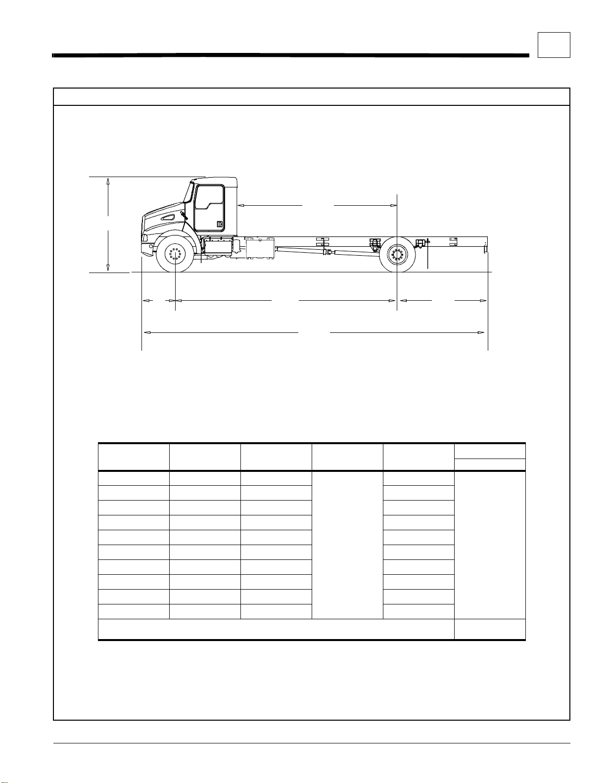
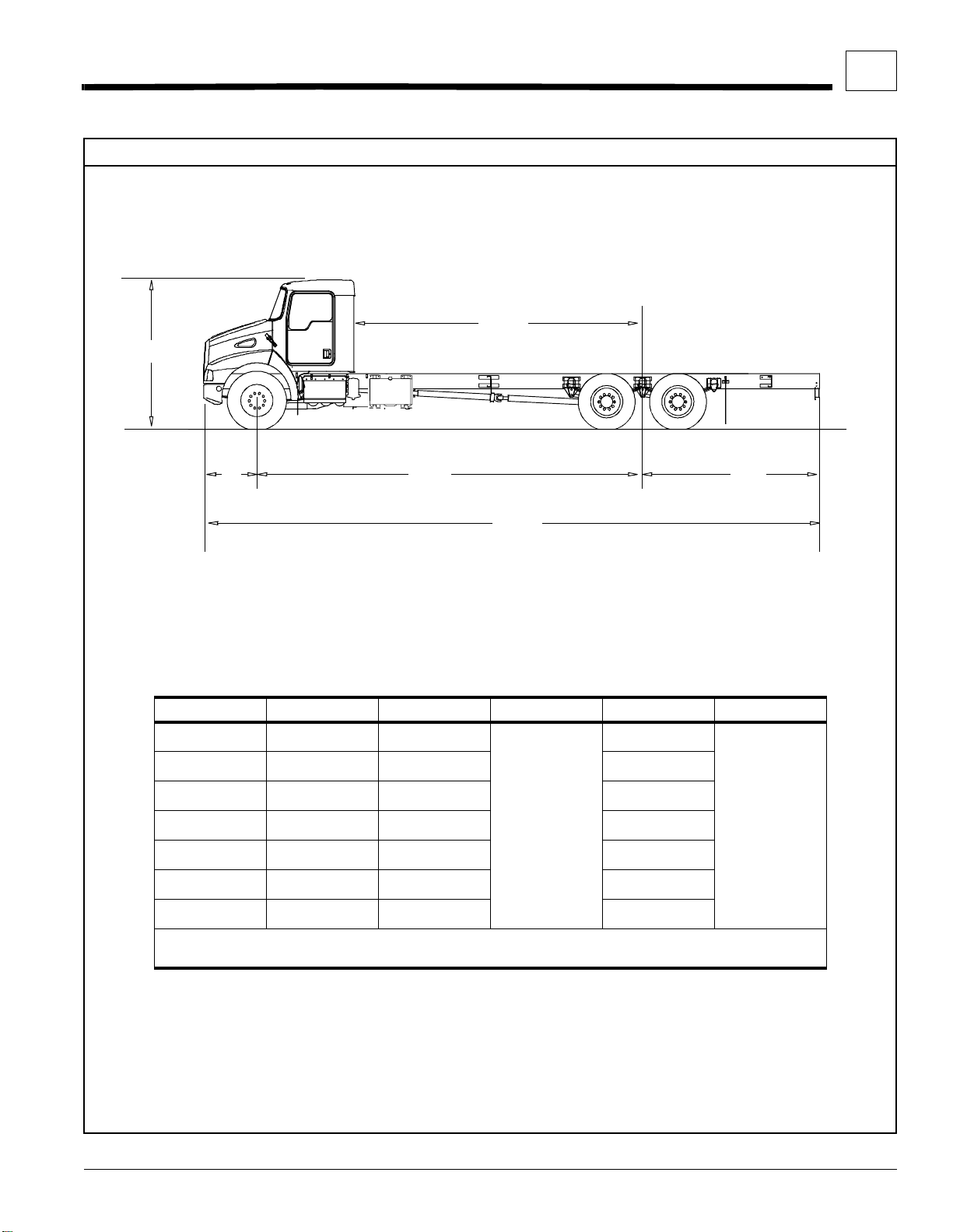
Side View — T300 with Single Rear Axle
D
CA
DIMENSIONS
OVERALL DIMENSIONS — T300
3
B
WB
A
Figure 3–1. T300 W/ Single Rear Axle: Height and Length Measurements.
T ABLE 3-4. T300 w/ Single Rear Axle: Overall Dimensions [inches (mm)].
WB A AF B CA *
145 (3683) 237.2 (6025) 55 (1397)
150 (3810) 237.2 (6025) 50 (1270) 82 (2083)
160 (4064) 261.2 (6634) 64 (1626) 92 (2337)
185 (4699) 285.2 (7244) 63 (1600) 117 (2972)
200 (5080) 309.2 (7854) 72 (1829) 132 (3353)
215 (5461) 333.2 (8463) 81 (2057) 147 (3734)
230 (5842) 357.2 (9073) 90 (2286) 162 (4115)
245 (6223) 381.2 (9682) 99 (2515) 177 (4496)
260 (6604 ) 405.2 (10292) 108 (2743 ) 192 (4877 )
280 (7112 ) 429.2 (10902) 112 (2845 ) 212 (5385 )
*
CA measured from true back of cab to rear axle centerline
** Determined with Front Tire Bridgestone R250F 295/75R22.5
37.2 (945)
AF
03008
UNLADEN
D **
77 (1956)
104.9 (26 64)
Kenwo rth Truck Co. 3–2
Side View — T300 with Tandem Rear Axle
D
CA
DIMENSIONS
OVERALL DIMENSIONS — T300
3
B
WB
A
Figure 3–2. T300 W/ Tandem Rear Axle: Height and Length Measurements.
T ABLE 3-5. T300 w/ Tandem Rear Axle: Overall Dimensions [inches (mm)].
WB A AF B CA * D **
175 (4445) 283.2 (7193) 71 (1803)
190 (4826) 307.2 (7803) 80 (2032) 122 (3099)
205 (5207) 331.2 (8412) 89 (2261) 137 (3480)
220 (5588) 355.2 (9022) 98 (2489) 152 (3861)
235 (5969 ) 379.2 (96 32) 107 (2718) 167 (4242)
250 (6350 ) 403.2 (10241) 116 (2946 ) 182 (4623 )
260 (6604 ) 427.2 (10851) 130 (3302 ) 192 (4877 )
*
CA measured from true back of cab to rear axle centerline
** Determined with Front Tire Bridgestone R250F 295/75R22.5
37.2 (945)
AF
03008T
107 (2718 )
104.9 (26 64)
Kenwo rth Truck Co. 3–3
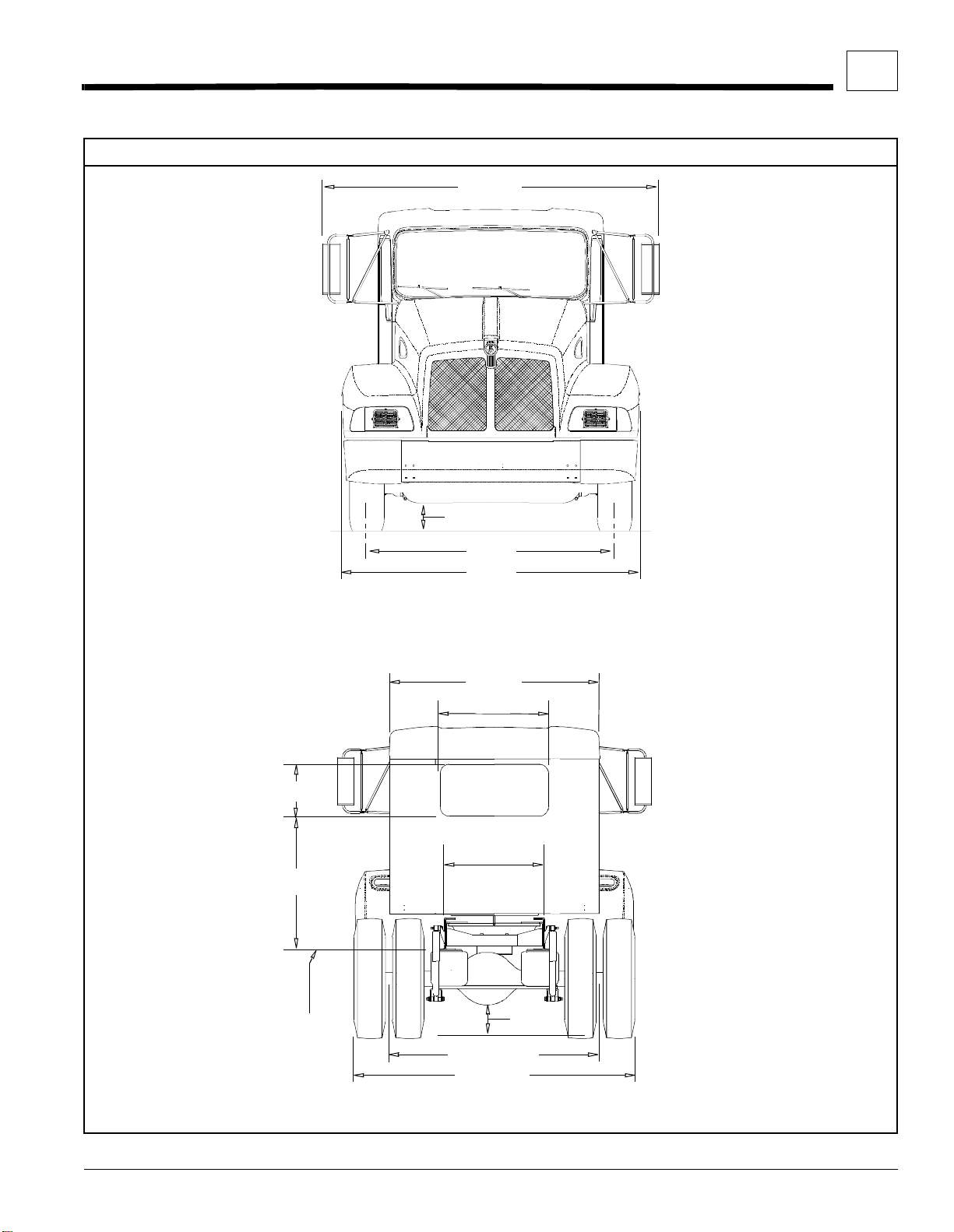
Front and Rear Views — T300
107.7
(2735)
DIMENSIONS
OVERALL DIMENSIONS — T300
3
8.9
(226)
79.1
(2019)
95.3
(2421)
Figure 3–3. T300 Front View: Width and Ground Clearance Measurements [inches (mm)].
71.8
(1824)
36
(914)
17 (432)
34
46.3 (1177)
(864)
02389
BOTTOM
FRAME
FLANGE
Figure 3–4. T300 Rear View: Width and Ground Clearance Measurements [inches (mm)].
Kenwo rth Truck Co. 3–4
71.9 (1827)
96 (2440)
9.7
(248)
03005A
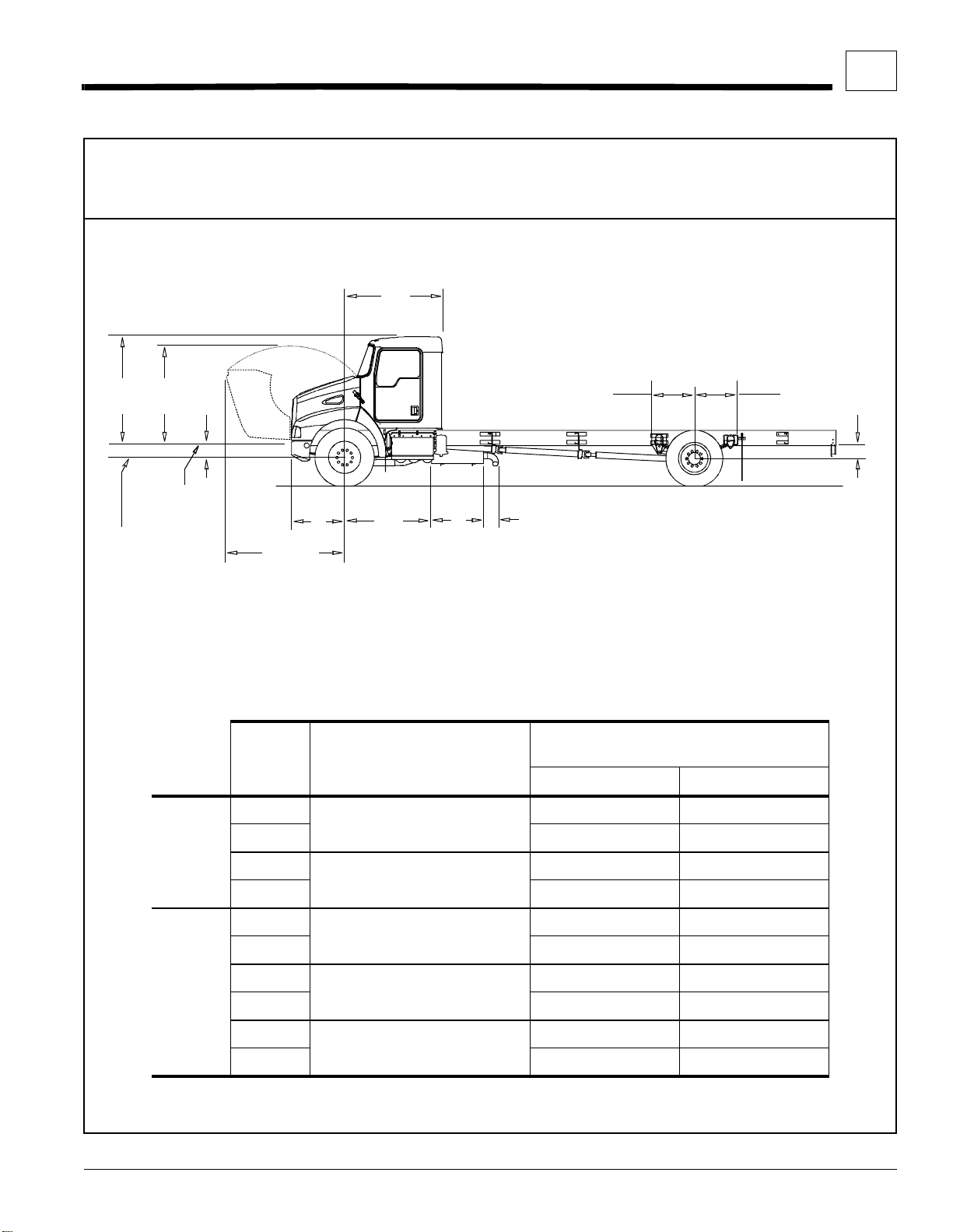
Side View Detail — T300
76.7
(1948)
66.9
(1699)
FS RS
DETAI L VI EWS
68
(1727)
DIMENSIONS
OVERALL DIMENSIONS — T300
29.8
(757)
(762)
3
30
BOTTOM
FLANGE
AXLE C / L
Figure 3–5. T300 Detailed Side View: Specific Measurements [inches (mm)].
T ABLE 3-6. T300 Front and Rear Suspension (FS/RS) Centerline (C/L) to Rail Measurements.
LOAD REAR SUSPENSION
UNLADEN
LADEN 6.6 (168) 6.6 (168)
SINGLE
UNLADEN
REAR AXLE
LADEN 6.6 (168) 7.8 (198)
UNLADEN
LADEN 6.6 (168) 7.2 (183)
37.2
(945)
82.8
(2102)
REYCO 79KB
HENDRICKSON
HAS 210L /230L
REYCO 102
61
(1550)
36
(914)
10.5
(267)
CENTERLINE OF AXLE TO BOTTOM
03008
FLANGE OF RAIL [IN. (MM)]
FS RS
8.4 (213) 9.0 (229)
8.4 (213) 7.8 (198)
8.4 (213) 8.5 (216)
UNLADEN
TANDEM
Kenwo rth Truck Co. 3–5
LADEN 6.6 (168) 7.8 (198)
REAR AXLE
UNLADEN
LADEN 6.6 (168) 7.6 (193)
HENDRICKSON
HAS 402
HENDRICKSON
RT2-400
8.4 (213) 7.8 (198)
8.4 (213) 8.6 (218)
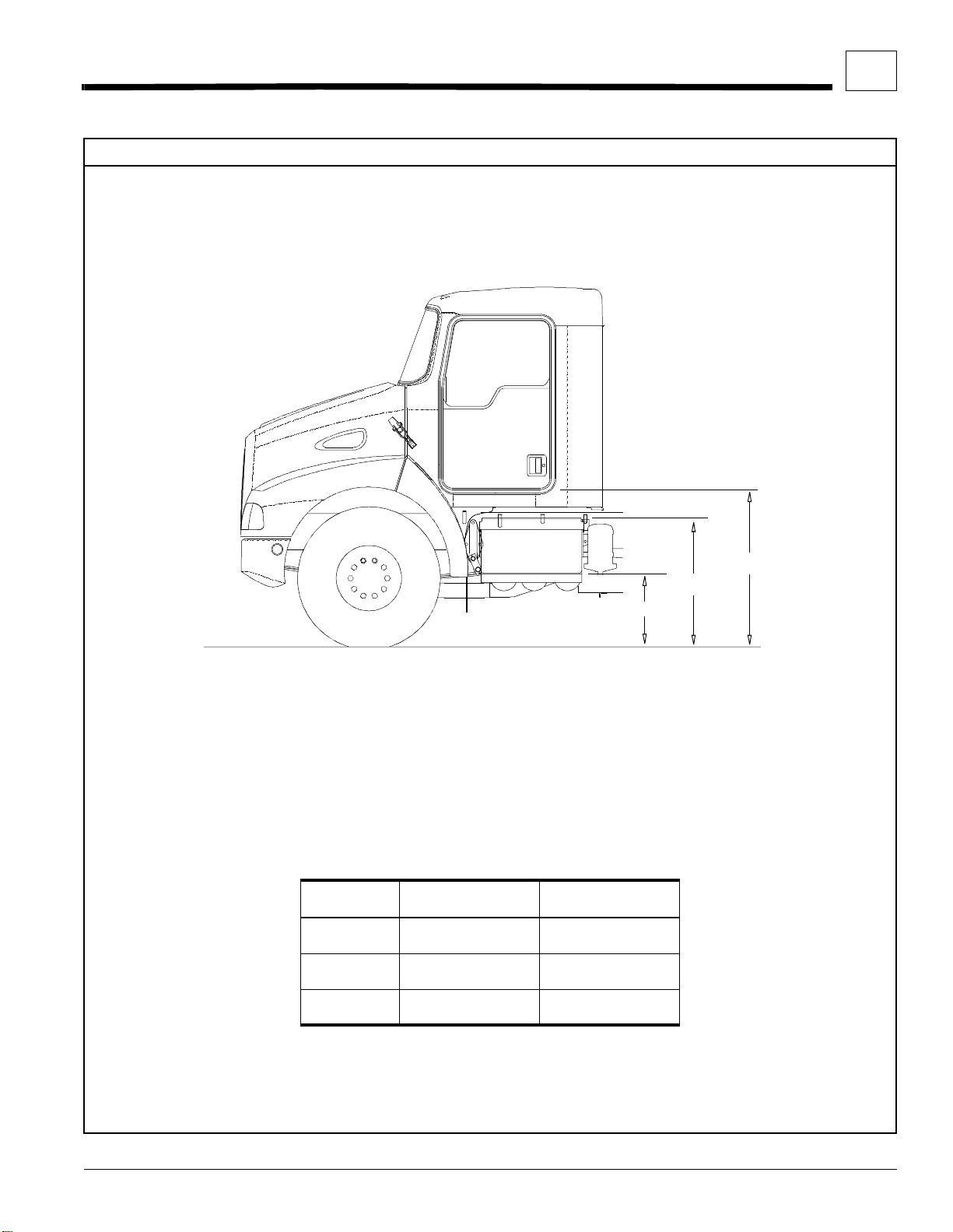
Left Side: Step and Ca b Floor Height — T300
DIMENSIONS
OVERALL DIMENSIONS — T300
3
Figure 3–6. T300 Battery Box Step and Cab Floor: side view, left side.
T ABLE 3-7. T300 Battery Box Step and Cab Floor Measurements.
POSITION
A FIRST
STEP
B SECOND
STEP
C CAB
FLOOR
UNLADEN
IN. (MM)
21.3 (540) 18.9 (481)
37.0 (940) 34.7 (881)
44.6 (1133) 42 (1069)
LADEN
IN. (MM)
C
B
A
03012
Kenwo rth Truck Co. 3–6

Right Side: Step and Cab Floor Height — T300
DIMENSIONS
OVERALL DIMENSIONS — T300
3
C
B
A
Figure 3–7. T300 Fuel Tank Step and Cab Floor: side view, right side.
T ABLE 3-8. T300 Fuel Tank Step and Cab Floor Measurements.
POSITION
A FIRST
STEP
B SECOND
STEP
C CAB
FLOOR
UNLADEN
IN. (MM)
23.3 (592) 21.0 (533)
38.1 (967) 35.8 (908)
44.6 (1133) 42 (1069)
9707211
LADEN
IN. (MM)
Kenwo rth Truck Co. 3–7

Crossmember Locations — T300
118
(2997)
50°–55°
A
B
DIMENSIONS
OVERALL DIMENSIONS — T300
3
C
D
E
Figure 3–8. T300 Crossmember Location and Overall Width with Doors Open.
TABLE 3-9. T300 Crossmember Locations: measured from front axle centerline [inches (mm)].
WHEELBASE A CB B CB C CB D E
145
146 - 150
151 - 160
161 - 185
186 - 200
201 - 215
216 - 230
231 - 245
246 - 260
261 - 280
157 - 177
178 - 193
194 - 217
218 - 231
232 - 247
248 - 256
257 - 262
90.7 (2305)
79.7 (2025)
90.7 (2305)
101.7 (2585)
101.7 (2585)
90.7 (2305)
101.7 (2585)
101.7 (2585)
101.7 (2585)
101.7 (2585)
90.7 (2305)
90.7 (2305)
101.7 (2585)
101.7 (2585)
90.7 (2305)
101.7 (2585)
101.7 (2585)
✓ Driveline centerbearing (CB) mounted on this crossmember
➀ Dimensions noted are based on the use of the standard T300 transmission, rear axle, and driveline.
— ➀ ————— —
✓ ➀ ————— —
✓ ————— —
✓ ————— —
—
✓
✓
✓
✓
✓
140.3 (3565)
118.3 (3005)
162.4 (4125)
162.4 (4125)
162.4 (4125)
140.3 (3565)
———— —
✓
156.9 (3985)
✓ ———
✓ ———
✓
—
201 (5105)
178.9 (4545)
——
——
✓
217.5 (5525) 344.4 (8748)
279.4 (7097)
294.4 (7478)
309.4 (7859)
324.4 (8240)
T ANDEM REAR AXLES
—————— —
✓ ————— —
✓ ————— —
—
✓
✓
✓
140.3 (3565)
118.3 (3005)
151.4 (3845)
156.9 (3985)
———— —
✓
156.9 (3985)
✓ ———
✓ ———
——
325.4 (8265)
340.4 (8646)
350.4 (8900)
03009
Kenwo rth Truck Co. 3–8

Fuel Tank Locations — T300
A B
A
DIMENSIONS
OVERALL DIMENSIONS — T300
3
Figure 3–9. T300 Fuel Tank Locations.
TABLE 3-10. T300 Fuel Tank Locations for Standard Wheelbase Configurations [inches (mm)].
FUEL T ANK A * B
RH Under Cab
Rectangular Steel 50 Gal
Round 22” Aluminum
LH Behind Cab
Rectangular Steel
Round 22” Aluminum **
* Measured from centerline of front axle
** Also RH Behind Cab.
B
56 Gal 35.6 (904)
75 Gal 47.3 (1201)
100 Gal 62.2 (15 80)
120 Gal 74.3 (18 87)
50 Gal 78.3 (1989) 30.5 (775)
70 Gal 77.7 (1974) 42.6 (1082)
56 Gal
75 Gal 47.3 (1201)
100 Gal 62.2 (15 80)
32.8 (833)
77.3 (1963)
03011
33.5 (851)
35.6 (904)
Kenwo rth Truck Co. 3–9

Frame Rail Configurations — T300
COMPONENTS
DIMENSIONS
OVERALL DIMENSIONS — T300
3
10.5–INCH RAIL
YIELD: 80,000 psi
SECTION MODULUS:
16.75 cu in.
RBM: 1,340,000 lb. in.
01162-1
.5
(12.7)
10.5
(266.7)
.25
(6.35)
Figure 3–10. T300 10.5 and 10.62–Inch Rail Measurements
10
(254)
3.5
(88.9)
[Inches (mm)] and Strength Characteristics.
Battery Box and Air Tanks — T300
10.62–INCH RAIL
3.74
HEAT TREATED
(95)
YIELD: 110,00 0 ps i
SECTION MODULUS:
14.8 cu in.
10.24
(260)
ST ANDARD BATTER Y
BOX WITH AIR TANKS
RBM: 1,628,000 lb. in.
.25
(6.35)
.31
(7.94)
3.46
(87.8)
10
(254)
10.62
(269.9)
01161-1
33
(838)
8.7
(220)
7.2
12.6
(319)
Figure 3–11. T300 Battery Box and Air Tank Measurements
Kenwo rth Truck Co. 3–10
(184)
REAR VIEW
[Inches (mm)].
13.6 (346)
15.9 (404) UNLADEN
GROUND
LADEN
03006-1

Fuel Tank and Exhaust — T300
DIMENSIONS
OVERALL DIMENSIONS — T300
3
03006-2
13.2
(334)
(44)
STANDARD FUEL TANK MOUNTING
26.2
(665)
1.8
23
(583)
REAR VIEW
Figure 3–12. T300 Standard Fuel Tank and Exhaust
EXHAUST / MUFFLER MOUNTING
2.5
(63)
6.8
(172)
13.0 (331) LADEN
15.3 (389) UNLADEN
GROUND
Meas u remen t s [Inche s (mm)] .
HORIZONTAL
FROM OUTSIDE
OF RAIL
1.3
(32)
12.2
(309)
REAR VIEW
13.8
(351)
FROM OUTSIDE
OF RAIL
03007
22-inch Fuel Tanks — T300
REAR VIEW
Figure 3–13. T300 Optional 22-inch Fuel Tank Mounting Measurement s [I nches (mm)].
11.0
(279)
16.3
(414)
9.9 (251) LADEN
12.2 (310) UNLADEN
GROUND
25.9
(658)
REAR VIEW
RIGHT SIDE UNDER CABLEFT SIDE BEHIND CAB
Kenwo rth Truck Co. 3–11

Horizontal Muffler-Vertical Tailpipe on Cab — T300
7.3 (185)
7 (178)
DIMENSIONS
OVERALL DIMENSIONS — T300
3
Figure 3–14. T300 Vertical Tailpipe on Side of Cab [Inches (mm)].
CENTERLINE OF CAB
25 (635)
MUFFLER
8 (203)
29
(736.6)
BACK OF CAB
Figure 3–15. T300 Vertical Tailpipe on Back of Cab [Inches (mm)].
Kenwo rth Truck Co. 3–12

SECTION 4 BOD Y MOUNTING
CRITICAL CLEARANCES
Rear Wheels and Cab
CAUTION: Insufficient clearance between
rear tires and body structure could cause
damage to the body during suspension
movement. Allow at least 8 inches clear-
ance (See Figure 4–1.)
Normal suspension movement could cause contact
between the tires and the body. To prevent this, mount
the body so that the m inimum clearance between the
top of the tire and the bottom of the body is 8 inches
(203mm). This should be measured with the body
empty. See Figure 4–1.
8 in.
(203mm)
72 in.
(1829 mm)
MINIMUM
4 in.
03008-4
Figure 4–2. Minimum Back–of–Cab Clearance.
a minimum of 4 inches (102 mm) behind the cab. The
result is a minimum back–of–cab clearance of 72
inches (1829 mm) from the front axle to the leading
edge of the body.
• See SECTION 3 “DIMENSIONS” for further
details on dimensions and clearances.
• Also, se e APPENDI X B “WEIGH T DISTRI BUTION” for explanation of back–of–cab (BOC) /
CA calculations.
02866
Figure 4–1. Minimum Clearance Between Top
of Rear Tires and Body Structure
Overhang.
CAUTION: Maintain adequate clearance
between back of cab and the front (leading
edge) of mounted body . See Figure 4–2.
NOTE: Be sure to provide maintenance
access to battery box and fuel tank fill neck.
The true distance from the centerline of the front axle to
the back of the cab is 68 inches (1727 mm). It is recommended that the leading edge of the body be mo unted
Kenwo rth Truck Co. 4–1

BODY
BODY MOUNTING
4
12.7 mm (½ in.)
GAP
OUTSERT
Figure 4–3. Air Gap with Frame Rail with Outsert
Chassis with Outserts
A 10½-inch non-heat treated frame rail with an outsert
will have an air gap of approximately 6.4 mm (¼ inch)
between the bottom of the out sert flange and the to p of
the frame rail flange. This gap is for manufacturing tolerance purposes and guarantees that the outsert will fit
over the frame rail.
WARNING! If the frame rail flanges are
modified or damaged, the rail could fail
prematurely and cause an accid ent. When
mounting a body to the chassis, DO NOT
drill holes in the upper or lower flange of
the fram e rail. Mount the body usi ng body
mounting brackets or U–bolts.
Install a 12.7 mm (½ inch) thick spacer on the frame rail
aft of the outsert to suppor t the body. The purpose of
the spacer is to fill the "gap" See Figure 4–3. above.
OUTSERT
BODY
FRAME
RAIL
BOD Y MOUNTING USING
BRACKETS
CAUTION: Always install a spacer between
the body subframe and the top flange of
the frame rail.
Installation of a spacer between the body subframe and
the top flange of the frame rail will he lp prevent premature wear of the components due t o chafing or corrosion.
Frame Sill
If the body is mounted to the frame with brackets, we
recommend that the frame sill spacer be made from a
strip of rubber or plastic (delrin or nylon). These materials will not undergo large dimensional changes during
periods of high or low humidity. The strip will be less
likely to fall out during extreme relative motion between
body and chassis. See Figure 4–4.
Kenwo rth Truck Co. 4–2

BOD Y
SUBFRAME
(RAIL)
CHASSIS FRAME
(RAIL) SILL
SPACER
Figure 4–4. Spacer Between Frame Sil l and
Body Rail — Rubber or Plastic.
01016
BODY MOUNTING
4
RUBBER
SPACER
01445
Figure 4–6. Rubber Spacer Between Brackets.
These designs will allow relative movement between
the body and t he chassis during extreme f rame racking
situations. Extreme frame racking, and mountings that
are too rigid, could caus e damage to the body. This is
particularly true with tanker installations.
Brackets
When mounting a body to the chassis with brackets, we
recommend designs that offer limited amount of relative
movement, bolted securely but not too rigid. Brackets
should allow for slight movement between the body and
the chassis. For instance, Figure 4–5 shows a high
compression spring between the bolt and the bracket.
SPRING
01446
Figure 4–5. High Compression Spring Between
the Mounting Bolt and Upper
Bracket.
Another possibility is mounting a rubber spacer
between the brackets. See Figure 4–6.
Mounting Holes
When installing the lower bracket on frame rails the
mounting holes in the chassis fram e bracket and frame
rail must comply with th e general spacing an d location
guidelines illustrated in Figure 4–7. The hole diameter
should not exceed the bolt diamet er by more than .0 60
inches (1.5mm).
A or B EQUAL TO OR GREATER THAN 2 in. (50mm)
UPPER FRAME
FLANGE
LOWER FRAME
FLANGE
01023
Figure 4–7. Hole Location Guidelines for Fr am e Rail
and Bracket.
Kenwo rth Truck Co. 4–3

BODY MOUNTING
4
4 HOLES
.5 IN. DIA.
(12.7mm)
5.63
(143mm)
2.0
(50mm)
5.5
(140mm)
Figure 4–8. Crossmember–Gusset Hole P attern Requirements.
Frame Drilling
WARNING!
chassis, DO NOT drill holes in the upper or
lower flange of th e frame rail. If the frame
rail flanges are modified or damaged, the
rail could fail prematurely and cause an
accident. Mount the body using body
mounting brackets or U–bolts.
When mounting a body to the
6 HOLES
.5 IN. DIA.
(12.7mm)
5.63
(143mm)
2.0
(50mm)
5.5
(140mm)
11.0
(279mm)
01022-01
Hole Location Guidelines
Holes must be located from th e flange as indicated in
Figure 4–7. They must be no closer than 2 inches
(50mm) to each other.
NOTE: If your design permits placement of
body mounting brackets at crossmember locations, you can use the crossmember gusset
bolt holes for body mounting. See Figure 4–8.
BODY MOUNTING USING U–BOLTS
Spacers
If the body is mounted to the frame with U–bolts, use a
hardwood sill (minimum 1/2 inch (12 mm) thick)
between the frame rail and body frame to protect the
WARNING! Do not drill new holes any
closer than 2 inches (50mm) to existing
holes. Frame drilling affects the strength of
the rails.
Kenwo rth Truck Co. 4–4
top surface of the rail flange.
CAUTION: Use care when drilling the
frame web so the wires and air lines routed
inside the rail are not damaged.

BODY MOUNTING
Figure 4–9. Acceptable U–Bolt Moun ti ng wit h Wood
and Fabricated Spacers.
BODY
STRUCTURE
TRUCK FRAME
WOOD SILL
½ in. (12mm)
U–BOLT
FRAME RAIL
SPACER
(FABRICATED
STEEL OR
HARDWOOD)
U–BOLT
SPACER
(HARDWOOD)
01018
MINIMUM
4
WARNING! Do not allow the frame rails or
flanges to deform when tightening the
U–bolts. It will weaken the frame and cou ld
cause an accident. Use suitable spacers
made of steel or hardwood on the inside of
the frame rail to prevent collapse of the
frame flanges.
• Use a hardwood spacer between the bottom
flange and the U–bolt to prevent the U–bolt
from notching the frame flange. See Figure 4–9.
FRAME
RAIL
AIR LINES
AND WIRING
HARNESSES
CHECK
CLEARANCE
SPACE FOR AIR
LINES AND
WIRING
Figure 4–10. Clearance Space for Air Lines and
Cables.
U–BOLT
FRAME RAIL
SPACER
(HARDWOOD
OR STEEL)
U–BOLT
SPACER
WARNING! Do not notch frame rail flanges
to force a U–bolt fit. Notched or damaged
frame flanges could result in premature
frame failure. Use a larger size U–bolt.
01027
WARNING! Do not allow spacers and other
body mounting parts to interfere with
brake lines, fuel lines, or wiring har nesses
routed inside the frame rail. Crimped or
damaged brake lines, fuel lines, or wiring
could result in loss of braking, fuel leaks,
electrical overload or a fire. Carefully
inspect the installation to ensure adequ ate
Kenwo rth Truck Co. 4–5
clearances for air brake lines, fuel lines,
and wiring. See Figure 4–10.
CAUTION: Mount U–bolts so they do not
chafe on frame rail.
Rear Body Mount
When U–bolts are used to mount a body we recommend that the last body attachment be made with a
“fishplate” bracket. See Figure 4–11. This provides a
firm attaching poin t and helps prevent any relative fore
or aft movement between the body and frame.
BODY
STRUCTURE
FRAME
RAIL
Figure 4–11. Example of Fishplate Br ack et at Rear End
of Body, used with U–Bolts.

SECTION 5 FRAME MODIFICATIONS
INTRODUCTION
There are ten standard wheelbase choices for the T300
with a single rear axle (145 to 280 inches) and seven
choices available with tandem rear axles. In addition,
the T300 offers customer specified wheelbases. So, in
most cases frame modifications to produce a certain
wheelbase should not be necessary.
However, some installations may require slight modifications, while other installations will require extensive
modifications. Sometimes an existing dealer stock
chassis may need to have the wheelbase changed to
better fit a customer’s application. The modifications
may be as simple as shortening or lengthening the
frame cutoff, or they may be as complex as changing
the wheelbase.
DRILLING RAILS
Location and Hole Pattern
If holes need to be drilled t o attach a nything to th e rail,
see SECTION 4 “BODY MOUNTING” for more information. Follow the general spacing and hole location
guidelines on Page 4–3, Figure 4-6.
WARNING!
chassis, DO NOT drill holes in the upper or
lower flange of th e frame rail. If the frame
rail flanges are modified or damaged, the
rail could fail prematurely and cause an
accident. Mount the body using body
mounting brackets or U–bolts.
When mounting a body to the
WARNING! Do not drill new holes any
closer than 2 inches (50mm) to existing
holes. Frame drilling affects the strength of
the rails.
CAUTION: Use care when drilling the
frame web so the wires and air lines routed
inside the rail are not damaged.
• Never use a torch to make a hole in the rail. Use
the appropriate diameter drill bit.
Hole pattern dimensions for crossmember designs are
illustrated in Page 4–3, Figure 4-7.
Hole diameter should not exceed the bolt diam eter by
more than .060 inches (1.5 mm).
MODIFYING FRAME LENGTH
The frame cutoff after the rear axle can be shortene d to
match a particular body leng th. Using a torch is acceptable; however, heat from a torch will affect the material
characteristics of the frame rail. The affected material
will normally be confined to within 1 to 2 inches (25 to
50mm) of the flame cut and may not adversely affect
the strength of the chassis or body installation.
The frame cutoff can be lengthened by adding frame
extenders.
When extending the rails, the additional sections can
typically be welded to the existing rails. The joint should
be welded and reinforced as illustrated in Figure 5–1.
NOTE: See page 5–4 for more information on
welding frames.
Frame Insert
A frame insert must be added after welding a frame rail
to compensate for lost strength. The insert should be of
the same material as the frame member, or of steel,
and at least equal to the frame rail in thickness.
Attachment of the insert to the frame should be made
with Ream-Fit heat-treated bolts, 5/8 in. (16 mm) dia. or
the next larger size. Both the reinforcement and frame
Kenwo rth Truck Co. 5–1

FRAME MODIFICATIONS
(
6
1
0
m
m
)
2
4
i
n
.
m
i
n
5
holes should be reamed to provide a fit of from .001 in.
to .003 in. (.025 to .076 mm) clearance. Do not weld
reinforcing members. The insert should span a distance
of at least 24 in. (610 mm) on either side of the crack to
insure an even distribution of stresses. Cut the end s of
the insert at 45° as shown in Figure 5–2 unless the
insert extends to the end of the frame.
8.1 in
(205 mm)
7.9 in
(200 mm)
2.4 in
(62 mm)
Where possible, use existing bolt holes to attach the
insert to the frame. Bolt holes must not be located
closer to the frame flanges than the present bolt pattern .
If the insert is placed in a section of the main frame
where few bolts are located, additional bolts are
required. Use the following guideline for locating additional bolt holes.
.15 IN (4 mm)
Figure 5–1. Detail of Frame Extensions and Joint Welding.
Figure 5–2. Frame Insert
WELD FRAME RAILS ON
THE OUTSIDE ONLY
45°
01019
Changing Wheelbase
We do not recommend modifying the wheelbase. Occasionally, however, a chassis wheelbase will need to be
reduced or lengthened. When this needs to be done
there are a few guidelines that should to be considered.
WARNING! When c hanging the wheelbase,
be sure to follow the driveline manufac-
turer’s recommendations for driveline
length or angle changes . Incorrectly modified drivelines can fail prematurely due to
excessive vibration. This can cause an
accident.
Before changing the wheelbase the driveline angles of
the proposed wheelbase need to be examined to
ensure that no har mful vibrations are created. Cons ult
the driveline manufacturer for appropriate recommendations.
Kenwo rth Truck Co. 5–2

FRAME MODIFICATIONS
5
WARNING! Do not drill new holes any
closer than 2 inches (50mm) to existing
holes. Frame drilling affects the strength of
the rails.
Before the rear suspension is relocated, check the new
location of the spring hanger brackets. The new holes
for the spring hanger brackets must not overlap existing
holes and should not come any closer than 2 inches
(50mm) to existing holes in the frame.
WARNING! When relocating a suspension
bracket, do not mount it on the extended
(added) section of a frame rail. The suspension loading could re sult in prematur e
failure of the added section splice. This
could cause an accident. Use care when
planning the wheelbase so that the rear
suspension bracket is a lways mounted on
the original rail section. See Figure 5–3.
If you are extending the wheelbase, you may also have
to extend the frame length to accommodate a body.
When you reposition the rear suspension spring hangers, do not mount them on the a dded extended por tion
of the rail. The relocated rear suspension bracket
should be located o n the original frame rails. See Fig-
ure 5–3.
Before the rear suspension is relocated, check the new
location of the spring hanger brackets. The new holes
for the spring hanger brackets must not overlap existing
holes and should not come any closer than 2 inches
(50mm) to existing holes.
MOUNT THE SUSPENSION
BRACKETS ON THE
ORIGINAL RAIL
EXTENDED WHEELBASE
DO NOT MOUNT THE
SUSPENSION BRACKET ON
THE ADDED FRAME RAIL
When reducing the wheelbase, we recommend that the
suspension be moved forward and relocated on the
original rail. The rail behind the suspension can then be
cut to achieve the desired frame cutoff. See Figure 5–3.
WARNING! Do not drill new holes any
closer than 2 inches (50mm) to existing
holes. Frame drilling affects the strength of
the rails.
ORIGINAL WHEELBASE
RELOCATED REAR
SUSPENSION
SHORTENED WHEELBASE
CUT F RAME AT REAR TO
OBTAIN DESIRED CUTOFF
03008-1
Figure 5–3. Comparison of Original, Shortened,
and Extended Wheelbases.
Kenwo rth Truck Co. 5–3

FRAME MODIFICATIONS
Figure 5–4. Crossmember Added When Distance
Exceeds 60 Inches (1524m m ).
00627B
ADDITIONAL CROSSMEMBER
BEFORE WHEELBASE IS LENGTHENED
GREATER
THAN 60 IN
.
LESS THAN
60 IN.
5
Crossmembers
After changing a wheelbase, an additional crossmember may be required to maintain the original frame
strength.
• The maximum allowable distance between adjacent
crossmembers is 60 inches (1524 mm). If the distance between adjacent crossmembers exceeds
this dimension, add a cros smember between them.
See Figure 5–4.
WELDING
The 10.5 inch frame rail on the T300 is non–heat
treated steel and can be welded using the following precautions. However, the 10.62 inch rail is heat treated;
therefore, it is not weldable.
Precautions
CAUTION: Before welding, disconnect the
negative terminal battery cable.
• Disconnect alternator terminals to avoid potential damage to the voltage regulator and/or
alternator.
CAUTION: The 10.62 (10 5/8) inch rail is
heat treated; therefore, it is not weldable.
The 10.5 inch frame is n on-heat treated VAN 80 High
Strength Low Alloy (HSLA) steel. Use the following
guidelines when welding this material.
• Due to low carbon and alloy contents, VAN steels
possess good characteristics for welding and are
resistant to hot and cold cracking. Preheating a nd
postheating is not required when welding VAN
steels. Even with high heat inputs, joint efficiencies
(strength of weld compared to that of base metal) of
95 to 100 percent can be obtained.
1
Kenwo rth Truck Co. 5–4
• For best results when arc welding, use a E 10018
(low hydrogen) electrode. Along with shielded arc
welding, VAN steels can be readily welded with gas
metal arc (manual or semi-automatic) or submerged arc welding techniques. For details concerning specific welding techniques refer to welding
wire manufacturers for recommendations.
1. Welding Guidelines: Jones & Lauglin “VAN STEEL” Data
Sheet.

SECTION 6 ELECTRICAL
INTRODUCTION
Electrical wiring can sometimes be very frustrating.
This is especially true when adding circuits to an existing setup. Through the use of a prewired body harness,
we have tried to reduce the com plexity associated with
adding common circuits to a body installation.
NOTE: The most common circuits that body
builders may need are preconnected to this
wiring harness.
The new body related circuits can be added by connecting the added circuit wires to the ap propriate wires
in this harness.
ELECTRICAL CIRCUITS
Capacity
WARNING! Do not install an electrical circuit that requires more amperage (electrical capacity) than wh at is available in the
specific chassis circuit. An overloa ded circuit could cause a fire. Compare the
amperage requirem ents of the new circuit
to the electrical current capacity of the
existing chassis circuit before adding the
body or othe r equ ip m e nt.
When adding an electrical circuit, you must know the
current capacity (amperes) of each circuit.
The capacity of the existing system in the chassis must
be enough to power the additional circuit. The new circuit will require a ce rtain amou nt of power to o perate;
so, the existing (battery or alternator) power source
must have the capacity to provide additional power or
the new circuit will not function properly.
than the demand of the added circuit otherwise these
components may not work properly. See Ta ble 6–2 on
page 6–2 for relevant circuit information.
Prewired Body Harness
The prewired body harness can be connected to the
chassis harness throu gh a connector mounted on the
left hand frame rail directly behind the battery box.
See Figure 6–1.
TRUCK BODY CONNECTOR
TO CHASSIS HARNESS
LEFT RAIL
PREWIRED BODY
HARNESS WITH
PLUG
001041
Figure 6–1. Loc a t ion of Prewire d Body H arnes s
Connection.
For shipping purposes the body harnes s is coiled and
mounted to the crossmember. The body harness wire
ends are tagged with circuit markers, identifying the
connecting circuit. See Figure 6–2 and 6–3 o n the next
pages.
Check the current (ampere) demand of the circuit to be
added. Compare it to the current capacity of the circuit
you are connecting into. The current carrying capacity
of the wires, controls, switches, and circuit breakers that
provide current to the circuit must be equal to or greater
Kenwo rth Truck Co. 6–1

Fuse and Circuit Identification
ELECTRICAL
6
Fuses protect each wire (see CAPACITY in Figures 6-1
and 6-2 for capacity of each circuit). These are sepa-
P4
L2
STC
BLANK
L3
MLB
L33
LT
TR
T
S
Z
Y
U
R
W
X
L79
BL
rate circuits; so by connecting to them, you will not
affect the existing circuit in the chassis.
GND
10
L1
V
TL
L34
RT
(For chassis built prior to
First Quarter 1998)
WIRE
DESCRIPTION FUNCTION PIN CIRCUIT
BACKUP LP
RH TURN
LH TURN
AUX PWR
CLEARANCE LP
STOP LP BRAKE LAMP S L2STC RED 15 1 10
TAIL LP TAIL LAMP V L1TL BROWN 10 5 12
GND GROUND U GND WHITE 10
BACKUP
LAMP/ ALARM
RIGHT TURN
SIGNAL LAMP
LEFT TURN
SIGNAL LAMP
AUXILIARY
POWER,
BODY OR
TRAILER
MARKER/
CLEARANCE
LAMPS
XL79BL
WL34RT
YL33LT
T P4TR BLUE 10 14 12
Z L3MLB BLACK 15 6 12
WIRE
COLOR
PINK /
WHITE
GREEN /
BLACK
YELLOW
/ BLA CK
CAPACITY
(AMPERES)
10 29 12
15 1 14
15 1 14
FUSE
NUMBER
Figure 6–2. Prewired Truck and Body Harness (before 4/98)
WIRE
GAUGE
Kenwo rth Truck Co. 6–2

ELECTRICAL
6
BLANK
P4
TRC
T
S
Z
Y
U
R
V
W
(For chassis built after
First Quarter 1998)
L2
STC
GND
W
L3
MLB
X
L33
LT
L34
RT
L79
BL
WIRE
DESCRIPTION FUNCTION PIN CIRCUIT
BACKUP LP
RH TURN
LH TURN
AUX PWR
CLEARANCE LP
STOP LP BRAKE LAMP S L2STC RED 20 1 8
TAIL LP TAIL LAMP V L1TL BROWN 15 5 12
GND GROUND R GND WHITE 6
BACKUP
LAMP/ ALARM
RIGHT TURN
SIGNAL LAMP
LEFT TURN
SIGNAL LAMP
AUXILIARY
POWER,
BODY OR
TRAILER
MARKER/
CLEARANCE
LAMPS
XL79BL
WL34RT
YL33LT
U P4TRC BLUE
Z L3MLB BLACK 15 6 12
WIRE
COLOR
PINK /
WHITE
GREEN /
BLACK
YELLOW
/ BLA CK
CAPACITY
(AMPERES)
10 29 12
20 1 12
20 1 12
STD Config - IGN power
15 37
Optional config - BAT power
10 14
FUSE
NUMBER
L1
TL
WIRE
GAUGE
8
Figure 6–3. Prewired Truck and Body Harness (after 3/98)
Kenwo rth Truck Co. 6–3

ELECTRICAL
6
Circuits Wired Through the Ignition
The following circuits are powered on when the ignition
key is turned to the ON position.
Right and Left Turn Signal
Backup Lamp
After the connections are made by splicing into the
prewired body har nes s, the body componen ts will have
power when the similar chassis components receive
power.
For instance, when the right hand turn signal is activated and the right hand t ur n s igna l light flashes on th e
cab, the right hand turn signal light on the installed body
will also flash.
Connecting I gnition Circuits
Ignition circuits are tagged as follows:
Righ t Turn Signal
The right tur n signal wire is tagged RH TURN an d
is green/black.
Left Turn Signal
The left turn signal wire is tagge d LH TURN and is
yellow / black.
Auxiliary Power (Standard in chassis built prior to
first qtr , 98; optional in later chassis, if t here are
no trailer connections.)
Brake Lamp
Tail Lamp
Clearance Lamps
When the prewired body harness is properly connected, the similar circuit in the body will also have
power. If the chassis clearance lamps are activated, the
body clearance lamps will also be activated.
Auxiliary Power in Battery Circuit
The auxiliary power circuit is a 10 ampere capacity circuit connected, with a 10 ampere fuse, directly to the
battery. Use this circuit whenever you need power for
auxiliary equipment. There is continuous power to this
circuit (when the batteries are charged) even when the
engine is off.
For example, if the van body has interior lights or floodlights, these can be wired to the auxiliary p ower circuit
and switched ON from inside the van.
Connecting Battery Circuits
Battery circuits are tagged as follows:
Auxiliar y Pow er (optional w/o TRLR connections)
Backup Lamp
The backup lamp wire is tagged BACKUP LP and is
pink/white.
Ground
The ground wire is tagged GND and is white.
Auxiliary Power — (Standard config for chassis built
after first quarter, 1998)
The auxiliary power circuit wire is tagged AUX PWR
and is blue. Used for TRLR ABS if there is a trailer.
This aux power circuit is a 15 ampere capacity circuit, connected with a 15 ampere fuse, in the ignition circuit. This aux power circuit can be used only
when the ignition switch is ON.
Circu i ts Wir ed to Battery
The following circuits are wired directly to the battery
through a fuse and switch.
The auxiliary power circuit wire is tagged AUX PWR
and is blue.
Brake Lamp
The brake lamp wire is tagged ST OP LP and is red.
Tail Lamp
The tail lamp wire is tagged TAIL LP and is brown.
Clearance Lamps
The clearance lamp wire is tagged CLEARANCE
LP and is black.
Kenwo rth Truck Co. 6–4

INSTALLING A THIRD BATTERY
TABLE 6-1. Third Battery Installation Parts
QTY. ITEM P ART NUMBER
1
BATTERY GRP 31 W/
THREADED POSTS
K306–11–1
1
HOLDDOWN K144–282
1
TRAY K032–3424
1
JUMPER CABLE K396–1010–008
1
JUMPER CABLE K396–1020–008
2
NUTS K169–111
ELECTRICAL
6
A third battery is a published option and can be ordered
with your vehicle. If this was not done, use Figure 6–4
as a guide for installing a third battery.
You will need the following additional par ts to install th e
third battery:
WIRING FOR A LIFTGATE
K396–1020–008
BATTERY JUMPER
Figure 6–4. Adding a Third Battery
K396–1010–008
BATTERY JUMPER
THIRD BATTERY
(OPTIONAL)
03018
CAUTION: Consult the liftgate manufac-
turer’s installation instructions for details
concerning wiring for their product and
specific model.
A liftgate w ill us ually requi re cur rent much greater tha n
10 amperes. Typically, 100 to 150 amperes is required
and some models require more than 150 a mperes. For
a liftgate installation a third battery is required for adequate power.
NOTE: A liftgate installation must have a dedicated circuit to distribute power to the liftgate.
Liftgate Power Source
Liftgate motors will typically use DC power. A conve-
nient power source is the battery. Use Figure 6–5 as a
guide. Install the circuit breaker inside the bat tery box
on the rear panel.
Kenwo rth Truck Co. 6–5
WARNING! DO NOT use a circuit breaker
of lower capacity than the liftgate amperage requireme nts. If you do, i t could r esult
in an electrical overload or fire. Follow the liftgate
installation instructions and use a circuit breaker
with the recommended capacity.
A 200 ampere circuit breaker is available from PACCAR
Parts. This should be adequate for most installations.
However, the liftgate manufacturer’s recommendation
should determine the actual circuit breaker used.
200 Ampere Circuit Breaker Part Number :
7855–7–200

ELECTRICAL
6
Connecting the Liftgate Power
Follow these instructions to connect the liftgate to the
third battery. See Figure 6–5.
a. Connect the liftgate power cable to one termi-
nal of the circuit breaker.
b. Connect one end of the circuit breaker cable to
the other terminal of the circuit breaker.
c. Install the third battery.
LIFTGATE
POWER
7855-7-200
CIRCUIT BREAKER
CABLE
d. Connect the remaining end of the circuit
breaker cable to the positive terminal of the
third battery.
The cable used to connect the circuit breaker to the battery is availa ble from PACCAR Parts.
Circuit Breaker Cable Part Number:
K396–1C91F014
The remainder of the wiring installation should be in
accordance with the liftgate m anufacturer’s installation
instructions.
MOUNT CIRCUIT
BREAKER ON
THIS PANEL
CONNECT K396-1C91F014
CIRCUIT BREAKER CABLE
TO BATTERY POSITIVE TERMINAL
Figure 6–5. Liftgate Circuit Breaker Inside Battery Box.
Kenwo rth Truck Co. 6–6
01048

BODY BUILDERS’ MANUAL
APPENDICES
APPENDIX A VEHICLE IDENTIFICATION
VEHICLE IDENTIFICATION NUMBER . . . . . . . . . . . . . . . . . . . . . . . . A-1
VIN Location . . . . . . . . . . . . . . . . . . . . . . . . . . . . . . . . . . . . . . . . . . A-1
Chassis Number Locations . . . . . . . . . . . . . . . . . . . . . . . . . . . . . . . A-1
CERTIFICATION LABELS . . . . . . . . . . . . . . . . . . . . . . . . . . . . . . . . . . A-1
Components and Weights Label . . . . . . . . . . . . . . . . . . . . . . . . . . . A-1
Tire and Rim Data Label . . . . . . . . . . . . . . . . . . . . . . . . . . . . . . . . . A-2
Incomplete Vehicle Certification Label . . . . . . . . . . . . . . . . . . . . . . A-2
Noise Emission Label . . . . . . . . . . . . . . . . . . . . . . . . . . . . . . . . . . . A-2
Paint Identification Label . . . . . . . . . . . . . . . . . . . . . . . . . . . . . . . . . A-2
COMPONENT IDENTIFICATION. . . . . . . . . . . . . . . . . . . . . . . . . . . . . A-2
Engine Identification . . . . . . . . . . . . . . . . . . . . . . . . . . . . . . . . . . . . A-2
Transmission Identification . . . . . . . . . . . . . . . . . . . . . . . . . . . . . . . A-2
Front Axle Identification . . . . . . . . . . . . . . . . . . . . . . . . . . . . . . . . . . A-2
Rear Axle Identification . . . . . . . . . . . . . . . . . . . . . . . . . . . . . . . . . . A-3
APPENDIX B WEIGHT DISTRIBUTION
INTRODUCTION . . . . . . . . . . . . . . . . . . . . . . . . . . . . . . . . . . . . . . . . . B-1
Abbreviations . . . . . . . . . . . . . . . . . . . . . . . . . . . . . . . . . . . . . . . . . B-1
CALCULATIONS . . . . . . . . . . . . . . . . . . . . . . . . . . . . . . . . . . . . . . . . . B-2
Weight Distribution without Body . . . . . . . . . . . . . . . . . . . . . . . . . . B-2
Weight Distribution with Body . . . . . . . . . . . . . . . . . . . . . . . . . . . . . B-3
Chassis Weights. . . . . . . . . . . . . . . . . . . . . . . . . . . . . . . . . . . . . B-3
Option Weights. . . . . . . . . . . . . . . . . . . . . . . . . . . . . . . . . . . . . . B-3
Rear Liftgate Example . . . . . . . . . . . . . . . . . . . . . . . . . . . . . . . . B-6
COMPLETE (LOADED) VEHICLE. . . . . . . . . . . . . . . . . . . . . . . . . . . . B-7
Water Level Load . . . . . . . . . . . . . . . . . . . . . . . . . . . . . . . . . . . . . . B-7
Weight Distribution Analysis. . . . . . . . . . . . . . . . . . . . . . . . . . . . B-7
Body Length . . . . . . . . . . . . . . . . . . . . . . . . . . . . . . . . . . . . . . . . . . B-8
Kenworth Truck Co.

APPENDIX A VEHICLE IDENTIFICATION
Figure 1–1. Veh icle Identificatio n Numbe r (VI N).
02377
TABLE A-1. Model Year Letter (CODE) Designations.
CODE YEAR
T 1996
V 1997
W 1998
X 1999
Y 2000
VEHICLE IDENTIFICATION NUMBER
A 17–character number (numeral and letter combination) forms the Vehicle Identification Number (VIN) and
Chassis Number. It contains among other information,
the model year (4), assembly plant (5), and vehicle
serial number (6). See Figure 1–1.
The model year (4) is designated by a letter code in the
tenth character position in the VIN. See Table A-1 and
Figure 1–1.
Chassis Number Locations
The Chass is N umb er com pr ise s the last six ch ara cter s
of the VIN.
The T300 chassis number is shown in six places:
• Right frame rail, top flange, about 3 ft. from the
front end: stamped.
• Left side of cab, lower right corner of door
frame: stamped plate.
• Tire, Rim, and Weight Rating Data label (truck).
• Components and Weights label.
• Noise E missio n label.
• Paint Identification label.
CERTIFICATION LABELS
Components and Weights Label
The Major Components and Weights Label is located
on either the driver’s side door edge or on the door
frame. See Figure 1–2. It includes: c hassis weight and
gross weight; plus, model and serial numbers for the
vehicle, engine, transmission, and axles.
DOOR EDGE
DOOR
FRAME
VIN Location
The VIN is ma rked on t he Inc om plete Vehicle Certification Label (on trucks) or on the Tire, Rim, Cert ification
and Weight Rating Data Label (on tractors). Both labels
are located either on the driver’s door edge or door
frame. See Figure 1–2.
Kenwo rth Truck Co. A–1
TIRE,RIM,CERTIFICATION
AND WEIGHT LABEL
Figure 1–2. Driver’s Door and Door Frame Labels
(TRACTOR)
OR INCOMPLETE
VEHICLE
CERTIFICATION
LABEL (TRUCK)
MAJOR
COMPONENTS
AND WEIGHTS
LABEL (TRUCK
OR TRACTOR)
TIRE, RIM,
AND WEIGHT
RATING DATA
LABEL
(TRUCK)
FINAL STAGE MAN-
UFA CTURER LABEL
(TO BE INSTALLED
BY FINAL STAGE
MANUFACTURER
(TRUCK ONLY)
CHASSIS
NUMBER
(STAMPED)
02378

VEHICLE IDENTIFICATION
A
Tire/R im and Weight Rating Data Label
The Tire/Rim and Weight Rating Data Label is located
on the driver’s side door edge, below the door latch.
See Figure 1–2. It contains the following information:
• GVWR — Gross Vehicle Weight Rating
• GAWR FRONT and REAR — Gross Axle
Weight Ratings for Front and Rear Axle
• TIRE/RIM SIZES AND INFLATION PRESSURES — Tire/Rim Sizes and Cold Pressure
Minimu ms
• Chass is (Serial) Number
NOTE: GVWR is the TOTAL WEIGHT the
vehicle is designed to carry. This includes the
weight of the empty vehicle, loading platform,
occupants, fuel, and any load. Axle weight rat-
ings are listed on the edge of the driver’s door.
Incomplete Vehicle Certification Label
The Incomplete Vehicle Certification Label (for trucks)
is located on the driver’s side door edge. See Figure
1–2. It contains the following information:
• DATE OF MANUFACTURE
• VIN — V ehicle Identification Number
• LISTING OF APPLICABLE FEDERAL M OTOR
VEHICLE SAFETY STANDARDS
Engine Identification
The engine serial number is stamped on a plate located
on the either the left front side (for Cummins) or right
rear of the engine, depend ing on engine model (Cummins or Caterpillar). For further information, please
refer to the Engine Operation and Maintenance Manual
(included in the glove compartment of each vehicle).
01054
Figure 1–3. Cummins Identification Plate.
Transmission Identification
The transmission identification num ber is stamped on a
tag affixed to the right rear side of the transmission
case. It includes amon g other specifications the transmission number, serial, and part number.
Front Axle Identification
Noise Emission Label
The front axle serial number is stamped on a plate
The Noise Emission Label is located on the left side of
the steering column support. It contains information
regarding U.S. noise emission regulations, chassis
number, and date of manufacture.
located on the front axle beam.
Paint Identification Label
The Paint Identification Label contains the paint colors
used by the factory to paint your truck/tractor. It lists
frame, wheels, cab interior and exterior colors. This
label is located next to the Noise Emission Label on the
steering column support.
COMPONENT I DENTIFICATION
Each of the following components has their own identification label.
Kenwo rth Truck Co. A–2
Figure 1–4. Front Axle Identification.

Rear Axle Identification
Figure 1–5. Rear Axle Identification Labels.
2
3
1
01053
The rear axle identification numberi ng system includes
three labels or stamps.
1. Axle Specification Number, stamped on the right
rear side of the axle housing. This num ber identifies the complete axle.
2. Axle Housing Number Tag, located on the left forward side of the hous ing ar m. T his tag identifies
the axle housing.
3. Axle Differential Carrier Identification, located on
the top side of the differential carrier. The following
information is either stamped, or marked with a
metal tag: Model N o., Production Assembly No.,
Serial No., Gear Ratio, and Part Number.
VEHICLE IDENTIFICATION
A
NOTE: Illustrated identification tag locations
are typical. Actual locations may vary by axle
manufacturer and with single versus tandem
axles.
Kenwo rth Truck Co. A–3

APPENDIX B WEIGHT DISTRIBUTION
INTRODUCTION
In the Medium Duty truck market, matching the wheelbase to the body spe cification is extremely impor tant.
Selection of the wrong wheelba se may lead to premature component failure, poor performance, and ultimately a dissatisfied customer. Before selecting the
proper wheelbase, it is important to have a basic understanding of weight distribution.
Abbreviations
Throughout this section, abbreviations are used to
describe cer tain features and requirement s of the vehicle (see the list below). Review this list frequently so
you know what the abbreviations mean.
AF = Frame rail overhang length – behind the
rear axle
BL = Body Length
CA = Back of cab to centerline of rear axle
NOTE: The T300 CA figures are measured
from the true back of cab to the centerline of
the rear axle. To obtain a usable CA the body
builder must subract any required space
behind the cab, which may be needed for
other equipment.
CG = Center of gravity: the balance point or cen-
ter of a load. It is us ual ly ide ntified by a circle with alternati ng black and white
quarters.
CGf = Distance from the centerline of the front
axle to the center of gra v ity of the load (L).
The load ca n be an y load s uch as a fuel
tank, a body, or the payload.
FA = Front Axle
GVW = Gross Vehicle Weight
L = Load: the we ight that is carried. This coul d
be the body, the payload or any item that
has its weight distributed between the two
axles.
Lf = Portion of load (L) carried by front axle
Lr = Portion of load (L) carried by rear axle
RA = Rear Axle
WB = Whee lbase Length
Kenwo rth Truck Co. B–1

WEIGHT DISTRIBUTION
Figure 2–1. Balanced Load: CGf 100 in. from
front axle.
100 in.
200 in.
FRONT AXLE
100 lb
B
CALCULATIONS
Weight Distribution without Body
There are two primar y equations used in weight distribution calculations:
• The first equation determines the portion of the
load carried by the rear axle (Lr).
CGf
---------- -
Lr
WB
• The second determ ines the por tion of the load carried by the front axle (Lf).
Lf L Lr–=
NOTE: For the purposes of calculation, the
load (L) in these equations can be either
actual revenue producing load or it can be
other weight that is carried such as the van
body or an optional fuel tank.
Portion o f Load Carried by the
L×=
Rear Axle
Portion of Load Carried by the
Front Axle
(EQ 1)
(EQ 2)
Lr
CGf
---------- -
WB
L×=
100
--------- -
200
100 50lb 23kg()=×
Lf L Lr–= 1005050lb23kg()=–
• Since t he load is centered bet ween both axles,
50 percent of the load is carried by each axle:
i.e., 50 lb (22.6 kg) is distributed to each axle.
c. In Figure 2–2, the load (L) is located 133 in . (3378
mm) from the front a xle. M ovin g the lo ad towa rds
the rear axle changes the weight distribution. Use
equations 1 and 2 to determine the portion of the
load carried by each axle.
FRONT AXLE
100 lb
133 in.
200 in.
Figure 2–2. Unbalanced Load: CGf 133 in. from
front axle .
Step 1. Figures 2–1 and 2–2 show a representation of
a 200–inch (5080 mm) wheelbase (WB) truck
designed to carry a 100–lb (45.3–kg) load.
Figure 2–1 represents a tr uck with the load pl aced
an equal distance between the two axles.
a. For our balanced load example we need to estab-
lish the center of gravity location (CGf, as shown in
Figure 2–1) by dividing the wheelbase by 2:
200
Gf
--------- - 100in 2540 mm()==
2
b. Use equations 1 and 2 to determine the portions of
the load carried by each axle.
CGf = 133 in. (3378 mm)
Lr
CGf
---------- -
WB
133
--------- -
L×=
200
100 66lb 30kg()=×
Lf L Lr–= 100 66 34lb 15kg()=–
• The rear axle now carries a greater propor tion
of the load than the front axle.
Although it is usuall y not import ant to know the CG of
the chassis; it is i mportant to k now the CG location of
truck bodies, accessories, or loads that may be plac ed
on the chassis. This example shows that the location of
the CG of an object relative to the front and rear axles
(FA and RA) affects the load carried by each axle.
For most relatively uniform objects such as van bodies
and fuel tanks, the CG is located clo se to the midpoint
of the object. For non–uniform objects such as l iftgates
and refrigeration units, obtain the CG from the equipment manufacturer.
• The weight distribution is calculated as illustrated below:
Kenwo rth Truck Co. B–2

WEIGHT DISTRIBUTION
B
Weight Distribution with Body
Chassis Weights
Step 2. In the following example, a truck is modified to
include a van body mounted to the chassis. This
example is a T300 chassis, 200 inches (5080 mm)
in WB, with a standard drivetrain and fuel tank. It is
a 33000 lb. G V WR with a 12,000 lb. fr ont ax le an d
a 21,000 lb. rear axle. In addition, the chassis is
equipped with an opt ional LH mount 50 gal lon fuel
tank.
When calculating weight distributions, start by
determining ch assis g roun d weights for ea ch axl e.
The actual chassis weight will vary with the whee lbase and the options installed. Listed in Tables B-1
and B-2 are th e chas sis tare we ights for the standard single rear axle and tandem rear axle T300
vehicles and each wheelbase configuration.
From Ta ble B-1 we see that the 200-inch wheelbase, 2-axle T300 has the following tare weights:
FA = 6428
RA = 3616
Table B-3 lists several ava ilable options on the T300. It
also lists their added weight when installed on the chassis and the location (from the front axle) of the CG of
this added weight.
Option Weights
Step 3. Some chassis are ordered with an optional
transmission , suspensio n, cab item s, etc. Each
optional component will have a portion of its total
weight d istribu ted to bo th the front a nd rea r axl es.
In all cases, you must calculate the load each
option places on each axle.
We need to determine how the weight of the
optional 50 gallon fuel tank is distributed to each of
the axles. From Table B-3 we find the option weight
and its CG location relative to the front axle. The
fuel tank ad ds 12 5 lbs ( 57 kg) a nd is l ocat ed 93. 5
inches (2375 mm) from the front axle.
With CGf = 93.5, use equations 1 and 2 to calculate the distributed additional weight of t he opt iona l
50 gallon fuel tank. Add your results to the “bare”
chassis axle weights from Table B-1 or Table B-2.
CGf
---------- -
WB
93.5
-----------
200
125 58lb 26 kg()=×Lr
L×=
T ABLE B-1. T300 Single Rear Axle “Bare” Chassis T are Weights (no
driver , no fuel), lb (kg).
WHEELBASE
INCHES
TRUCKS
145 6,144 (2790) 3,564 (1618) 9,708 (4407)
150 6,178 (2805) 3,540 (1607) 9,718 (4412)
160 6,222 (2825) 3,577 (1624) 9,799 (4449)
185 6,352 (2884) 3,559 (1616) 9,911 (4500)
200 6,428 (2919) 3,616 (1641) 10,044 (4560)
215 6,492 (2947) 3,726 (1692) 10,218 (4639)
230 6,549 (2973) 3,772 (1712) 10,321 (4686)
245 6,607 (2999) 3,805 (1728) 10,412 (4727)
260 6,673 (3030) 3,876 (1760) 10,549 (4789)
280 6,760 (3069) 3,928 (1783) 10,688 (4852)
TRACTORS
150 6,182 (2807) 3,930 (1784) 10,112 (4591)
160 6,233 (2830) 4,028 (1829) 10,261 (4658)
FRONT REAR T O TAL
Lf L Lr–= 125 58 67lb 30kg()=–
NOTE: The weights in Table B-1
represent a standard chassis
(built to standard specifications). Weights do not include
any options. The tractor weights
include a fixed fifth wheel for the
150 inch wheelbase and a sliding fifth wheel for the 160 inch
wheelbase. For tandem rear
axle chassis weights, see next
page.
Kenwo rth Truck Co. B–3

WEIGHT DISTRIBUTION
B
T ABLE B-2. T300 Tandem Rear Axle “Bare” Chassis Tare
Weights (no driver, no fuel), lb (kg).
WHEELBASE
INCHES
TRUCKS
175 6,258 (2841) 6,327 (28 72) 12,585 (5714)
190 6,326 (2872) 6,377 (28 95) 12,703 (5767)
205 6,375 (2894) 6,399 (29 05) 12,774 (5799)
220 6,425 (2917) 6,523 (29 62) 12,948 (5878)
235 6,473 (2939) 6,550 (29 74) 13,023 (5912)
250 6,526 (2963) 6,619 (30 05) 13,145 (5968)
260 6,541 (2970) 6,674 (30 30) 13,215 (6000)
TRACTORS
165 6,224 (2826) 6,291 (28 56) 12,515 (5682)
TABLE B-3. T300 Options
Description Weight
ENGINES
Cummins ISB -459 5.1
CAT 3126 -71 4.4
ENGINE EQUIPMENT
Horton fan hub 15 -30
Horiz. muffler, vert. pipe 42 69
58 inch vert. tail pipe 7 69
Racor fuel/water separator 15 16.2
KBI ethe r inje ction 5 0
Block heater 3 0
Kysor duel system shutdown 5 0
Jacob s ex tarder 15 7.4
Third battery 55 48.7
TRANSMISSIONS
Fuller FS5306 -3 40.9
Fuller FS8206 55 43.5
Fuller RT8608L 253 37.2
Fuller RT8709 245 43.1
Allison MD series 273 35.4
Spicer SOLO clutch (B5.9) -30 22
FRONT AXLE EQUIPMENT
Centr ifuse drums -20 0
20 inch 6-spoke wheels 92 0
REAR AXLES-Single
21060D wheel diff lock 15 wb
21060T two-speed 75 wb
23080S 23K 136 wb
23080D 23K wheel diff lock 160 wb
23080T 23K two-speed 208 wb
23105 23 K 246 wb
23105D 23K wheel diff lock 270 wb
FRONT REAR TOTAL
Location
(CGf)
NOTE: The weights in Table B-2
represent a standard chassis
(built to standard specifications). Weights do not include
any options. The tractor weights
include a sliding fifth wheel.
NOTE: The options listed in
Table B-3 do not include a ll that
are available. This list is included
only to give a representation of
option weights. For a complete
current list or to obtain the
weight of a particular option,
consult a T300 data book at your
nearest Kenworth dealer.
TABLE B-3. T300 Options
Description Weight
REAR AXLES-Tandem
DS404 2162 wb
DS405 2200 wb
REAR AXLE EQUIPMENT (Single)
Dust shie ld s 8 wb
Centrifuse drums -34 wb
20 inch 6-spoke wheels 128 wb
(Tandem)
Dust shie ld s 18 wb
Centrifuse drums -68 wb
20 inch 6-spoke wheels 256 wb
Wheel diff lock DS404(5) rr rr a x le 15 wb
Wheel di ff lock DS 404(5 ) fwd rr and
rr rr axle
SUSPENSIONS (Single)
HAS210L -121 wb
Reyco 79 K B wi t h au x sp r in g 23 K 58 wb
HAS230L -105 wb
Shocks for Reyco 79KB 36 wb
(Tandem)
Reyco 102 254 wb
HAS402 468 wb
RT2-400 492 wb
TIRES (weight per pair)
Bridgestone R250F 11R22.5 4
Bridgestone M711 295/75R22.5 0
Bridgestone M711 11R22.5 1
Goodyear G159A 295/75R22.5 -10
Goodyear G159A 11R22.5 0
Goodyear G124 295/75R22.5 -16
Goodyear G124 11R22.5 6
38 wb
Location
(CGf)
Kenwo rth Truck Co. B–4

WEIGHT DISTRIBUTION
B
TABLE B-3. T300 Options
(continued)
Description Weight
Michelin PXZA2 275/80R22.5 -18
TIRES (weight per pair) (continued)
Michel in PXZU4 275/80R22.5 -12
Michelin XZA2 11R22.5 -6
Michel in PXDHT 275/80R22.5 6
Michelin XDHT 11R22.5 14
WHEELS & RIMS (weight per pair)
30371NE 22.5x7.5 rim -36
88362 Alc oa Hu b pi lot - 6 6
88311 Alcoa Ball seat -54
88460 Alo ca Hu b pi lot sty liz ed -62
FRAME AND EQUIPMENT
Frame access grabhandle 1 60
1’ deck plate 6 92
2’ deck plate 10 98
3’ deck plate 15 104
Frame access steps 16 104
FW8-7803XL fixed 5th wheel 427 wb
FW8-8002T3L slide 5th wheel 541 wb
Tractor taper end of frame -7 wb+AF
(Single ax le)
Rear mudflaps 20 wb+40
Quart er fenders 45 wb-25
(Tandem)
Rear mudflaps 20 wb+55
Quart er fenders 45 wb-50
FUEL TANKS & EQUIPMENT
(fuel)
50 gal rect steel LH behind cab 125 93.5
70 gal rect steel LH behind 140 99
56 gal 22” Al RH un der -19 51
70 gal 22” Al RH un der -11 57
100 gal 22” Al R H und er 0 64
120 gal 22” Al R H und er 8 70
56 gal 22” Al LH behind 92 95
75 gal 22” Al LH behind 100 101
100 gal 22” Al LH behind 111 108
CAB & EQUIPMENT
Heater /air conditioner 69 -6
Driver’s high-back Air cushion Plus 2 42
Driver’s single armrest 3 42
Driver’s dual arm re st 6 42
Rider’s high-back tool box seat 2 42
Air cushion Plus 33 42
Rider’s high-back Air cush ion Plus 33 42
2-man passenger seat 24 42
Rider’s single armrest 3 42
Rider’s dual armrest 6 42
Single 22” air horn 5 39
Dual 22” air horn 10 39
8 1/2” mirror brackets 2 16
Radio 5 16
Peeper window 6 20
Sunvisor with lights 9 16
7 lb/gal Fuel tank
Location
(CGf)
TABLE B-3. T300 Options
Location
Description Weight
Driver 200 51
LIGHTS & SIGNALS
Back up alarm 4 wb
AIR EQUIPMENT
AD-9 air dryer 31 68
AD-SP air dryer 14 68
AIR & ELECTRICAL SUPPLY KITS
Tractor kit 25 83
Full truck kit 15 wb
(CGf)
Now we will calculate the distributed weight of a 14 foot
van body that weights 2400 pounds (1089 kg). Since an
empty van is very close to a uniform object, you can
assume that the CG of the van body is at a point equa l
to half of the BL.
168 in. BL
72 in.
84 in.
2,400 lb
156 in. CGf
200 in. WB
Figure 2–3. Balanced Body Unloaded: CGf 156
in. (3962 mm) from front axle.
When the body is mounted on the chassis, assume that
the forward edge is positioned 4 inches (102 mm)
behind the back of the cab. This is equivalent to 72
inches (1829 mm) b ehind t he front axl e. Therefore, the
CG of the body is located 72 inches plus half the body
length from the front axle.
CGf
1
-- -
BL 72+=
2
1
-- -
168()72+ 156i n=
2
Use Equations 1 and 2 to calculate the distributed additional weight of the body:
CGf
---------- -
WB
156
--------- -
200
2 400 1872=,× lb 849kg()Lr
L×=
Kenwo rth Truck Co. B–5

Adding a liftgate to the van body will present some
2 400, 1– 872 528=, lb 240kg()Lf L Lr–=
Figure 2–4. Liftgate Example: CGf 246 in. (6248
mm) from front axle.
246 in. CGf
200 in. WB
1,000 lb
246
200
--------- -
1 000 1 230,=,× lb 558k g()Lr
CGf
WB
---------- -
L×=
1 000, 1 230 23 0–=,– lb 104– kg()Lf L Lr–=
interesting weight distribution results. We will add a
1000 pound (454 kg) liftgate to the end of the van body.
The Cg location of non-uniform objects, such as a liftgate, must be provided by the equipment manufacturer.
For our example, the liftgate manufacturer has provided
installation information that indicates the liftgate CGf is
located 246 in (6248 mm) behind the front axle.
WEIGHT DISTRIBUTION
B
• Weight added behind the rear axle has the effect of
unloading the front axle. The amount of this front
axle load reduction is equal to the “extra” weight
added to the rear axle.
• By positioning equi pme nt behind the rear axle, the
effective load on the rear axle is more than the
weight of the equipment.
• The farther behind the rear axle the load is mounted,
the greater the load on the rear axle. However , the
combined weight, distributed to the front and rear
axles (Lf plus Lr), does not exceed the weight of the
liftgate.
Rear Liftgate Example
Use CGf = 246 in equations 1 and 2 to deter mine how
the liftgate weight is distributed to the axles.
In order to get a realistic curb weight, we add weight for
a driver and fuel. For purposes of calculation, we use a
standard of 200 lb. (91 kg) for the driver . Of course, your
driver weight will vary. Using CGf = 51 in equations 1
and 2:
CGf
---------- -
L×=
WB
We calculate the fuel load using 7 lb per gallon as the
weight for diesel fuel.
50 gal x (7 lb/gal) = 350 lb (159 kg) for each tank
Using CGf=51 and equations 1 and 2 for the standard
tank RH Under Cab:
CGf
---------- -
L×=
WB
51
--------- -
200
200 51 149=– lb 68kg()Lf L Lr–=
51
--------- -
200
200 51=× lb 23kg()Lr
350 89=× lb 40kg()Lr
This negative weight on the front axle illustrates th e difference between the distribution of weight (L) mounted
behind the rear axle versus in front of the rear axle.
• The load carr ied by the rear axle is greater than the
weight of the liftgate itself. Since the weight of the
liftgate (added to the vehicle) cannot be greater than
1,000 lb, the front axle loading is reduced by a compensating amount (230 lb). The combined weight on
the front and rear axles is equal to that of the liftgate.
Kenwo rth Truck Co. B–6
350 89 261=– lb 118kg()Lf L Lr–=
Using CGf=93.5 and equations 1 and 2 for the optional
tank LH Behind Cab:
CGf
---------- -
WB
L×=
93.5
-----------
200
350 164 186=– lb 84kg()Lf L Lr–=
350 164=× lb 74kg()Lr

COMPLETE (LOADED) VEHICLE
CGf
1
2
-- -
BL 72+=
1
2
-- -
168()72+ 156i n=
156
200
--------- -
16 000 12 480,=,× lb
5661kg()
Lr
CGf
WB
---------- -
L×=
16 000, 12 480 3 520,=,– lb
1597kg()
Lf L Lr–=
Wat er Le vel Lo ad
Ste p 4. The final step is to put a payload in the van.
Assume that the payload is evenly distributed.
Freight that is distributed evenly is referred to as a
“water level” load. Our payload total is 16,000 lb.
Since i t is an e ven ly di stribut ed “w ate r level ” loa d,
its CG location will be the same as the CG location
of the van body. See Figure 2–5.
WEIGHT DISTRIBUTION
B
16,000 lb
156 in. CGf
200 in. WB
Figure 2–5. Loaded V e hic le Ex ample: CGf 156 i n.
(3962 mm) from front axle.
Using CGf = 156 in equations 1 and 2:
TABLE B-4. T300 Weight distribution and chassis rating calculation (sa mp le)
ITEM FRONT AXLE (FA) lb (kg) REAR AXLE (RA) lb (kg) TOTAL lb (kg)
Chassis 6428 2916 3616 1640 10044 4556
Optio n fue l tank 67 30 58 26 125 57
Tare Weight 6495 2946 3674 1666 10169 4613
Van Body 528 240 1872 849 2400 1089
Liftgate -230 -104 1230 558 1000 454
Driver 149 68 51 23 200 91
Fuel (50 gal) Std Tank 261 118 89 40 350 159
Fuel (50 gal) Opt Tank 186 84 164 74 350 159
Curb Weight 7389 3352 7080 3211 14469 6563
Payload 3520 1597 12480 5661 16000 7257
T otal Ground Load 10908 4948 19560 8872 30469 13821
Chassis Axle Ratings 12000 5443 21000 9525 33000 14969
Weight Distribution Analysis
Step 5. The final step is to total all the front and re ar
axle weights to ensure that the axles are not overloaded. Table B-4 shows the assembled information in an easy to read format.
Kenwo rth Truck Co. B–7
a. Compare the calculated axle ground totals against
the axle weight ratings to be sure that the truck is
properly specified to haul this load.
• From this, it is evident that the chassis is properly
equipped for this job.

WEIGHT DISTRIBUTION
TABLE B-5. Recommended T300 Body Lengths
(Single Rear Axle).
WHEELBASE
IN. (MM)
BODY LENGTH (FT)
30,000 GVW 33,000 GVW
145 (3683) 8 8
150 (3810)
10 10
160 (4064)
12 12
185 (4699)
14 14
200 (5080)
16 14
215 (5461)
18 16
230 (5842)
20 18
245 (6223)
22 20
260 (6604)
24 22
280 (7112)
26 24
B
These calculations illustrate the importance of doing
the weight distribution analysis. In some cases the addition of one component (for example, a liftgate) can produce a dramatic difference.
Body Length
Step 6. You r analysis may produce results that indi-
cate an overloaded axle with a total loaded chassis
weight less than th e GVW. This shows that you
need to use a different body length for the truck.
Each w heelb ase c an accom mo date seve ral di fferent body lengths. However, for each wheelbase
and GVW one particular body length will provide
close to optimum weight distribution on both axles.
a. Tables B-5 and B-6 list Recommended Body
Lengths f or a particular whee lbase and GV W.
These b ody le ngth s provid e th e best weigh t dist ribution for the listed wheelbase.
NOTE: These charts were generated assum-
ing a plain van body with “water level” loading.
Any common additions such as lift gates or
refrigeration units may indicate a different
wheelbase for a given body length. Also, different body styles may require a different WB
for a given size
vehicle layout, your weight distribution analysis may
indicate that a different body length, deviating from
the recommended length, will provide the best
weight distribution.
NOTE: You should always perform a weight
distribution analysis to help ens ure the vehicle
performs properly and meets your customer’s
expectations.
T ABLE B-6. Rec om me nded T30 0 Body
Lengths (Tandem Rear Axle).
WHEELBASE IN.
(MM)
175 (4445)
190 (4826)
205 (5207)
220 (5588)
235 (5969)
250 (6350)
260 (6604)
BODY LENGTH
(FT)
14
16
18
20
22
24
26
• Remember that water level loading assumes that the
Kenwo rth Truck Co. B–8
load is arranged evenly in the body (as water would
be in a tank). If uneven load distribution is part of the

INDEX
INDEX
A
abbreviations, dime nsions 3-1
auxiliary power 6-4
B
body harness 6-1
body mount, rear 4-5
body mounting 4-1
body mounting with U-bolts 4-4
bracket s, mounting 4-2
C
calculations B-2
cautions 2-1
certification label 2-2
chassis maintenance 1-1
Chassis Number A-1
chassis weight B-3
circuit s, de s c r ip tion 6-4
clearance, air lines and wiring 4-5
critical clearances 4-1
crossmember location 3-8
crossmembers 5-4
D
dimensions 3-1
dimensions, air tanks 3-10
dimensions, battery box 3-10
dimensions, exhaust, horizontal 3-11
dimensions, exhaust, v ertic al 3-12
dimensions, frame rails 3-10
dimensions, fuel tank 3-11
dimensions, optional fuel tank 3-11
dimensions, overal l 3-2
E
Electrical circuits 6-1
electrical circuits 6-1
engine serial number A-2
F
Federal Motor Vehicle Saf ety Standards 2-1
final stage manufacturer 2-2
fishplate bracket 4-5
FMVSS 2- 1
frame, changing length 5-1
frame, drilling 4-4
frame, wel ding 5-4
front axle serial number A-2
Front View 3-4
fuel tank locations 3-9
L
liftgate 6-5
M
mounting holes, frame 4-3
N
Noise Emission Label A-2
notes 2-1
O
operating information 1-1
options weigh ts B-4
R
rear axle identification A-3
rear suspensi on, changing 5-3
repair information 1-1
S
safe ty si gnals 2-1
scope 1-1
sill space r 4-3
Step height 3-6
T
third battery option 6-5
Tire And Rim Data Label A-2
transmission identificat ion A-2
turning radius 3-1
V
Vehicle Identification Number A-1
W
warnings 2-1
water level load B-7
weight dist rib ution B-1
weight dist ribution analysis B-7
wheelbase, changing 5-2
width with door s open 3-8
G
ground clearance 3-4
I
incomplete vehicle certification 2-2
Incomplete Vehicle Certification Label A-2
T300 Body Builders’ Manual 6/99

Kenworth Truck Company
P.O. Box 1000
Kirkland, Washington 98083
A DIVISION OF
KW4130 was CAT. NO. 7540 (6/99)
 Loading...