

Page 1

Kenworth Heavy Duty
Body Builder Manual
2015
®
Page 2

This page intentionally left blank.
Page 3

Kenworth Heavy Duty
2.1m Cab
Body Builder Manual
®
Page 4

Body Builder Manual
Contents
SECTION 1: INTRODUCTION 1-1
SAFETY SIGNALS . . . . . . . . . . . . . . . . . . . . . . . . . . . . . . . . . . . . . . 2-1
SECTION 2: SAFETY & COMPLIANCE 2-1
FEDERAL MOTOR VEHICLE SAFETY
STANDARDS COMPLIANCE . . . . . . . . . . . . . . . . . . . . . . . . . . . . . . 2-2
DIMENSIONS . . . . . . . . . . . . . . . . . . . . . . . . . . . . . . . . . . . . . . . . . 3-1
ABBREVIATIONS . . . . . . . . . . . . . . . . . . . . . . . . . . . . . . . . . . . . . . . 3-1
TURNING RADIUS . . . . . . . . . . . . . . . . . . . . . . . . . . . . . . . . . . . . . . 3-1
SECTION 3: DIMENSIONS 3-1
OVERALL DIMENSIONS . . . . . . . . . . . . . . . . . . . . . . . . . . . . . . . . . . . 3-5
T680 STANDARD HOOD DAYCAB . . . . . . . . . . . . . . . . . . . . . . . . . . . . . . 3-6
T680 MX (SHORT) HOOD DAYCAB . . . . . . . . . . . . . . . . . . . . . . . . . . . . . 3-7
T880 STANDARD HOOD DAYCAB . . . . . . . . . . . . . . . . . . . . . . . . . . . . . . 3-8
T880 MX (SHORT) HOOD DAYCAB . . . . . . . . . . . . . . . . . . . . . . . . . . . . . 3-9
T880 STANDARD HOOD WITH 52” SLEEPER . . . . . . . . . . . . . . . . . . . . . . . .3-10
T880 MX (SHORT) HOOD WITH 52” SLEEPER . . . . . . . . . . . . . . . . . . . . . . . 3-11
RIDE HEIGHTS . . . . . . . . . . . . . . . . . . . . . . . . . . . . . . . . . . . . . . . . 3-12
REAR SUSPENSION LAYOUTS . . . . . . . . . . . . . . . . . . . . . . . . . . . . . . . 3-14
AG400L TANDEM . . . . . . . . . . . . . . . . . . . . . . . . . . . . . . . . . . . . . . . 3-15
AG400 TANDEM . . . . . . . . . . . . . . . . . . . . . . . . . . . . . . . . . . . . . . . .3-16
AG460 TANDEM . . . . . . . . . . . . . . . . . . . . . . . . . . . . . . . . . . . . . . . .3-17
AG690 TRIDEM . . . . . . . . . . . . . . . . . . . . . . . . . . . . . . . . . . . . . . . . 3-18
REYCO 79KB SINGLE REAR AXLE . . . . . . . . . . . . . . . . . . . . . . . . . . . . . 3-19
REYCO 102 TANDEM REAR AXLE . . . . . . . . . . . . . . . . . . . . . . . . . . . . . .3-20
NEWAY ADZ 123 SINGLE REAR AXLE. . . . . . . . . . . . . . . . . . . . . . . . . . . .3-21
NEWAY ADZ 246 TANDEM SUSPENSION . . . . . . . . . . . . . . . . . . . . . . . . . . 3-22
NEWAY ADZ 369 TRIDEM SUSPENSION . . . . . . . . . . . . . . . . . . . . . . . . . . 3-23
HENDRICKSON PRIMAAX EX TANDEM SUSPENSION . . . . . . . . . . . . . . . . . . .3-24
HENDRICKSON PRIMAAX EX TRIDEM SUSPENSION . . . . . . . . . . . . . . . . . . . 3-25
HENDRICKSON HMX TANDEM SUSPENSION . . . . . . . . . . . . . . . . . . . . . . . 3-26
HENDRICKSON RT TANDEM SUSPENSION. . . . . . . . . . . . . . . . . . . . . . . . .3-27
CHALMERS 856-46 TANDEM SUSPENSION. . . . . . . . . . . . . . . . . . . . . . . . .3-28
LIFT AXLES (PUSHERS AND TAGS) . . . . . . . . . . . . . . . . . . . . . . . . . . . . .3-30
AXLE TRACK AND TIRE WIDTH . . . . . . . . . . . . . . . . . . . . . . . . . . . . . . . 3-33
PTO CLEARANCES . . . . . . . . . . . . . . . . . . . . . . . . . . . . . . . . . . . . . .3-37
T680/880 TRANSMISSION PTO APPLICATION GUIDE . . . . . . . . . . . . . . . . . . .3-39
EXHAUST AND AFTER-TREATMENT INFORMATION . . . . . . . . . . . . . . . . . . . . 4-1
02/15
ii
Page 5

Body Builder Manual
Contents
SECTION 4: EXHAUST & AFTERTREATMENT 4-1
GENERAL GUIDELINES FOR DEF SYSTEM . . . . . . . . . . . . . . . . . . . . . . . . 4-3
MEASUREMENT REFERENCE POINTS . . . . . . . . . . . . . . . . . . . . . . . . . . . 4-5
GENERAL EXHAUST INFORMATION . . . . . . . . . . . . . . . . . . . . . . . . . . . . 4-9
FRAME LAYOUTS . . . . . . . . . . . . . . . . . . . . . . . . . . . . . . . . . . . . . . . 5-1
SECTION 5: FRAME LAYOUTS 5-1
COMMON OPTIONAL COMPONENTS . . . . . . . . . . . . . . . . . . . . . . . . . . . . 5-2
FRAME LAYOUT INDEX. . . . . . . . . . . . . . . . . . . . . . . . . . . . . . . . . . . . 5-4
FRAME INFORMATION . . . . . . . . . . . . . . . . . . . . . . . . . . . . . . . . . . . . 6-1
SECTION 6: BODY MOUNTING 6-1
CRITICAL CLEARANCES . . . . . . . . . . . . . . . . . . . . . . . . . . . . . . . . . . . 6-2
BODY MOUNTING USING BRACKETS. . . . . . . . . . . . . . . . . . . . . . . . . . . . 6-3
MOUNTING HOLES . . . . . . . . . . . . . . . . . . . . . . . . . . . . . . . . . . . . . . 6-5
BODY MOUNTING USING U–BOLTS. . . . . . . . . . . . . . . . . . . . . . . . . . . . . 6-6
FRAME MODIFICATIONS . . . . . . . . . . . . . . . . . . . . . . . . . . . . . . . . . . . 7-1
DRILLING RAILS . . . . . . . . . . . . . . . . . . . . . . . . . . . . . . . . . . . . . . . 7-1
SECTION 7: FRAME MODIFICATIONS 7-1
MODIFYING FRAME LENGTH . . . . . . . . . . . . . . . . . . . . . . . . . . . . . . . . 7-2
CHANGING WHEELBASE . . . . . . . . . . . . . . . . . . . . . . . . . . . . . . . . . . 7-3
CROSSMEMBERS . . . . . . . . . . . . . . . . . . . . . . . . . . . . . . . . . . . . . . 7-5
WELDING . . . . . . . . . . . . . . . . . . . . . . . . . . . . . . . . . . . . . . . . . . . 7-6
TORQUE REQUIREMENTS. . . . . . . . . . . . . . . . . . . . . . . . . . . . . . . . . . 7-7
ELECTRICAL . . . . . . . . . . . . . . . . . . . . . . . . . . . . . . . . . . . . . . . . . 8-1
SECTION 8: ELECTRICAL 8-1
BODY BUILDER CONNECTION POINTS . . . . . . . . . . . . . . . . . . . . . . . . . . 8-2
LIFT AXLES (PUSHERS & TAG) . . . . . . . . . . . . . . . . . . . . . . . . . . . . . . . 8-16
ROUTING . . . . . . . . . . . . . . . . . . . . . . . . . . . . . . . . . . . . . . . . . . . 9-1
SECTION 9: ROUTING 9-1
ROUTING REQUIREMENTS . . . . . . . . . . . . . . . . . . . . . . . . . . . . . . . . . 9-2
APPENDIX A: VEHICLE IDENTIFICATION A-1
VEHICLE IDENTIFICATION LABELS . . . . . . . . . . . . . . . . . . . . . . . . . . . . . A-2
iii
02/15
Page 6

Figures
FIGURE 2-1. Incomplete Vehicle Certication Document . . . . . . . . . . . . . . . . . . . 2-2
FIGURE 2-2. Locations of Certication Labels - Driver’s Door and Frame . . . . . . . . . . 2-2
FIGURE 2-3: Aerodynamic Mirror OAT Sensor Location . . . . . . . . . . . . . . . . . . . 2-7
FIGURE 2-4: Instrument Cluster for T680/T880 . . . . . . . . . . . . . . . . . . . . . . . . 2-7
FIGURE 3-1: Prospecter Turn Circle Analysis . . . . . . . . . . . . . . . . . . . . . . . . . 3-4
FIGURE 3-2: Single Acting and Dual Acting PTOs . . . . . . . . . . . . . . . . . . . . . . 3-40
FIGURE 3-3: Single-Acting Eaton PTO . . . . . . . . . . . . . . . . . . . . . . . . . . . . 3-41
FIGURE 3-4: Double-Acting Eaton PTO . . . . . . . . . . . . . . . . . . . . . . . . . . . .3-42
FIGURE 3-5: Allison Transmission-Mounted PTOs . . . . . . . . . . . . . . . . . . . . . . 3-42
FIGURE 3-6: Auto Susp Dump w/ Allison mtd PTO . . . . . . . . . . . . . . . . . . . . . . 3-44
FIGURE 3-7: EoA Reversible PTO Example . . . . . . . . . . . . . . . . . . . . . . . . . 3-45
FIGURE 3-8: Air Actuated PTO (No Interlock). . . . . . . . . . . . . . . . . . . . . . . . .3-45
FIGURE 3-9: Rear Axle Declutch Telltale . . . . . . . . . . . . . . . . . . . . . . . . . . . 3-46
FIGURE 3-10: Split Shaft PTO Example #1 . . . . . . . . . . . . . . . . . . . . . . . . . .3-46
FIGURE 3-11: Pump Mode Example . . . . . . . . . . . . . . . . . . . . . . . . . . . . . 3-47
FIGURE 3-12: Sample Chassis Node and EOA Manifold . . . . . . . . . . . . . . . . . . .3-48
FIGURE 3-13: Wiring Diagram for Chassis Node, Cab Switches, and EOA Manifold. . . . . 3-49
FIGURE 4-1: Measurement Location of DEF Supply Module (Pump). . . . . . . . . . . . . 4-5
FIGURE 4-2: Measurement Location of DEF Dosing Module (Injector) . . . . . . . . . . . . 4-5
FIGURE 4-3: Orientation of Dosing Module . . . . . . . . . . . . . . . . . . . . . . . . . . 4-6
FIGURE 4-4: RH Under Cab Exhaust with Small, Medium, or Large Tanks. . . . . . . . . . 4-6
FIGURE 4-5: Horizontal Exhaust with Small, Medium, or Large Tanks . . . . . . . . . . . . 4-7
FIGURE 4-6: Vertical Exhaust with Small, Medium, or Large Tanks. . . . . . . . . . . . . . 4-7
FIGURE 4-7: Routing DEF Lines . . . . . . . . . . . . . . . . . . . . . . . . . . . . . . . 4-8
FIGURE 4-8: Supply Module Allowed Clocking Angles . . . . . . . . . . . . . . . . . . . . 4-8
FIGURE 4-9: Isometric view of Right Hand Under DPF/SCR with
Single Side of Cab Tailpipe . . . . . . . . . . . . . . . . . . . . . . . . . . . . . . . . 4-10
FIGURE 4-10: Isometric view of Right Hand Under DPF/SCR with
Single Side of Cab Tailpipe . . . . . . . . . . . . . . . . . . . . . . . . . . . . . . . . 4-10
FIGURE 4-11: Right view of Right Hand Under DPF/SCR with
Single Side of Cab Tailpipe . . . . . . . . . . . . . . . . . . . . . . . . . . . . . . . . 4-11
FIGURE 4-12: Back view of Right Hand Under DPF/SCR with
Single Side of Cab Tailpipe . . . . . . . . . . . . . . . . . . . . . . . . . . . . . . . . 4-11
FIGURE 4-13: Isometric view of Right Hand Under DPF/SCR with
Dual Side of Cab Tailpipe . . . . . . . . . . . . . . . . . . . . . . . . . . . . . . . . .4-12
FIGURE 4-14: Isometric view of Right Hand Under DPF/SCR with
Dual Side of Cab Tailpipe . . . . . . . . . . . . . . . . . . . . . . . . . . . . . . . . .4-12
FIGURE 4-15: Right View of Right Hand Under DPF/SCR with Dual Side of Cab Tailpipe . . 4-13
FIGURE 4-16: Back View of Right Hand Under DPF/SCR with Dual Side of Cab Tailpipe . . 4-13
FIGURE 4-17: Isometric View of Right Hand Under DPF/SCR with
Single Back of Cab Tailpipe . . . . . . . . . . . . . . . . . . . . . . . . . . . . . . . .4-14
FIGURE 4-18: Isometric View of Right Hand Under DPF/SCR with
Single Back of Cab Tailpipe . . . . . . . . . . . . . . . . . . . . . . . . . . . . . . . .4-14
FIGURE 4-19: Right View of Right Hand Under DPF/SCR with
Single Back of Cab Tailpipe . . . . . . . . . . . . . . . . . . . . . . . . . . . . . . . .4-15
FIGURE 4-20: Back View of Right Hand Under DPF/SCR with Single Back of Cab Tailpipe . 4-15
FIGURE 4-21: Isometric View of Right Hand Under DPF/SCR
with Ground-Dump Tailpipe . . . . . . . . . . . . . . . . . . . . . . . . . . . . . . . .4-16
FIGURE 4-22: Isometric View of Right Hand Under DPF/SCR with
Ground-Dump Tailpipe . . . . . . . . . . . . . . . . . . . . . . . . . . . . . . . . . . 4-16
FIGURE 4-23: Right View of Right Hand Under DPF/SCR with Ground-Dump Tailpipe . . . 4-17
FIGURE 4-24: Back View of Right Hand Under DPF/SCR with Ground-Dump Tailpipe. . . .4-17
FIGURE 4-25: Isometric View of Independent Back of Cab DPF/SCR with
Back of Cab Tailpipe . . . . . . . . . . . . . . . . . . . . . . . . . . . . . . . . . . . 4-18
08/12
iv
Page 7

Figures
FIGURE 4-26: Isometric View of Independent Back of Cab DPF/SCR with
Back of Cab Tailpipe . . . . . . . . . . . . . . . . . . . . . . . . . . . . . . . . . . . 4-18
FIGURE 4-27: Right View of Independent Back of Cab DPF/SCR with
Back of Cab Tailpipe . . . . . . . . . . . . . . . . . . . . . . . . . . . . . . . . . . . 4-19
FIGURE 4-28: Back View of Independent Back of Cab DPF/SCR with
Back of Cab Tailpipe . . . . . . . . . . . . . . . . . . . . . . . . . . . . . . . . . . . 4-19
FIGURE 4-29: Isometric View of Horizontal Crossover DPF/SCR with
Ground-Dump Tailpipe . . . . . . . . . . . . . . . . . . . . . . . . . . . . . . . . . . 4-20
FIGURE 4-30: Isometric View of Horizontal Crossover DPF/SCR with
Ground-Dump Tailpipe . . . . . . . . . . . . . . . . . . . . . . . . . . . . . . . . . . 4-20
FIGURE 4-31: Right View of Horizontal Crossover DPF/SCR with
Ground-Dump Tailpipe . . . . . . . . . . . . . . . . . . . . . . . . . . . . . . . . . . 4-21
FIGURE 4-32: Back View of Horizontal Crossover DPF/SCR with Ground-Dump Tailpipe . . 4-21
FIGURE 4-33: Isometric View of Right Hand Under DPF/SCR with
Single Side of Cab Tailpipe (52” Sleeper). . . . . . . . . . . . . . . . . . . . . . . . .4-22
FIGURE 4-34: Isometric View of Right Hand Under DPF/SCR with
Single Side of Cab Tailpipe (52” Sleeper). . . . . . . . . . . . . . . . . . . . . . . . .4-22
FIGURE 4-35: Right View of Right Hand Under DPF/SCR with
Single Side of Cab Tailpipe (52” Sleeper). . . . . . . . . . . . . . . . . . . . . . . . .4-23
FIGURE 4-36: Rear View of Right Hand Under DPF/SCR with
Single Side of Cab Tailpipe (52” Sleeper) . . . . . . . . . . . . . . . . . . . . . . . . 4-23
FIGURE 4-37: Isometric View of Right Hand Under DPF/SCR with
Dual Side of Cab Tailpipe (52” Sleeper) . . . . . . . . . . . . . . . . . . . . . . . . . 4-24
FIGURE 4-38: Isometric View of Right Hand Under DPF/SCR with
Dual Side of Cab Tailpipe (52” Sleeper) . . . . . . . . . . . . . . . . . . . . . . . . . 4-24
FIGURE 4-39: Right View of Right Hand Under DPF/SCR with
Dual Side of Cab Tailpipe (52” Sleeper) . . . . . . . . . . . . . . . . . . . . . . . . . 4-25
FIGURE 4-40: Rear View of Right Hand Under DPF/SCR with
Dual Side of Cab Tailpipe (52” Sleeper) . . . . . . . . . . . . . . . . . . . . . . . . . 4-25
FIGURE 4-41: Isometric View of Right Hand Under DPF/SCR with
Single Back of Sleeper Tailpipe (52” Sleeper) . . . . . . . . . . . . . . . . . . . . . . 4-26
FIGURE 4-42: Isometric View of Right Hand Under DPF/SCR with
Single Back of Sleeper Tailpipe (52” Sleeper) . . . . . . . . . . . . . . . . . . . . . . 4-26
FIGURE 4-43: Right View of Right Hand Under DPF/SCR with
Single Back of Sleeper Tailpipe (52” Sleeper) . . . . . . . . . . . . . . . . . . . . . . 4-27
FIGURE 4-44: Rear View of Right Hand Under DPF/SCR with
Single Back of Sleeper Tailpipe (52” Sleeper) . . . . . . . . . . . . . . . . . . . . . . 4-27
FIGURE 4-45: Isometric View of Right Hand Under DPF/SCR with
Dual Back of Sleeper Tailpipes (52” Sleeper) . . . . . . . . . . . . . . . . . . . . . . .4-28
FIGURE 4-46: Isometric View of Right Hand Under DPF/SCR with
Dual Back of Sleeper Tailpipes (52” Sleeper) . . . . . . . . . . . . . . . . . . . . . . .4-28
FIGURE 4-47: Right View of Right Hand Under DPF/SCR with
Dual Back of Sleeper Tailpipes (52” Sleeper) . . . . . . . . . . . . . . . . . . . . . . .4-29
FIGURE 4-48: Rear View of Right Hand Under DPF/SCR with
Dual Back of Sleeper Tailpipes (52” Sleeper) . . . . . . . . . . . . . . . . . . . . . . .4-29
FIGURE 4-49: Isometric View of Horizontal Crossover DPF/SCR with
Single Back of Sleeper Tailpipe (52” Sleeper) . . . . . . . . . . . . . . . . . . . . . . 4-30
FIGURE 4-50: Isometric View of Horizontal Crossover DPF/SCR with
Single Back of Sleeper Tailpipe (52” Sleeper) . . . . . . . . . . . . . . . . . . . . . . 4-30
FIGURE 4-51: Right View of Horizontal Crossover DPF/SCR with
Single Back of Sleeper Tailpipe (52” Sleeper) . . . . . . . . . . . . . . . . . . . . . . 4-31
FIGURE 4-52: Rear View of Horizontal Crossover DPF/SCR with
Single Back of Sleeper Tailpipe (52” Sleeper) . . . . . . . . . . . . . . . . . . . . . . 4-31
FIGURE 4-53: Isometric View of Horizontal Crossover DPF/SCR with
Dual Back of Sleeper Tailpipes (52” Sleeper) . . . . . . . . . . . . . . . . . . . . . . .4-32
v
08/12
Page 8

Figures
Figures
FIGURE 4-54: Isometric View of Horizontal Crossover DPF/SCR with
Dual Back of Sleeper Tailpipes (52” Sleeper) . . . . . . . . . . . . . . . . . . . . . . .4-32
FIGURE 4-55: Right View of Horizontal Crossover DPF/SCR with
Dual Back of Sleeper Tailpipes (52” Sleeper) . . . . . . . . . . . . . . . . . . . . . . .4-33
FIGURE 4-56: Rear View of Horizontal Crossover DPF/SCR with
Dual Back of Sleeper Tailpipes (52” Sleeper) . . . . . . . . . . . . . . . . . . . . . . .4-33
FIGURE 4-57. . . . . . . . . . . . . . . . . . . . . . . . . . . . . . . . . . . . . . . . . . 4-34
FIGURE 4-58. Dimension A = Top of Rail Frame Height from Prospector – Frame Depth. . . 4-35
FIGURE 5-1. DEF TANK DIMENSIONS.. . . . . . . . . . . . . . . . . . . . . . . . . . . . 5-3
FIGURE 6-1. Minimum Clearance Between Top Of Rear Tires And Body Structure Overhang. 6-2
FIGURE 6-2. Minimum Back of Cab Clearance . . . . . . . . . . . . . . . . . . . . . . . . 6-3
FIGURE 6-3. Spacer Between Frame Sill and Body Rail - Rubber or Plastic . . . . . . . . . 6-4
FIGURE 6-4. High Compression Spring . . . . . . . . . . . . . . . . . . . . . . . . . . . . . .
FIGURE 6-5. Rubber Spacer Between Brackets Between the Mounting Bolt
and Upper Bracket . . . . . . . . . . . . . . . . . . . . . . . . . . . . . . . . . . . . 6-4
FIGURE 6-6. Crossmember-Gusset Hole Pattern Requirements . . . . . . . . . . . . . . . 6-5
FIGURE 6-7. Acceptable U-Bolt Mounting with Wood and Fabricated Spacers . . . . . . . 6-6
FIGURE 6-8. Clearance Space for Air Lines and Cables . . . . . . . . . . . . . . . . . . . 6-7
FIGURE 6-9. Example of Fishplate Bracket at Rear End of Body, used with U-Bolts . . . . . 6-8
FIGURE 7-1. Detail of Frame Extension and Joint Welding . . . . . . . . . . . . . . . . . . 7-2
FIGURE 7-2. Frame Insert. . . . . . . . . . . . . . . . . . . . . . . . . . . . . . . . . . . 7-3
FIGURE 7-3. Comparison of Original, Shortened, and Extended Wheelbases.. . . . . . . . 7-4
FIGURE 7-4. Crossmember Added When Distance Exceeds 60 Inches (1524 mm) . . . . . 7-5
FIGURE 8-1. NAMUX 4 System Diagram . . . . . . . . . . . . . . . . . . . . . . . . . . . 8-1
FIGURE 8-2. 12 Pin Connector . . . . . . . . . . . . . . . . . . . . . . . . . . . . . . . . 8-2
FIGURE 8-3. Spare circuit connector detail . . . . . . . . . . . . . . . . . . . . . . . . . . 8-2
FIGURE 8-4. Spare circuit location under-dash (P096) . . . . . . . . . . . . . . . . . . . . 8-3
FIGURE 8-5. Spare circuit location on Power Distribution Center (Dash-Side, P001). . . . . 8-4
FIGURE 8-6. Spare circuit diagram (P001 and P096) . . . . . . . . . . . . . . . . . . . . . 8-5
FIGURE 8-7. Electric Engaged Equipment Connector . . . . . . . . . . . . . . . . . . . . 8-6
FIGURE 8-8. Air Solenoid Bank and Chassis Node . . . . . . . . . . . . . . . . . . . . . . 8-6
FIGURE 8-9. Rear Axle Controls and Sensors Connector . . . . . . . . . . . . . . . . . . 8-7
FIGURE 8-10. B-CAN Connector . . . . . . . . . . . . . . . . . . . . . . . . . . . . . . . 8-7
FIGURE 8-11. Chassis Harness From Cab Mount to Front of Frame . . . . . . . . . . . . . 8-8
FIGURE 8-12. Chassis Harness From Cab Mount to BOC . . . . . . . . . . . . . . . . . . 8-9
FIGURE 8-13. Connectors Near Front Cab Mount . . . . . . . . . . . . . . . . . . . . . . 8-9
FIGURE 8-14. Connector Near BOC . . . . . . . . . . . . . . . . . . . . . . . . . . . . . 8-10
FIGURE 8-15. VCAN Connectors . . . . . . . . . . . . . . . . . . . . . . . . . . . . . . . 8-10
FIGURE 8-16. Firewall Connectors . . . . . . . . . . . . . . . . . . . . . . . . . . . . . . 8-10
FIGURE 8-17. Chassis Node and Electric Over Air Solenoid Bank . . . . . . . . . . . . . . 8-11
FIGURE 8-18. Installing Additional Switches onto the Chassis Side . . . . . . . . . . . . . 8-12
FIGURE 8-19. Installing Additional Gauges on the Dash . . . . . . . . . . . . . . . . . . . 8-13
FIGURE 8-20. Installing Sensors on the Chassis Side for Gauges . . . . . . . . . . . . . . 8-14
FIGURE 8-21. Typical Installation of Sensors Diagram . . . . . . . . . . . . . . . . . . . . 8-15
FIGURE 8-22. Spare Power Connector . . . . . . . . . . . . . . . . . . . . . . . . . . . .8-15
FIGURE 8-23. Truck Lift Axles (Separate Switches). . . . . . . . . . . . . . . . . . . . . .8-16
FIGURE 8-20. Truck Lift Axles (Single Switch) . . . . . . . . . . . . . . . . . . . . . . . . 8-16
FIGURE 8-24. EoA Trailer Lift Axles . . . . . . . . . . . . . . . . . . . . . . . . . . . . . .8-17
FIGURE 8-25. Mating Connector: Packard PN 12020786 . . . . . . . . . . . . . . . . . . .8-25
FIGURE 8-26. Junction Box BOC or EOF . . . . . . . . . . . . . . . . . . . . . . . . . . . 8-25
FIGURE 8-27. Dash Access . . . . . . . . . . . . . . . . . . . . . . . . . . . . . . . . . .8-26
FIGURE 8-28. Engine Access . . . . . . . . . . . . . . . . . . . . . . . . . . . . . . . . . 8-26
FIGURE 8-29. J1939 Access . . . . . . . . . . . . . . . . . . . . . . . . . . . . . . . . . 8-27
08/12
vi
Page 9

Figures
FIGURE 8-30. J1939 Access . . . . . . . . . . . . . . . . . . . . . . . . . . . . . . . . . 8-27
FIGURE 8-31. J1939 Access . . . . . . . . . . . . . . . . . . . . . . . . . . . . . . . . . 8-28
FIGURE 8-32. Trim Panel Removal . . . . . . . . . . . . . . . . . . . . . . . . . . . . . . 8-29
FIGURE 8-33. Gauge Installation . . . . . . . . . . . . . . . . . . . . . . . . . . . . . . . 8-29
FIGURE 8-34. Switch Installation . . . . . . . . . . . . . . . . . . . . . . . . . . . . . . . 8-30
FIGURE 8-35. Cluster Removal . . . . . . . . . . . . . . . . . . . . . . . . . . . . . . . . 8-30
FIGURE 8-36. Telltale Installation . . . . . . . . . . . . . . . . . . . . . . . . . . . . . . . 8-31
FIGURE 9-1. Clamp and Buttery Clamp . . . . . . . . . . . . . . . . . . . . . . . . . . . 9-1
FIGURE 9-2. Buttery Tie . . . . . . . . . . . . . . . . . . . . . . . . . . . . . . . . . . . 9-1
FIGURE 9-3. Tie Strap. . . . . . . . . . . . . . . . . . . . . . . . . . . . . . . . . . . . . 9-1
FIGURE 9-4. Heavy Duty (HD) Mount. . . . . . . . . . . . . . . . . . . . . . . . . . . . . 9-2
FIGURE 9-5. Denition of measurements.. . . . . . . . . . . . . . . . . . . . . . . . . . . 9-4
FIGURE A-1. Vehicle Identication Number (VIN). . . . . . . . . . . . . . . . . . . . . . . A-1
FIGURE A-2. Drivers Door and Door Frame Labels . . . . . . . . . . . . . . . . . . . . . . A-2
FIGURE A-3. Front Axle Identication . . . . . . . . . . . . . . . . . . . . . . . . . . . . . A-3
FIGURE A-4. Rear Axle Identication . . . . . . . . . . . . . . . . . . . . . . . . . . . . . A-4
vii
08/12
Page 10

Tables
TABLE 3-1. Abbreviations Used . . . . . . . . . . . . . . . . . . . . . . . . . . . . . . . . 3-1
TABLE 3-2. Turning Radius . . . . . . . . . . . . . . . . . . . . . . . . . . . . . . . . . . 3-1
TABLE 3-3. Ride Heights. . . . . . . . . . . . . . . . . . . . . . . . . . . . . . . . . . . 3-12
TABLE 3-4. Rear Suspension Options . . . . . . . . . . . . . . . . . . . . . . . . . . . .3-15
TABLE 3-18. Axle Width Calculation. . . . . . . . . . . . . . . . . . . . . . . . . . . . . .3-33
TABLE 3-19. Ground Clearance for Fuel Tanks . . . . . . . . . . . . . . . . . . . . . . . .3-35
TABLE 3-20. Ground Clearance for Battery Boxes . . . . . . . . . . . . . . . . . . . . . .3-36
TABLE 3-21. Current single-acting PTOs . . . . . . . . . . . . . . . . . . . . . . . . . . . 3-40
TABLE 3-23. Reversible PTO States to Ports . . . . . . . . . . . . . . . . . . . . . . . . . 3-45
TABLE 3-24 . . . . . . . . . . . . . . . . . . . . . . . . . . . . . . . . . . . . . . . . . .3-50
TABLE 3-25 . . . . . . . . . . . . . . . . . . . . . . . . . . . . . . . . . . . . . . . . . .3-51
TABLE 3-26 . . . . . . . . . . . . . . . . . . . . . . . . . . . . . . . . . . . . . . . . . .3-52
TABLE 4-1 . . . . . . . . . . . . . . . . . . . . . . . . . . . . . . . . . . . . . . . . . . 4-3
TABLE 4-2 . . . . . . . . . . . . . . . . . . . . . . . . . . . . . . . . . . . . . . . . . .4-34
TABLE 5-1 . . . . . . . . . . . . . . . . . . . . . . . . . . . . . . . . . . . . . . . . . . 5-1
TABLE 5-2. Fuel Tank Overall Length . . . . . . . . . . . . . . . . . . . . . . . . . . . . . 5-2
TABLE 5-3. Battery Box Centerframe Lengths . . . . . . . . . . . . . . . . . . . . . . . . 5-2
TABLE 5-5 . . . . . . . . . . . . . . . . . . . . . . . . . . . . . . . . . . . . . . . . . . 5-6
TABLE 5-6 . . . . . . . . . . . . . . . . . . . . . . . . . . . . . . . . . . . . . . . . . . 5-7
TABLE 5-7 . . . . . . . . . . . . . . . . . . . . . . . . . . . . . . . . . . . . . . . . . . . 5-8
TABLE 5-8 . . . . . . . . . . . . . . . . . . . . . . . . . . . . . . . . . . . . . . . . . . 5-9
TABLE 5-9 . . . . . . . . . . . . . . . . . . . . . . . . . . . . . . . . . . . . . . . . . .5-10
TABLE 5-10 . . . . . . . . . . . . . . . . . . . . . . . . . . . . . . . . . . . . . . . . . .5-11
TABLE 5-11 . . . . . . . . . . . . . . . . . . . . . . . . . . . . . . . . . . . . . . . . . .5-12
TABLE 5-12 . . . . . . . . . . . . . . . . . . . . . . . . . . . . . . . . . . . . . . . . . .5-13
TABLE 5-13 . . . . . . . . . . . . . . . . . . . . . . . . . . . . . . . . . . . . . . . . . .5-14
TABLE 5-14 . . . . . . . . . . . . . . . . . . . . . . . . . . . . . . . . . . . . . . . . . .5-15
TABLE 5-15 . . . . . . . . . . . . . . . . . . . . . . . . . . . . . . . . . . . . . . . . . .5-16
TABLE 5-16 . . . . . . . . . . . . . . . . . . . . . . . . . . . . . . . . . . . . . . . . . .5-17
TABLE 5-17 . . . . . . . . . . . . . . . . . . . . . . . . . . . . . . . . . . . . . . . . . .5-18
TABLE 5-18 . . . . . . . . . . . . . . . . . . . . . . . . . . . . . . . . . . . . . . . . . .5-19
TABLE 5-19 . . . . . . . . . . . . . . . . . . . . . . . . . . . . . . . . . . . . . . . . . .5-20
TABLE 5-20 . . . . . . . . . . . . . . . . . . . . . . . . . . . . . . . . . . . . . . . . . .5-21
TABLE 5-21 . . . . . . . . . . . . . . . . . . . . . . . . . . . . . . . . . . . . . . . . . .5-22
TABLE 5-22 . . . . . . . . . . . . . . . . . . . . . . . . . . . . . . . . . . . . . . . . . .5-23
TABLE 6-1. Single Steel Rails . . . . . . . . . . . . . . . . . . . . . . . . . . . . . . . . . 6-1
TABLE 6-2. Inserted Steel Rails . . . . . . . . . . . . . . . . . . . . . . . . . . . . . . . 6-1
TABLE 7-1. Customary Grade 8 UNF or UNC. . . . . . . . . . . . . . . . . . . . . . . . . 7-7
TABLE 7-2. U.S. Customary – Grade 8. Metric Class 10.9 . . . . . . . . . . . . . . . . . . 7-7
TABLE 8-1. Truck Lift Axle Logic . . . . . . . . . . . . . . . . . . . . . . . . . . . . . . . 8-17
TABLE 8-2. Air Solenoid Types . . . . . . . . . . . . . . . . . . . . . . . . . . . . . . . . 8-17
TABLE 8-3. MX engine (P111C/J111C) . . . . . . . . . . . . . . . . . . . . . . . . . . . .8-18
TABLE 8-4. ISX Remote Throttle/PTO Connector P111A/J111A . . . . . . . . . . . . . . . 8-19
TABLE 8-5. EoA Chassis Node Guide . . . . . . . . . . . . . . . . . . . . . . . . . . . . 8-19
TABLE 8-6. EoA CECU Guide. . . . . . . . . . . . . . . . . . . . . . . . . . . . . . . . .8-19
TABLE 8-7. CECU Parameters . . . . . . . . . . . . . . . . . . . . . . . . . . . . . . . . 8-20
TABLE 8-8. Interlocks . . . . . . . . . . . . . . . . . . . . . . . . . . . . . . . . . . . . . 8-22
TABLE 9-1. Exhaust – System Clearance. . . . . . . . . . . . . . . . . . . . . . . . . . . 9-4
Page 11

Section 1
Introduction
This manual was created to provide body builders with appropriate information and guidelines
useful in the body planning and installation process. This information will be helpful when installing
bodies or other associated equipment.
This manual contains appropriate dimensional information, guidelines for mounting bodies, guidelines for modifying frames, electrical wiring information, and other information useful in the body
installation process. This manual is specic to chassis with 2013 EPA emissions engines.
The Body Builder Manual can be very useful when specifying a vehicle, particularly when the body
builder is involved in the vehicle denition and ordering process. Early in the process, professional
body builders can often contribute valuable information that reduces the ultimate cost of the body
installation.
In the interest of continuing product development, Kenworth reserves the right to change specications or products at any time without prior notice. It is the responsibility of the user to ensure
that he is working with the latest released information. Check Kenworth.com for the latest released
version.
If you require additional information or reference materials, please contact your local Kenworth
dealer.
1-1
02/15
Page 12

This page intentionally left blank.
Page 13
Section 2
Safety & Compliance
SAFETY SIGNALS
We’ve put a number of alerting messages in this book. Please read and follow them. They are there for your protection
and information. These alerting messages can help you avoid injury to yourself or others and help prevent costly damage to the vehicle.
Key symbols and “signal words” are used to indicate what kind of message is going to follow. Pay special attention to
comments prefaced by “WARNING”, “CAUTION”, and “NOTE.” Please don’t ignore any of these alerts.
Warnings, cautions, and notes
WARNING
Example:
WARNING! Be sure to use a circuit breaker designed to meet liftgate amperage requirements. An incor-
rectly specied circuit breaker could result in a electrical overload or re situation. Follow the liftgate
installation instructions and use a circuit breaker with the recommended capacity.
CAUTION
Example:
CAUTION: Never use a torch to make a hole in the rail. Use the appropriate drill bit.
NOTE
When you see this word and symbol, the message that follows is especially vital. It signals a
potentially hazardous situation which, if not avoided, could result in death or serious injury.
This message will tell you what the hazard is, what can happen if you don’t heed the warning,
and how to avoid it.
Signals a potentially hazardous situation which, if not avoided, could result in minor or moderate injury or damage to the vehicle.
Provides general information: for example, the note could warn you on how to avoid damaging
your vehicle or how to drive the vehicle more efciently.
Example:
Note: Be sure to provide maintenance access to the battery box and fuel tank ll neck.
Please take the time to read these messages when you see them, and remember:
WARNING
Indicates a potentially hazardous situation which, if not avoided, could result in death or serious injury.
CAUTION
Signals a potentially hazardous situation which, if not avoided, could result in minor or moderate
injury or damage to the vehicle.
NOTE
Useful information that is related to the topic being discussed.
2-1
02/15
Page 14
Section 2
Safety & Compliance
FEDERAL MOTOR VEHICLE SAFETY STANDARDS COMPLIANCE
As an Original Equipment Manufacturer (OEM), Kenworth Truck Co. ensures that our products comply with all applicable
U.S. or Canadian Federal Motor Vehicle Safety Standards. However, the fact that this vehicle has no fth wheel and that a
Body Builder (Intermediate or Final Stage Manufacturer) will be doing additional modications means that the vehicle was
incomplete when it left the build plant. See next section and Appendix A for additional information.
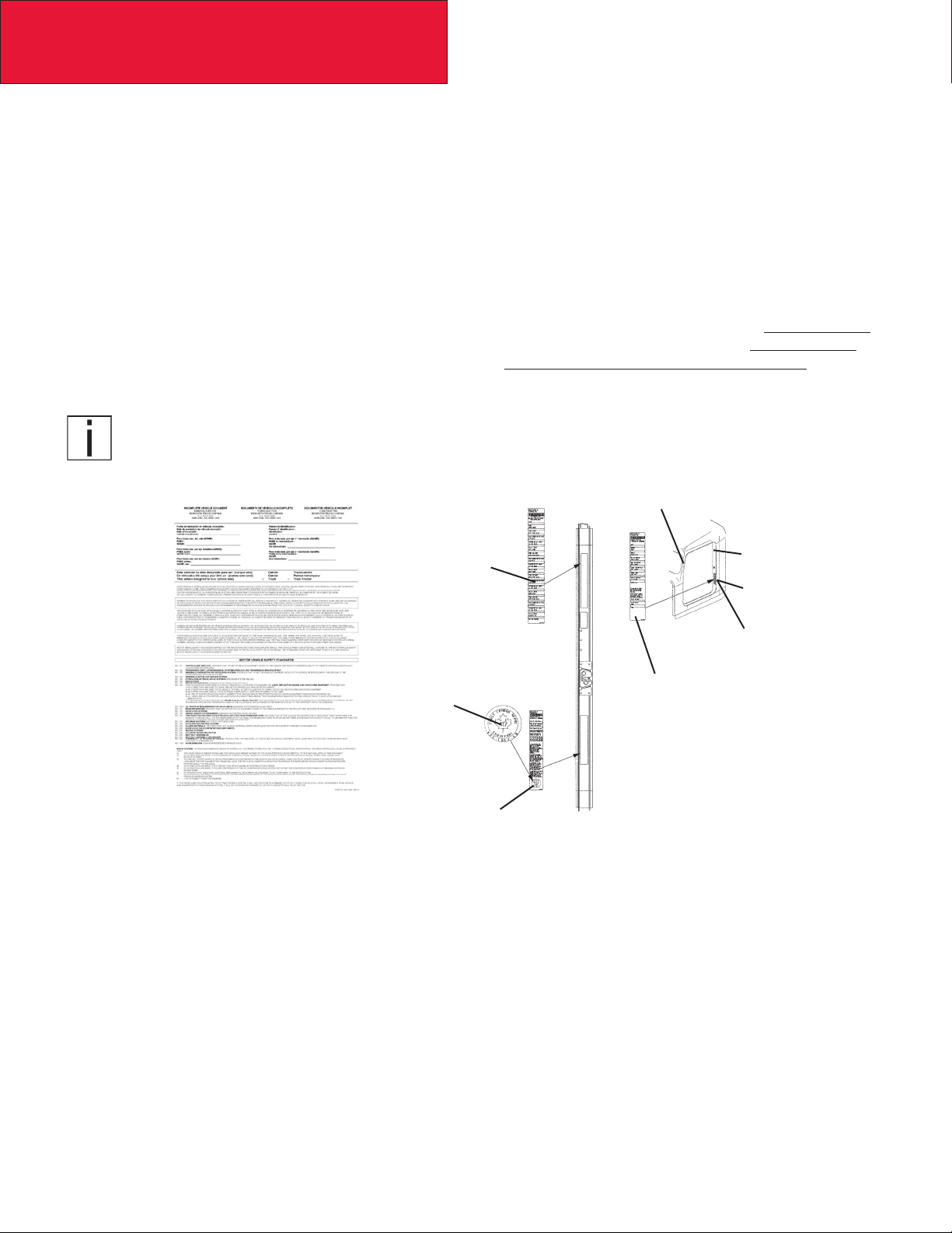
Incomplete Vehicle Certication
An Incomplete Vehicle Document is shipped with the vehicle, certifying that the vehicle is not complete. See Figure 2–1.
In addition, afxed to the driver’s side door frame or edge is an Incomplete Vehicle Certication label. See Figure 2–2. For
further information on Vehicle Certication and Identication, see APPENDIX A “VEHICLE IDENTIFICATION.”
NOTE
These documents list the U.S. or Canadian Federal Motor Vehicle Safety Standard regulations that the
vehicle complied with when it left the build plant. You should be aware that if you add, modify or alter any
of the components or systems covered by these regulations, it is your responsibility as the Intermediate or
Final Stage Manufacturer to ensure that the complete vehicle is in compliance with the particular regula-
tions upon completion of the modications.
U.S. EPA Noise Label (U.S. registered vehicles only)
Final Stage Manufacturer
Label to be Installed by
Final Stage Manufacturer
Chassis Serial
Number
Vehicle Emission Control
Information Label
FIGURE 2-1. Incomplete Ve-
hicle Certication Document
Tire, Rim and
Weight Rating
Data label
Safety Mark (Canadian
Registry Only)
Incomplete Vehicle
Certication Label
Major Components and
Weights Label
FIGURE 2-2. Locations of Certica-
tion Labels - Driver’s Door and Frame
As the Intermediate or Final Stage Manufacturer, you should retain the Incomplete Vehicle Document for your records. In
addition, you should record and retain the manufacturer and serial number of the tires on the vehicle. Upon completion
of the vehicle (installation of the body and any other modications), you should afx your certication label to the vehicle
as required by Federal law. This tag identies you as the “Intermediate or Final Stage Manufacturer” and certies that the
vehicle complies with Federal Motor Vehicle Safety Standards. (See Figure 2–2.) Be advised that regulations affecting the
intermediate and nal stage manufacturer may change without notice. Ensure you are referencing the most updated copy
of the regulation during the certication and documentation processes.
In part, if the nal stage manufacturer can complete and certify the vehicle within the instruction in the incomplete vehicle
document (IVD) the certication label would need a statement that reads, “This vehicle has been completed in accordance
with the prior manufacturers‚ IVD where applicable. This vehicle conforms to all applicable Federal Motor Vehicle Safety
Standards [and Bumper and Theft Prevention Standards if applicable] in effect in (month, year).”
However, if the vehicle can not be completed and certied with in the guidance provided in the IVD, the nal stage manufacturer must ensure the vehicle conforms to all applicable Federal Motor Vehicle Safety Standards (FMVSS). The nal
stage manufactures certication label would need a statement that reads, “This vehicle conforms to all applicable Federal
Motor Vehicle Safety Standards [and Bumper and Theft Prevention Standards if applicable] in effect in (month, year).”
02/15
2-2
Page 15

Section 2
Safety & Compliance
These statements are just part of the changes to the new certication regulation. Please refer to the Feb 15, 2005 nal
rule for all of the details related to this regulation. You can contact NTEA Technical Services Department at 1-800-441NTEA for a copy of the nal rule (DocID 101760).
For Canadian nal stage manufacturers see:
http://www.gazette.gc.ca/index-eng.html; and
http://www.tc.gc.ca/eng/acts-regulations/menu.htm for the regulations.
Or contact:
Transport Canada
Tower C, Place de Ville, 330 Sparks Street
Ottawa, Ontario K1A 0N5
(613) 990-2309
TTY: 1-888-675-6863
Noise and Emissions Requirements
NOTE
This truck may be equipped with specic emissions control components/systems* in order to
meet applicable Federal and California noise and exhaust emissions requirements. Tampering
with these emissions control components/systems* is against the rules that are established by the
U.S Code of Federal Regulations, Environment Canada Regulations and California Air Resources
Board (CARB). These emissions control components/systems* may only be replaced with original
equipment parts.
Additionally, most vehicles in North America will be equipped with a Greenhouse Gas (GHG)
“Vehicle Emission Control Information” door label indicating its certied conguration. The vehicle
components listed on this label (as shown in Figure 2-3) are considered emission control devices.
Modifying (i.e. altering, substituting, relocating) any of the emissions control components/sys-
tems dened above will affect the noise and emissions performance/certication. Modications
that alter the overall shape and aerodynamic performance of a tractor will also affect the emis-
sion certication. If modications are required, they must rst be approved by the manufacturer.
Unapproved modications could negatively affect emissions performance/certication. There is no
guarantee that proposed modications will be approved.
Tires may be substituted provided the new tires possess a Coefcient of rolling resistance (Crr)
equal to or lower than Crr of the original tires. Consult with your tire supplier(s) for appropriate
replacement tires.
Contact the engine manufacturer for any requirements and restrictions prior to any modications.
• For Cummins Contact 1-800-DIESELS or your local Cummins distributor. Reference AEB 21.102.
It is possible to relocate the DEF tank, however the relocation requirements need to be followed. Any variance from the
relocation requirements may cause the emissions control components/systems to operate improperly potentially resulting
in engine de-rate. See page 4-3 for relocation requirements.
NOTE
All 2013 engine emissions certied vehicles will be equipped with an On-Board Diagnostics
(OBD) system. The OBD system is designed to detect malfunctions of any engine or vehicle component that may increase exhaust emissions or interfere with the proper performance of the OBD
system itself.
2-3
02/15
Page 16

Section 2
Safety & Compliance
All diesel engines will be equipped with an On-Board Diagnostics (OBD) system. The OBD
system consists of computer program on one or more of the vehicle’s Electronic Control Units
(ECUs). This program uses information from the control system and from additional sensors to
detect malfunctions. When a malfunction is detected, information is stored in the ECU(s) for diagnostic purposes. A Malfunction Indicator Light (MIL) is illuminated in the dash to alert the driver of
the need for service of an emission-related component or system.
To ensure compliance to emissions regulations, the nal conguration of certain features of the completed vehicle
must meet specic requirements. This section describes requirements relevant for only the most common or critical modications done by body builders. For a complete description of acceptable modications, see the application
guidance available from the manufacturer of the engine installed in the chassis.
Fuel System
The following are highlights of some of the more common or critical aspects of this system.
The overall system restriction may not exceed the restriction limitations set forth by the engine manufacturer for both
supply and return.
• Ensure that fuel lines are not pinched or can potentially be damaged when installed between body and frame
• Fuel lines must be routed and secured without dips or sags
• There must be easy access to lter(s) and ll cap
• The tank vent may not obstructed
• Added accessories (heaters, generators) cannot introduce air into system
• Fuel tank must be located so that the full level is not above cylinder head
• “Ultra Low Sulfur Fuel Only” labels must be present on the dash and fuel ll
• Modication of the pressure side secondary lter and plumbing is not allowed without engine manufacturer
approval
• Body installation of fuel tank or routing of lines must not cause signicant increase in fuel temperature
• Fuel hoses shall meet or exceed OEM supplied hose material construction specications
Compressed Air System
The following are highlights of some of the more common or critical aspects of this system.
• Air system modication must meet applicable FMVSS regulations
• Compressed Air tank may not be modied (exception – addition or removal of ttings or relocation of the tank)
02/15
• Added devices or bodywork may not interfere with or rub air lines
• Air supply to the engine doser may not be restricted or disconnected
• Air lines should be routed, protected from heat, and properly secured to prevent damage from other
components
• Care should be taken so that air lines do not rub against other components
• Care should be taken to protect the air system from heat sources.
2-4
Page 17

Section 2
Safety & Compliance
Exhaust and Exhaust After-treatment System
The following are highlights of some of the more common or critical aspects of this system.
• The following after-treatment and exhaust system components may not be modied:
• DPF assembly
• SCR Catalyst assembly
• Exhaust pipes between the engine and after-treatment devices (DPF, SCR Catalyst) and between
after-treatment devices
• NOx Sensor
• The following modications may only be done within the guidelines of the “DEF System Relocation Guide.”
• Modications to Diesel Exhaust Fluid (DEF) throttle, suction, or pressure lines
• Modication or relocation of the DEF tank
• Modication of coolant lines to and from the DEF tank
• All DEF and coolant lines should be routed, protected, and properly secured to prevent damage during vehicle
operation or other components
• If relocation of the DCU or ACM is necessary, use existing frame brackets and mount inside of frame anges
where necessary. Do not extend the harnesses
• The DPF, the SCR catalyst, or their mounting may not be modied
• The NOx sensor may not been relocated or altered in any way
• Exhaust pipes used for tailpipes/stacks must be properly sized, and must prevent water from entering
• Ensure adequate clearance between the exhaust and body panels, hoses, and wire harnesses
• The body in the vicinity of the DPF must be able to withstand temperatures up to 400°C (750°F)
• Do not add thermal insulation to the external surface of the DPF
• The SCR water drain hole may not be blocked
• Allow adequate clearance (25mm (1 inch)) for servicing the DPF sensors, wiring, and clamped joints
• Drainage may not come in contact with the DPF, SCR catalyst, sensors or wiring
• Allow sufcient clearance for removing sensors from DPF. Thermistors require four inches. Other sensors
require one inch
• Wiring should be routed, protected from heat, and properly secured to prevent damage from
other components
• The exhaust system from an auxiliary power unit (APU) must not be connected to any part of the vehicle
after-treatment system or vehicle tail pipe.
Cooling System
The following are highlights of some of the more common or critical aspects of this system.
• Modications to the design or locations of ll or vent lines, heater or defroster core, and surge tank are not
recommended
• With the exception of post-thermostat installation, additional accessories plumbed into the engine cooling
system are not permitted, at the risk of voiding vehicle warranty
• Coolant level sensor tampering will void warranty
2-5
02/15
Page 18

Section 2
Safety & Compliance
• When installing auxiliary equipment in front of the vehicle, or additional heat exchangers, ensure that
adequate air ow is available to the vehicle cooling system. Refer to engine manufacturer application guidelines for further detail
• When installing FEPTO drivelines, the lower radiator anti-recirculation seal must be retained with FEPTO
driveline clearance modication only
• Changes made to cooling fan circuit and controls are not allowed, with the exception of AC minimum fan on
time parameter
• See owner’s manual for appropriate winter front usage
Electrical System
The following are highlights of some of the more common or critical aspects of this system.
• Electrical harnesses providing battery power and electronic control signals to engine and emissions control/
vehicle OBD components including datalinks may not be spliced. These emissions control/vehicle OBD
components include the following:
• throttle pedal
• vehicle speed sensor
• after-treatment wiring
• If the alternator or battery is substituted, it must meet the requirements of the engine manufacture’s guidelines. This includes alternator ground voltage drop and alternator ground cable effectiveness. See the engine
manufacture’s guidelines for recommended test procedure. Additionally the maximum voltage differential and
the peak-peak voltage differential between the engine ECM block ground stud and battery negative terminal
may not exceed 500 mV under any combination of loads or operating conditions.
• Only an OBD compliant battery disconnect switch may be installed on vehicles equipped EPA 2013 and be-
yond compliant diesel engines. An OBD compliant switch and harness, even in the off position, supply a small
amount of power to the engine controller and enable certain emissions critical functions (e.g. DEF line purge).
Any modications to the electrical system which interrupt this power supply will cause OBD fault codes and
illumination of the MIL. In addition, such a modication will render the engine non-compliant with certain emis-
sion regulations. As a general rule of thumb, you can remove and replace the battery a battery disconnect
switch on a truck equipped with a battery disconnect switch at the factory. However, if a battery disconnect
switch was not installed in the factory a signicant harness modication is required before a battery disconnect switch can be added. Installation of aftermarket transfer-cases must address the vehicle speed sensor
position. The standard position of the speed sensor is at the transmission tail shaft. When a transfer-case is
added it is best to relocate the sensor to the axle side output shaft of the transfer-case. This is typically accomplished by adding a tone wheel into the driveline yoke assembly.
• Wiring extensions for the after-treatment wiring are available for relocating the DEF tank from your dealer via
Paccar Parts. For relocation of DEF tank, refer to the after-treatment section of this manual.
• The emission system requires an accurate Outside Air Temperature (OAT) reading in order to properly run
its control algorithms. The OAT sensor is located in the driver’s side mirror assembly on Kenworth trucks and
is shown in the gures below. If the body builder needs to modify the mirror assembly in any way, it is important the OAT sensor stay positioned on the mirror assembly. Running the vehicle without the OAT sensor
connected will cause the MIL lamp to illuminate. If needed, a replacement sensor can be ordered from your
Kenworth dealer.
02/15
2-6
Page 19
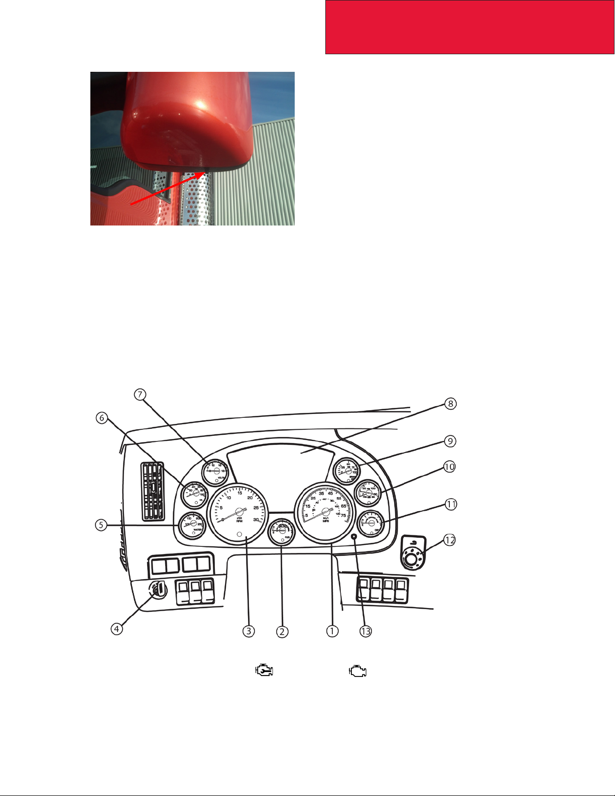
FIGURE 2-3: Aerodynamic Mirror OAT Sensor Location
• Coolant Sensor considerations are given in the Cooling section above
• The OBD/Diagnostic connector port is located below the dash to the left of the steering wheel. This connector
and its location may not be changed.
Section 2
Safety & Compliance
• All vehicles equipped with EPA 2013 compliant diesel and bi-fueled engines must be equipped with a Malfunction Indicator Lamp (MIL) lamp. This lamp is required to be an engine outline symbol as dened by ISO (International Standards Organization). The gure below shows the instrument cluster and MIL lamp position. Note
this lamp location is xed with respect to the controls and its location may not be changed if you are updating
the warning lamp cards.
FIGURE 2-4: Instrument Cluster for T680/T880 used with EPA 2013 Emission compliant
engines. The Check Engine lamp and/or the MIL will appear in the Driver Performance
Center (#8). See T680/T880 Operator’s Manual for more information.
• In addition to the sensors and lamps above, the emission system also depends on signals from the exhaust
DPF (Diesel Particulate Filter), SCR (Selective Catalytic Reduction), and NOx sensor. Wiring between these
devices, the Dosing Control Unit (DCU) and engine ECM should not be tampered with or altered in any way.
2-7
02/15
Page 20

Section 2
Safety & Compliance
Air Intake System
The following are highlights of some of the more common or critical aspects of this system.
• The air intake screen may not be blocked, either fully or partially
• Modication to the air intake system may not restrict airow. For example, pipe diameter may not be reduced
• All sensors must be retained in existing locations
• To retain system seal, proper clamp torque must be used. Refer to service manual for proper clamp torque
Charge Air Cooler System
The following are highlights of some of the more common or critical aspects of this system.
• The Charge Air Cooler may not be modied
• The installation of engine overspeed shutdown devices must not introduce restriction in the intake system
• All plumbing associated with the charge air cooler may not be modied
02/15
2-8
Page 21

Section 3
Dimensions
DIMENSIONS
This section has been designed to provide enough information to successfully layout chassis in the body planning
process. Optional equipment may not be depicted. Please contact your local Kenworth dealer if more dimensional
information is desired.
ABBREVIATIONS
Throughout this section, and in other sections as well, abbreviations are used to describe certain characteristics on your
vehicle. The chart below lists the abbreviated terms used.
TABLE 3-1. Abbreviations Used
CA BACK OF CAB TO CENTERLINE OF REAR AXLE OR CENTERLINE OF TANDEMS ON TANDEM SUSPENSION
EOF FRAME RAIL OVERHANG BEHIND REAR AXLE – MEASURED FROM THE CENTERLINE OF TANDEMS
FS FRONT SUSPENSION HEIGHT
RS REAR SUSPENSION HEIGHT
WB WHEELBASE
SOC SIDE OF CAB
BOC BACK OF CAB
TURNING RADIUS
Approximate turning radius specications are listed in the following tables as a general guide. It is important to note that
optional components may alter the results.
TABLE 3-2. Turning Radius
Model Steering Gear Front Axle Front Wheel Front Tire
T680/T880
Single Gear
HD94 or
THP60
Dana Spicer
E-1202I 12K or
E13221 13.2K
Accuride 50487
or Alcoa 88367
22.5 X 8.25
295/75R22.5
Rear
Suspension
Tandem
52” Axle
Spacing
Wheel Base
(in.)
181 26.7
193 26.9
201 28.0
213 29.7
220 30.6
232 32.3
240 33.4
252 35.0
260 36.1
272 37.7
280 38.8
291 40.4
303 42.0
323 44.7
331 45.8
Turning
Radius (ft)
3-1
TABLE 3-2 CONTINUES ON NEXT PAGE…
02/15
Page 22

Section 3
Dimensions
TABLE 3-2 CONTINUED
Model Steering Gear Front Axle Front Wheel Front Tire
T680/T880
T880
T880
Single Gear
HD94 or
THP60
Single Gear
SD110 or
TAS85
Dual Gears
HD94 or
THP60
Dana Spicer
E-12021 12K or
E-13221 13.2K
Dana Spicer
E-14621
Dana Spicer
D2000 20K
Standard Track
Accuride 50487
or Alcoa 88367
22.5 X 8.25
Alcoa 89365
22.5 X 9
Alcoa 89365
22.5 X 9
11R22.5
315/80R22.5
315/80R22.5
Rear
Suspension
Tandem
52” Axle
Spacing
Tandem
52” Axle
Spacing
Tandem
52” Axle
Spacing
Wheel Base
(in.)
181 26.9
193 27.4
201 28.5
213 30.2
220 31.2
232 32.9
240 34.0
252 35.7
260 36.8
272 38.4
280 39.6
291 41.1
303 42.8
323 45.6
331 46.7
181 26.9
193 26.9
201 27.9
213 29.6
220 30.5
232 32.2
240 33.2
252 34.0
260 35.1
272 36.7
280 37.8
291 39.2
303 40.8
323 43.4
331 44.5
181 28.1
193 28.6
201 29.7
213 31.5
220 32.5
232 34.2
240 35.3
252 35.2
260 36.3
272 38.0
280 39.1
291 40.6
303 42.2
323 45.0
331 46.0
Turning
Radius (ft)
02/15
TABLE 3-2 CONTINUES ON NEXT PAGE…
3-2
Page 23

TABLE 3-2 CONTINUED
Section 3
Dimensions
Model Steering Gear Front Axle Front Wheel Front Tire
T880
T880
Dual Gears
HD94 or
THP60
Dual Gears
HD94 or
THP60
Dana Spicer
D2000 20K
Standard Track
Dana Spicer
D2000 20K
Standard Track
Alcoa 82362
22.5 X 12.25
Alcoa 82362
22.5 X 12.25
385/65R22.5
425/65R22.5
Rear
Suspension
Tandem
52” Axle
Spacing
Tandem
52” Axle
Spacing
Wheel Base
(in.)
181 28.1
193 28.6
201 29.8
213 31.5
220 32.5
232 34.2
240 35.4
252 35.3
260 36.4
272 38.0
280 39.1
291 40.6
303 42.2
323 45.0
331 46.1
181 28.1
193 28.6
201 29.8
213 31.5
220 32.5
232 34.2
240 35.4
252 36.7
260 37.8
272 39.5
280 40.7
291 42.2
303 43.9
323 46.8
331 47.9
Turning
Radius (ft)
3-3
02/15
Page 24
Section 3
Dimensions
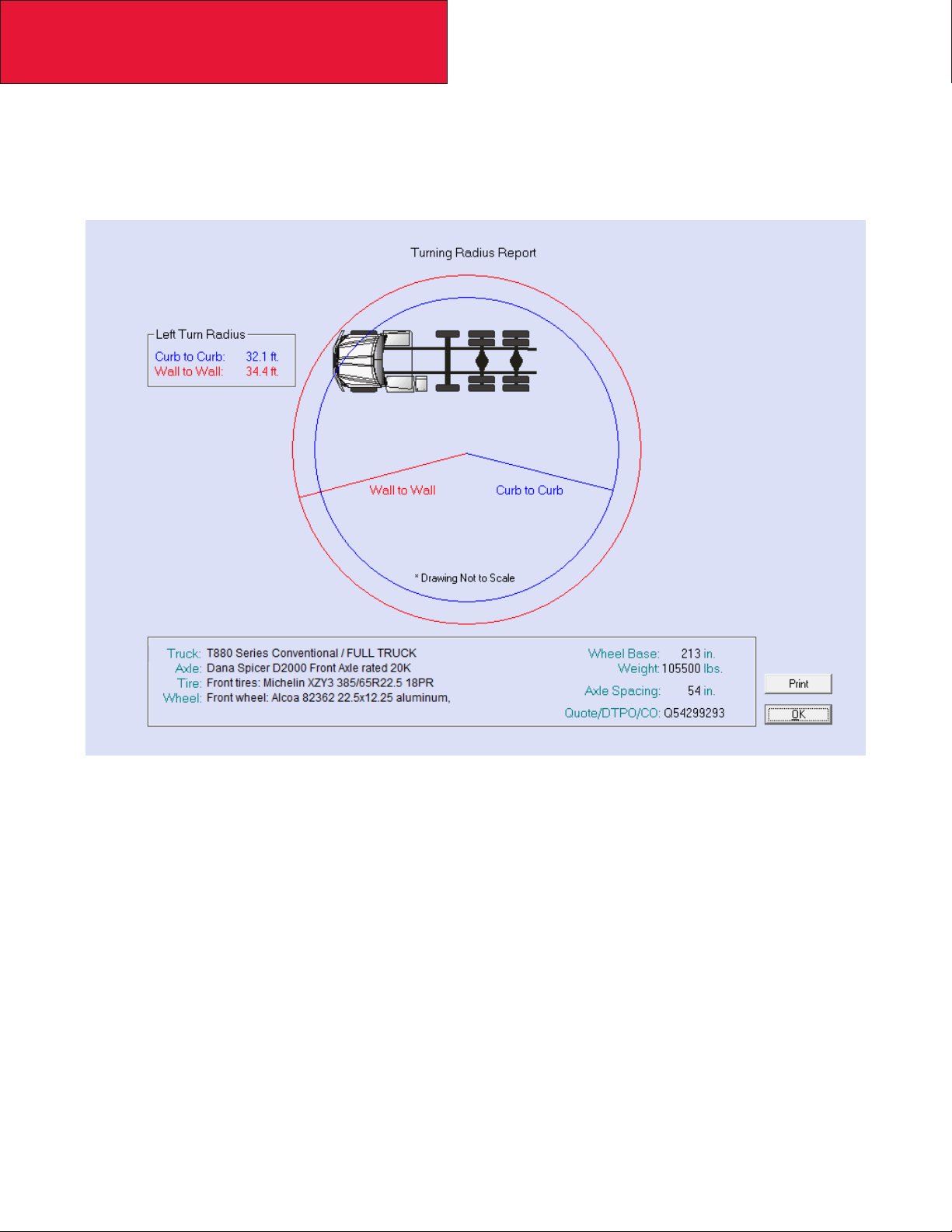
Prospector Turn Circle Analysis:
Please see Figure 3-2 as an example of Kenworth’s turn circle calculation made in Prospector for your specic chassis.
Your local Kenworth dealer can provide this information to you.
FIGURE 3-1. Prospecter Turn Circle Analysis
Please consult your local Kenworth Dealer for this information, as it is chassis specic.
02/15
3-4
Page 25

Section 3
Dimensions
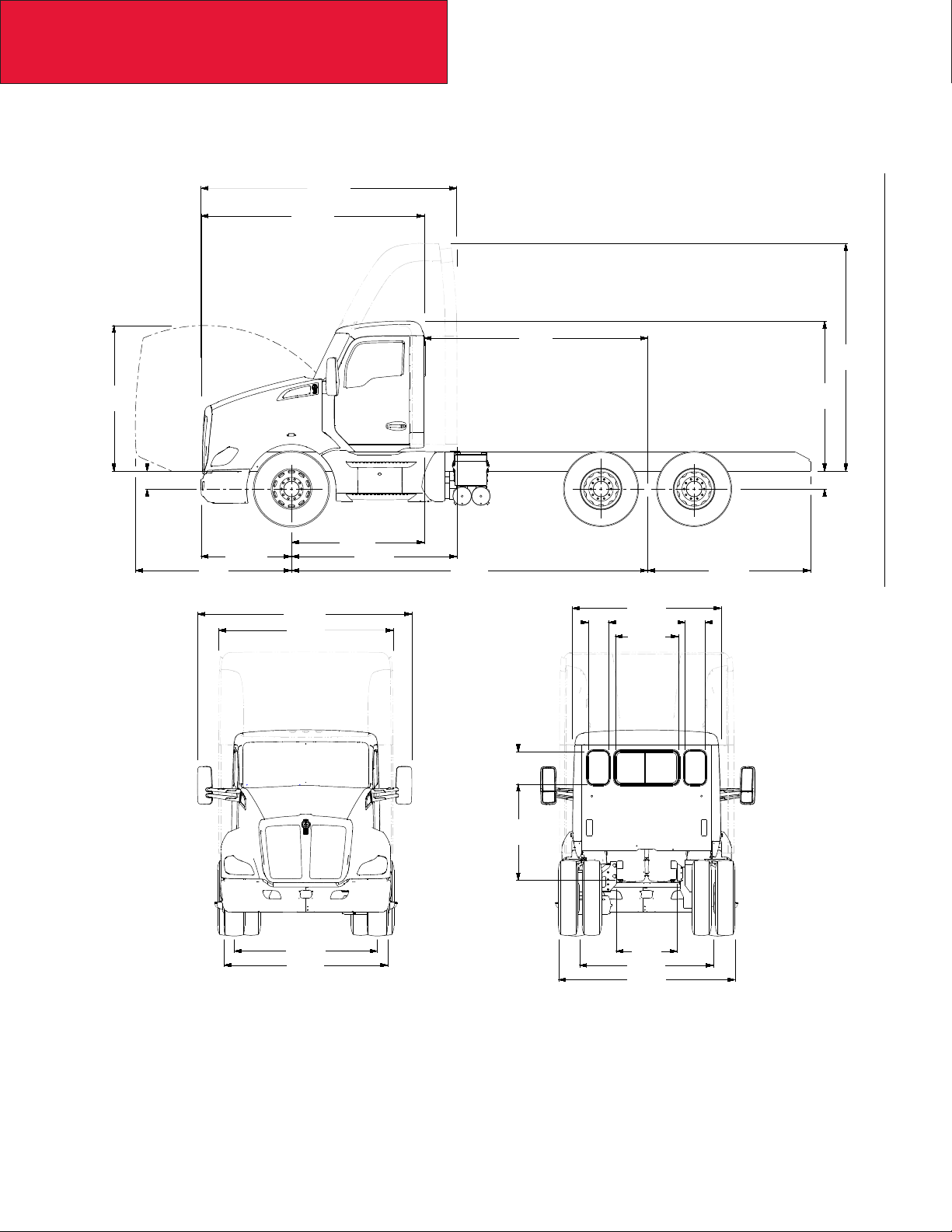
OVERALL DIMENSIONS
This section includes drawings and charts of the following Class 8 models: T680 and T880, including the 52” sleeper
On the pages that follow, detail drawings show particular views of each vehicle, all dimensions are in inches (in). They
illustrate important measurements critical to designing bodies of all types. See the “Contents” at the beginning of the
manual to locate the drawing that you need.
Note: To determine overall height please locate the chart Table 3-3 on page 3-12 and add that value to the height. All
heights are given from the bottom of the frame rail.
Kenworth also offers .dxf les and frame layouts of ordered chassis four weeks prior to build. Please speak with your
salesman to request this feature when specifying your chassis.
3-5
02/15
Page 26
Section 3
82.5
Dimensions
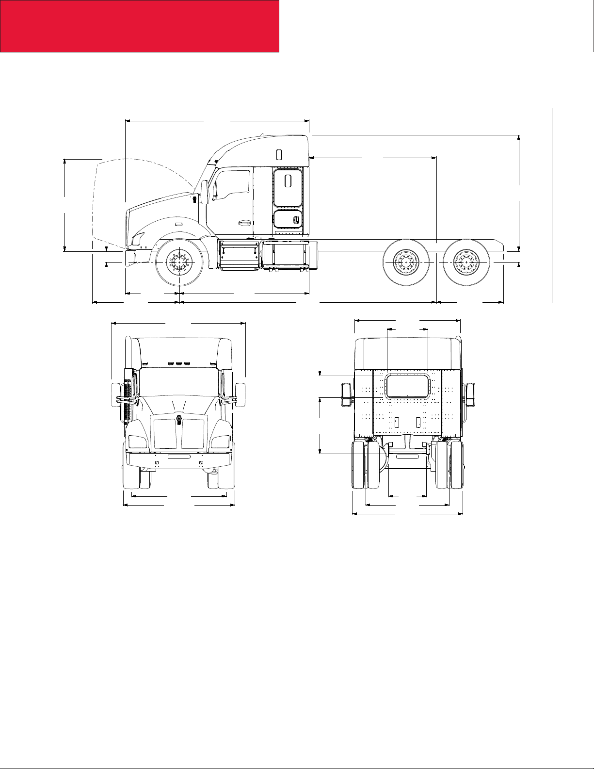
T680 STANDARD HOOD DAYCAB
The following drawings are of a standard T680 Standard Hood Daycab, shown with standard chassis components.
142.9
124.5
CA
127.1
85.6
FS
50.5 92.4
77
119.6
97.3
74.1
WB
18.3
53.6
11.3
83.8
RS
EOF
11.3
33.3
02/15
79.9
91.5
34
74.8
98.5
3-6
Page 27
Section 3
82.5
Dimensions
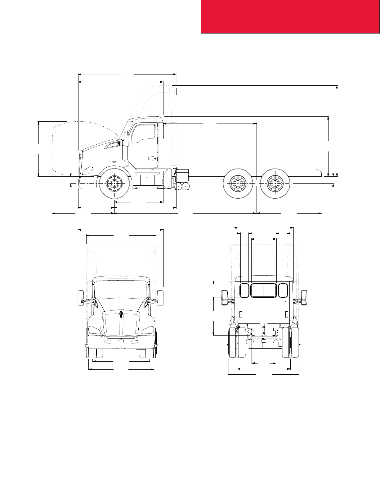
T680 MX (SHORT) HOOD DAYCAB
The following drawings are of a standard T680 MX (Short) Hood Daycab, shown with standard chassis components.
137
118.6
CA
127.1
76.8
FS
87.5
50.5
119.6
97.3
68.1
86.5
WB
18.3
53.6
11.3
83.8
RS
EOF
11.3
33.3
79.9
91.5
3-7
34
74.8
98.5
02/15
Page 28
Section 3
Dimensions
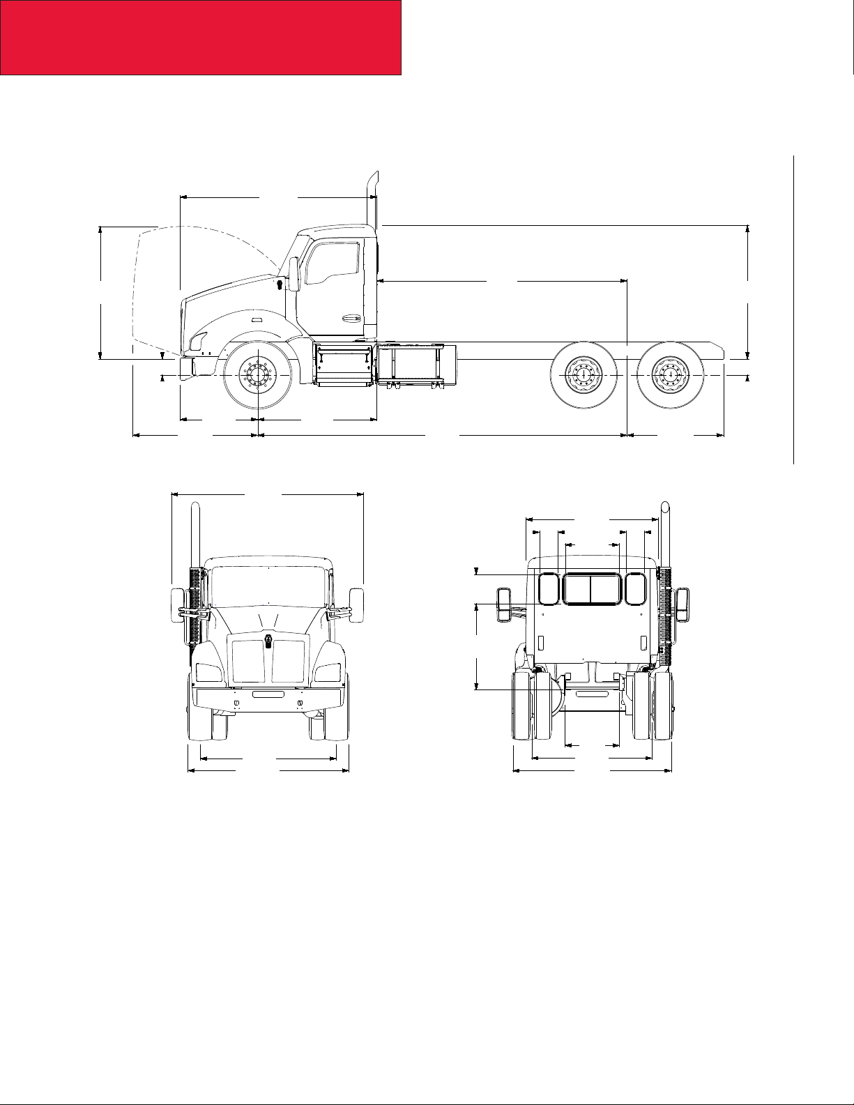
T880 STANDARD HOOD DAYCAB
The following drawings are of a standard T880 Standard Hood Daycab, shown with standard chassis components.
122.5
82.5
CA
FS
48.4 74.1
77.9 WB EOF
119.7
82.5
11.3
33.3
18.3
53.6
83.8
RS
11.3
02/15
84.7
100.2
34
74.8
98.5
3-8
Page 29
Section 3
Dimensions
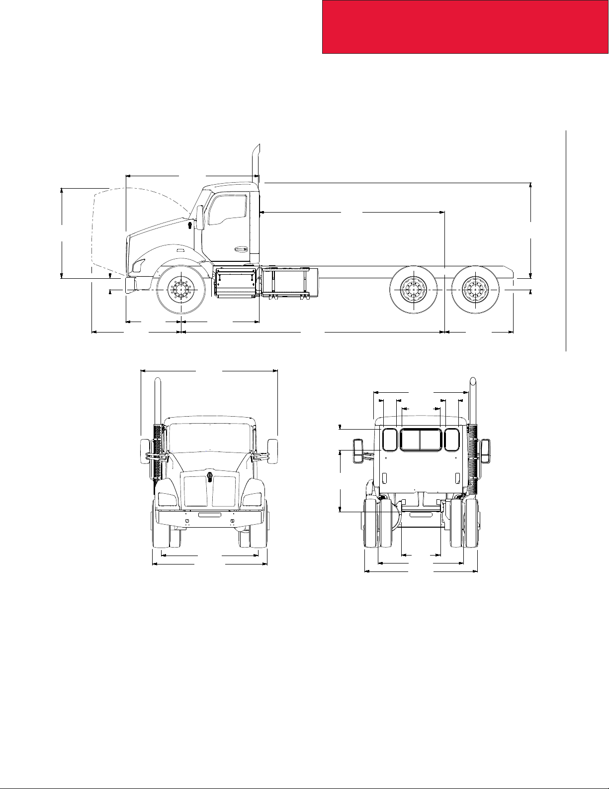
T880 MX (SHORT) HOOD DAYCAB
The following drawings are of a standard T880 MX (Short) Hood Daycab, shown with standard chassis components.
116.6
CA
78.6
FS
77.9
48.4
119.7
68.2
WB EOF
82.5
11.3
33.3
18.3
53.6
11.3
83.8
RS
84.7
100.2
3-9
34
74.8
98.5
02/15
Page 30
Section 3
Dimensions
T880 STANDARD HOOD WITH 52” SLEEPER
The following drawings are of a standard T880 Standard Hood with 52” Sleeper, shown with standard chassis components.
164.4
CA
104
82.5
FS
48.4
119.7
84.7
100.2
RS
116
94.7
36.4
19.5
50.3
34
74.8
98.5
02/15
3-10
Page 31

Section 3
Dimensions
T880 MX (SHORT) HOOD WITH 52” SLEEPER
The following drawings are of a standard T880 MX (Short) hood with 52” Sleeper, shown with standard chassis components.
158.5
CA
104
78.6
FS
48.4
119.7
84.7
100.2
RS
110.1
94.7
36.4
19.5
50.3
34
74.8
98.5
3-11
02/15
Page 32

Section 3
Dimensions
RIDE HEIGHTS
The front (FS) and rear (RS) suspension ride heights are provided as a basic tool to determine the overall height of the
cab, height of exhaust components, and frame heights. The heights are all calculated from the centerlines of the axles,
please be sure to include the tire radius dimension to determine overall height. Note: the frame rail height itself will not
affect the overall height as all components are located from the bottom of the frame rail.
82.5
TABLE 3-3. Ride Heights. To calculate the frame height use the following formulas:
Front Frame Height = FS + 1/2 Front Tire Diameter
Rear Frame Height = RS + 1/2 Rear Tire Diameter
Front Suspension (T680/T880)
Front Suspension (FS) Laden: Unladen:
12K Taperleaf 10.3” 11.5”
13.2K Taperleaf 10.3” 11.5”
14.6K Taperleaf 10.3” 11.7”
16K Taperleaf 10.6” 12.3”
20K Taperleaf 10.4” 11.9”
22K Multi-stage Taperleaf 10.7” 12.7”
RSFS
02/15
3-12
Page 33

Section 3
Dimensions
Rear Suspension (All Models). Common Rear Suspensions are shown here, for detailed
suspensions please use the Rear suspension layouts on pages 3-18 to 3-33.
Rear Suspension Laden: Unladen:
Kenworth AG400L 8.5” 8.5”
Kenworth AG400 9” 9”
Kenworth AG460 10.5” 10.5”
Kenworth AG690 Tridem 10.5” 10.5”
Reyco 79KB 23K Rating 8.3” 10.8”
Reyco 102 38K Rating 9.2” 10.8”
Chalmers 854-40-L-HS 40K Rating 9.6” 11”
Chalmers 854-46-H 46K Rating 10.1” 12.4”
Chalmers 854-50-H-HS 50K Rating 10.8” 12.5”
Chalmers 865-65-XL 65K Rating 13” 15.7”
Hend HMX400 16.5” Saddle 9.5” 10.6”
Hend HMX400 17.5” Saddle 10.5” 11.6”
Hend HMX460 46K 16.5” Saddle 9.5” 10.6”
Hend HMX460 46K 17.5” Saddle 10.5” 11.6”
Hendrickson Primaax EX 46K Rating 10” 10”
Hendrickson RT463 46K Rating 10” 11.1”
Hend RT523 52K 6” Saddle 9.9” 11”
Neway ADZ246 46K Rating 10” or 12” 10” or 12”
Neway ADZ252 52K Rating 10” or 12” 10” or 12”
Neway ADZ369 69K Tridem 10” or 12” 10” or 12”
Neway ADZ378 78K Tridem 10” 10”
3-13
02/15
Page 34

Section 3
Dimensions
REAR SUSPENSION LAYOUTS
The rear suspension layouts are provided as a tool to help layout bodies prior to arrival. The applicable dimensions are
shown. Be sure to check the axle spacing that is shown, as alternate spacings may exist and could change some of the
dimensions. The dimensions shown below are the most typical installations, in special cases some hole locations will
move. If you are planning on using the holes shown for your body installation, please conrm with your local KW dealer
that the drawing below will be the installation used on your specic truck. Ensure that proper torque is used to reinstall any
suspension components. See Tables 7-1 and 7-2 on page 7-7.
It would be a good idea in this case to order the frame layout of your chassis along with your truck order. This can be done
on any Kenworth truck, and will be provided 4 weeks ahead of the build schedule.
If there are hole locations that are not detailed please work with your local Kenworth Dealer to request that information.
Additionally optional axle spacings are shown in the charts, if you would like details on the frame drilling with optional
spacings, please contact your local Kenworth dealer.
NOTE: Actual axle spacing can depart from nominal due to axle slant requirements. Final axle spacing can vary by more
than an inch from nominal in some cases. If precise axle spacing is critical due to body installation or state/local regulatory
requirements please contact Kenworth Applications/technical Support for assistance.
02/15
3-14
Page 35

AG400L TANDEM
Section 3
Dimensions
59.4
58.3
53.8
AG400L Suspensions
56.9
54.7
8.5
Axle Spacing
TABLE 3-4. Rear Suspension Options
Suspension Type Rating Axle Spacing
AG400L Tandem 40K 52" 8.5" 8.5"
AG400L Tandem 40K 54" 8.5" 8.5"
NOTE: Actual axle spacing can depart from nominal due to axle slant requirements. Final axle spacing can vary by more
than an inch from nominal in some cases. If precise axle spacing is critical due to body installation or state/local regulatory
requirements please contact Kenworth Applications/technical Support for assistance.
Laden Ride
Height
Unladen Ride
Height
3-15
02/15
Page 36

Section 3
Dimensions
AG400 TANDEM
60.6
AG400 Suspensions
58.5
48.0
45.9
Ride
Height
Axle Spacing
TABLE 3-5. Rear Suspension Options
Suspension Type Rating Axle Spacing
AG400 Tandem 40K 52" 9" 9"
AG400 Tandem 40K 54" 9" 9"
NOTE: Actual axle spacing can depart from nominal due to axle slant requirements. Final axle spacing can vary by more
than an inch from nominal in some cases. If precise axle spacing is critical due to body installation or state/local regulatory
requirements please contact Kenworth Applications/technical Support for assistance.
Laden Ride
Height
Unladen Ride
Height
02/15
3-16
Page 37

AG460 TANDEM
Section 3
Dimensions
67.7
65.8
AG460 Suspensions
52.0
49.9
10.5
60.0
TABLE 3-6. Rear Suspension Options
Suspension Type Rating Axle Spacing
AG460 Tandem 60" Spacing 46K 60" 10" 10"
NOTE: Actual axle spacing can depart from nominal due to axle slant requirements. Final axle spacing can vary by more
than an inch from nominal in some cases. If precise axle spacing is critical due to body installation or state/local regulatory
requirements please contact Kenworth Applications/technical Support for assistance.
Laden Ride
Height
Unladen Ride
Height
3-17
02/15
Page 38

Section 3
Dimensions
AG690 TRIDEM
87.6
85.5
54.0
AG690 Tridem Suspension
TABLE 3-7. Rear Suspension Options
Suspension Type Rating Axle Spacing
76.0
73.9
54.0
Laden Ride
Height
10.5
Unladen Ride
Height
AG690 Tridem 69K 108" (54" + 54") 10" 10"
NOTE: Actual axle spacing can depart from nominal due to axle slant requirements. Final axle spacing can vary by more
than an inch from nominal in some cases. If precise axle spacing is critical due to body installation or state/local regulatory
requirements please contact Kenworth Applications/technical Support for assistance.
02/15
3-18
Page 39

REYCO 79KB SINGLE REAR AXLE
30.2 30.1
28.7 29.0
Section 3
Dimensions
Ride Height
Optional Reyco 79KB Suspensions
TABLE 3-8. Rear Suspension Options
Suspension Type Rating Axle Spacing
Reyco 79KB single 20K - 8.3” 10.8”
Reyco 79KB single 23K - 8.3” 10.8”
Reyco 79KB single 26K - 8.2” 11.3”
Reyco 79KB single 31K - 9.6” 12.2”
Laden Ride
Height
Unladen Ride
Height
3-19
02/15
Page 40

Section 3
Dimensions
REYCO 102 TANDEM REAR AXLE
Shown with a 52” Axle Spacing
Reyco 102 Suspension Data
TABLE 3-9. Rear Suspension Options
Suspension Type Rating Axle Spacing Laden Ride Height
Reyco 102 Tandem 38K 52” 9.2” 10.8”
NOTE: Actual axle spacing can depart from nominal due to axle slant requirements. Final axle spacing can vary by more
than an inch from nominal in some cases. If precise axle spacing is critical due to body installation or state/local regulatory
requirements please contact Kenworth Applications/technical Support for assistance.
Unladen Ride
Height
02/15
3-20
Page 41

NEWAY ADZ 123 SINGLE REAR AXLE
30.8
29.8
27.8
Section 3
Dimensions
18.0
16.0
2.1
8.0
2.7
4.6
Optional Neway ADZ Single Suspensions
TABLE 3-10. Rear Suspension Options
18.8
26.4
24.3
RIDE
HEIGHT
5.9
2.4
Suspension Type Rating Axle Spacing
Neway ADZ123 single 23K - 10” 10”
Neway ADZ126 single 26K - 10” 10”
Laden Ride
Height
Unladen Ride
Height
3-21
02/15
Page 42

Section 3
Dimensions
NEWAY ADZ 246 TANDEM SUSPENSION
Shown with a 54” Axle Spacing
57.7
56.7
54.7
44.9
42.9
52.1
50.7
2.7
4.6
8.0
AXLE SPACING
Optional Neway ADZ Tandem Suspensions
TABLE 3-11. Rear Suspension Options
Suspension Type Rating Axle Spacing
Neway ADZ246 tandem 46K 54” 10” 10”
Neway ADZ246 tandem 46K 60” 10” 10”
Laden Ride
Height
Unladen Ride
Height
RIDE
HEIGHT
Neway ADZ246 tandem 46K 72” 10” 10”
Neway ADZ252 tandem 52K 54” 10” 10”
Neway ADZ252 tandem 52K 60” 10” 10”
Neway ADZ252 tandem 52K 60” 12” 12”
NOTE: Actual axle spacing can depart from nominal due to axle slant requirements. Final axle spacing can vary by more
than an inch from nominal in some cases. If precise axle spacing is critical due to body installation or state/local regulatory
requirements please contact Kenworth Applications/technical Support for assistance.
02/15
3-22
Page 43

NEWAY ADZ 369 TRIDEM SUSPENSION
Shown with 54” Axle Spacings
84.7
83.7
81.7
71.9
69.9
Section 3
Dimensions
79.1
77.7
72.9
5.4
2.4
2.7
4.6
8.0
AXLE SPACING
AXLE SPACING
Optional Neway ADZ Tridem Suspensions
TABLE 3-12. Rear Suspension Options
Suspension Type Rating Axle Spacing
Laden Ride
Height
Neway ADZ369 tridem 69K 54” 10” 10”
Neway ADZ369 tridem 69K 60” 10” 10”
Unladen Ride
Height
RIDE
HEIGHT
Neway ADZ369 tridem 69K 60” 12” 12”
Neway ADZ378 tridem 78K 54” 10” 10”
Neway AD378 tridem 78K 60” 10” 10”
NOTE: Actual axle spacing can depart from nominal due to axle slant requirements. Final axle spacing can vary by more
than an inch from nominal in some cases. If precise axle spacing is critical due to body installation or state/local regulatory
requirements please contact Kenworth Applications/technical Support for assistance.
3-23
02/15
Page 44

Section 3
Dimensions
HENDRICKSON PRIMAAX EX TANDEM SUSPENSION
Shown with 54” Axle Spacings
Optional Hendrickson Primaax EX Tandem Suspensions
TABLE 3-13. Rear Suspension Options
Suspension Type Rating Axle Spacing
Hendrickson Primaax Tandem 46K 54” 10” 10”
Hendrickson Primaax Tandem 46K 60” 10” 10”
Hendrickson Primaax Tandem 46K 72” 10” 10”
NOTE: Actual axle spacing can depart from nominal due to axle slant requirements. Final axle spacing can vary by more
than an inch from nominal in some cases. If precise axle spacing is critical due to body installation or state/local regulatory
requirements please contact Kenworth Applications/technical Support for assistance.
Laden Ride
Height
Unladen Ride
Height
02/15
3-24
Page 45

Section 3
Dimensions
HENDRICKSON PRIMAAX EX TRIDEM SUSPENSION
Shown with 54” Axle Spacings
Optional Hendrickson Primaax EX Tridem Suspensions
TABLE 3-14. Rear Suspension Options
Suspension Type Rating Axle Spacing
Hendrickson Primaax Tridem 69K 54” 10” 10”
Hendrickson Primaax Tridem 69K 60” 10” 10”
NOTE: Actual axle spacing can depart from nominal due to axle slant requirements. Final axle spacing can vary by more
than an inch from nominal in some cases. If precise axle spacing is critical due to body installation or state/local regulatory
requirements please contact Kenworth Applications/technical Support for assistance.
Laden Ride
Height
Unladen Ride
Height
3-25
02/15
Page 46

Section 3
Dimensions
HENDRICKSON HMX TANDEM SUSPENSION
Shown with 54” Axle Spacing
Optional Hendrickson HMX Tandem Suspensions
TABLE 3-15. Rear Suspension Options
Suspension Type Rating Axle Spacing
Hendrickson HMX400 16.5” saddle 40K 54” 9.5” 10.6”
Hendrickson HMX400 17.5” saddle 40K 54” 10.5” 11.6”
Hendrickson HMX460 16.5” saddle 46K 54” 9.5” 10.6”
Hendrickson HMX460 17.5” saddle 46K 54” 10.5” 11.6”
NOTE: Actual axle spacing can depart from nominal due to axle slant requirements. Final axle spacing can vary by more
than an inch from nominal in some cases. If precise axle spacing is critical due to body installation or state/local regulatory
requirements please contact Kenworth Applications/technical Support for assistance.
Laden Ride
Height
Unladen Ride
Height
02/15
3-26
Page 47

HENDRICKSON RT TANDEM SUSPENSION
Shown with a 54” Axle Spacing Without Track Rods
Section 3
Dimensions
Optional Hendrickson RT Tandem Suspensions
TABLE 3-16. Rear Suspension Options
Suspension Type Rating Axle Spacing
Hendrickson RT463 6” saddle 46K 52” 10.0” 11.1”
Hendrickson RT463 6” saddle 46K 54” 10.0” 11.1”
Hendrickson RT463 7.19” saddle 46K 54” 11.2” 12.5”
Hendrickson RT463 7.94” saddle 46K 54” 11.9” 13.3”
Hendrickson RT463 6” saddle 46K 60” 10.0” 11.1”
Hendrickson RT463 7.94” saddle 46K 60” 11.9” 13.0”
Hendrickson RTE463 7.19” saddle 46K 52” 10.5” 11.6”
Hendrickson RT523 6” saddle 52K 52” 9.9” 11.0”
Hendrickson RT523 6” saddle 52K 54” 9.9” 11.0”
Hendrickson RT523 7.19” saddle 52K 54” 11.1” 12.2”
Hendrickson RT523 11” saddle 52K 54” 14.9” 16.0”
Hendrickson RT523 6” saddle 52K 60” 9.9” 11.0”
Laden Ride
Height
Unladen Ride
Height
Hendrickson RT523 7.19” saddle 52K 60” 11.1” 12.2”
NOTE: Actual axle spacing can depart from nominal due to axle slant requirements. Final axle spacing can vary by more
than an inch from nominal in some cases. If precise axle spacing is critical due to body installation or state/local regulatory
requirements please contact Kenworth Applications/technical Support for assistance.
3-27
02/15
Page 48

Section 3
Dimensions
CHALMERS 856-46 TANDEM SUSPENSION
Shown with a 54” Axle Spacing
Optional Chalmers Tandem Suspensions
TABLE 3-17. Rear Suspension Options
Suspension Type Rating Axle Spacing
Chalmers 854-40-L 40K 54” 8.9” 11.1”
Chalmers 854-40-L-HS 40K 54” 9.6” 11.1”
Chalmers 854-40-H 40K 54” 10.2” 12.4”
Chalmers 854-40-H-HS 40K 54” 10.9” 12.4”
Chalmers 854-46-L 46K 54” 8.9” 11.3”
Chalmers 854-46-L-HS 46K 54” 9.6” 11.3”
Chalmers 854-46-H 46K 54” 10.1” 12.5”
Chalmers 854-46-H-HS 46K 54” 10.9” 12.5”
Chalmers 854-50-L 50K 54” 8.9” 11.3”
Laden Ride
Height
Unladen Ride
Height
Chalmers 854-50-L-HS 50K 54” 9.6” 11.3”
Chalmers 854-50-H 50K 54” 10.1” 12.5”
TABLE 3-17 CONTINUES ON NEXT PAGE…
02/15
3-28
Page 49

TABLE 3-17 CONTINUED
Section 3
Dimensions
Suspension Type Rating Axle Spacing
Chalmers 854-50-H-HS 50K 54” 10.9” 12.5”
Chalmers 854-52-L-HS 52K 54” 9.6” 11.3”
Chalmers 854-52-H-HS 52K 54” 10.9” 12.5”
Chalmers 860-40-L 40K 60” 8.9” 11.1”
Chalmers 860-46-L 46K 60” 8.9” 11.3”
Chalmers 860-46-L-HS 46K 60” 9.6” 11.3”
Chalmers 860-46-H 46K 60” 10.1” 12.5”
Chalmers 860-46-H-HS 46K 60” 10.9” 12.5”
Chalmers 860-52-H 52K 60” 10.9” 12.5”
Chalmers 872-46-H-HS 46K 72” 11.0” 12.5”
NOTE: Actual axle spacing can depart from nominal due to axle slant requirements. Final axle spacing can vary by more
than an inch from nominal in some cases. If precise axle spacing is critical due to body installation or state/local regulatory
requirements please contact Kenworth Applications/technical Support for assistance.
Laden Ride
Height
Unladen Ride
Height
3-29
02/15
Page 50

Section 3
Dimensions
LIFT AXLES (PUSHERS AND TAGS)
The rear pusher axle layouts are provided as a tool to help layout bodies prior to arrival. The applicable dimensions are
shown. When using the pusher layouts to determine available frame space please be aware that clearances required are
not shown. For information that may not be detailed in these drawings work with your local Kenworth Dealer to request
that information.
Watson & Chalin 8K Steerable (SL0893SSR)
Watson & Chalin 10K Steerable (SL1093SSR)
/
02/15
3-30
Page 51

Section 3
Dimensions
Watson & Chalin Tru Track Alumilite 13.5K Steerable (SL1190SSR)
/
å
Watson & Chalin Tru Track 20K Steerable (SL2065)
/
3-31
02/15
Page 52

Section 3
Dimensions
Watson & Chalin 23K Steerable (SL2200) *Use with Duals Only*
Watson & Chalin Atlas 23K Non-Steerable (AL2200)
02/15
3-32
Page 53

Section 3
Dimensions
AXLE TRACK AND TIRE WIDTH
The dimensions provided in this section are representative of some typical product combinations. The purpose this section is to demonstrate some of the typical dimensions.
• Axle Track: The distance between the dual tire centerlines on a dual tire arrangement or the distance between
the tire centerlines on a single tire arrangement.
• Width: The distance over the outermost tire sidewall to sidewall.
These dimensions may be signicant to the following:
• Appearance relative to other tires and chassis mounted equipment.
• Load carrying capacity. Different wheel disc offset can have a positive or negative impact on the axle carrying capacity of the axle.
TABLE 3-18. Axle Width Calculation.
Axle - Drive Wheel Tire Conguration
Dana Spicer D46-170(H)(P)
46K Dual
Dana Spicer D46-170(H)(P)
46K Dual
Dana Spicer D46-170W(H)(P)
46K Dual Wide Track
Dana Spicer D46-170W(H)(P)
46K Dual Wide Track
Dana Spicer D46-170(H)(P)
46K Dual
Dana Spicer D46-170W(H)(P)
46K Dual Wide Track
Alcoa 88367
22.5X8.25
Alcoa 98363
24.5X8.25
Alcoa 88367
22.5X8.25
Alcoa 98363
24.5X8.25
Alcoa 82262
22.5X12.25
Alcoa 82262
22.5X12.25
Track
Dim “A”
11R22.5 4-4 73.3" 97.8"
11R24.5 4-4 73.6" 98.0"
11R22.5 4-4 79.2" 103.7"
11R24.5 4-4 79.5" 103.9"
425/65R22.5 2-4 72.7 88.9"
425/65R22.5 2-4 78.7" 94.9"
Overall Width
Dim “B:
3-33
TABLE 3-18 CONTINUES ON NEXT PAGE…
02/15
Page 54

Section 3
Dimensions
TABLE 3-18 CONTINUED
Axle - Steer Wheel Tire
Dana Spicer E-1322I 13.2K Alcoa 98363
24.5X8.25
Dana Spicer E-1322W 13.2K Alcoa 98363
24.5X8.25
Dana Spicer D2000 20K Alcoa 82462
24.5X12.25
Dana Spicer D2000 20K Alcoa 82462
24.5X12.25
Lift Axle Model Wheel Tire
W&C SL0893SSR
8K Steerable
W&C SL1093SSR
Steerable 10K
W&C SL1190SSR
Steerable 13.5K
W&C SL2065
Steerable 20K
W&C SL2200
Steerable 23K
W&C AL2200-STD Track
Non-Steerable 23K
W&C AL2200-STD Track
Non-Steerable 23K
W&C AL2200-Wide Track
Non-Steerable 23K
W&C AL2200-Wide Track
Non-Steerable 23K
Alcoa 66480
17.5x6
Alcoa 77349
19.5x7.5
Alcoa 88367
22.5x8.25
Alcoa 82362
22.5x12.25
Alcoa 88367
22.5x8.25
Alcoa 88367
22.5x8.25
Alcoa 82362
22.5x12.25
Alcoa 89465
22.5x9
Alcoa 84362
22.5x14
Brake Drum
Type
11R24.5 CAST 80.2" 91.0"
11R24.5 CAST 82.2" 93.0"
425/65R22.5 CAST 86.5" 102.7"
425/65R22.5 CAST 82.6" 98.8"
Wheel
Orientation
215/75R17.5 Same as FR 77.3" 85.8"
265/70R19.5 Same as FR 78.5" 88.5"
255/70R22.5 Same as FR 80.4" 90.7"
425/65R22.5 Same as FR 83.6" 99.8"
295/75R22.5
11R22.5
425/65R22.5
315/80R22.5
445/50R22.5
Same as RR,
dual
Same as RR,
dual
Same as RR,
single
Same as FR,
single
Same as RR,
single
Track
Dim “A”
Track
Dim “A”
78.2" 102.8"
72.2" 96.6"
78.4" 94.7"
64.7" 77.3"
80.6" 97.7"
Overall Width
Dim “B:
Overall Width
Dim “B”
02/15
3-34
Page 55

Section 3
Dimensions
GROUND CLEARANCE
This information is provided as a reference, not all optional equipment is included. In order to calculate the height on your
specic chassis, please use the ride height information provided on page 3-14. For comparison the FS value shown is
11.4” unladen and 10.4” laden.
TABLE 3-19. Ground Clearance for Fuel Tanks
Front
Suspension
20K
Taperleaf
Spring
Front Tires
425/65R22.5
Rear
Suspension
Hendrickson
HMX 460
17.5”
Saddle
Height
Rear
Tires
11R24.5
Fuel
Tank
Size
22”
Diameter
24.5”
Diameter
28.5”
Diameter
Dimension “B”
Dimension “A”
Component
Fuel Tank 16.3 17.2 14.9
DEF Tank 15.3 18.2 15.9
Fuel Tank 18.2 15.3 13
DEF Tank 15.8 17.7 15.4
Fuel Tank 21.4 12 9.7
DEF Tank 17.2 16.2 13.9
Distance from
Bottom of
Frame Rail (in)
Ground Clearance
(in)
Unladen Laden
3-35
02/15
Page 56

Section 3
Dimensions
TABLE 3-20. Ground Clearance for Battery Boxes
Dimension
“A”
Front
Suspension
20K Taperleaf Spring
1
Dimensions shown are for daycabs with high route exhaust. Sleeper ground clearance is reduced by 1.3 inches.
Front Tires
425/65R22.5
Tires
Rear
Suspension
Hendrickson
HMX 460
17.5” Saddle
Height
Rear Tires Component
Battery Box
with Air Tanks
Vocational
11R24.5
Battery Box
with Air Tanks
DPF1 Box 15.6 17.8 15.5
Distance
from
Bottom of
Frame Rail
(in)
17.3 16.2 13.9
17.8 15.7 13.4
Dimension “B” Ground
Clearance (in)
Unladen Laden
02/15
3-36
Page 57

Section 3
Dimensions
PTO CLEARANCES
The following visuals are provided to help aid in determining PTO locations and clearances. For specic dimensions
please work through your local Kenworth dealer. Note: Installations depict multiple PTOs.
In order to ensure the PTO area remains clear of air equipment, electrical and emissions equipment, Kenworth recommends always ordering PTO controls, even when installing the PTO aftermarket. Kenworth does offer a variety of factory
installed PTOs. Contact your local dealer for assistance.
Manual Transmission:
3-37
02/15
Page 58

Section 3
Dimensions
Allison Transmission:
02/15
3-38
Page 59

Section 3
Dimensions
T680/880 TRANSMISSION PTO APPLICATION GUIDE
This application guide indicates if a PTO has sufcient clearance to truck components in various mounting congurations.
A green “ok” indicates that there is sufcient clearance to other truck components. A red “x” indicates that there minimal
or no clearance and the application is not recommended. The truck components investigated in this guide include frame
rails, Set Back Front Axle (SBFA) rear shackle, SBFA Front Air Suspension (FAS) rear shackle, over-bell frame brace,
coolant return manifold, transmission clutch actuator, and exhaust system components.
Usage Notes:
1. This application guide is only applicable to T680/880 trucks.
2. Only the specied PTO congurations have been analyzed. Please submit an OAR to review other models
and/or congurations.
3. Horizontal crossover exhaust limits access behind PTO’s for shaft drives and other PTO attachments.
4. Fuel tank cross bracing may interfere with PTO’s and/or PTO attachments (such as hydraulic pumps). If this is
an issue, the cross brace may be moved to an alternate fuel tank support. “
5. Eaton FR transmissions require the use of a 30° adapter when installing Chelsea or Muncie transmission
PTO’s in the right hand position.
6. Eaton RT & Ultrashift Plus transmissions require the use of a 49° adapter when installing Chelsea transmission PTO’s in the right hand position.
7. Eaton RT & Ultrashift Plus transmissions require the use of a 55° adapter when installing Muncie transmission
PTO’s in the right hand position.
8. Eaton transmissions require the use of a 6 to 8 Bolt adapter when installing a 6 bolt PTO in the bottom position.
PTO Controls:
The T680/880 models have been designed to use electric in-dash switches to control air solenoids (Electric Over Air system, or EOA) which engage/disengage transmission PTOs. This system allows for increased control and interlock opportunities. This also keeps air lines for transmission PTO controls from routing inside the cab. In cab air valve actuators for
transmission PTO control are still available and are located on the cab oor on the LH side of the driver’s seat. Air valve
style transmission PTO actuators should not be installed on the dash due to the difculty of air-line routing. Customer in-
stalled transmission PTO controls for use with customer installed transmission PTO’s include a chassis and dash harness
pre-wire to ease the installation of in-dash transmission PTO controls at the body builder. It is strongly recommended that
the truck be coded for this if transmission PTO(s) could be installed after initial in-service date.
The EOA system is used to control PTO engagement. There are three different types of PTOs supported in the EOA software:
Single-Acting PTOs – these types of PTOs have a single air control. A single chassis node output controls the air solenoid, tand the air pressure engages the PTO – the lack of air pressure at the control port disengages the PTO.
Double-Acting PTOs – these types of PTOs have a dual air control. One air signal controls the engagement and one air
signal controls the disengagement. This can be achieved in one of two ways:
• A single-acting PTO is congured – the engage air control port is connected to the chassis node output and a
pilot inversion valve in the chassis air plumbing is connected to the second disengage air control port.
• Two chassis node outputs control the PTO. One chassis node output and solenoid is connected to the engage air
control port of the PTO, and one chassis node output and solenoid is connected to the disengage air control port.
Reversible PTOs – have three different operational states. Inactive – not engaged to driveline (no air control ports active).
Main direction –engaged to driveline (main air control port pressureized). Opposite direction –engaged to driveline (opposite air control port pressurized). If the vehicle is specied with a pTO installation from the factory, a protected PTO on/off
switch will be used. It will connect to the instrument panel harness ith a switch connector labeled “EOA x” x eing a number
between 1 and 10.
3-39
02/15
Page 60

Section 3
Dimensions
PTO Functionality Description
Power Take-Off (PTO)
The PTO category covers both ‘Single-Acting’ and ‘Double-Acting’ PTOs. Single-acting PTOs require air pressure on the
input cylinder to activate the function and will deactivate via an internal spring when air pressure is removed; air-on/springoff. Dual-acting PTOs require air pressure an input cylinder to activate and air pressure on a different input cylinder to
deactivate; air-on/air-off. This information is provided for additional clarication since the system appears identical from an
electronics-control aspect.
The PTO type depends on the actual brand and part number. Most examples in this document show double-acting. Whenever any PTO is engaged, a feedback signal will activate a single cluster telltale.
FIGURE 3-2. Single Acting and Dual Acting PTOs
TABLE 3-21. Current single-acting PTOs include:
Model Supplier Mounting Hyd. Clutch Actuator Actuator Type
238/489/680 Chelsea
CS/SH/TG8 Muncie
885 Chelsea Optional Single
230/236/442/660 Chelsea
CS/SH/TG6 Muncie
02/15
Bottom
RH Standard Single
3-40
Standard Single
Page 61

Section 3
Dimensions
TABLE 3-22. Current double-acting PTOs include:
Model Supplier Mounting Hyd. Clutch Actuator Actuator Type
823 Chelsea
828 Muncie
340 (reversible)
880 Optional Double
340 (reversible)
541 Back Any
Chelsea
Chelsea
Bottom
RH Standard
Eaton Transmission-Mounted PTO
When a PTO is ordered on an Eaton brand transmission it is controlled with EoA System. The PTO can be a single-acting
or double-acting and have one or two PTOs attached to the transmission. Optional park brake interlocks are available via
sales codes.
All PTOs have an engaged feedback signal that is routed to the cluster to illuminate a PTO. When any PTO is actively
engaged the cluster telltale will illuminate.
Standard Double
Double
Figure 3-3 shows the system diagram for a single-acting Eaton mounted transmission PTO. Signal ow is as follows:
• The dash switch labelled “PTO Switch #1” is activated by the user.
• The signal is received by the CECU and the optional interlocks are checked and veried.
• The Chassis Node receives a multiplexed CAN message to activate and send a power signal to the appropriately assigned solenoid.
• The solenoid activates and allows supplied air pressure to ow to the piped PTO port.
• The PTO activates and the ball switch closes sending a hardwired signal.
• The CECU and Engine ECM received this signal.
• The CECU sends a CAN message to the Cluster to activate the PTO telltale and the Engine changes state to
“PTO Mode”
FIGURE 3-3. Single-Acting Eaton PTO
3-41
02/15
Page 62

Section 3
Dimensions
The signal ow is the same for double-acting PTOs. The difference is that an inversion dump valve provides air pressure to
the “off” port when the EoA solenoid is not being command on.
FIGURE 3-4. Double-Acting Eaton PTO
Allison Transmission-Mounted PTO (a.k.a. Electric-Over-Hydraulic)
When a transmission PTO is ordered on an Allison brand transmission, it is always Electric-over-Hydraulic (EoH). From
the controls aspect, it looks like an “electric-only” type switch. The switch and telltales do not distinguish the difference
between EoH and EoA.
FIGURE 3-5. Allison Transmission-Mounted PTOs
02/15
3-42
Page 63

Section 3
Dimensions
Transmission PTO with Auto Suspension Dump/Inate
This feature requires Air Suspension Dump functionality. Upon PTO activation, if not already dumped, the NAMUX system
will command the air suspension to deate (“dump”) before the PTO is engaged. When the PTO switch is deactivated the
air suspension will re-inate. This feature is an optional sales code, but coded standard on some applications; such as
those with boom cranes.
With Allison transmission mounted PTOs the CECU EoA system does not directly know when the PTO is active since the
switch is wired directly to the TCM. In this case, the ECM is broadcasting a CAN messages indicating that the engine is in
PTO Mode. This is used as a proxy for the CECU to know when the PTO is active.
For Eaton mounted PTOs all functionality occurs within the CECU. When either the PTO switch is activated or the CECU
receives a message that the ECM is in PTO Mode CECU will begin the Auto Suspension Dump functionality. First, the
CECU checks applicable interlocks. If appropriate, it will send a CAN message to the Chassis Node requesting PTO solenoid activation and Suspension Dump activation.
3-43
02/15
Page 64

Section 3
Dimensions
FIGURE 3-6. Auto Susp Dump w/ Allison mtd PTO
02/15
3-44
Page 65

Section 3
Dimensions
Reversible PTO (a.k.a. Fwd/Rev PTO, a.k.a. 2-Position PTO)
Some transmission-mounted PTOs have two directions of spin. The Reversible PTO switch provides two CECU inputs for
forward & reverse and there are two non-latching solenoids pressurizing two single-acting cylinders on the PTO, see the
gure below.
FIGURE 3-7. EoA Reversible PTO Example
PTO States
Forward Reverse OFF
Fwd X
Ports
Rev X
TABLE 3-23. Reversible PTO States to Ports
Non-EoA Air Actuated PTOs
NGP models do not offer air controls mounted on the dash. In cases where the customer must have air controls, they are
mounted on the oor or side of seat. The block diagram is shown in Figure 3-8.
FIGURE 3-8. Air Actuated PTO (No Interlock)
3-45
02/15
Page 66

Section 3
Dimensions
PTO (Split-Shaft, Transfer Case, etc.)
Split-shaft PTOs are gearboxes between the transmission and rear axles. Much like transmission mounted PTOs, they
take driveline power from the transmission and divert it (“take it off”) to equipment such as pumps, winches, etc. Where
they differ is split-shaft PTOs are not mounted to the transmission and can handle signicantly more power and torque
than a traditional transmission-mounted PTO.
These gearboxes have a few different congurations; some split-shaft PTOs have a single pneumatic cylinder that simultaneously declutches the rear axle when activating the PTO,
Figure 3-10. This is known as “Pump Mode”. Other split-shaft PTOs have independently controls for PTO engagement and
rear axle declutch. This allows the drive while the PTO is running. Others have an additional PTO output pad that is separate from the main PTO output gear.
Transmission mounted PTOs, split-shaft PTOs, and non-EoA controlled PTOs are not exclusive to the type and can be
combined in nearly any conguration.
When the Rear Axle Declutch function is active a positive feedback signal activates a telltale in the cluster editable area.
The PTO active telltale is the same a transmission mounted PTO, see Figure 3-9..
FIGURE 3-9. Rear Axle Declutch Telltale
Figure 3-10 shows an example conguration where the customer has ordered a SS PTO with separate switches for Rear
Axle Declutch.
FIGURE 3-10. Split Shaft PTO Example #1
02/15
3-46
Page 67

Section 3
Dimensions
Split-Shaft PTO - Pump Mode
When the PTO controls are specied/congured to have a single switch controlling both the PTO Engage and Rear Axle
Declutch it is called “Pump Mode.” The controls and air piping architecture pressurizes the ports such that the PTO is
engaged and rear axle declutched at the same time. This is a common term used in the industry. When engaged, two
separate telltales will illuminate (from actual wired feedback) indicating the state of both PTO and Rear Axle Declutch.
Park Brake must be engaged to activate Pump Mode, if not, a popup message on the cluster will appear telling the driver
to do so.
Note that the functions themselves are not unique. Controlling both functions with a single switch is convenient and offers
additional interlocks. Positive feedback signals activate a PTO and Rear Axle Declutch telltales within the cluster editable
telltale area.
In the example below, a Pump Mode conguration is shown with dual-acting PTO ports. Notice that this is similar to Figure
3-10 except the Rear Axle Declutch cylinder is plumbed to activate/deactivate at the same time with the PTO engage
switch.
FIGURE 3-11. Pump Mode Example
Electric Over Air System Interlocking
By utilizing the Cab ECU to control the EOA system, the EOA switching has capabilities to be interlocked with other functions such as park brake application, vehicle speed, neutral gear selected, or a combination of these functions. Switch
activation will only occur if the interlock criteria are met. If the Cab ECU detects the switch is in the on position and if
applicable, the park brake interlock is validated by the Cab ECU, the Cab ECU will send a signal to the chassis node via
F-CAN. The EOA valve will be the same number as on the dash switch. Electronic Service Application (ESA) can be used
to add or remove the PTO engage park brake interlock. Depending on the application and the PTO type, the switches and
wiring may differ.
For single-acting PTOs, the chassis node will energize the coil on the EOA valve allowing air to engage the PTO.
For dual-acting PTOs, the PTO’s pilot valve will provide the air function to switch the air between engage and disengage.
For reversible PTOs, a protected PTO forward and a protected PTO reverse switch will be present in the dash. Each switch
controls a separate EOA solenoid, each solenoid is dedicated to either forward or reverse. If the Cab ECU detects both the
forward and reverse switches in the on position the Cab ECU will ignore the switch input for the second switch thrown and
provide a message in the cluster display informing the operator of the non-valid switch conguration
3-47
02/15
Page 68

Section 3
Dimensions
FIGURE 3-12. Sample Chassis Node and EOA Manifold. (congured to match Figure 3-13)
02/15
3-48
Page 69

Section 3
Dimensions
FIGURE 3-13. Wiring Diagram for Chassis Node, Cab Switches, and EOA Manifold. (congured to match
Figure 3-12)
3-49
02/15
Page 70

Section 3
Dimensions
10-Bolt PTO’s for Allison Transmissions
TABLE 3-24.
4000 Series
Brand PTO Truck Model 1 o’clock 8 o’clock 1 o’clock 8 o’clock 4 o’clock 8 o’clock
267-M3XK All x x ok x x x
267-M5XK All ok ok ok x ok ok
T680/880 ok ok ok x ok ok
T680SH/880SH ok x ok x ok ok
T680/880 ok x ok x ok ok
T680SH/880SH ok x ok x x ok
T680/880 ok x ok x ok ok
T680SH/880SH ok x ok x x ok
T680/880 ok ok ok x ok ok
T680SH/880SH ok ok ok x x ok
T680/880 ok x x x ok x
T680SH/880SH ok x x x ok ok
Chelsea
Muncie
277-B5XS
859-B5XS All ok x x x x x
870X-B3RS All ok x ok x x x
870X-B5RS All ok x ok x x x
890-B5XS All ok x ok x x ok
CD05-M3CX All ok ok ok ok ok ok
CD10-M1CX, DX
CD10-M3CX, DX
CS10-P1CX, EX All x x x x x x
CS10-P3CX, EX All x x x x x x
CS24-P1BX, KX All ok x ok x x x
CS24-P3BX, KX
CS41-P1CX, EX All ok x x x x x
CS41-P3CX, EX All ok x x x x x
HS24-P1BX, KX
HS24-P3BX, KX All ok ok ok x x ok
3000 Series -
1 & 8 Housing
3000 Series -
4 & 8 Housing
02/15
3-50
Page 71

Section 3
Dimensions
6 & 8 Bolt PTO’s for Eaton Transmissions
TABLE 3-25.
FR RT Ultrashift Plus
Brand Style PTO Bottom Right Bottom Right Bottom Right
230-V3XD/XK ok ok1,2,3 ok ok1,2,3 ok ok1,2,3
Chelsea
6-Bolt
8-Bolt
236-V3XD/XK
270-B3XD/XK ok ok1,2,3 ok ok1,2,3 ok ok1,2,3
340-V5XD ok ok1,2,3 ok ok1,2,3 ok ok1,2,3
442-V3XK
660-V3XK
238-V3XD/XK ok n/a ok n/a ok n/a
489-V3XK ok n/a ok n/a ok n/a
680-V3XK ok n/a ok n/a ok n/a
823-V3XS ok n/a ok n/a ok n/a
880-V3XS/XV4 ok n/a ok n/a ok n/a
885-V3XS4 ok n/a ok n/a ok n/a
CS6-P1BX/KX
Recomend
238
Recomend
489
Recomend
680
Recomend
CS8
ok1,2,3
ok1,2,3
ok1,2,3
ok1,2,3
Recomend
238
Recomend
489
Recomend
680
Recomend
CS8
ok1,2,3
ok1,2,3
ok1,2,3
ok1,2,3 x ok1,2,3
Recomend
238
Recomend
489
Recomend
680
ok1,2,3
ok1,2,3
ok1,2,3
6-Bolt
Muncie
8-Bolt
NOTES:
1) Not available with AG130 Front Air Suspension
2) Not available with Horizontal Crossover or Right Hand Behind Fairing Exhaust Systems
3) Restricted PTO access with RH Cab Step Assembly DPF-SCR exhaust systems with Vertical BOS tailpipes or RH Hori-
zontal Tailpipe below rail
4) The Optional Hydraulic Clutch Orientation must be used with this PTO
SH6-P1BX/KX
TG6-P1BX/KX
828S-U1CX/EG ok n/a ok n/a x n/a
CS8-P1BX/KX ok n/a ok n/a ok n/a
SH8-P1BX/KX ok n/a ok n/a ok n/a
TG8S-P1BX/KX ok n/a ok n/a ok n/a
Recomend
SH8
Recomend
TG8
ok1,2,3
ok1,2,3
Recomend
SH8
Recomend
TG8
ok1,2,3 x ok1,2,3
ok1,2,3
Recomend
TG8
ok1,2,3
3-51
02/15
Page 72

Section 3
Dimensions
Dual PTO Compatibility for Eaton Transmissions
TABLE 3-26.
Chelsea Muncie
RH (6-Bolt) PTO’s
RT FR Ultrashift+ RT FR Ultrashift+
Model
230/236-V3
340X-V5
442/660-V3
230/236-V3
340X-V5
442/660-V3
340X-V5
230/236-V3 S S S S S S ok ok 828S-U1 S S S S ok ok
238-V3 S S S S S S ok ok CS/SH8-P1 S S S S
340X-V5 S S S S S S ok ok TG8S-P1 S S S S ok ok
442/660-V3 S S S S S S ok ok
489/680-V3 S S S S S S ok ok
823-V3 S S S S S S ok ok
880-V3 x x O x O x ok ok
LH (6 & 8-Bolt) PTO’s
885-V3 x x O x O x ok ok
S = Standard Hydraulic Clutch Actuator Conguration
O = Optional Hydraulic Clutch Actuator Conguration
Model
442/660-V3
CS/SH6-P1
TG6-P1
CS/SH6-P1
TG6-P1
CS/SH6-P1
ok ok
TG6-P1
02/15
3-52
Page 73

Section 3
Dimensions
HYDRAULIC CLUTCH ACTUATOR CONFIGURATIONS:
Only used with T680/880 trucks with Eaton FR or RT transmissions
The Clutch Actuator Conguration is driven by the PTO informational sales codes. There is not a specic sales code
which species the conguration.
Standard Conguration Optional Conguration
Air assist connection faces driver’s side Air assist connection faces passenger’s side
Used with All but Chelsea 880 and 885 PTOs Used with Chelsea 880 and 885 PTOs
3-53
02/15
Page 74

Section 3
Dimensions
This page intentionally left blank.
02/15
3-54
Page 75

Section 4
Exhaust & Aftertreatment
EXHAUST AND AFTER-TREATMENT INFORMATION
The following section is designed to give you information regarding the exhaust and after-treatment systems on Kenworth
chassis.
All Kenworth’s equipped with 2013 emission level engines will utilize Selective Catalyst Reduction (SCR). SCR is a
process in which Diesel Exhaust Fluid (DEF) is injected into the exhaust down stream of the engine. DEF is converted to
ammonia by the heat of the exhaust system. Inside of the SCR canister a catalyst causes a chemical reaction to occur be-
tween the ammonia and NOx, turning it into water and nitrogen. For more information on the specic details of how SCR
works, please contact your local Kenworth dealer.
DEF System Schematic:
On most Kenworth chassis the DEF Supply Module (or pump) is integrated into the DEF tank. Kenworth does not allow
relocation of this pump. The following schematic details how the DEF lines route to the after-treatment system.
DEF Tank
(11-gallon shown)
DEF Return Line
(Backow from
Supply Module)
Coolant Draw
(from Draw Tee)
DEF Draw Line
(Inlet to Supply Module)
See Detail A
Coolant Return
(to Coolant Valve)
Detail A
Scale 1:2
DEF Return Line (Backow)
DEF Draw Line (Inlet)
DEF Supply Module
(Pump)
DEF Pressure Line
(Outlet)
DEF Dosing Module
(Injector)
4-1
02/15
Page 76

Section 4
Exhaust & Aftertreatment
DEF will freeze at approximately 11° F. In order to keep DEF from freezing all tanks will be heated with engine coolant.
The following schematic shows the routing of these lines. The coolant lines that run to and from the SCR system must not
be tampered with, or used for a source of heat and/or cooling for other components on the chassis. It is critical that the
system is not compromised in any manner.
DEF Tank
(Small Tank Shown)
5/8” Coolant Hose
(Green - Draw)
Return Tee Draw Tee
DEF Tank
Heating
Element
3/8” Coolant Hose
(Blue - Return)
Draw Port Return Port
2/2 Coolant
Valve
3/8” Coolant Hose
(Green - Draw)
DEF Dosing Module
(Injector)
Coolant
Bulkhead
(Framemounted)
5/8” Coolant Hose
(Blue - Return)
02/15
4-2
Page 77

Section 4
Exhaust & Aftertreatment
GENERAL GUIDELINES FOR DEF SYSTEM
The installation of the DEF tank is a critical component of the SCR system. While Kenworth does not recommended relocating the DEF tank, there are applications and body installations that will require it. The guidelines below must be strictly
followed by any entity relocating the tank. Failure to follow the guidelines completely and accurately may result in engine
shutdown situations.
PACCAR-approved DEF hoses are required when retrotting for system to function properly. The use of unapproved hoses
for DEF lines will void warranty and may cause engine shutdown situations. The DEF pump (or Supply Module) can not be
relocated from the DEF tank.
Kenworth offers a variety of DEF tank sizes to meet every application. The DEF tank volume is regulated by the E.P.A.
Kenworth advises against modifying the tank volume after the truck has been delivered from the factory. These are esti-
mated nominal (published) maximum fuel capacities for various DEF tanks, engines, and ll ratios. Dosing rates for these
calculations are also shown.
TABLE 4-1.
Nominal Fuel Volume (Gallons)
DEF Tank Standard Fill Ration
(˜2:1)
ISX15 ISX12 MX PX ISX15 ISX12 MX PX
Small 165 175 125 205 205 220 170 225
Optional Fill Ratio
(1:1-2:1 Code)
Medium 305 325 235 380 415 440 320 510
Tanks
Round
Large 460 490 355 570 625 660 480 770
Medium Aero 310 330 240 385 420 445 345 520
Aero
Large Aero 395 415 305 485 575 610 470 710
Tanks
Rectangular 110 115 85 135 160 170 115 195
CBOC 100 110 80 125 150 160 125 190
Other
4-3
02/15
Page 78

Section 4
Exhaust & Aftertreatment
INSTALLATION REQUIREMENTS AND DIMENSIONS FOR DEF SYSTEM
When relocating any DEF system components, the locations must meet the guidelines below. Failure to comply may result
in non-conformance to EPA standards and engine shutdown.
DEF piping relative heights: In order to ensure proper functionality of DEF system, the height differences in the guidelines
below must be followed during line routing and component placement.
With all relocating procedures, general clearances and routing guidelines must be followed. See section 9 of this manual
for general routing guidelines.
When relocating the components the maximum pressure DEF hose length, from Supply module to Dosing Module, is 3
meters (118”).
Maintain a minimum of 3” clearance to shielded exhaust components when routing DEF lines to prevent possible melting.
If the DEF tank is relocated the coolant lines will need to be modied. During this process if the tank is moved forward on
the chassis (ie closer to the engine) it is necessary to remove excess coolant lines and maintain the original routing path.
If the tank is moved rearward on the chassis the additional length of cooling line required to complete the installation must
be installed in a straight section of the existing coolant routing lines. This process will minimizes the change in coolant ow
by minimizing changes in restrictions. Changes in restriction are added with excessive line length and bends. Work with
your local Kenworth dealer if you are unsure about the coolant line modications.
02/15
4-4
Page 79

Section 4
Exhaust & Aftertreatment
MEASUREMENT REFERENCE POINTS
For the all relocation procedures, the measurement points will referenced in the guidelines are taken from the following
specic points:
Supply Module: The supply module is commonly called a pump. The measurement point on the supply module is the top
of the DEF uid pressure line. See Figure 4-1.
FIGURE 4-1: Measurement Location of DEF Supply Module (Pump)
Dosing Module: The dosing module is commonly called an injector, this injector is located on the SCR mixing pipe which
is between the DPF and SCR canister. The measurement point on the dosing module is the top of the DEF uid pressure
line. See Figure 4-2.
FIGURE 4-2: Measurement Location of DEF Dosing Module (Injector)
The following relocation guidelines are dependant on exhaust conguration and DEF tank type and location.
The Dosing Module should not ever need to be relocated, however if it is removed for any reason, it is critical that the
module be reinstalled at the correct orientation. Figure 4-3 below illustrates the correct installation orientations. The angle
references the vertical plane.
4-5
02/15
Page 80

Section 4
Exhaust & Aftertreatment
FIGURE 4-3: Orientation of Dosing Module
Right Hand Under DPF and SCR with Small, Medium, or Large DEF Tanks
FIGURE 4-4: RH Under Cab Exhaust with Small, Medium, or Large Tanks.
The height differential between the supply module and dosing module can not exceed one meter. The supply module is
integrated into the DEF tank assembly, separation of the module from the tank is not allowed.
When relocating the components the maximum pressure DEF hose length, from Supply module to Dosing Module, is 3
meters (118”).
DEF Pressure hose must include a “trap” in the routing if Dosing Module is below the highest point of the Supply Module
(See Figure 4-9 on page 4-9).
02/15
4-6
Page 81

Section 4
Exhaust & Aftertreatment
Horizontal (Crossover) DPF and SCR with Small, Medium, or Large DEF Tanks
FIGURE 4-5: Horizontal Exhaust with Small, Medium, or Large Tanks.
The height differential between the supply module and dosing module can not exceed one meter. The supply module is
integrated into the DEF tank assembly, separation of the module from the tank is not allowed.
When relocating the components the maximum pressure DEF hose length, from Supply module to Dosing Module, is 3
meters (118”).
Vertical DPF and SCR with Small, Medium, or Large DEF Tanks
FIGURE 4-6: Vertical Exhaust with Small, Medium, or Large Tanks.
4-7
02/15
Page 82

Section 4
Exhaust & Aftertreatment
The height differential between the supply module and dosing module can not exceed one meter. The supply module is
integrated into the DEF tank assembly, separation of the module from the tank is not allowed.
When relocating the components the maximum pressure DEF hose length, from Supply module to Dosing Module, is 3
meters (118”).
Routing to the Dosing Module (Injector)
A DEF pressure line “trap” is no longer required after EPA 2013 emissions level engine. The dosing module (injector) is
now able to be the lowest point in the presure line routing. See Figure 4-7 below for typical routing with RHUC exhaust and
RH DEF tank shown. Also shown in this gure is the coolant line routing for T680 and T880 models.
FIGURE 4-7: Routing DEF Lines
DEF Supply Module Mounting Requirements
The Supply Module (or Pump) standard mounting location is on the DEF tank assembly. Body builders may need to
relocate this component, and should follow the location and length restrictions above. Additionally the mounting and the
orientation of the Supply Module must not exceed 45° (from vertical) in two directions as shown in Figure 4-8 below.
FIGURE 4-8: Supply Module Allowed Clocking Angles
02/15
4-8
Page 83

Section 4
Exhaust & Aftertreatment
GENERAL EXHAUST INFORMATION
Kenworth will offer three main DPF and SCR exhaust systems on heavy duty chassis in 2013. A Right Hand Under DPF
and SCR system, in which both canisters are located underneath the cab access step. A horizontal system with both the
DPF and SCR located horizontally with a cross over pipe in the frame, and an Independent DPF and SCR located vertically back of cab on stanchion brackets.
RH Under DPF and SCR Horizontal DPF and SCR Independent Back of Cab
The following images depict the typical exhaust routings for each system, and can be used to determine exhaust routing
paths for systems you choose. Dimensional information can be found in Section 5 of this manual.
Body Builders must not modify (including altering, substituting, and relocating) the DPF and SCR canisters. The exhaust
piping after it exits the SCR canister may be modied, however using smaller diameter piping or piping with numerous
bends is not recommend as the backpressure requirements of the system may be exceeded.
4-9
02/15
Page 84

Section 4
Exhaust & Aftertreatment
Right Hand Under DPF/SCR on DayCav with Single Side of Cab Tailpipe
FIGURE 4-9: Isometric view of Right Hand Under DPF/SCR with Single Side of Cab Tailpipe
FIGURE 4-10: Isometric view of Right Hand Under DPF/SCR with Single Side of Cab Tailpipe
02/15
4-10
Page 85

Section 4
Exhaust & Aftertreatment
FIGURE 4-11: Right view of Right Hand Under DPF/SCR with Single Side of Cab Tailpipe
FIGURE 4-12: Back view of Right Hand Under DPF/SCR with Single Side of Cab Tailpipe
4-11
02/15
Page 86

Section 4
Exhaust & Aftertreatment
Right Hand Under DPF/SCR on DayCab with Dual Side of Cab Tailpipes
FIGURE 4-13: Isometric view of Right Hand Under DPF/SCR with Dual Side of Cab Tailpipe
FIGURE 4-14: Isometric view of Right Hand Under DPF/SCR with Dual Side of Cab Tailpipe
02/15
4-12
Page 87

Section 4
Exhaust & Aftertreatment
FIGURE 4-15: Right View of Right Hand Under DPF/SCR with Dual Side of Cab Tailpipe
FIGURE 4-16: Back View of Right Hand Under DPF/SCR with Dual Side of Cab Tailpipe
4-13
02/15
Page 88

Section 4
Exhaust & Aftertreatment
Right Hand Under DPF/SCR on DayCab with Single Back of Cab Tailpipe
FIGURE 4-17: Isometric View of Right Hand Under DPF/SCR with Single Back of Cab Tailpipe
FIGURE 4-18: Isometric View of Right Hand Under DPF/SCR with Single Back of Cab Tailpipe
02/15
4-14
Page 89

Section 4
Exhaust & Aftertreatment
FIGURE 4-19: Right View of Right Hand Under DPF/SCR with Single Back of Cab Tailpipe
FIGURE 4-20: Back View of Right Hand Under DPF/SCR with Single Back of Cab Tailpipe
4-15
02/15
Page 90

Section 4
Exhaust & Aftertreatment
Right Hand Under DPF/SCR on DayCab with Ground-Dump Tailpipe
FIGURE 4-21: Isometric View of Right Hand Under DPF/SCR with Ground-Dump Tailpipe
FIGURE 4-22: Isometric View of Right Hand Under DPF/SCR with Ground-Dump Tailpipe
02/15
4-16
Page 91

Section 4
Exhaust & Aftertreatment
FIGURE 4-23: Right View of Right Hand Under DPF/SCR with Ground-Dump Tailpipe
FIGURE 4-24: Back View of Right Hand Under DPF/SCR with Ground-Dump Tailpipe
4-17
02/15
Page 92

Section 4
Exhaust & Aftertreatment
Independent Back of Cab DPF/SCR on DayCab with Back of Cab Tailpipe
FIGURE 4-25: Isometric View of Independent Back of Cab DPF/SCR with Back of Cab Tailpipe
FIGURE 4-26: Isometric View of Independent Back of Cab DPF/SCR with Back of Cab Tailpipe
02/15
4-18
Page 93

Section 4
Exhaust & Aftertreatment
FIGURE 4-27: Right View of Independent Back of Cab DPF/SCR with Back of Cab Tailpipe
FIGURE 4-28: Back View of Independent Back of Cab DPF/SCR with Back of Cab Tailpipe
4-19
02/15
Page 94

Section 4
Exhaust & Aftertreatment
Horizontal Crossover DPF/SCR on DayCab with Ground-Dump Tailpipe
FIGURE 4-29: Isometric View of Horizontal Crossover DPF/SCR with Ground-Dump Tailpipe
FIGURE 4-30: Isometric View of Horizontal Crossover DPF/SCR with Ground-Dump Tailpipe
02/15
4-20
Page 95

Section 4
Exhaust & Aftertreatment
FIGURE 4-31: Right View of Horizontal Crossover DPF/SCR with Ground-Dump Tailpipe
FIGURE 4-32: Back View of Horizontal Crossover DPF/SCR with Ground-Dump Tailpipe
4-21
02/15
Page 96

Section 4
Exhaust & Aftertreatment
Right Hand Under DPF/SCR on 52” Sleeper with Single Side
of Cab Tailpipe
FIGURE 4-33: Isometric View of Right Hand Under DPF/SCR with Single Side of Cab Tailpipe (52” Sleeper)
FIGURE 4-34: Isometric View of Right Hand Under DPF/SCR with Single Side of Cab Tailpipe (52” Sleeper)
02/15
4-22
Page 97

Section 4
Exhaust & Aftertreatment
FIGURE 4-35: Right View of Right Hand Under DPF/SCR with Single Side of Cab Tailpipe (52” Sleeper)
FIGURE 4-36: Rear View of Right Hand Under DPF/SCR with Single Side of Cab Tailpipe (52” Sleeper)
4-23
02/15
Page 98

Section 4
Exhaust & Aftertreatment
Right Hand Under DPF/SCR on 52” Sleeper with Dual Side
of Cab Tailpipe
FIGURE 4-37: Isometric View of Right Hand Under DPF/SCR with Dual Side of Cab Tailpipe (52” Sleeper)
FIGURE 4-38: Isometric View of Right Hand Under DPF/SCR with Dual Side of Cab Tailpipe (52” Sleeper)
02/15
4-24
Page 99

Section 4
Exhaust & Aftertreatment
FIGURE 4-39: Right View of Right Hand Under DPF/SCR with Dual Side of Cab Tailpipe (52” Sleeper)
FIGURE 4-40: Rear View of Right Hand Under DPF/SCR with Dual Side of Cab Tailpipe (52” Sleeper)
4-25
02/15
Page 100

Section 4
Exhaust & Aftertreatment
Right Hand Under DPF/SCR on 52” Sleeper with Single Back
of Sleeper Tailpipe
FIGURE 4-41: Isometric View of Right Hand Under DPF/SCR with Single Back of Sleeper Tailpipe (52” Sleeper)
FIGURE 4-42: Isometric View of Right Hand Under DPF/SCR with Single Back of Sleeper Tailpipe (52” Sleeper)
02/15
4-26
 Loading...