

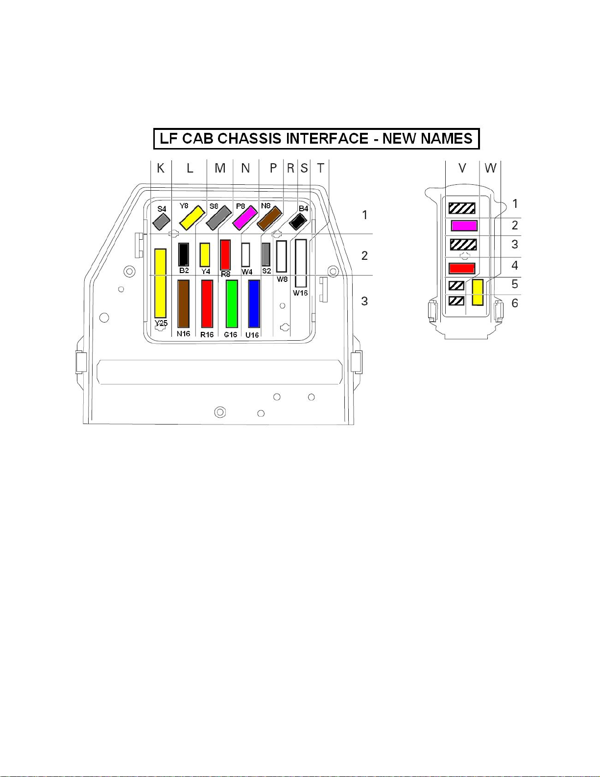
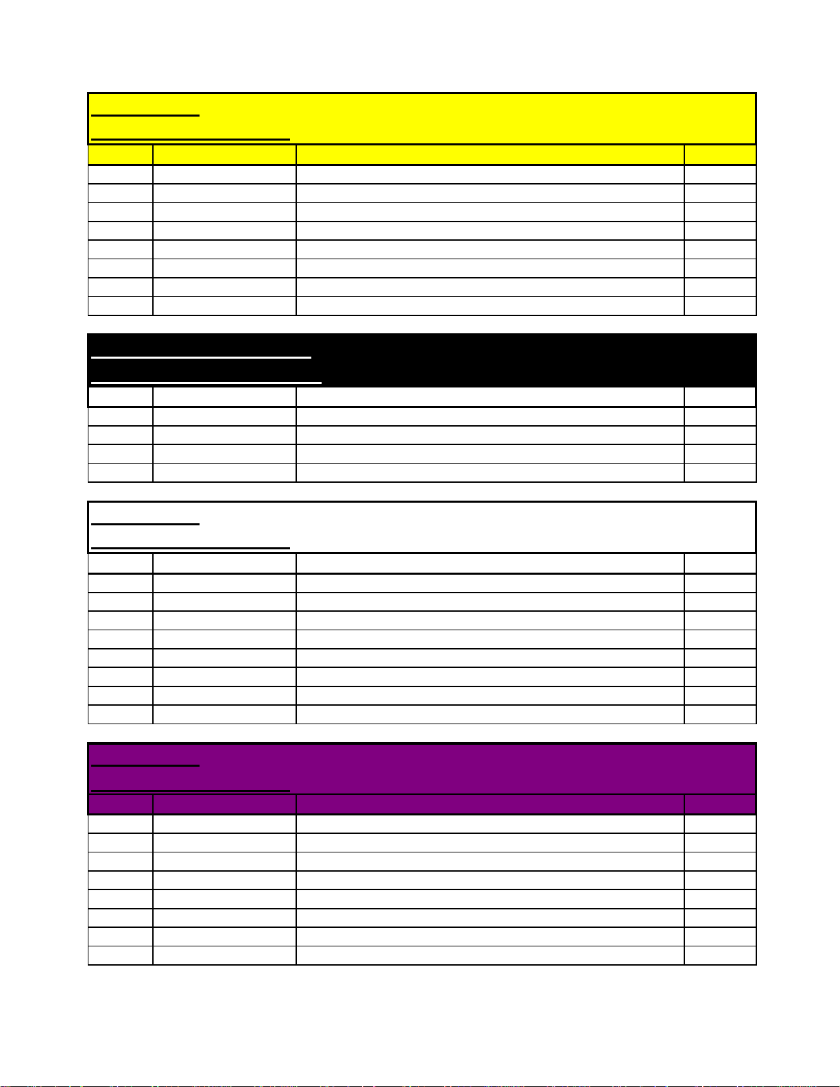
2007 Compliant Models 210 220 - Cab Chassis Interface Definition
(
)
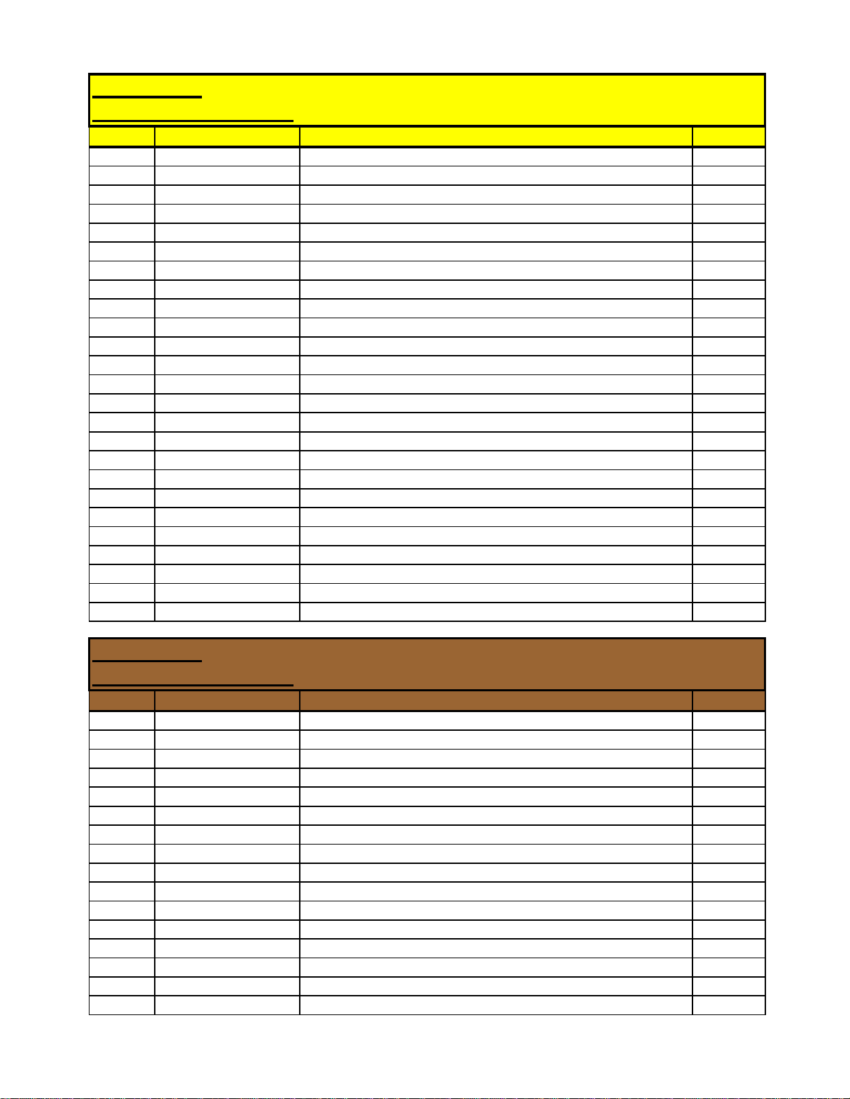
Connector: Yellow 25 pin
Connector Identifier:
Pin No. Schematic page Function DAF no.
A1 M19A Fuel tank sender signal 3503
A2 M19AA Park brake 3402
A3 M05B Reverse Alarm (to buzzer) 5104
A4 M19C Diff lock solenoid 4517
A5 M01E Urea Heater
A6 M19C Brake wear 3406
A7 M05B Reverse light switch +ve - fuse 46 1217
A8 M05A Direction indicator LH truck 2036
A9 M05A Direction indicator RH truck 2037
A10 M04A Tail lamp LH 2170
A11 M04A Tail lamp RH 2169
A12 M04B Rear fog LH/RH 2152
A13 M05B Rear stop lamp LH/RH 4601
B1 M01D ABS trailer pin 2 and 24S trailer pin 6 +ve supply 1356
B2 M05B Reverse alarm from switch 4591
B3 M10A Battery supply +ve - Pin 4 Trailer Socket S 1110
B4 M03A Air drier +ve supply - ignition fuse F39 1240
B5 M03A Heated Sedimenter 5051
B6 M18A Alarm 3659
B7 M19A Direction indicator trailer LH - Pin 3 trailer socket N 2008
B8 M19A Direction indicator trailer RH - Pin 5 trailer socket N 2009
B9 M19C Diff lock switch 3408
B10 M15B ABS trailer warning light 3428
B11 M19AA Cab lock down 3412
B12 M10A Body light 2155
Y25
only if a design requirement
1665
Connector: Brown 16 pin
Connector Identifier:
Pin No. Schematic page Function DAF no.
A1 M19A Air 2 transducer supply 3639
A2 M19A Air 1 transducer ground 3638A
A3 M19A Air 1 transducer supply 3639A
A4 M19A Air 1 transducer signal 3640
A5 M06A Tachograph sender -ve (pin 2 sender unit) 3020
A6 M06A Tachograph sender +ve (pin 1 sender unit) 3021
A7 M06A Tachograph sender signal 1 (pin 4 sender unit) 3018
A8 M06A Tachograph sender signal 2 (pin 3 sender unit) 3019
B1 M19A Gearbox protection solenoid range change 4030
B2 M18A Alarm 3660
B3 M19AA Gearbox neutral switch 4721
B4 M16A PTO solenoid output VIC 4596
B5 M03A W.I.F. warning light 5049
B6 N/C
B7 M19A Air 2 transducer ground 3638
B8 M19A Air 2 transducer signal 3641
N16
(5/08) PM618018 Page 1 of 6
2007 Compliant Models 210 220 - Cab Chassis Interface Definition
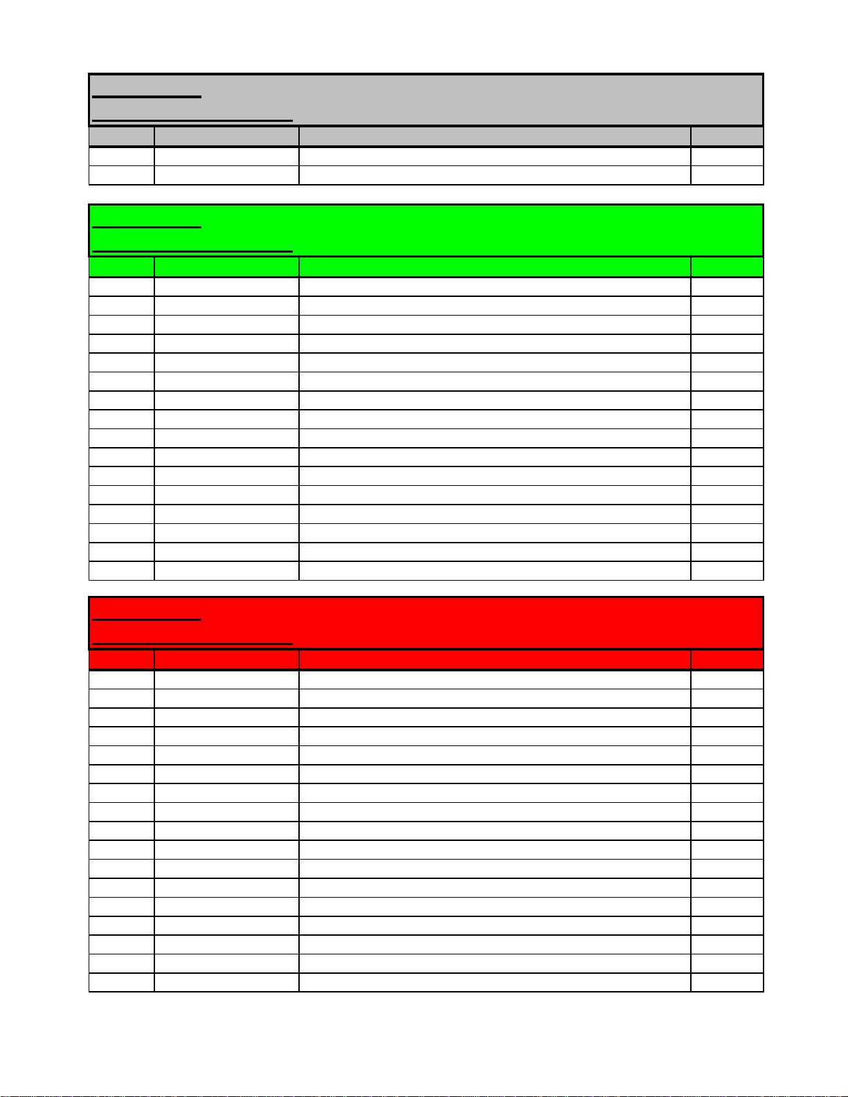
Connector: Grey 2 pin
Connector Identifier:
Pin No. Schematic page Function DAF no.
1 M02B Starter solenoid 4009
2 M15B Trailer ABS 1119
S2
Connector: Green 16 pin
Connector Identifier:
Pin No. Schematic page Function DAF no.
A1 M04E Headlamp levelling pin 1 to motor 3 4953
A2 M04E Headlamp levelling pin 2 to motor 1 2169
A3 M04C Ground
A4 M04C Ground
A5 M04C Ground
A6 M04B Front Fog Lamps 2142
A7 M04C Front Driving Lamps 2122
A8 N/C
B1 M04B/BB Headlamp dip beam LH 2114
B2 M04B/BB Headlamp dip beam RH 2113
B3 M04B/BB Headlamp main beam LH 2122B
B4 M04B/BB Headlamp main beam RH 2122A
B5 M05A Horn 4535
B6 M04A Front side lamps LH & RH 2169
B7 M05A Direction indicator LH 2006
B8 M05A Direction indicator RH 2007
G16
Connector: Red 16 pin
Connector Identifier:
Pin No. Schematic page Function DAF no.
A1 M20A/B/C/D ABS rear sensor LH - ecu pin 14 4629
A2 M20A/B/C/D ABS rear sensor LH - ecu pin 11 4628
A3 M20A/B/C/D ABS rear sensor RH - ecu pin 18 4631
A4 M20A/B/C/D ABS rear sensor RH - ecu pin 17 4630
A5 M20A/B/C/D ABS front sensor LH - ecu pin 15 4621
A6 M20A/B/C/D ABS front sensor LH - ecu pin 12 4620
A7 M20A/B/C/D ABS front sensor RH - ecu pin 13 4623
A8 M20A/B/C/D ABS front sensor RH - ecu pin 10 4622
B1 M20A/B/C/D ABS rear valve LH inlet - ecu pin 2 4641
B2 M20C/D ABS rear valve LH outlet - ecu pin 5 4640
B3 M20C/D ABS rear valve RH inlet - ecu pin 8 4643
B4 M20A/B/C/D ABS rear valve RH outlet - ecu pin 9 4642
B5 M20A/B/C/D ABS front valve LH inlet - ecu pin 3 4633
B6 M20B/C/D ABS front valve LH outlet - ecu pin 6 4632
B7 M20B/C/D ABS front valve RH inlet - ecu pin 1 4635
B8 M20A/B/C/D ABS front valve RH outlet - ecu pin 4 4634
R16
N/C
(5/08) PM618018 Page 2 of 6
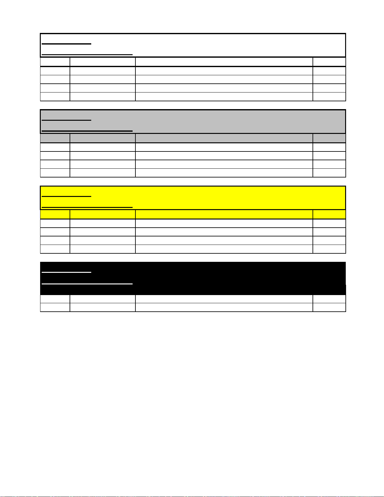
2007 Compliant Models 210 220 - Cab Chassis Interface Definition
p
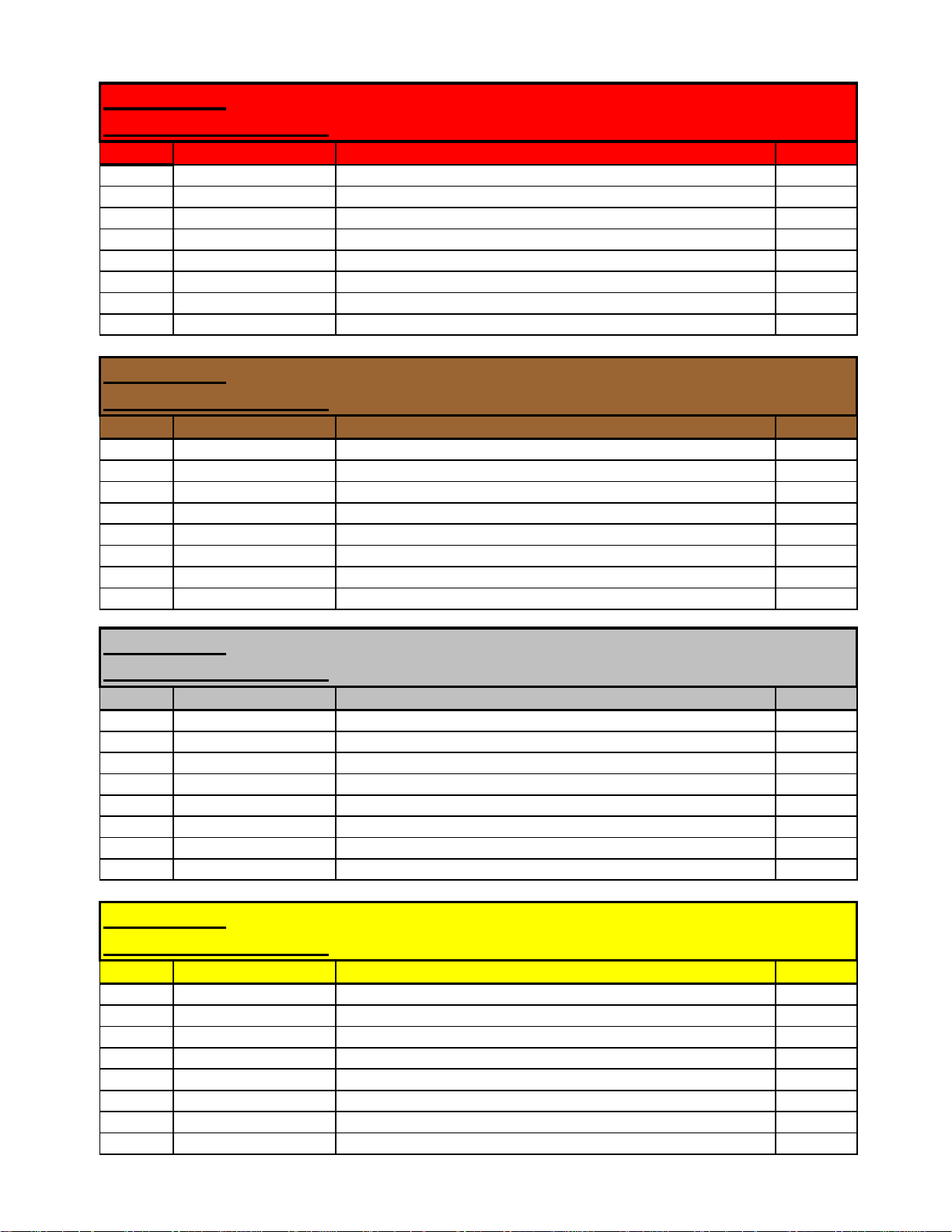
Connector: Red 8 pin
Connector Identifier:
Pin No. Schematic page Function DAF no.
1 M02A Isolation Switch - A5 1380
2 M02A Isolation Switch - A4 4179
3 M02A Battery isolation remote operation - A1 4176
4 M02A Battery isolation remote operation - A2 4177
5 M01CC Battery isolation before battery master isolation switch 1000
6 N/C
7 N/C
8 N/C
R8
Connector: Brown 8 pin
Connector Identifier:
Pin No. Schematic page Function DAF no.
1 M27A CAN H - vcan 3701E
2 M27A CAN L - vcan 3700E
3 M01E Dosing Unit KL15 4265
4 M01E Dosing Unit KL30 1640
5 M27A Engine +ve supply fused battery 1177
6 M27A Engine +ve supply ignition 1211
7 M17B Air conditioning compressor +ve supply 5055
8 M01C Alternator W/L 1020
N8
Connector: Grey 8 pin
Connector Identifier:
Pin No. Schematic page Function DAF no.
1 M30A Switch Wire - Dashboard X003
2 M30A Switch Wire - Dashboard X004
3 M30A Switch Wire - Dashboard X005
4 M30A Switch Wire - Dashboard X006
5 M30A Switch Wire - Headershelf X007
6 M30A Switch Wire - Headershelf X008
7 M30A Switch Wire - Headershelf X009
8 M30A Switch Wire - Headershelf X010
Connector: Yellow 8
Connector Identifier:
Pin No. Schematic page Function DAF no.
1 M25B KL30 supply - Automatic/Automated Gearbox 1163
2 M25B KL15 supply - Automatic/Automated Gearbox 1302
3 M25B Ground
4 M25B Allison Selector Direction Sense 5728
5 M25B MD3060 AGC Pin 43 4595
6 M25B MD3060 AGC Pin 30 5701
7 M25B MD3060 AGC Pin 1 & 17 5646
8 M25B MD3060 AGC Pin 45 5649
S8
Allison Gearbox MD3060
Y8
(5/08) PM618018 Page 3 of 6
2007 Compliant Models 210 220 - Cab Chassis Interface Definition
p
Connector: Yellow 8
Connector Identifier:
Pin No. Schematic page Function DAF no.
1 M25A/C KL30 supply - Automatic/Automated Gearbox 1163
2 M25A/C KL15 supply - Automatic/Automated Gearbox 1302
3 M25A/C Ground
4 N/C
5 M25C AsTronic gearbox module - ZF CAN - A5 3731
6 M25C AsTronic gearbox module - ZF CAN - A2 3732
7 N/C
8 N/C
Allison 1000/2000 - AsTronic Lite
Y8
Connector: Black 4 pin
Connector Identifier: B4
Pin No. Schematic page Function DAF no.
1 M17C Auxiliary Cab Heater Pump 4935
2 M17C Auxiliary Cab Heater Pump 4936
3 N/C
4 N/C
Connector: White 8 pin
Connector Identifier:
Pin No. Schematic page Function DAF no.
1 M27A Throttle pedal +ve supply - engine ecu pin J2-22 4677
2 M27A Throttle pedal signal - engine ecu pin J2-9 4679
3 M27A Throttle pedal common - engine ecu J2-23 4678
4 M27A Throttle pedal on-idle switch - engine ecu pin J2-11 4681
5 M27A Throttle pedal off-idle switch - engine ecu pin J2-1 4166
6 M27A Throttle pedal idle common - engine ecu pin J2-34 4680
7 N/C
8 M02A Grid Heater Warning 4014
W8
Connector: Purple 8 pin
Connector Identifier:
Pin No. Schematic page Function DAF no.
1 M28A/AA ECAS height sensor RH - ecu pin 7 4736
2 M28A/AA ECAS height sensor LH - ecu pin 19 4739
3 M28A/AA ECAS height sensor common - ecu pin 18 9009
4 M28A/AA ECAS valve RH - ecu pin 20 4742
5 M28A/AA ECAS valve LH - ecu pin 8 4741
6 M28A/AA ECAS valve exhaust - ecu pin 21 4740
7 N/C
8 N/C
P8
(5/08) PM618018 Page 4 of 6
2007 Compliant Models 210 220 - Cab Chassis Interface Definition
Connector: White 4 pin
Connector Identifier:
Pin No. Schematic page Function DAF no.
1 M18A Alarm Siren Pin 3 1229
2 M18A Alarm Siren Pin 2 3653
3 M18A Alarm Siren Pin 1 GROUND
4 N/C
P4
Connector: Grey 4 pin
Connector Identifier:
Pin No. Schematic page Function DAF no.
1 M11A Windscreen washer pump 5161
2 M11A Ground
3 Headlamp wash pump (not required at present)
4 N/C
S4
Connector: Yellow 4 pin
Connector Identifier:
Pin No. Schematic page Function DAF no.
1 M20C ASR valve - ecu pin 7 4578
2 M20C ASR valve - ecu pin 16 5060
3 N/C
4 N/C
Y4
Connector: Black 2 pin
Connector Identifier:
Pin No. Schematic page Function DAF no.
1 N/C
2 N/C
B2
(5/08) PM618018 Page 5 of 6
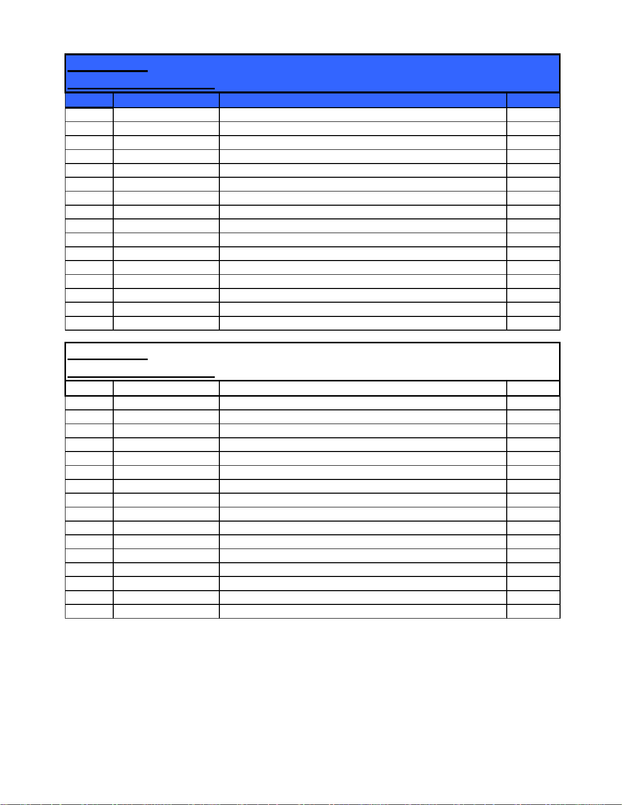
2007 Compliant Models 210 220 - Cab Chassis Interface Definition
Connector: Blue 16 pin
Connector Identifier:
Pin No. Schematic page Function DAF no.
A1 N/C
A2 N/C
A3 N/C
A4 N/C
A5 N/C
A6 N/C
A7 N/C
A8 N/C
B1 N/C
B2 N/C
B3 N/C
B4 N/C
B5 N/C
B6 N/C
B7 N/C
B8 N/C
U16
Connector: White 16 pin
Connector Identifier:
Pin No. Schematic page Function DAF no.
A1 M22A FAN 'Stop' Lamp 3725
A2 M10A PTO status 3524
A3 M22A FAN 'Warning' Lamp 3726
A4 M30A Engine Running 3003
A5 M30A FAN K-Line 3646
A6 M30A Remote PTO 3420
A7 M30A Ignition Control Fuse - F35 2161
A8 M30A Cab lock down 3412
B1 M30A Ground
B2 M30A Ground
B3 M30A Enable ESC 3143
B4 M30A N1 ESC 3144
B5 M30A N2 ESC 3145
B6 M30A N3 ESC 3146
B7 M06A Tachograph speed signal B7 3514
B8 M30A Battery Control Fuse - F50 1600
W16
(5/08) PM618018 Page 6 of 6

Electrical Schematics for Model 210 and 220
PM618018
The content of the pages identified below is generic and not specific to Model 210/220 built after
January 1, 2008. When working on the vehicle it is likely that terminated harnesses will be
encountered where either an available option has not been specified or a feature is not available on
the vehicle.
Page No. System/Component
M00 Electrical schematic information
M01C Supply battery
M01CC Supply battery (with isolator)
M01D Supply fuses
M01E Supply fuses (additional)
M02A Grid heater / remote battery isolator
M02B Starter
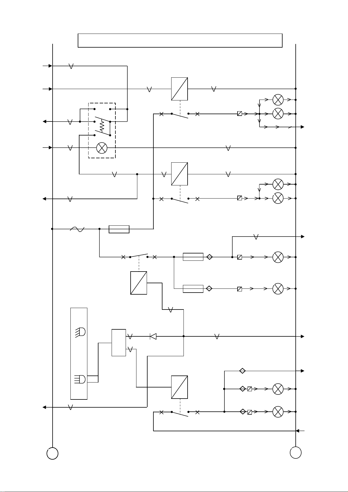
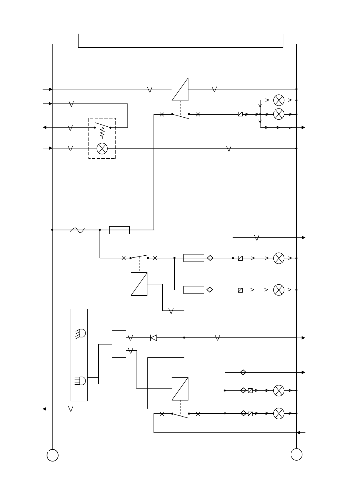
M03A Heated sedimenter / Air drier / WIF (water in fuel)
M04A Lighting
M04B R. fog / F. fog / Main / Dip beam
M04BB R. fog / Main / Dip beam
M04C Driving lamps
M04D Daytime running lamps
M04E Headlamp levelling
M05A Horn / Indicators
M05B Stop / Reverse lights
M05C Rotating beacons

M06A Tachograph / Speedo
PM618018
M07A Diagnostics
M08B Central locking
M08C Electric windows / sun roof
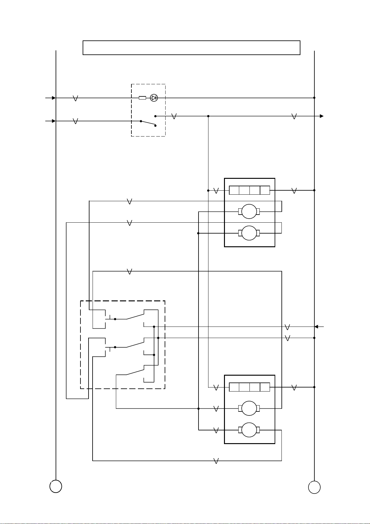
M09A LHD heated & steerable mirrors
M09B RHD heated & steerable mirrors
M10A Interior & body light
M11A Wiper, wash circuit
M14A Accessories LHD
M14AA Accessories RHD
M14B Heated wind screen / seat
M15A Trailer connections
M15B Trailer ABS
M16A Power Take Off
M17B Heater & aircon
M17C Auxiliary cab heater
M18A Alarm
M18B Immobiliser
M19A VIC
M19AA VIC (continued)
M19B DIP / MMI (MCS)

M19C Brake wear / Diff lock
PM618018
M19D BBM
M20A ABS version E 4S2M
M20B ABS version E 4S3M
M20C ABS / ASR version E
M20D ABS version E 4S4M
M21A Telephone
M22A FAN model
M23A Steering wheel (without air bag)
M23BAA Steering wheel (With air bag)
M24A Air bag / Pre-belt tensioner
M25A Allison 2100 Auto gearbox
M25B Allison 3000 Auto gearbox
M25C ZF As-Tronic gearbox
M27A Engine ECU CM2150
M28A ECAS (dual sensor)
M28AA ECAS (single sensor)
M30A Additional wiring
M31A Regeneration
NELC863
y
Electrical Schematics for 2007 Compliant Models 210 and 220
05/2008
page 1 of 57
PM618018
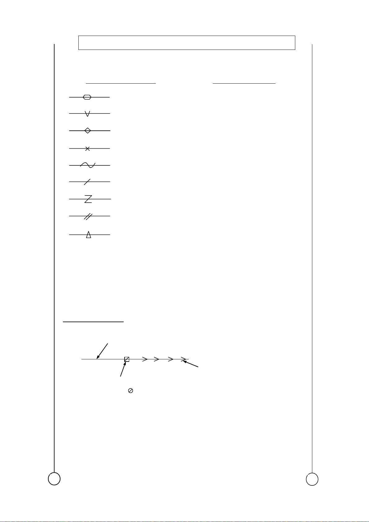
Electrical Schematic Information
Cable Size Denotations
0.35 sq. mm
0.5 sq. mm
1.0 sq. mm
2.0 sq. mm
3.0 sq. mm
4.5 sq. mm
7.5 sq. mm
10.0 sq. mm
16.0 sq. mm
Cable sizes and twisting for I-CAN,
V-CAN and D-CAN are 0.5 sq. mm
cable size and 40 twists/ metre
DAF – Wire Colours
1000 – 1999 = Red
2000 – 2999 = Yellow
3000 – 3999 = Blue
4000 – 6999 = Grey
Not marked or
9000 – 9499 = White
V CAN wiring colours: High = Blue
Low = Yellow
I CAN wiring colours: High = Grey
Low = Yellow
D CAN wiring colours: High = Green
Low = Yellow
General Information
Denotes cab wiring
Y25-B6
Denotes chassis wiring
Indicates Cab-Chassis connector
at Zone 1 (
Zone 2)
Y25 = Yellow connector 25 way
+
B6 = Cavit
No.
-
M00
NELC863
N
y
Electrical Schematics for 2007 Compliant Models 210 and 220
page 2 of 57
05/2008
PM618018
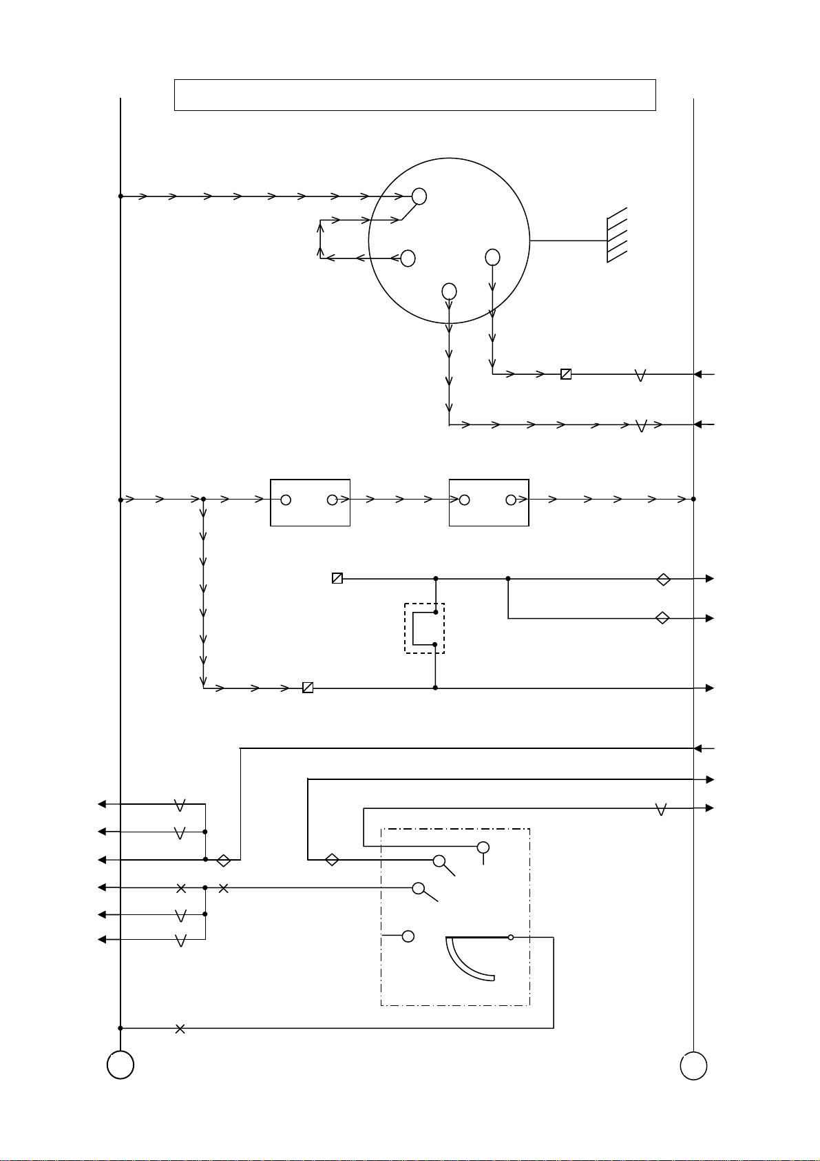
Supply Batter
1000
1000
A500
+ -
B
+
G
+15
+ -
A500
A502
L
8-8
1020
1211
M19AA
M27A
M19AA
M01E
M19AA
M24A
M19AA
M01D
M19AA
M14A/AA
M19AA
M14B
M19AA
M21A
4001
4001
4001
1130
1130
1130
R8-5
Positive stud
Cab-Chassis interface
G766
1000
1000
1000
4001
4001
4002
M17C
M06A
M01D
M02A
M02A
M02B
C841
1000
+
-
M01C
NELC863
N
y
Electrical Schematics for 2007 Compliant Models 210 and 220
05/2008
page 3 of 57
PM618018
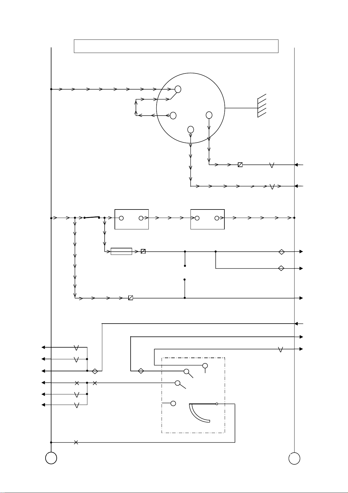
Supply Batter
1000
1000
Batt.
Isol.
A500
+ -
F-2A
E153
R8-5
B
+
G
+15
+ -
A500
A502
L
8-8
1020
1211
1000
1000
M19AA
M27A
M17C
M06A
M19AA
M01E
M19AA
M24A
M19AA
M01D
M19AA
M14A/AA
M19AA
M14B
M19AA
M21A
+
1234
1234
1234
1130
1130
1130
1000
Positive stud
Cab-Chassis interface
C841
1000
1234
4001
4002
M01D
M02A
M02A
M02B
-
M01CC
NELC863
Electrical Schematics for 2007 Compliant Models 210 and 220
page 4 of 57
05/2008
PM618018
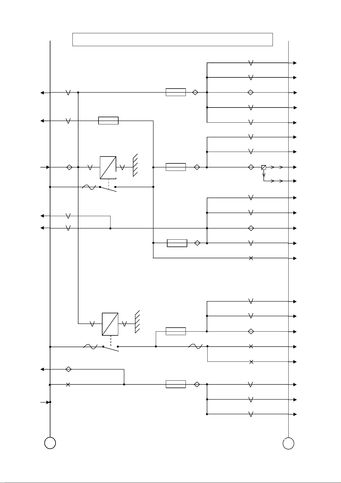
Supply fuses
M19AA
M11A
M19AA M27A
M01C/CC
M07A
M18B
1234
1211
1234
1000
1357
1357
FR01-10A
E035
G015
R1
50A
1010
F46-10A
E018
F1-15A
E282
F16-10A
E143
1217
1217
1217
1217
1217
1356
1356
1356
1357
1357
1357
1357
1010
M11A
M19C
M05B
M03A
M30A
M04D
M05B
Y25-B1
M15B
M15A
M18A
M06A
M20A/B/C
M19AA
M01E
M08B
M01C/CC
1000
1000
1000
+
G353
R2
20A
1358
F39-10A
E091
F34-15A
E411
1240
1240
1240
1358
1358
1666
1666
1666
M23A/AA
M19AA
M03A
M28A/AA
M08C
M17C/CC
M05A
M21A
-
M01D
NELC863
)
N
Electrical Schematics for 2007 Compliant Models 210 and 220
05/2008
page 5 of 57
PM618018
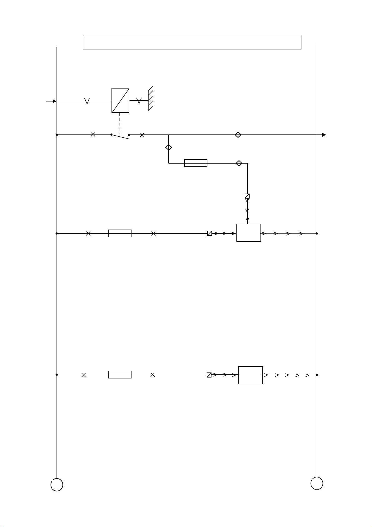
M01C/CC
1234
1000
1000
R004
RX
20A
F06-20A
Supply fuses (Additional
KL30-G/BOX. DOSING
4264
F31-10A
E409
1640
4265
8-4
M25A/B/C
N8-3
B494
1000
E357
F41-20A
E410
1665
Dosing Unit
UREA Heater
Y25-A5
B480
+
-
M01E
NELC863
Electrical Schematics for 2007 Compliant Models 210 and 220
page 6 of 57
05/2008
PM618018
M27A
M19AA
M04A
1000
4014
Grid Heater / Remote Batt. Isol.
GRID HEATER
G014
RELAY CHASSIS
MOUNTED
W8-8
REMOTE BATTERY
ISOLATION SWITCH
A
4014
B
C853
4061
M27A
5
D320
A1
A2
A3
A5
A4
ISOLATION RELAY
7
4178
4177
4176
R8-4
R8-3
-
-
C854
F40-5A
E350
M01C/CC
SHUNT IS FITTED WHEN AN ISOLATION
SWITCH IS
+
NOT REQUIRED
M01C/CC
-
M02A
NELC863
r
Electrical Schematics for 2007 Compliant Models 210 and 220
05/2008
page 7 of 57
PM618018
Starte
M19AA
M01C/CC
4002
1000
1000
50A
R33
G203
4009
S2-1
4173
M19A
L014
+
-
M02B
NELC863
N
Electrical Schematics for 2007 Compliant Models 210 and 220
page 8 of 57
05/2008
PM618018
Heated sedimenter/ Air drier/ W.I.F.
M19AA
M19AA
M19AA
M01D
M19AA
M01D
5049
1240
1217
Y25-B4
R41
16-B5
G201
1
2
3
WATER IN FUEL
AIR DRIER
B042
F692
1000
F19-25A
E164
1190
5051
Y25-B5
FUEL PRE-HEATING
B182
+
-
M03A
g
C
C157
C
C
C159
C
Electrical Schematics for 2007 Compliant Models 210 and 220
05/2008
page 9 of 57
PM618018
Lightin
M19AA
M17C
M19AA
M25B
1000
2102
R05
G000
2170
2170
F2-10A
E283
F3-10A
E284
2169
2169
2169
2170
2170
2170
G16-B6
Y25-A11
Y25-A10
NELC863
M04E
156
Side left
Side right
023
Tail right
M15A
158
Marker L
Marker R
022
Tail left
M19AA
M25A/C
Lighting
switch
M19AA
M04B/BB
1000
2110
2170
2100
2
C622
4
M15A
2170
2170
2170
2170
2170
1
F5-10A
E285
2170
2170
2170
2170
2170
2170
2170
2170
2170
2170
2639
2639
2100
M31A
M19AA
M04B/BB
M05A
M05B
M08B
M08C
M09A/B
M10A
M16A
M19C
M18A
M05C
M02A
M06A
M04B/BB
M19A
M04D
+
-
M04A
NELC863
32
m
Electrical Schematics for 2007 Compliant Models 210 and 220
page 10 of 57
05/2008
PM618018
R. Fog/ F. Fog/ Main/ Dip bea
M04A
M19AA
M19A
M04A
M19A
2639
2168
2150
2170
2140
1000
5
3
6
A
2140
1
C727
2
B
F8-15A
2141
R. Fog
R10
F. Fog
R9
G005
G004
2152
2142
Y25-A12
G16-A6
C024
C025
C008
C009
2152
M15A
M04A
2110
C775
E009
White
R11
Dip
2154
G001
D610
2120
2112
F12-10A
F13-10A
Main
R12
E004
E005
G002
2110
2114
2113
2122
2122
2122
G16-B1
G16-B2
2121
M19AA
C000
LH
C001
RH
M04D
M04C
C002
LH
G16-B3
C003
RH
G16-B4
M04C
+
-
M04B
32
Electrical Schematics for 2007 Compliant Models 210 and 220
05/2008
page 11 of 57
PM618018
M19AA
M04A
M19A
M04A
2168
2639
2150
2170
NELC863
R. Fog/ Main/ Dip beam
R. Fog
R10
G005
C024
2152
Y25-A12
5
1
C773
B
A
C025
2152
M15A
M04A
1000
2110
C775
F8-15A
E009
White
2141
R11
Dip
2154
2112 2114
G001
D610
2120
F12-10A
F13-10A
Main
R12
E004
E005
2110
G002
2113
2122
2122
2122
G16-B1
G16-B2
2121
M19AA
C000
LH
C001
RH
M04D
M04C
C002
LH
G16-B3
C003
RH
G16-B4
M04C
+
-
M04BB

NELC863
Electrical Schematics for 2007 Compliant Models 210 and 220
page 12 of 57
05/2008
PM618018
Driving Lamps
M04B/BB
1000
2122
F14-15A
E006
G16-A7
G16-A3
G16-A4
C006
C007
2121
2122
M04B/BB
M19AA
+
G16-A5
-
M04C

Electrical Schematics for 2007 Compliant Models 210 and 220
05/2008
page 13 of 57
PM618018
M04A
2100
D784
Daytime Running Lights
2648
D785
G735
NELC863
1356
M01D
M04B/BB
2110
+
-
M04D

NELC863
g
Electrical Schematics for 2007 Compliant Models 210 and 220
page 14 of 57
05/2008
PM618018
Headlamp Levellin
G16-A1
G16-A2
3
4
Control
2
1
C764
B129
3
M
1
2
+
Actuator LH
3
1
Actuator RH
M
B130
2
M04A
-
M04E

NELC863
Electrical Schematics for 2007 Compliant Models 210 and 220
05/2008
page 15 of 57
PM618018
Horn, Indicators
M19AA
M19A
1000
2001
C775
F26-15A
E019
Purple
White
4535
2
4979
6 7 4
Horn
G16-B5
B401
M19AA
M19A
M19AA
M19A
M19AA
M19A
M19AA
M19A
M19AA
M19A
M19AA
M19A
2002
2007
2037
2006
2036
2003
2029
DI Right
G16-B8
C015
Front
C017
Side
Y25-A9
C019
Rear
G16-B7
C014
Front
C016
Side
Y25-A8
C018
Rear
DI Left
6
5
2
7
1
2036
1666
2170
M01D
M04A
A B
C765
+
Hazard
-
M05A

NELC863
Electrical Schematics for 2007 Compliant Models 210 and 220
page 16 of 57
05/2008
PM618018
Stop/ Reverse lights
M19AA
M01D
1356
1000
G036
R14
Stop
4602
F27-10A
E013
C814
5 1
4602
4601
4601
51044591
Footbrake
switch
E511
Y25-A13
Y25-A3
C020
C021
4602
M19A
M15A
M28A/AA
M19AA
M04A
M19AA
M25C
M19AA
M01D
4591
1217
2170
Y25-A7
A B
Y25-B2
Reverse
E501
4591
C026
C027
M15A
+
-
M05B

NELC863
Electrical Schematics for 2007 Compliant Models 210 and 220
05/2008
page 17 of 57
PM618018
Rotating Beacon
C144
C145
2018
M08C
M04A
1154
1000
2170
F20-20A
E142
C716
1154
75
+
-
M05C

NELC863
4
_
N
N
N
N
Electrical Schematics for 2007 Compliant Models 210 and 220
page 18 of 57
05/2008
PM618018
Tachograph / Speedo
F533
M01C/CC
B525
1 5
2
3
6
7
16-A5
F25-5A
E023
16-A6
5 5
2
6
+
1 2
16-A7
11271000
2 2
33
77
5
16-A8
111
5
66
7
3
9001
9025
2170
M04A
M28A/AA
+
8
4
D
4
8
A DUMMY TACHOGRAPH
(SPEEDO) HAS THE SAME
WIRING AS AN
OPERATIONAL TACHOGRAPH
3514
8
8
BC
44
A
3700A
CAN L
V CAN
3701A
1357
CAN H
M01D
W16-B7
M22A
-
M06A

NELC863
m
Electrical Schematics for 2007 Compliant Models 210 and 220
05/2008
page 19 of 57
PM618018
M01D
1357
Diagnostics
3425
9107
4732
4732
3646
3646
3646
3646
M20A/B/C
M28A/AA
M19A
M22A
M24A
M08B
M18A
CAN L
CAN H
M17C
M18A
M18A
M28A/AA
3782
3783
3037
1000
1229
1229
1229
F33-10A
E053
1 2 3
9 10 11
1229
4
12 13 14 15 16
5 6
7 8
A100
120 oh
B468
2
1
FMS
Connector
4733
M19B
+
-
M07A

NELC863
g
r
r
Electrical Schematics for 2007 Compliant Models 210 and 220
page 20 of 57
05/2008
PM618018
M01D
M07A
M19AA
1000
3646
3647
F45-10A
E198
Central Lockin
1181
4538
4537
9 10 11 12 13 14 15 16
1 2 3 4 5 6 7 8
D916
5062
5061
W8-1
W8-3
M18A
M10A
M04A
3647
1107
2170
R8-6
B199
Drivers
Doo
R8-5 R8-7
1
L
2
U
3
4
5061
5118
A
B
1
2
L
3
U
4
Passengers
Doo
B200
+
7
1
C774
3
-
M08B

NELC863
r
Electrical Schematics for 2007 Compliant Models 210 and 220
05/2008
page 21 of 57
PM618018
M05C
M04A
1154
2170
2170
1208
1208
C736
4
6
3
5
7
1
Drivers Door
C866
1
7
5
9
2
6
4
C865
Electric Windows/ Sun Roof
4760
B009
4761
4528
B003
4529
2170
Passenger Doo
C864
M
M
Sun Roof
M09A/B
M01D
M09A/B
1358
1208
+
1208
1208
1208
1
7
9
2
4
W8-2
F24-20A
E044
1
7
4521
5
9
4520
6
2
5
6
4
4524
B004
4525
M
-
M08C

NELC863
Electrical Schematics for 2007 Compliant Models 210 and 220
page 22 of 57
05/2008
PM618018
LHD Heated and Steerable Mirrors
C867
M04A
M08C
2170
1208
4772
4770
4771
7
5
4532
B017
M
M
B005
M14B
H
V
10
4
5
8
POS G
POS D
7
C556
4773
3
9
B018
4774
M
M
B006
H
V
1208
M08C
+
-
M09A
NELC863
Electrical Schematics for 2007 Compliant Models 210 and 220
05/2008
page 23 of 57
PM618018
RHD Heated and Steerable Mirrors
C867
M04A
M08C
2170
1208
4771
4773
4772
7
5
4532
B018
M
M
B006
M14B
H
V
10
4
5
8
POS G
POS D
7
C556
4770
3
9
B017
4774
M
M
B005
H
V
1208
M08C
+
-
M09B

t
Electrical Schematics for 2007 Compliant Models 210 and 220
page 24 of 57
05/2008
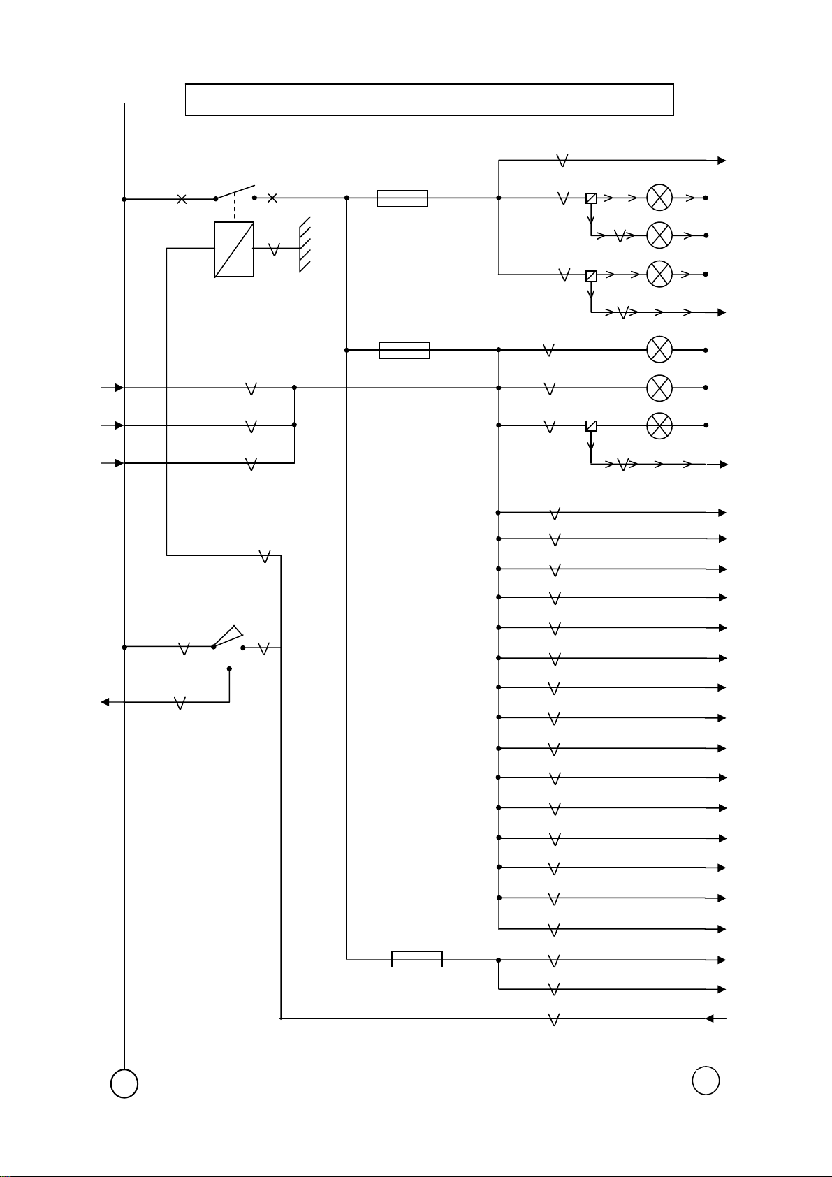
PM618018
M19AA
1000
2610
F37-15A
E028
NELC863
Interior and body ligh
Interior light 1
1107
C119
Interior light 2
2610
M08B
M19AA
M18A
M18A
M19AA
1107
2600
1107
2600
2647
1107
2647
1107
E514
E515
C120
Drivers door
2600
R8-8
C062
Step lights
Passenger door
R8-2
C063
C110
1107
C111
F43-10A
E052
1110
C725
1 5
A
M04A
1000
2170
+
Body lamp
LH bunk light
RH bunk light
Y25-B3
M15A
2155
2155
B
Y25-B12
C071
M19AA
-
M10A

NELC863
6
5
3
7
t
Electrical Schematics for 2007 Compliant Models 210 and 220
05/2008
page 25 of 57
PM618018
M01D
1234
1000
F32-15A
E025
Wiper, wash circui
G354
R3
1204
1205 1205
5161
4508
S4-1
B001
S4-2
P
M01D
1217
2
4506
C842
4
4507
Y8-1
Y8-4
B000
M
Y8-2
1
4509
Y8-3
1205
Y8-5
G008 R25
4504
5161
4502
M19A
M19A
M19A
+
-
M11A

NELC863
Electrical Schematics for 2007 Compliant Models 210 and 220
page 26 of 57
05/2008
PM618018
M01C/CC
1130
F30-20A
E026
RADIO
B023
Accessories - LHD
B
4543
4541
1 3 5 7
2 4 6 8
B025
A
1 3 5 7
2 4 6 8
1153
24-12V
Conv
1108
9 6 7
12V 5
4
24V
3 2 1
B024
D579
4542
1
2
3
4540
1153
5400
5401
5402
Headershelf
M21A
M21A
M21A
1
2
M19AA
1105
1000
F23-10A
E027
1106
+
-
M14A

NELC863
Electrical Schematics for 2007 Compliant Models 210 and 220
05/2008
page 27 of 57
PM618018
M01C/CC
1130
F30-20A
E026
RADIO
B023
Accessories - RHD
B
4542
4540
1 3 5 7
2 4 6 8
B025
A
1 3 5 7
2 4 6 8
1153
24-12V
Conv
1108
9 6 7
12V 5
4
24V
3 2 1
B024
D579
4543
1
2
3
4541
1153
5400
5401
5402
Headershelf
M21A
M21A
M21A
1
2
M19AA
1105
1000
F23-10A
E027
1106
+
-
M14AA

NELC863
t
t
Electrical Schematics for 2007 Compliant Models 210 and 220
page 28 of 57
05/2008
PM618018
Heated Windscreen/ Sea
Heated Windscreen
Screen
1000
F61-50A
E299
1603
30
5436
87
G397
resistance
B371
M09A/B
M01C/CC
4532
1130
1000
R6
G355
F17-20A
85
R48
50A
Timing 12 minutes
Heated Driver Seat
1227
86
B032
E039
+
Drivers Sea
-
M14B

NELC863
Electrical Schematics for 2007 Compliant Models 210 and 220
05/2008
page 29 of 57
PM618018
Trailer Connections
M04A
M19A
M05B
M19A
M04A
2169
2009
4601
2008
2170
A000
6
5
1
7
4
24N
A001
1
2
3
6
5
2
7
3
4
2152
M04B/BB
4591
M05B
1110
M10A
3651
M18A
24S
+
-
M15A

NELC863
Electrical Schematics for 2007 Compliant Models 210 and 220
page 30 of 57
05/2008
PM618018
Trailer ABS
M01D
1000
1356
F36-20A
E009
A004
1119
S2-2
2
1
7
6
3
4
5
3428
Y25-B10
M19AA
+
-
M15B

NELC863
A
N
Electrical Schematics for 2007 Compliant Models 210 and 220
05/2008
page 31 of 57
PM618018
PTO
M19AA
M04A
M19AA
M19A
M19D
M19AA
M19AA
M19AA
M19D
2170
4594
4594
3524
3524
C750
5
W16-A2
PTO
B
1
PTO status
M19AA
M19A
M19D
4596
3524
4596
PTO Solenoid
16-B4
B245
+ -
M16A

NELC863
r
N
Electrical Schematics for 2007 Compliant Models 210 and 220
page 32 of 57
05/2008
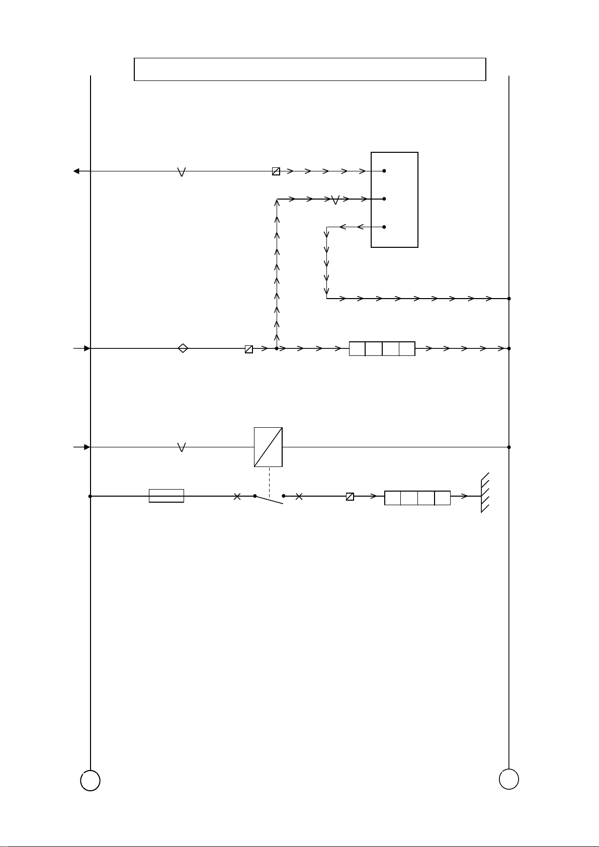
PM618018
M01D
F18-15A
E031
7
8
M
Heater and Air con.
Heate
B377
M21A
2622
5
M19AA
M19A
6
Air Con.
Switch
4
2
1
-
+
-
8-7
Air Conditioning
-
M17B

NELC863
r
56
6664765
5
7
98046604766
5
7
Electrical Schematics for 2007 Compliant Models 210 and 220
05/2008
page 33 of 57
PM618018
M04A
2170
E586
Auxiliary Cab Heate
M T W T F S S
88:88
4 12 11 1 10 3 5 6 2 8 7 9
C926
4660
7 5
W/L
10
2
11
D521
1
11
4 9 6 1 8 7 3 2
11
4
3
8
4
5
2
7
1
10
1666
4935
B122
4936
5117
B4-1
P
B4-2
3037
M07A
M01D
M18A
F29-10A
M01C/CC
E114
+
-
M17C

NELC863
m
N
A
N
Electrical Schematics for 2007 Compliant Models 210 and 220
page 34 of 57
05/2008
PM618018
Alar
D911
A7
A8
2003
M19A
M19AA
M01D
M19AA
M07A
LED
Siren
1229
D715
B338
1
2
3
2
1
B8
A4
A9
B5
A2 B15
B9
B11
3482
B14
B10
B6
W4-1
W4-2
W4-3
3653
B3
B4
B16
B21
B20
3652
34121357
3646
5117
2600
2647
3659
3660
3647
3566E
3565E
Y25-B6
16-B2
I CAN
M19AA
M19AA
M07A
M17C
M10A
M10A
M08B
CAN H
CAN L
Radar
sensor
Application
connector
M15A
M19AA
2170
1229
F686
2
4
1
Radar
1
5
2170
C835
2
7
C836
B
B13
sensor
exclu
3658
3654
3649
3651
B7
A12
A10
Trail
door
exclu
A070
5
16-B6
B2
3657
1
5
+ -
M04A
M07A
M18A

NELC863
r
Electrical Schematics for 2007 Compliant Models 210 and 220
05/2008
page 35 of 57
PM618018
Immobilise
M19AA
M01D
1357
1 2
BLACK
1 2
D912
3
4
3
4
6
5
3700H
CAN L
V CAN
3701H
CAN H
+ -
M18B

NELC863
p
N
N
N
N
N
N
N
Electrical Schematics for 2007 Compliant Models 210 and 220
page 36 of 57
05/2008
PM618018
CAN H
CAN L
E108
E280
E277
M28A/AA
M28A/AA
M24A
M05A
M05A
M05A
M05A
M05A
M05A
M15A
M15A
M05A
M18A
M11A
M11A
M11A
M02B
M05B
F57-15A
F38-15A
F21-15A
Y25-B8
Y25-B7
3701C
3700C
1114
1199
1198
3432
3431
3670
2001
2002
2007
2037
2006
2036
2009
2008
2003
5161
4502
4504
4173
4602
C1
C2
A2
A9
E3
B9
B10
C31
D38
D39
E8
A8
E9
A7
E4
E7
D23
D33
D37
C50
C51
D32
D310
VIC
D18
D20
C46
A5
E5
C44
C4
B5
B23
C7
D12
A01
D31
D21
D16
D11
D35
D34
D3
D13
C10
C12
3566A
3565A
5655
4030
4732
4594
4596
2639
3503
5189
3639
3638
3640
3641
2150
2140
3637
3636
X010
X009
16-B1
Y25-A1
R8-1
R8-3
16-A3
16-A2
16-A4
16-A1
16-B7
16-B8
1
2
F608
F652
F652
F651
B079
CAN H
CAN L
M25C
Gearbox
rotection
M07A
M16A
M16A
M04A
Fuel Level
M17B
Air 1
Transducer
Air 2
Transducer
M04B/BB
M04B
Outside
Temp
M30A
M30A
+
-
M19A

N
N
)
Electrical Schematics for 2007 Compliant Models 210 and 220
05/2008
page 37 of 57
PM618018
M04C
M19C
M01C/CC
M15B
M19B
M19B
M19B
M19B
M19B
M19C
M04B/BB
M10A
M10A
M10A
M10A
M08B
M03A
M30A
M30A
M30A
M30A
M01D
M19D
M04A
2122
3408
1020
3428
5160
9033
3642
3643
3644
3406
2168
2155
2600
2647
2610
3647
5049
3143
3144
3145
3146
1357
1357
2170
VIC (Continued
D310
C6
C34
D28
C32
C22
C23
C24
C25
C26
B17
C40
C9
D1
D22
A4
C13
D8
D09
D05
D06
D07
E1
C14
C15
C8
D36
C49
C35
C30
B16
D26
C17
C18
C19
C33
C42
B14
B12
B06
B03
B04
3701D
V CAN
4721
3402
16-B3
E569
Y25-A2
Y25-B11
F009
4684 1240
E596
Clutch
D CAN
3701D
4014
2114
2622
2622
2622
F000
3412
3412
3420
3725
3726
3652
3157
3524
3783
3782
NELC863
CAN H
CAN L
M02A
M04B/BB
M17B
M14A/AA
M19B
eutral
Park brake
M30A
M18A
Cab lock
M01D
M30A
M22A
M22A
M18A
M30A
M16A
CAN H
CAN L
Instrument
dimming
B
9
A
3
D14
C763
+
-
M19AA

)
Electrical Schematics for 2007 Compliant Models 210 and 220
page 38 of 57
05/2008
PM618018
M19AA
CAN H
M19AA
CAN L
CAN H
M19AA
CAN L
M07A
I CAN
V CAN
F07-10A
E310
3566B
3565B
3701B
3700B
1612
4733
DIP / MMI (MCS
D899
7
5
13
11
1
3
14
12
3701C
3700C
2
NELC863
DIP
CAN H
V CAN
CAN L
M19AA
M19AA
M19AA
M19AA
M19AA
M19AA
5160
9033
3642
3643
3644
2622
1
3
2
4
6
5
MMI (MCS) Switch
D904
-+
M19B

NELC863
k
A
Electrical Schematics for 2007 Compliant Models 210 and 220
05/2008
page 39 of 57
PM618018
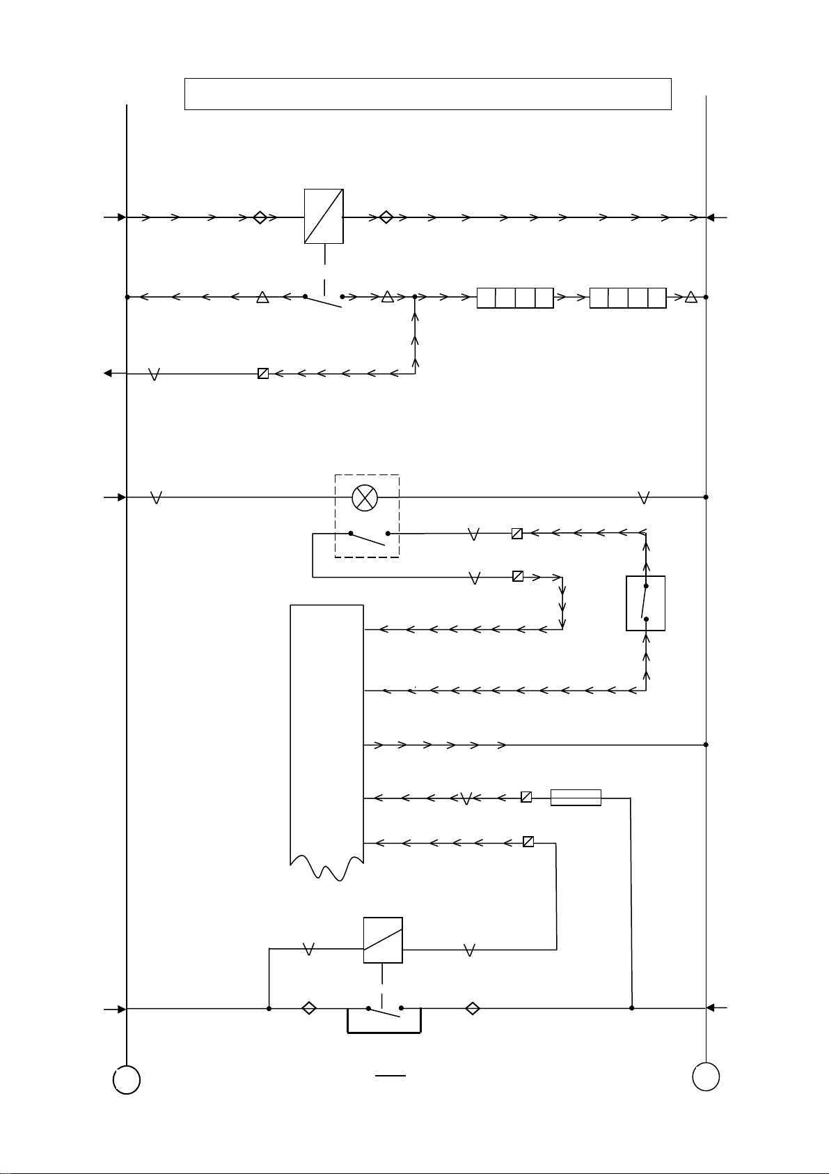
Brake Wear/ Diff Lock
Diff Loc
C748
M19AA
M04A
M19AA
M01D
M19AA
2170
1217
3408
Brake Wear
5
B
1
Y25-B9
F108
3406A
4517
3406B
Y25-A4
F006
DL Switch
Engaged
EP valve
B243
F112
3406C
M19AA
M19AA
3406
Y25-A6
F107
F111
+ -
M19C

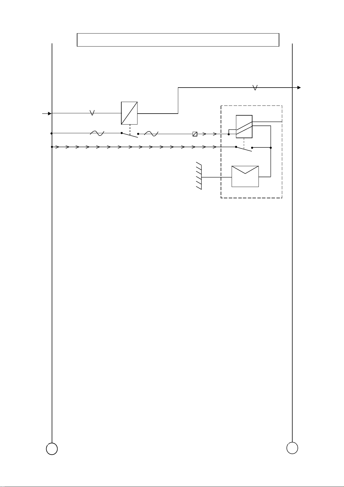
BBM
Electrical Schematics for 2007 Compliant Models 210 and 220
page 40 of 57
05/2008
PM618018
D993
NELC863
M19AA M19AA
M16A
M16A
M16A
F09-15A
E390
1659
1659
1357
4594
4596
3524
A02
A09
C13
C07
A04
C10
A05
C01
3701F
VCAN
CAN H
3839
3838
C22
C23
C26
C24
C02
A01
C17
D04
C09
3700F
4595
5701
5646
5649
CAN L
M25B
M25B
M25B
M25B
+
-
M19D

NELC863
9
Electrical Schematics for 2007 Compliant Models 210 and 220
05/2008
page 41 of 57
PM618018
ABS Version E –4S2M
D329
Modulators
M01D
M07A
CAN L
CAN H
1000
1357
3425
3700G
3701G
F28-15A
E190
V CAN
1187
8
7
5
10
11
1
3
9
4
12
15
10
13
11
14
4633
3
4634
4
4641
2
4642
9
4620
4621
4622
4623
4628
462
R16-B5
R16-B8
R16-B1
R16-B4
R16-A6
R16-A5
R16-A8
R16-A7
R16-A2
R16-A1
F512
F513
F514
B256
A1
B251
A2
A1L
A1R
A2L
4S- 2M
Front L
Front R
Rear L
+
17
18
4630
4631
R16-A4
R16-A3
F515
Sensors
Note:- Wiring to individual
sensors must be twisted to
>/= 30 twists per meter
A2R
Rear R
-
M20A

NELC863
9
Electrical Schematics for 2007 Compliant Models 210 and 220
page 42 of 57
05/2008
PM618018
ABS Version E –4S3M
D329
Modulators
M01D
M07A
CAN L
CAN H
1000
1357
3425
3700G
3701G
F28-15A
E190
V CAN
1187
8
7
5
10
11
1
3
9
4
12
15
10
13
11
14
4633
3
4632
6
4641
2
4642
9
4635
1
4634
4
4620
4621
4622
4623
4628
462
R16-B5
R16-B6
R16-B1
R16-B4
R16-B7
R16-B8
R16-A6
R16-A5
R16-A8
R16-A7
R16-A2
R16-A1
F512
F513
F514
B256
A1L
B251
A2
B257
A1R
A1L
A1R
A2L
4S- 3M
Front L
Front R
Rear L
+
17
18
4630
4631
R16-A4
R16-A3
F515
Sensors
Note:- Wiring to individual
sensors must be twisted to
>/= 30 twists per meter
A2R
Rear R
-
M20B

NELC863
9
Electrical Schematics for 2007 Compliant Models 210 and 220
05/2008
page 43 of 57
PM618018
ABS/ ASR Version E
D329
Modulators
M01D
M07A
CAN L
CAN H
1000
1357
3425
3700G
3701G
F28-15A
E190
V CAN
1187
8
7
5
10
11
1
3
9
4
12
15
10
13
11
14
4635
1
4634
4
4643
8
4642
9
4633
3
4632
6
4641
2
4640
5
4620
4621
4622
4623
4628
462
R16-B7
R16-B8
R16-B3
R16-B4
R16-B5
R16-B6
R16-B1
R16-B2
R16-A6
R16-A5
R16-A8
R16-A7
R16-A2
R16-A1
F512
F513
F514
B257
A1R
B259
A2R
B256
A1L
B258
A2L
A1L
A1R
A2L
4S- 4M
Front L
Front R
Rear L
+
17
18
16
4630
4631
R16-A4
R16-A3
F515
A2R
Rear R
Sensors
4578
7
5060
Note:- Wiring to individual
sensors must be twisted to
Y4-1
Y4-2
>/= 30 twists per meter
B237
ASR
Valve
-
M20C

NELC863
9
Electrical Schematics for 2007 Compliant Models 210 and 220
page 44 of 57
05/2008
PM618018
ABS Version E 4S4M
D329
Modulators
M01D
M07A
CAN L
CAN H
1000
1357
3425
3700G
3701G
F28-15A
E190
V CAN
1187
8
7
5
10
11
1
3
9
4
12
15
10
13
11
14
4635
1
4634
4
4643
8
4642
9
4633
3
4632
6
4641
2
4640
5
4620
4621
4622
4623
4628
462
R16-B7
R16-B8
R16-B3
R16-B4
R16-B5
R16-B6
R16-B1
R16-B2
R16-A6
R16-A5
R16-A8
R16-A7
R16-A2
R16-A1
F512
F513
F514
B257
A1R
B259
A2R
B256
A1L
B258
A2L
A1L
A1R
A2L
4S- 4M
Front L
Front R
Rear L
+
17
18
4630
4631
R16-A4
R16-A3
F515
Sensors
Note:- Wiring to individual
sensors must be twisted to
>/= 30 twists per meter
A2R
Rear R
-
M20D

Electrical Schematics for 2007 Compliant Models 210 and 220
05/2008
page 45 of 57
PM618018
M01D
M17B
CAN L
CAN H
M01C/CC
M14A/AA
M14A/AA
M14A/AA
1666
1201
3565C
3566C
1130
5400
5401
5402
I CAN
Microphone
Telephone
Speaker
Telephone
Base Plate
B471
B476
B479
-
+
NELC863
Telephone
2
1
17
19
3
18
+1
-2
Single core
screened cable
8
24
7
23
5
5418
5399
22
6
1
2
5
14
6
15
9
18
8
17
3
12
11
10
4
5403
5404
5405
5406
5407
5408
5410
5411
5412
5413
5414
5415
5416
5417
5420
Telephone
12
11
14
30
15
31
9
25
10
26
13
29
27
28
16
ECU
B470
+
Telephone
Antenna
-
M21A

NELC863
W
Electrical Schematics for 2007 Compliant Models 210 and 220
page 46 of 57
05/2008
PM618018
46
44
F.A.N.
F.A.N.
ECU
38
37
3712
9036
1
2
3
2622 2622
2622
F696
1
M30A
M30A
M30A
M19AA
M19AA
M06A
M07A
2161
1600
3157
3725
3726
3514
3646
16-A1
W16-A3
W16-A5
45
68
23
63
25
26
56
62
15
61
24
35
49
39
16
30
29
10
3709
3714
3715
3747
2
3748
5186
5185
5184
2
4
FRONT STEERING
3412
1240
REAR STEERING
ABS
SENSOR
ANGLE
F695
ANGLE
F767
B381
F116
OIL LEVEL
SWITCH
3716
19
+
D940
13
5183
5
VALVE BLOCK
6
7
-
M22A

NELC863
g)
Electrical Schematics for 2007 Compliant Models 210 and 220
05/2008
page 47 of 57
PM618018
Steering Wheel (Without Airba
D338
Start
End
On
Off
4
Red
1 2
3
Set
Off
Res
Off
Green
1 2
12
Set+
Set-
3565F
1240
3566F
I CAN
CAN L
M01D
I CAN
CAN H
+
-
M23A

NELC863
g)
Electrical Schematics for 2007 Compliant Models 210 and 220
page 48 of 57
05/2008
PM618018
Steering Wheel (With Airba
D338
M24A
M24A
5171
5170
Start
End
Yellow
1 2
8
Set
Off
Res
Off
Green
1 2
2 1
Set+
Set-
3565F
I CAN
On
Off
Red
1 2
6
7
5
CAN L
1240
3566F
M01D
I CAN
CAN H
-+
M23AA

r
Electrical Schematics for 2007 Compliant Models 210 and 220
05/2008
page 49 of 57
PM618018
Airbag/ Pre-belt Tensione
B360
1 2
NELC863
M19AA
M01C/CC
M19AA
M19A
1234
3670
FR4-10A
E297
5169
5168
1230
5
10
5171
M23AA
7
1
2
11
13
5170
9
3646
M23AA
M07A
3
12
4
14
6
15
+
8
D926
-
M24A

NELC863
Electrical Schematics for 2007 Compliant Models 210 and 220
page 50 of 57
05/2008
PM618018
Automatic Gearbox Allison
1000/ 2000 Series
M19AA
M04A
M19AA
M01E
M19AA
CAN H
2170
4264
F10-10A
E145
F11-10A
E144
3701K
1
2
Locate adjacent to the
heated seat connector
1163
1302
Y8-2
Y8-1
70
10
63
7
28
48
Y8-3
9
69
M19AA
CAN L
3700K
8
Y8-8
AGC
D312
+
-
M25A

Electrical Schematics for 2007 Compliant Models 210 and 220
05/2008
page 51 of 57
PM618018
M04A
CAN-L
2170
3700 J
Automatic Gearbox Allison
MD3060
3
15
NELC863
5
CAN-H
M19AA
M01E
CAN H
4264
3701 J
F10-10A
E145
F11-10A
E144
3701K
1163
1302J
8
SHIFT
SELECTOR
E605
13
12
Y8-1Y8-2
70
11
34
5728
Y8- 4
10
63
7
28
9
69
Y8-3
48
CAN L
M19AA
M19D
M19AA
M19D
3700K
5649
5646
+
Y8-8
Y8-7
8
1
17
AGC
43
30
Y8-5
4595
M19D
5701
M19D
Y8-6
D312
-
M25B

Electrical Schematics for 2007 Compliant Models 210 and 220
page 52 of 57
05/2008
PM618018
M19AA
M01E
3
6
C943
+/- Switch
5
A
C942
M/A Switch
4264
7
1
2
8
B A
7
1
B
F10-10A
E145
F11-10A
E144
Gearbox Automated
As-tronic Lite
3808
3792
3791
3790
3739
3788
3789
1163
1302
D11
D12
D10
C11
C9
D14
D13
C2
C1
C17
C18
D2
D3
D4
D5
D6
D15
D1
C6
C8
E-Module
D996
3732
3802
3803
3804
3805
3806
3807
3808
3731
Rotary
switch
E602
1 RC
3 R
5 N
2 D
4 DC
6 VM
8 VP
7 L
2170
NELC863
M04A
M19AA
M19A
F768
F769
Travel
sensor
shift
Travel
sensor
select
F139
25A
Exxx
1
2
1
2
Fluid level
F15-10A
E016
Y8-1
1216
5655
Y8-2
A9
A12
A15
B1
C3
C1
C6
C2
C12
C7
A5
A2
A18
A21
B2
A7
A13
C11
C4
C9
C10
C5
C8
R13
Y8-5
Y8-6
3701K
3700K
1
2
1
2
3
4
Y8-3
F770
Speed
Input
F771
Clutch
Actuator
4591
CAN H
CAN L
M05B
+
G350
-
M25C

NELC863
N
N
N
N
Electrical Schematics for 2007 Compliant Models 210 and 220
05/2008
page 53 of 57
PM618018
Engine ECU CM850
M02A
M02A
M01C/CC
1000
4013
4061
E160
FR2-30A
8-5
54
44
3
OEM J2
27
OEM J3
1
SUPPLY
M30A
M01D
CAN H
CAN L
+
Acc
Pot 2
Acc
Pot 1
8-6
8-1
8-2
F776
THROTTLE
PEDAL
45
01
21
2
6
3
4
5
1
35
28
22
25
26
4680
4166
4681
4678
4679
4677
TWISTED
TRIPLE
SIGNAL
RETURN
RETURN
SIGNAL
SUPPLY
W8-6
W8-5
W8-4
W8-3
W8-2
W8-1
-
M27A

NELC863
)
Electrical Schematics for 2007 Compliant Models 210 and 220
page 54 of 57
05/2008
PM618018
ECAS (Dual sensor
D851
M19A
M19A
M06A
M05B
M07A
M07A
4601
1229
4732
4731
25
24
23
22
21
20
19
18
17
16
13
12
11
10
9
7
6
4
4740
P8-6
Valve
Exhaust
4741
P8-5
Valve LH
4742
P8-4
8
4736
P8-1
4739
P8-2
5
9009
P8-3
B250
Valve RH
RH Sensor
LH Sensor
+
D529
3
15
3
2
1 4
14
4734
2
1
1221
E062
1358
M01D
F47-10A
-
M28A

NELC863
)
Electrical Schematics for 2007 Compliant Models 210 and 220
05/2008
page 55 of 57
PM618018
ECAS (Single sensor
D851
M19A
M19A
M06A
M05B
M07A
M07A
4601
1229
4732
4731
25
24
23
22
21
20
19
18
17
16
13
12
11
10
9
7
6
4
4740
P8-6
Valve
Exhaust
4741
P8-5
Valve
4742
P8-4
B250
In/Out
8
4736
P8-1
4739
P8-2
5
9009
P8-3
Height
Sensor
+
D529
3
15
3
2
1 4
14
4734
2
1
1221
E062
1358
M01D
F47-10A
-
M28AA

g
d
f
Electrical Schematics for 2007 Compliant Models 210 and 220
page 56 of 57
05/2008
PM618018
M19AA
M01D
1217
Additional wirin
20A
RX2
G188
NELC863
W16-B1
W16-B2
M19AA
M31A
M19AA
M31A
M19AA
M31A
M19AA
M31A
1000
1000
F35-15A
E156
F50-10A
E290
Wires to be terminated at
switches in dashboard
1600
X011
2161
X003
X004
X005
X006
X007
X008
X009
X010
W16-A7
W16-B8
S8-1
S8-2
S8-3
S8-4
S8-5
S8-6
S8-7
S8-8
1211
M22A
M22A
M27A
M19A
M19A
M19AA
M19AA
M19AA
M19AA
M19AA
M19AA
M19AA
M19AA
Wires to be terminate
at switches in
headershel
3143
3144
3145
3146
+
W16-B3
W16-B4
W16-B5
W16-B6
ESC Enable
ESC N1
ESC N2
ESC N3
X012
X013
X014
Eng running
Remote PTO
W16-A8
Cab lock
W16-A4
W16-A6
Wires to be
terminated at the
rear of FRB
3412
3003
3420
M19AA
M19AA
M22A
M19AA
-
M30A

NELC863
p
t
Electrical Schematics for 2007 Compliant Models 210 and 220
05/2008
page 57 of 57
PM618018
M04A
M30A
2170
X008
4K7 0W5
R2
4K7 0W5
R1
Regeneration
Star
Sto
X007
X010
X009
M30A
M30A
M30A
+
-
M31A
 Loading...