


COMPACT HI-FI SYSTEM
XD-SERIES
XD-653/ XD-753
XD-503/ XD-553
XD-303/ XD-353
XD-A33/ XD-A53/ XD-A73
INSTRUCTION MANUAL
KENWOOD CORPORATION
This instruction manual is used to describe multiple models listed above.
Model availability and features (functions) may differ depending on the country
and sales area. P
COMPACT
DIGITAL AUDIO
TEXT
B60-4473-00 01 MA (K, P, Y, M, X, T, E2) 9911

2
Before applying power
Units are designed for operation as follows.
Caution : Read this page carefully to ensure safe operation.
U.S.A. and Canada ............................................ AC 120 V only
Australia ............................................................. AC 240 V only
For the United Kingdom
Factory fitted moulded mains plug
1.The mains plug contains a fuse. For replacement, use only
a 13-Amp ASTA-approved (BS1362) fuse.
2.The fuse cover must be refitted when replacing the fuse in
the moulded plug.
3.Do not cut off the mains plug from this equipment. If the
plug fitted is not suitable for the power points in your home
or the cable is too short to reach a power point, then obtain
an appropriate safety approved extension lead or adapter,
or consult your dealer.
If nonetheless the mains plug is cut off, remove the fuse
and dispose of the plug immediately, to avoid a possible
shock hazard by inadvertent connection to the mains
supply.
Preparation section
IMPORTANT: The wires in the mains lead are colored in
accordance with the following code:
Blue : Neutral
Brown : Live
Do not connect those leads to the earth terminal of a threepin plug.
Europe and U.K. ................................................. AC 230 V only
China.................................................................... AC 220 V only
*Other countries...........AC 110-120 / 220-240 V switchable
*AC voltage selection
The AC voltage selector switch on the rear panel is set to
the voltage that prevails in the area to which the unit is
shipped. Before connecting the power cord to your AC
outlet, make sure that the setting position of this switch
matches your line voltage. If not, it must be set to your
voltage in accordance with the following direction.
AC voltage selector switch
Move switch lever to match your line voltage with a
small screwdriver or other pointed tool.
AC 110120V~
AC 110120V~
AC 220240V~
AC 220-
240V~
Note:
Our warranty does not cover damage caused by excessive line voltage due to improper setting of the AC
voltage selector switch.
Safety precautions
WARNING : TO PREVENT FIRE OR ELECTRIC SHOCK, DO NOT EXPOSE THIS
APPLIANCE TO RAIN OR MOISTURE.
CAUTION
RISK OF ELECTRIC SHOCK
DO NOT OPEN
THE LIGHTNING FLASH WITH ARROWHEAD SYMBOL, WITHIN AN EQUILATERAL TRIANGLE, IS INTENDED TO ALERT THE USER TO THE PRESENCE OF UNINSULATED “DANGEROUS VOLTAGE” WITHIN
THE PRODUCT’S ENCLOSURE THAT MAY BE OF SUFFICIENT MAGNITUDE TO CONSTITUTE A RISK
OF ELECTRIC SHOCK TO PERSONS.
THE EXCLAMATION POINT WITHIN AN EQUILATERAL TRIANGLE IS INTENDED TO ALERT THE USER
TO THE PRESENCE OF IMPORTANT OPERATING AND MAINTENANCE (SERVICING) INSTRUCTIONS
IN THE LITERATURE ACCOMPANYING THE APPLIANCE.
The marking of products using lasers
(Except for some areas)
CLASS 1
LASER PRODUCT
The marking is located on the rear panel and says that
the component uses laser beams that have been classified as Class 1. It means that the unit is utilizing laser
beams that are of a weaker class. There is no danger of
hazardous radiation outside the unit.
CAUTION: TO REDUCE THE RISK OF ELECTRIC SHOCK, DO NOT
REMOVE COVER (OR BACK). NO USER-SERVICEABLE PARTS
INSIDE. REFER SERVICING TO QUALIFIED SERVICE PERSONNEL.
The marking of products using lasers
(Except for some areas)
CAUTION
INVISIBLE LASER RADIATION
WHEN OPEN. AVOID EXPOSURE TO BEAM.
Inside this laser product, a laser diode classified as Class
3A laser radiation is contained as alerted by the internal
caution label shown above. To avoid exposure to laser
beams, do not open the cover.

Contents
Before applying power
3
Caution : Read the pages marked
carefully to ensure safe operation.
Preparation section Application section
Before applying power .............................. 2
Safety precautions...................................... 2
Special features ............................................... 4
Handling of discs and tapes ............................ 5
System connection........................................... 6
Accessories ....................................................................... 6
Connection of the system accessories......................... 6
Connection with other components (optional or com-
mercially-available equipment)..................................... 8
Controls and indicators ................................. 10
Main unit........................................................................... 10
Display .............................................................................. 12
Remote control unit ........................................................ 13
Operation of remote control unit .................. 14
Operation of jog dials ..................................... 15
Clock adjustment............................................. 16
Changing the display language ................... 17
Basic section
Let's have sound .............................................. 18
Basic operation ............................................................... 18
Playback of CD ................................................................ 20
Tape playback.................................................................. 22
CHANNEL SPACE setting................................................25
Receiving broadcast station ..........................................26
Let's record...................................................... 28
Recording on TAPE ......................................................... 28
Copying tape (Tape dubbing) .........................................31
Playback of CD................................................ 32
Listening in the desired sequence
(program playback)................................................... 32
Repeated playback ......................................................... 34
Random playback............................................................ 36
R.D.S. (Radio Data System)
(For U.K. and Europe)................................. 37
Searching for a desired program type
(PTY search) ................................................................38
Convenient CD recording ............................... 40
Selection of the recording type.................................... 40
Recording only desired titles
(CD ONE TRACK RECORDING)................................. 41
Recording of an entire CD
(CD DIRECT RECORDING)..........................................42
Recording the programmed titles
(CD PROGRAM RECORDING)....................................43
Effective sound adjustment .......................... 44
Balance adjustment.........................................................44
Input level adjustment ....................................................45
Listening to music with desired tone and sound field/
Switching the display (Equalizer effect and 3D surround
effect) .................................................................................46
Equalizer pattern setting and saving............................47
Timer operation............................................... 48
Sleep timer ........................................................................48
Timer programming..........................................................49
Auto Power Save..............................................................50
Knowledge section
Important Items............................................... 52
Maintenance .................................................................... 52
Reference ......................................................................... 52
In case of difficulty ........................................ 53
Specifications................................................. 57
Preparation section
Basic section
Application section
As an ENERGY STAR
has determined that this products meets the ENERGY
®
STAR
This product can save energy. Saving energy reduces air
pollution and lowers utility bills.
guidelines for energy efficiency.
®
Partner, Kenwood Corporation
Knowledge section

4
Special features
Simplified operations using large-sized, Jog Dial
Multi-control jog dial (For use in selecting a function)
This dial allows you to set the CD program and timer-related operations while observing the operating
conditions shown by the display.
Multi language display function
The menu items for the operation can be displayed in any of five of languages, English, French, German,
Spanish, and Italian.
Large-sized color display panel
The large sound level meter represents the movement in music with brilliant colors to offer the joy of
viewing the music at the same time as listening.
3-Disc carousel CD player
Preparation section
Three discs can be set. There are various ways for enjoyment at the time of program playback, repeat
playback, random playback, etc.
Convenient timer functions
Timer programming : Timer playback, AI timer playback, and timer recording can be pro-
grammed.
÷ AI timer playback : When the unit is turned ON by the timer, the sound level
increases gradually.
Sleep timer : Useful when you want to go asleep while listening to music.
Auto power save
When the power is ON and neither recording nor playback is executed for 30 minutes or more, the
power is switched off automatically.
CD text information display (CD TEXT compatibility)
The text information (disc title and track titles) recorded into CDs can be displayed.
Demonstration
When the power supply is restored after a power failure or the power cord is unplugged and plugged in again during
use, this unit automatically starts the demonstration function (display only). During the demonstration, the display
changes in sequence but the sound mode does not change.
To cancel : To switch on and off the demonstration :
Press the DISPLAY/DEMO key during demonstration to stop it.
DISPLAY
/DEMO
Turn the unit OFF (STANDBY mode) and press the
DISPLAY/DEMO key.
Each press of the key switches the demonstration
as shown below.
1 ”Demo on“ (Demonstration on)
2 “Demo off” (Demonstration off)

Notes
Handling of discs and tapes
DIGITAL AUDIO
COMPACT
5
Disc handling precautions
Handling
Hold the discs so that you do not touch
the playing surface.
Label side
Playing side
Sticker
Sticky paste
Do not attach paper or tape to either
the playing side or the label side of the
discs.
Cleaning
If fingerprints or foreign matter become
attached to the disc, lightly wipe the disc
with a soft cotton cloth (or similar) from
the center of the disc outwards in a radial
manner.
Storage
When a disc is not to be played for a
long period of time, remove it from the
player and store it in its case.
Discs which can be played with this unit
CD (12 cm, 8 cm), and the audio part of CDV, CD-G, CD-EG
and CD-EXTRA.
Use discs that comply with the IEC standard, for example
a disc carrying the
COMPACT
marking on the label surface.
DIGITAL AUDIO
Never play a cracked or warped disc
During playback, the disc rotates at high speed in the player.
Therefore, to avoid danger, never use a cracked or deformed disc
or a disc repaired with tape or adhesive agent.
Please do not use discs which are not round because they may
cause a malfunction.
Disc accessories
The disc accessories (stabilizer, protection sheet, protection ring,
etc.) which are marketed for improving the sound quality or protecting discs as well as the disc cleaner should not be used with
this system because they may cause malfunction.
Preparation section
Notes on cassette tape
Safety tab (accidental erasure prevention tab)
After an important recording has been finished, break the
safety tab, to prevent the recorded contents from being
erased or recorded on accidentally.
For A side
For B side
To re-record
1.Cassette tapes that are longer than 100 minutes
Notes
Notes
2.Endless tapes
Since tapes that are longer than 100 minutes are very thin, the tape could adhere to the pinch roller or be easily
cut. It is recommended that these tapes not be used with this unit to prevent possible damage.
Do not use an endless tape, as this could damage the mechanism of the unit.
Apply tape only to the position where
the tab has been removed.
To store cassette tapes
Do not store the tapes in a place which is subject to
direct sunlight, or near equipment that generates heat.
Keep the cassette tapes away from any magnetic field.
N
S
When there is slack in the tape
In such a case, insert a pencil into the reel hole and wind
the reel hub to remove the slack.

6
System connection
Accessories
FM indoor antenna
(1)
AC plug adaptor (1)
AM loop antenna
(1)
Use to adapt the plug on the power cord to
the shape of the wall outlet.
(Accessory only for regions where use is
necessary.)
Unpacking
Unpack the unit carefully and make sure that all accessories
are put aside so they will not be lost.
Preparation section
Examine the unit for any possibility of shipping damage. If
your unit is damaged or fails to operate, notify your dealer
immediately. If your unit was shipped to you directly, notify
the shipping company without delay. Only the consignee
(the person or company receiving the unit) can file a claim
against the carrier for shipping damage.
We recommend that you retain the original carton and
packing materials for use should you transport or ship the
unit in the future.
Keep this manual handy for future reference.
Remote control unit
(1)
Speaker cords (2)
Batteries (R6/AA)
(2)
(XD-653 only)
Provided in the speaker package
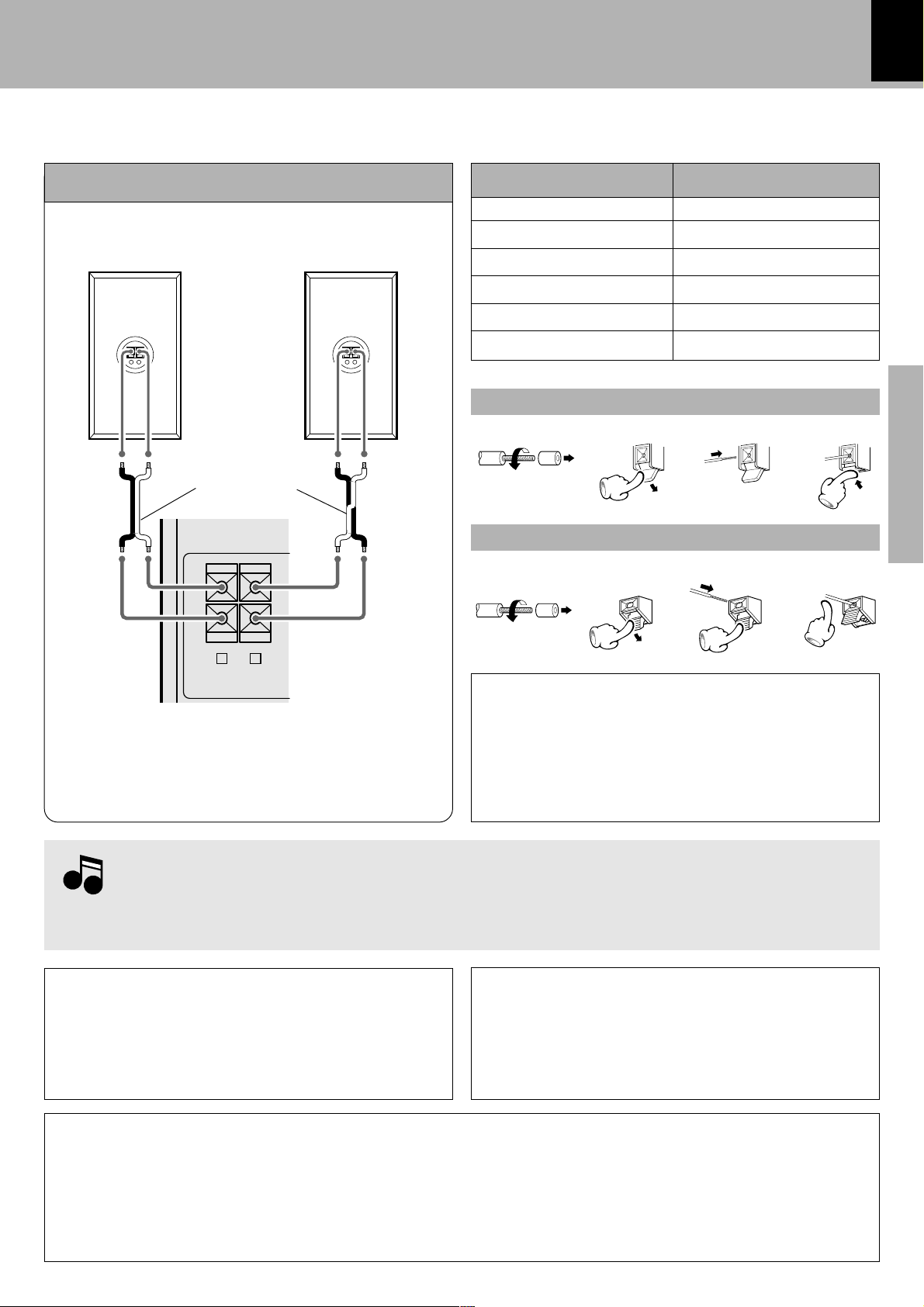
Connection of the system accessories
CAUTION
Connect the components as shown in the diagram. Only plug the power cord into a power outlet once connections are completed. The rear panel configuration is variable depending on the models (countries or area).
The accessory antenna is for temporary indoor use
only. For stable signal reception we recommend using an outdoor antenna. Remove the indoor antenna
if you connect one outdoors.
1 Connect to the antenna terminal.
2 Locate the position providing good recep-
tion condition.
3 Fix the antenna.
Note on Connection
FM indoor antenna AM loop antenna
The supplied antenna is for indoor use. Place it as far
as possible from the main system, TV set, speaker
cords and power cord, and set it to a direction which
provides the best reception.
ANTENNA
AM
ANTENNA
AM
FM
75Ω
GND
123
FM
75Ω
GND
Assemble.
System connection
Notes
7
Speakers
The speaker illustration is of the XD-653.
Speaker (left)Speaker (right)
−
+
·ª ·ª
Speaker cord
+
-
R L
FRONT
SPEAKERS
(
)
6-16Ω
÷ Never short-circuit the “+” and “–” speaker cords.
÷ If the left and right speaker connections or the “+” and
“–” polarity are inverted, the sound will be unnatural
with unclear positioning of musical instruments, etc. Be
sure to connect them properly.
−
+
Speaker Model NameSystem Name
XD-303
XD-353/XD-A33
XD-503
XD-553/XD-A53
XD-653
XD-753/XD-A73
LS-N303
LS-N353
LS-N503
LS-N553
LS-N653
LS-N753
Main Unit
1234
Twist
Speaker Unit (XD-653 only)
1234
Twist
CAUTION
(For U.S.A., U.S.-Military and Canada)
Be sure to adhere followings. Or proper ventilation will
be blocked causing damage or fire hazard.
÷ Do not place any objects impairing heat radiation onto
the top of unit.
Preparation section
1.Be sure to insert all connection cords securely. If their connections are imperfect, the sound may
Notes
Notes
not be produced or noise may interfere.
2.Before plugging or unplugging a connection cord, be sure to unplug the power cord from the wall
AC outlet. If connection cords are plugged or unplugged with the power cord left plugged in,
malfunction or damage may result.
Malfunction of microcomputer
If operation is not possible or erroneous display appears
even though all connections have been made properly,
Speaker and TV installation
The magnet in the speaker may cause color irregularity on
the TV. Place the speaker farther away from the TV set.
reset the microcomputer. Refer to “In case of difficulty”.
E
CAUTION
Be sure to adhere followings. Or proper ventilation will be blocked causing damage or fire hazard.
• Do not place any objects impairing heat radiation onto the top of unit.
• Leave a space around the unit (from the largest outside dimension including projection) equal or greater than, shown
below.
Top panel : 50 cm Side panel : 10 cm Back panel : 10 cm

8
Note
System connection
Connection with other components
CAUTION
Note on Connection
(optional or commercially-available equipment)
Connect the components as shown in the diagram. Only plug the power cord into a power outlet once connections are completed. The rear panel configuration is varies depending on the model (countries or area).
MD recorder, DVD player, VCR or analog turntable
DVD player/VCR/analog turn-
MD recorder
Digital
input
Preparation section
Optical-fiber cable
Audio
output
L
R
DVD/VIDEO INPUT
table (P-110/optional)
Audio output
DIGITAL OUT OPTICAL jack
Remove the cap and plug the optical-fiber cable.
Optical-fiber cable
(Provided with the MD
recorder)
÷ Insert the optical-fiber cable straight into the connector until it clicks.
÷ Be sure to attach the protection cap when the connector is not used.
÷ Never bend or bundle up the optical-fiber cable.
DIGITAL OUT
DIGITAL OUT
OPTICAL
For XD-753/653/XD-553/503
(Europe and U.K. only)
OPTICAL
Cap
Note
Note
When an external system component is connected, please read the instruction manual of the
component as well.
System connection
9
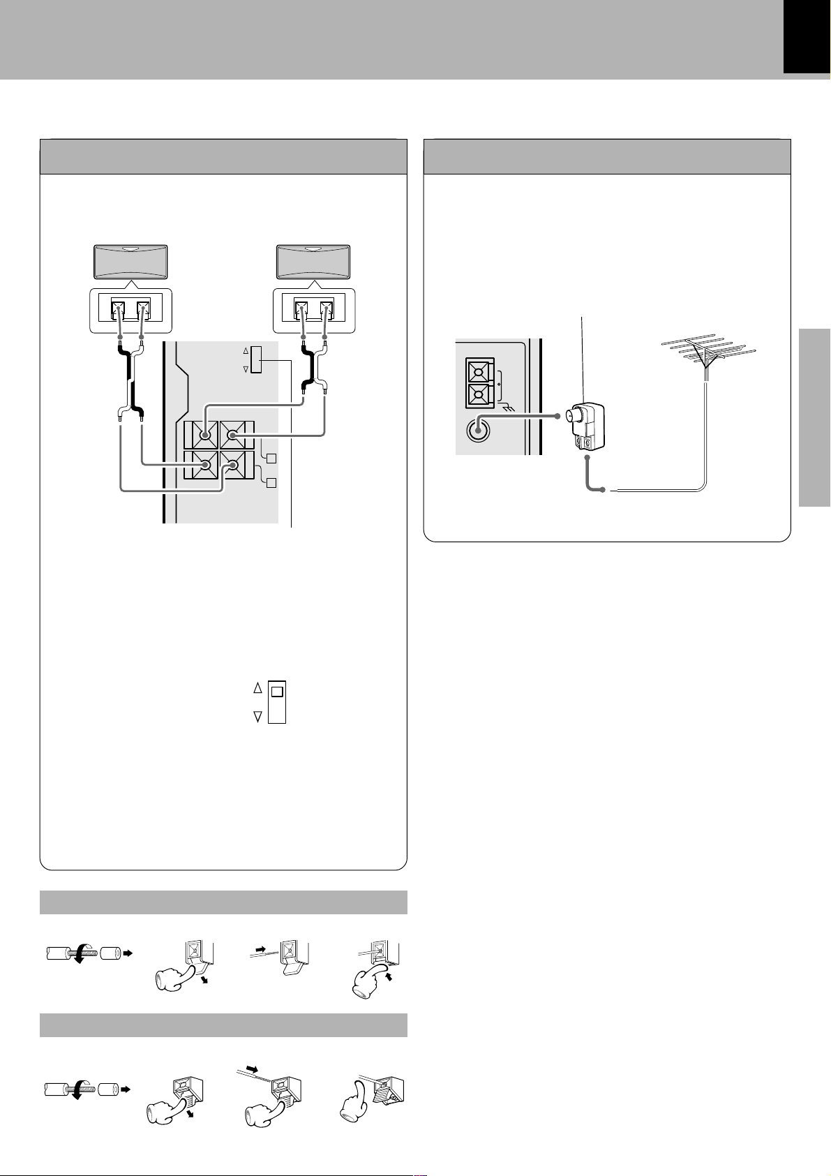
Surround (rear) speakers
Except for U.S.A. and Canada
Lead the 75Ω coaxial cable connected to the FM out-
FM outdoor antenna
door antenna into the room and connect it to the FM
75Ω terminal.
RL
Use a commercially-available antenna
−+−+
·ª · ª
SURROUND
ON
OFF
+
-
SURROUND
SPEAKERS
(
)
8-16Ω
L
R
Surround switch
ANTENNA
adapter (a small-sized model).
AM
GND
FM
75Ω
With regards to the SURROUND switch
This switch can be used only when the separately sold
surround (rear) speakers are connected. When the
switch is set to ON, surround playback can be enjoyed.
When this switch is set to OFF, normal playback is executed.
SURROUND
ON
OFF
Preparation section
÷ Please operate this switch while the power is switched
off.
÷ We recommend that this switch be set to OFF when no
surround (rear) speakers are connected to obtain a
better sound quality.
÷ When the switch is set to OFF, no sound will come from
the surround (rear) speakers.
Main Unit
123
Twist
4
Speaker Unit
1234
Twist

10
Controls and indicators
Main unit
™%$ ^&*( )¡#
1
2
3
4
Preparation section
5
6
7
8
9
0
!
@
STANDBY
DISPLAY/DEMO
SOUND
CONTROL
DECK
TIMER
MENU
O
N
C
I
T
T
L
U
M
SELECTBACK ENTER
PHONES
PUSH
OPEN
A
PLAY
I/
TUNING
MODE
R
O
L
VOLUME
CONTROL
E
X
.
B
A
S
S
DISC
1
DISC
2
DISC
3
DISC SKIP
OPEN/
CLOSE
REVERSE
REC/ARM
MODE TAPE EQ
PUSH
OPEN
DECK
B
REC/PLAY
£
¢
∞
§
¶
•
ª
º
⁄
CD player unit
# 7 (stop) key ¡
Operation key for the CD player and cassette deck.
( CD (6) key ¡
Press to select the CD and start playback.
™ Disc tray )
Three discs can be stored.
£ DISC SELECTOR keys ¡
The disc for playback (or recording) is selected.
¤
¢ DISC SKIP key ¡
The disc for playback (or recording) is selected.This is also
used for loading CDs onto the disc tray.
∞ 0 OPEN/CLOSE key )
The disc tray is opened and closed.

Receiver
Controls and indicators
11
1 STANDBY indicator *
The indicator lights up when the power is set to the
STANDBY mode.
2 STANDBY ( ) key *
STANDBY (POWER) key (For U.S.A. Canada)
*
Power ON/OFF switching is executed.
3TIMER indicator Q
The indicator lights up when the power is set to the
STANDBY mode after having activated a timer program.
4 DISPLAY/DEMO key 4y
Switches the displayed information.
5 TUNING MODE key
Switches the tuning mode.
6 SOUND CONTROL key y
Press to select the equalizer and 3D surround settings.
7 MENU key %
Press to switch the mode set with the MULTI CON-
TROL jog dial ON or OFF.
8 MULTI CONTROL jog dial %£§
Turn this dial to select optimum modes according to the
desired operations.
When the CD input is selected, this dial is used to skip
tracks.
When the TUNER input is selected, this dial is used to
select a station.
When the TAPE input is selected, this dial is used to fast
forward or backward (rewind) the tape..
9 SELECT key %
Used for setting of various modes or establishing a
selection.
0 BACK key %
Press when setting a mode using the MULTI CON-
TROL jog dial to return to the previous step and restart
the operation from there.
! ENTER key %
Used for entering a selected mode in memory or executing it.
@ PHONES jack *
For connection of a headphone (optional).
# 7 (stop) key ¡
Operation key for the CD player and cassette deck.
When power is STANDBY:
Used for displaying the time. (When this key is pressed
while the “TIMER” indicator is lit, the timer icon and the
timer reservation setting mode appears in the display,
then the display returns to the previous condition.)
$ AUX (DVD/VIDEO) key *
Press to select the source connected to the DVD/VIDEO
INPUT jacks.
% Display @
* TUNER (BAND) key §
Press to select the tuner and switch the receiving band.
) VOLUME CONTROL knob *
This is used for volume adjustment.
¡ EX. BASS (Extra bass) key (
Switches the extra bass play on and off.
Preparation section
Cassette deck unit
# 7 (stop) key £
Operation key for the CD player and cassette deck.
^ TAPE A (™ £) key ™
Press to select the deck A and start playback.
& TAPE B (™ £) key ™
Press to select the deck B and start playback.
§ TAPE EQ. key £
Press to switch the Tape Equalizer on and off.
¶ REC/ARM key ª
Press to start recording. Pressing this key while recording pauses creates a non-recording space (blank) of
about 4 seconds.
• REVERSE MODE key £ª
The reverse mode of the deck (both sides, repeated,
one side) is switched.
00
ª
0 PUSH OPEN key (B)
00
Press to load or remove a tape.
º B deck cassette holder
⁄ A deck cassette holder
00
¤
0 PUSH OPEN key (A)
00
Press to load or remove a tape.

12
Controls and indicators
Display
actually appears on the display.
REC
TOTAL
AUTO
RPT.DISC ST.
1
23
PTY
RANDOM ALL
PGM
6
Preparation section
1 Timer-related indicators
2 Sound level meter
The display varies according to the music or the operations of the CD, tape, etc.
During the volume adjustment, this meter displays the
current sound level as a reference.
3 Equalizer/3D surround/Ex. Bass indicators
4 Cassette deck-related indicators
This section contains the cassette deck operation indicators. The indicated information includes the tape
reverse mode and tape transport direction.
The displays given in this manual are approximations only. They may differ from what
3D
BASS
EQ
AB
••••••••••
578
5 Character information display
Displays the input selection, frequency, volume level,
etc.
6 Tuner-related indicators
7 REPEAT/PGM/RANDOM/TOTAL indicators
8 CD player-related indicators
This section contains the CD play and pause mode
indicators.
4321
T.EQ
MHz
kHz
Controls and indicators
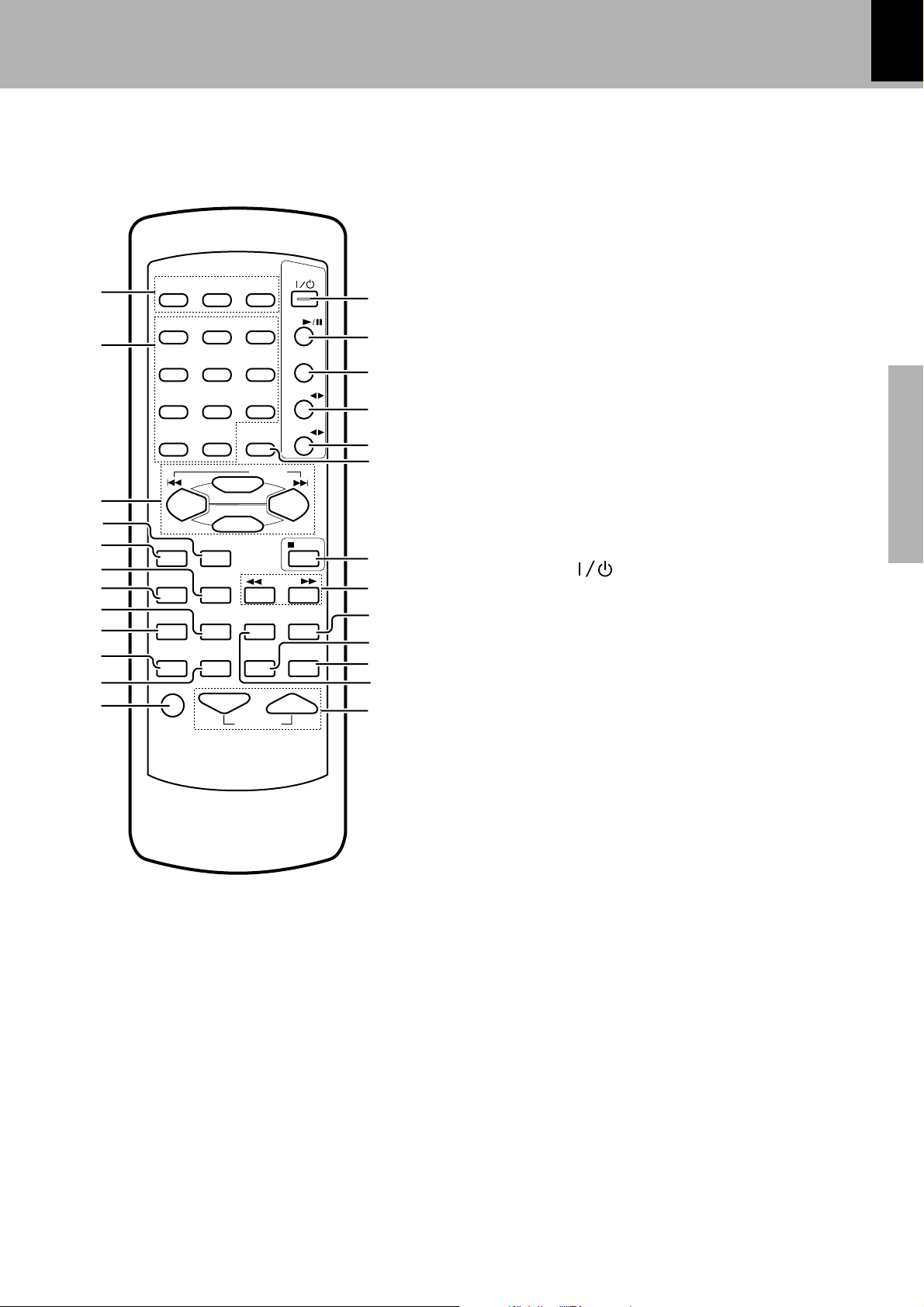
Remote control unit
The keys on the remote control unit with the same names as on the main unit have the same function as the keys
on the main unit.
4 BACK key %
5 ENTER key %
POWER
#
CD
$
TUNER/BAND
1
2
DISC 1 DISC 2 DISC 3
1
23
456
%
DISC
SKIP
P.CALL
TAPE A
^
TAPE B
&
*
3
789
0 +10
MENU
SELECT
4
5
6
7
8
TAPE EQ
REPEAT
BACK
REV.MODE
RANDOM
TIME
TUNING
PTY
STOP
RDS DISP
TEXT DISP
(
)
¡
ENTER
9
0
EX.BASS
SOUNDCONT
SLEEP
AUX
!
@
MUTE VOLUME
1 DISC SELECTOR keys ¡
The disc for playback (or recording) is selected.
2 Numeric keys ¡
Used as number keys when the input is CD or TUNER.
3 MULTI CONTROL keys %£§
The left and right keys have the same functions as the
MULTI CONTROL jog dial on the main unit.
P.CALL 4 ¢ (skip) keys (CD/TUNER)
When the CD input is selected, press to skip forward or
backward on the disc.
When the TUNER input is selected, press to select
preset station.
When the TAPE input is selected, press the key to fastforward or rewind the tape.
SELECT key %
MENU key %
™
£
¢
∞
¡¶
6 REV. MODE key £ª
The reverse mode of the deck (both sides, repeated,
one side) is selected.
7 TAPE EQ key £
8 RANDOM key fl
For CD playback, switching is executed between random playback and normal playback.
9 REPEAT key ›
Used for repeated playback of a CD.
0 AUX key *
Press to select the source connected to the DVD/VIDEO
INPUT jacks.
! EX. BASS key (
@ MUTE key (
This is used to mute the sound temporarily.
# POWER ( ) key *
Power ON/OFF switching is executed.
$ CD (6) key )
% TUNER/BAND key §
^ TAPE A (™ £) key ™
& TAPE B (™ £) key ™
* DISC SKIP key ¡
( 7 STOP key ¡£
Operation key for the CD player and cassette deck.
) TUNING (1 ¡) keys (CD/TAPE/TUNER)
¡£§
When the CD or TAPE input is selected, press to fast
forward or backward (rewind) the disc or tape.
When the TUNER input is selected, press to select a
station.
¡ TEXT DISP key ‚
Press to switch the text information recorded in a CD
TEXT disc.
RDS DISP key (For U.K. and Europe)
The display contents are switched during reception of
RDS broadcasts.
™ SOUND CONTROL key y
Press to select or the equalizer and 3D surround settings.
£ SLEEP key i
Press to set the sleep timer.
¢ TIME key ¡
Press to switch the time information on the CD player
unit.
PTY key (For U.K. and Europe) °
This is used to specify the program type when searching for a station.
∞ VOLUME keys *
This is used for volume adjustment.
13
Preparation section
‡

Operation of remote control unit
1
2
14
Loading batteries
1 Remove the cover. 3 Close the cover.
2 Insert batteries.
÷ Insert two R6 (“AA”-size) batteries
following the polarity indications.
Operation
Plug the power cord into the mains power outlet and
press the on/standby ( POWER) key of the remote
control unit to turn power ON. After the power has been
turned ON, press the desired key.
Preparation section
To turn power off, press the on/standby( POWER) key
again.
The power mode enters the STANDBY mode in which
the “STANDBY” indicator lights up. (The “TIMER” indicator also lights in this mode if a timer program has
been activated.)
÷ When pressing more than one remote control key suc-
cessively, press the keys securely by leaving an interval
of 1 second or more between the key presses.
Operating range
(approx.) Remote
6m
30
sensor
30
˚
˚
Notes
Notes
1.The provided batteries are intended for use in operation checking, and their service life may be short.
2.When the remote controllable distance becomes short, replace both of the batteries with new ones.
3.If direct sunlight or the light of a high- frequency fluorescent lamp (inverter type, etc.) is incident to the remote
sensor, malfunction may occur. In such a case, change the installation position to avoid malfunction.
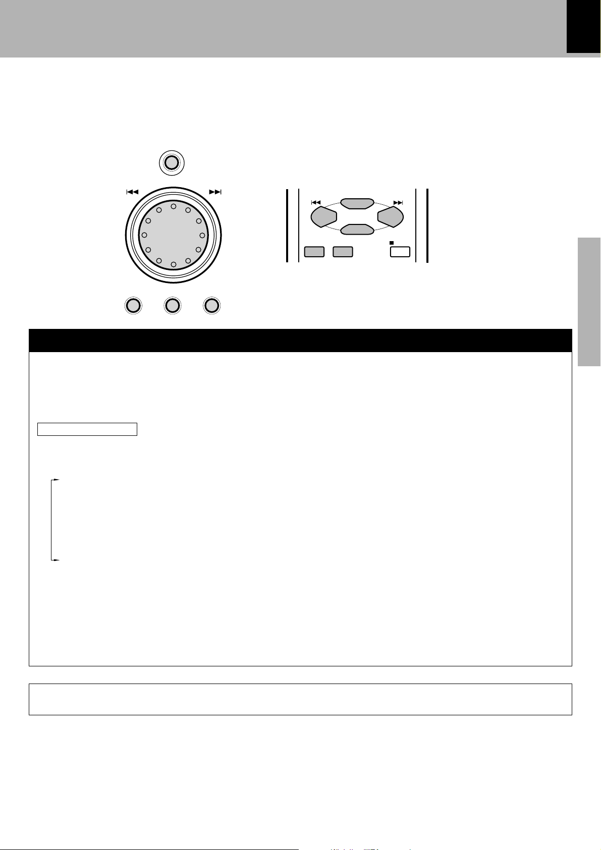
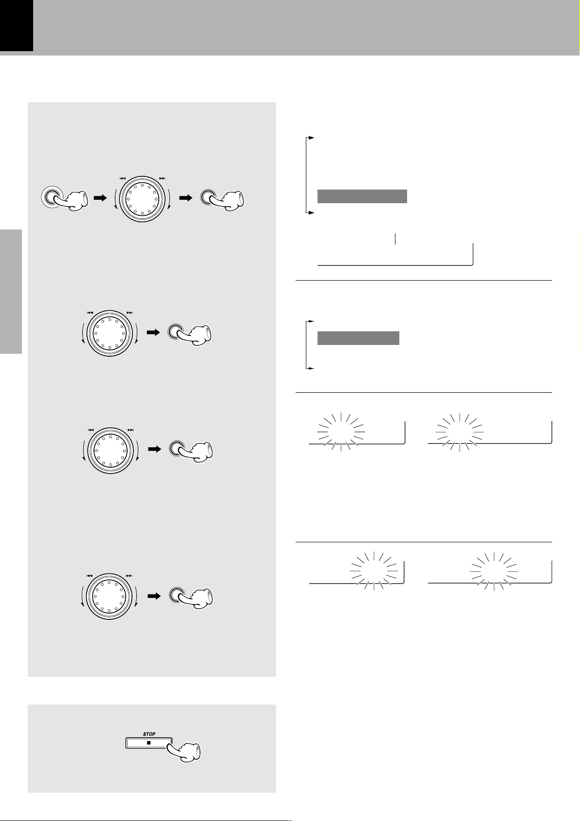
Operation of the jog dial
This unit has a jog dial named the MULTI CONTROL jog dial.
The MULTI CONTROL jog dial makes it possible to set (establish) many functions in a simple procedure.
When the MENU key is pressed, the items appears in the display according to the MULTI CONTROL jog dial
operation so you can select the desired mode based on a more intuitive method.
You can also use the 4/¢ keys on the remote control unit instead of the MULTI CONTROL jog dial.
MENU
O
N
C
I
T
T
L
U
M
SELECTBACK ENTER
R
O
L
ENTER
BACK
MENU
SELECT
P.CALL
STOP
15
Preparation section
MULTI CONTROL jog dial
1 Press the MENU key to enter the MULTI CONTROL setting mode.
2 Select an operation mode by turning the MULTI CONTROL jog dial (or pressing the MULTI CONTROL
keys on the remote control unit).
3 Set, establish or execute (determine) items by pressing the SELECT key and/or ENTER key.
Display examples
The following items can be selected by turning the MULTI CONTROL jog dial.
“CD Program Play”
“Recording Options”
“Tape Dubbing”
“Audio Options”
“Clock Options”
“Language Options”
÷ To cancel the mode for setting (using) MULTI CONTROL, read the description of each item in this manual.
÷ Press the BACK key to return to the previous step and restart operation from there. (The BACK key is inoperative once scrolling
message “Press ' ENTER ' to - - -” has been displayed.)
÷ With the remote control unit, pressing the MENU key makes it possible to select the same items as those available on the main
unit using the MULTI CONTROL keys.
In the MULTI CONTROL setting mode, only the volume control and 7 STOP key are operative.
16
m8:00a
m8:45a
Clock adjustment
This unit incorporates a clock function. Be sure to adjust to the correct time before using the timer
function. The time can be displayed only while the power is off.
The following items can be selected by turning the
Select “Clock Options”.
1
MULTI CONTROL jog dial.
“CD Program Play”
“Recording Options”
“Tape Dubbing”
“Audio Options”
MENU
O
N
C
I
T
T
R
L
O
U
L
M
SELECT
“Clock Options”
“Language Options”
+Scrolled display (Clock Options)
Cilock Opt
Select “Adjust Time”.
2
The following items can be selected by turning the
O
N
C
I
T
T
R
L
U
M
Preparation section
O
L
SELECT
MULTI CONTROL jog dial.
“Sleep Timer”
“Adjust Time”
“Timer Play”
“Auto Power Save”
Adjust the hour.
3
U
M
To decrease
the figure
Adjust the minute.
4
U
M
To decrease
the figure
O
N
C
I
T
T
R
L
O
L
To increase
the figure
O
N
C
I
T
T
R
L
O
L
To increase
the figure
SELECT
ENTER
Example: Adjustment to 8:45
08:0
(For U.K. and Europe)
0Ô1Ô2...13Ô14...Ô0 ...
÷ The time display starts to blink.
÷ Press the SELECT key. The hour is entered and the
minute display starts to blink.
(Other countries)
AM12ÔAM1ÔAM2...
PM1ÔPM2...ÔAM12 ...
58:4
(Other countries)(For U.K. and Europe)
00Ô01Ô02...59Ô00Ô01...
÷ Press the BACK key to return to the previous step and
restart operation from there.
÷ To adjust correct time, press the ENTER key at the same
moment as a time announcement.
To display the time
(In standby mode)
(Displayed for approx. 5 sec.)
÷ The clock display blinks after the power cord has been
unplugged from the AC power outlet and plugged in
again or after a power failure. In this case, set the time of
the day again.

Changing the display language
M
U
L
T
I
C
O
N
T
R
O
L
M
U
L
T
I
C
O
N
T
R
O
L
You can change the display language manually.
Select “Language Options”.
1
O
N
C
I
T
T
R
L
O
U
L
MENU
M
SELECT
17
The following items can be selected by turning the
MULTI CONTROL jog dial.
“CD Program Play”
“Recording Options”
“Tape Dubbing”
“Audio Options”
“Clock Options”
“Language Options”
+Scrolled display (Language Options)
LOanguage
Select the desired language.
2
The following items can be selected by turning the
O
N
C
I
T
T
R
L
O
U
L
M
ENTER
When you do not recognize which language is displayed:
÷ Press the MENU key and select “Language Options” (English), “Options de langue” (French),“Sprach-
Einstellungen” (German), “Opción Idioma” (Spanish) or “Opzioni lingua” (Italian), then select the desired
language.
About the beep sound
When you press the key, a beep sounds. The number
of times that the beep sounds changes depending on
the operation.
MULTI CONTROL jog dial.
“English”
“Français” (French)
“Deutsch” (German)
“Español” (Spanish)
“Italiano” (Italian)
“Language Options”
2 Select “Beep sound”.
SELECT
Preparation section
When a beep sounds
Once: Normal operation
twice: The MENU or ENTER key is pressed.
three times: Abnormal operation (The error message
appears in the display.)
no sound: The key that cannot be operated is
pressed.
You can also set the beep to OFF:
1 Select “Audio Options”.
O
N
C
I
T
T
R
L
O
U
L
MENU
M
SELECT
3 Select “Beep on” or “Beep off”.
SELECT
1 “Beep on”
2 “Beep off”
18
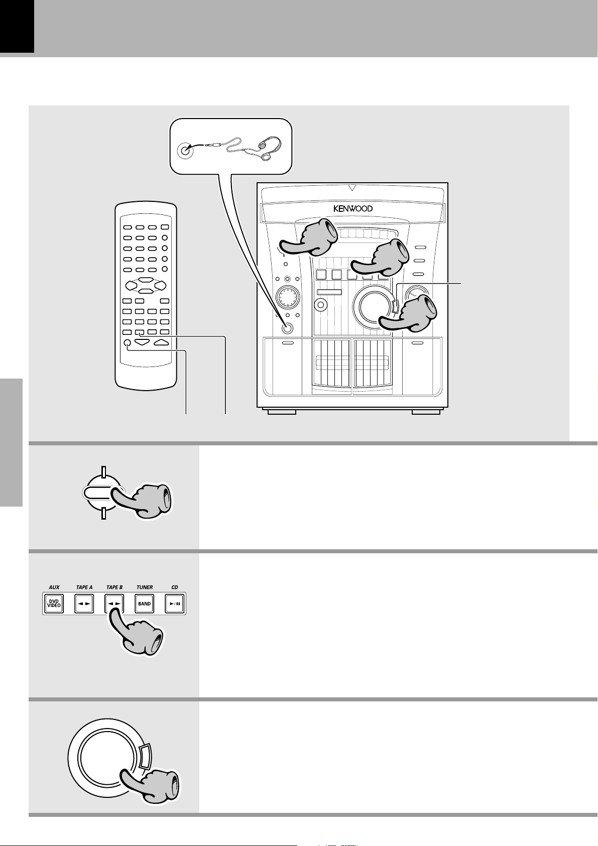
Let’s have sound
Basic operation
PHONES
Muting the sound temporarily
(MUTE)
Listening through headphones
Insert the headphone plug into the PHONES jack.
÷ The sounds from all speakers are cut off.
1
1
22
33
Reproducing sound with enhanced bass
(EX.BASS)
Reproducing sound
with enhanced bass
(EX.BASS)
Basic section
STANDBY
TIMER
11
22
VOLUME
CONTROL
E
X
.
B
A
S
S
1. Switching the power ON (OFF)
When the power is ON, pressing the STANDBY key enters the power
STANDBY mode, in which the standby indicator lights up.
2. Selecting the desired output
Select the desired source by pressing the AUX (DVD/VIDEO), TAPE A, TAPE
B, TUNER, or CD key.
÷ When you press the TAPE A, TAPE B, or CD key, the unit starts playback
automatically.
÷ If you select the AUX (DVD/VIDEO) (external input) mode, also read the
instruction manual of the component connected to the DVD/VIDEO INPUT
jacks.
3. Volume adjustment
÷ The display shows a reference value. (The reference value is also shown visually by
the sound level meter.)
33
 Loading...