


COMPACT HIFI SYSTEM
XD SERIES
XD-A31
XD-302
XD-352
XD-372S
INSTRUCTION MANUAL
KENWOOD CORPORATION
This instruction manual is used to describe multiple models listed above.
Model availability and features (functions) may differ depending on the country and sales area.
B60-4304-08 00 MA (K,M,T,X,Y) OC 99/01
2 Before applying power  Caution : Read this page carefully to ensure safe operation.
XD SERIES (En)
Units are designed for operation as follows.
U.S.A. and Canada ................................................. |
AC 120 V only |
Austraria ................................................................... |
AC 240 V only |
Preparation
Europe and U.K. ...................................................... |
AC 230 V only |
*Other countries ............... |
AC 110-120 /220-240 V switchable |
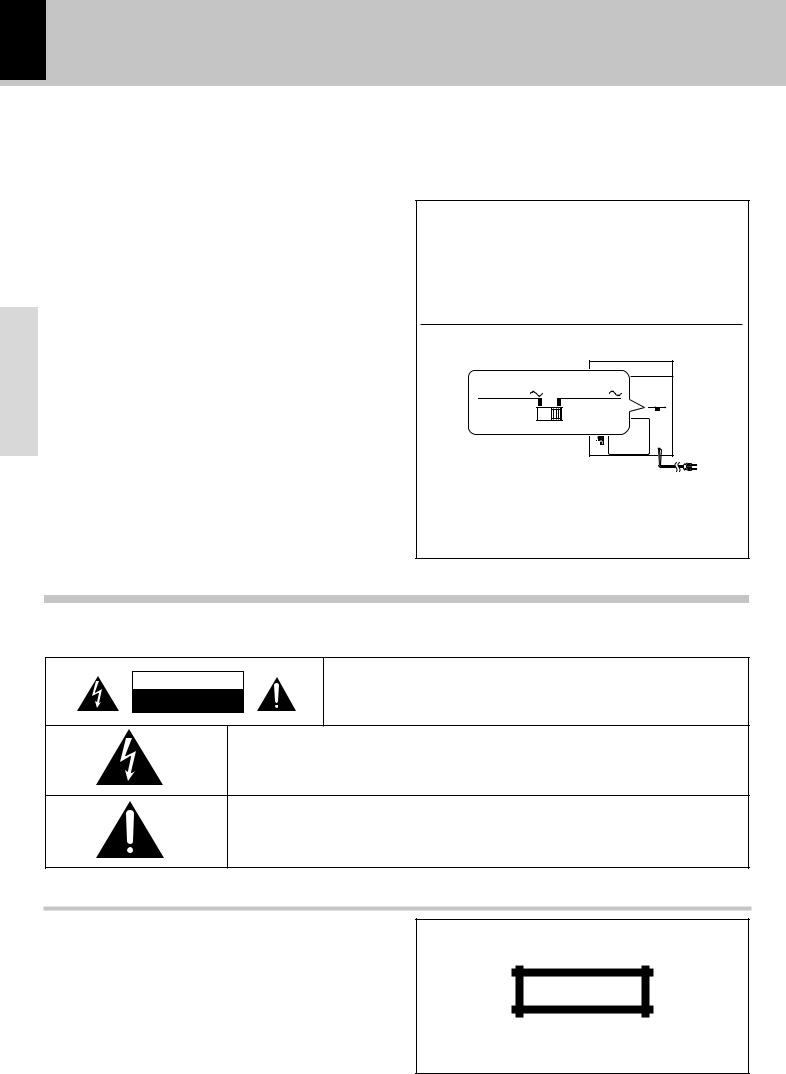
AC voltage selection
This unit operates on 110-120 or 220-240 volts AC . The AC voltage selector switch on the rear panel is set to the voltage that prevails in the area to which the unit is shipped. Before connecting the power cord to your AC outlet, make sure that the setting position of this switch matches your line voltage. If not, it must be set to your voltage in accordance with the following direction.
AC voltage selector switch
AC 110 –120V |
AC 220 –240V |
Move switch lever to match your line voltage with a small screwdriver or other pointed tool.
Note:
Our warranty does not cover damage caused by excessive line voltage due to improper setting of the AC voltage selector switch.
Safety precautions
WARNING : TO PREVENT FIRE OR ELECTRIC SHOCK, DO NOT EXPOSE THIS APPLIANCE TO RAIN OR MOISTURE.
CAUTION
RISK OF ELECTRIC SHOCK
DO NOT OPEN
CAUTION: TO REDUCE THE RISK OF ELECTRIC SHOCK, DO NOT REMOVE COVER (OR BACK). NO USER-SERVICEABLE PARTS INSIDE, REFER SERVICING TO QUALIFIED SERVICE PERSONNEL.
THE LIGHTNING FLASH WITH ARROWHEAD SYMBOL, WITHIN AN EQUILATERAL TRIANGLE, IS INTENDED TO ALERT THE USER TO THE PRESENCE OF UNINSULATED “DANGEROUS VOLTAGE” WITHIN THE PRODUCT’S ENCLOSURE THAT MAY BE OF SUFFICIENT MAGNITUDE TO CONSTITUTE A RISK OF ELECTRIC SHOCK TO PERSONS.
THE EXCLAMATION POINT WITHIN AN EQUILATERAL TRIANGLE IS INTENDED TO ALERT THE USER TO THE PRESENCE OF IMPORTANT OPERATING AND MAINTENANCE (SERVICING) INSTRUCTIONS IN THE LITERATURE ACCOMPANYING THE APPLIANCE.
The marking of products using lasers (Except for some areas)
CLASS 1
LASER PRODUCT
The marking is located on the rear panel and says that the component uses laser beams that have been classified as Class 1. It means that the unit is utilizing laser beams that are of a weaker class. There is no danger of hazardous radiation outside the unit.
Caution : Read the pages marked  carefully to ensure safe operation. 3
XD SERIES (En)
Contents |
|
Preparation |
|
Before applying power ......................................................... |
2 |
Safety precautions .................................................................................. |
2 |
Contents ............................................................................................................ |
3 |
CHANNEL SPACE setting ............................................................................... |
3 |
Special features .............................................................................................. |
4 |
Demonstration ................................................................................................. |
4 |
Accessories ..................................................................................................... |
4 |
IMPORTANT SAFEGUARDS .................................................. |
5 |
Handling of discs and tapes ...................................................... |
7 |
system connection ....................................................................... |
8 |
AM loop antenna connection ....................................................................... |
8 |
FM antenna connection ................................................................................. |
8 |
Connection of the speaker system ............................................................. |
9 |
Connection of options (Optional parts) ....................................................... |
9 |
Controls and indicators ............................................................. |
10 |
CD and Receiver unit .................................................................................... |
10 |
Cassette deck unit ........................................................................................ |
11 |
Display ............................................................................................................ |
11 |
Operation of remote control unit ............................................. |
12 |
Clock adjustment .......................................................................................... |
13 |
Operation |
|
Let's put out some sound .......................................................... |
14 |
Basic use method ......................................................................................... |
14 |
Muting the sound temporarily .................................................................... |
15 |
Listening through headphones ................................................................... |
15 |
Changing the Tone (Selecting the equalizer pattern ) ........................... |
15 |
Changing the Tone (Selecting the bass boost ) ....................................... |
15 |
Playback of CDs ......................................................................... |
16 |
Sequential playback from the first track .................................................. |
16 |
Playback from the desired track ................................................................ |
17 |
Listening in the desired sequence (program playback) ........................ |
18 |
Repeat Playback ........................................................................................... |
20 |
Random Playback ......................................................................................... |
21 |
Receiving broadcast station .................................................... |
22 |
Collective presetting of stations (auto preset) ........................................ |
23 |
One-by-one presetting (manual preset) .................................................... |
23 |
Playback of tapes....................................................................... |
24 |
Recording (Deck B only) ........................................................... |
26 |
Copying tape (Tape dubbing) ...................................................................... |
28 |
Convenient CD recording ......................................................... |
29 |
Recording only desired titles (CD ONE TRACK RECORDING) ............... |
30 |
Recording of an entire CD (CD DIRECT RECORDING) ............................. |
31 |
Recording the programmed titles (CD PROGRAM RECORDING) ....... |
32 |
Timer operation .......................................................................... |
34 |
Sleep timer (SLEEP) ...................................................................................... |
34 |
Timer programming ...................................................................................... |
35 |
Knowledge |
|
Important Items........................................................................... |
38 |
In case of difficulty .................................................................... |
39 |
Specifications............................................................................. |
42 |
Preparation
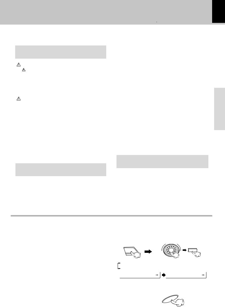
CHANNEL SPACE setting
(Except for the U.S.A., Canada, U.K. Europe and Australia)
The space between radio channels has been set to the one that prevails in the area to which the system is shipped. However, if the current channel space setting does not match the setting in the area where the system is to be used, for instance when you move from area 1 or area 2 shown in the following table or vice versa, proper reception of AM/FM (SW/MW/FM) broadcasts cannot be expected. In this case, change the channel space setting in accordance with your area by referring to the following table.
1 Select the TUNER input.
2While holding the SELECT key depressed, turn the SOUND CONTROL jog dial to select the system mode.
INPUT |
SELECT |
|
Area |
CHANNEL |
||
|
SPACE freq. |
|||
|
|
|||
|
|
|
||
1 |
USA, Canada and South |
FM : 100 kHz |
||
American countries |
AM : |
10 kHz |
||
|
||||
2 |
Other countries |
FM : |
50 kHz |
|
AM : |
9 kHz |
|||
|
|
|||
1 |
“FM100/AM10 kHz” |
STEP, |
2 |
“FM 50 /AM 9 kHz” |
STEP, |
F M 1 0 0 / A M 1 0 |
F M 5 0 / A M 9 |
|
÷The “AM” display is variable depending on the model (country or area), and “MW” may be displayed in some areas.
3 Establish the selection.
ENTER
4
XD SERIES (En)
Special features
3-Disc carousel CD player
Three discs can be set. There are various ways for enjoyment at the time of program play back, repeat playback, random playback, etc.
Double cassette deck
Two tape decks are installed, permitting dubbing from tape to tape and relay playback.
Simplified operations using large-sized Jog Dial
Preparation
This dial allows you to set the CD program and timer-related operations while observing the operating conditions shown by the display and icons.
3D large-sized color display panel
The large sound level meter represents the movement in music with brilliant colors to offer the joy of viewing the music at the same time as listening.
Convenient Timer Functions
An ON/OFF timer for listening at the same time each day and a sleep timer are provided.
Demonstration
When the power supply is restored after a power failure or the power cord is unplugged and plugged in again during use, this unit automatically starts the demonstration function (display only), During the demonstration, the display changes in sequence but the audio does not change. The demonstration can be canceled with the following procedure.
To switch over the demonstration :
DEMO |
Turn the unit OFF (STANDBY mode) and press the |
|||
key. |
|
|||
DISPLAY |
Each press of the key switches the demonstra- |
|||
|
||||
|
tion as shown below. |
|||
|
|
1 |
”Demo on“ (Demonstration executed) |
|
|
|
|||
|
|
|
2 |
“Demo off” (Demonstration canceled) |
|
|
|
||
÷ The setting is remembered even when the power is switched off.
Unpacking
Unpack the unit carefully and make sure that all accessories are put aside so they will not be lost.
Examine the unit for any possibility of shipping damage. If your unit is damaged or fails to operate, notify your dealer immediately. If your unit was shipped to you directly, notify the shipping company without delay. Only the consignee (the person or company receiving the unit) can file a claim against the carrier for shipping damage.
We recommend that you retain the original carton and packing materials for use should you transport or ship the unit in the future.
Keep this manual handy for future reference.
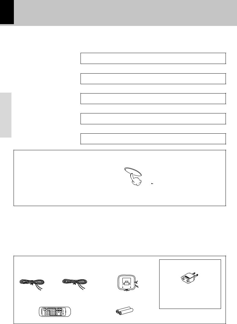
Accessories
FM indoor antenna (1) |
AM loop antenna (1) |
|||||||||
Europe and U.K. |
Other countries |
|
|
|
|
|
|
|
|
|
|
|
|
|
|
|
|
|
|
|
|
|
|
|
|
|
|
|
|
|
|
|
|
|
|
|
|
|
|
|
|
|
|
|
|
|
|
|
|
|
|
|
|
|
|
|
|
|
|
|
|
|
|
|
|
|
|
|
|
|
|
|
|
|
|
|
|
|
|
|
|
|
|
|
|
|
|
|
|
|
|
|
|
|
|
|
|
|
Remote control unit (1) |
Batteries (R6/AA) (2) |
AC plug adaptor (1)
Use to adapt the plug on the power cord to the shape of the wall outlet. (Accessory only for regions where use is necessary.)
MULTI CONTROL
IMPORTANT SAFEGUARDS
Please read all of the safety and operating instructions before operating this appliance. Adhere to all warnings on the appliance and in the instruction manual. Follow all the safety and operating instructions. These safety and operating instructions should be retained for future reference.
1.Power sources – The appliance should be connected to a power supply only of the type described in the instruction manual or as marked on the appliance. If you are not sure of the type of power supply to your home, consult your appliance dealer or local power company. For appliances intended to operate from battery power, or other sources, refer to the instruction manual.
2.Power-cord protection – Power-supply cords should be routed so that they are not likely to be walked on or pinched by items placed upon or against them, pay particular attention to cords at plugs, convenience receptacles, and the point where they exit from the appliance.
Never pull or stretch the cord.
3.CAUTION – Polarization – This appliance may be equipped with a polarized alternating-current line plug (a plug having one blade wider than the other). This plug will fit into the power outlet only one way. This is a safety feature. If you are unable to insert the plug fully into the outlet, try reversing the plug. If the plug should still fail to fit, contact your electrician to replace your obsolete outlet. Do not defeat the safety purpose of the polarized plug.
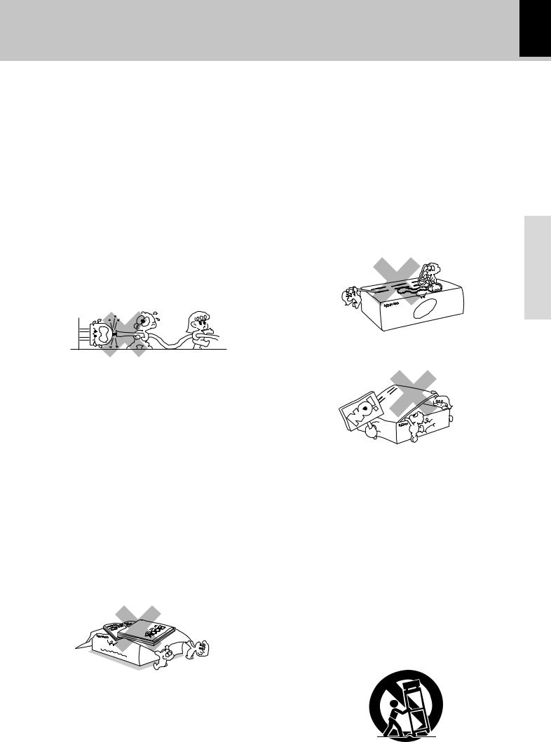
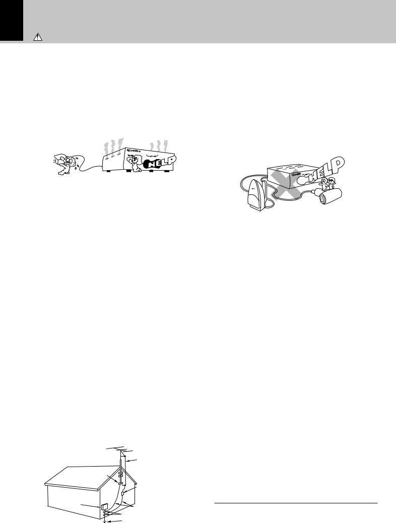
4.Ventilation – Slots and openings in the cabinet are provided for ventilation and to ensure reliable operation of the appliance and to protect it from overheating, and these openings must not be blocked or covered. The appliance should be situated so that its location or position does not interfere with its proper ventilation.
To maintain good ventilation, do not put records or a tablecloth on the appliance. Place the appliance at least 10 cm away from the walls.
Do not use the appliance on a bed, sofa, rug or similar surface that may block the ventilation openings. This appliance should not be placed in a built-in installation such as a bookcase or rack unless proper ventilation is provided or the manufacturer’s instructions have been adhered to.
5.Water and moisture – The appliance should not be used near water - for example, near a bathtub, washbowl, kitchen sink, laundry tub, in a wet basement, or near a swimming pool, etc.
 Caution : Read this page carefully to ensure 5 safe operation.
XD SERIES (En)
6. Temperature – The appliance may not function |
|
|
properly if used at extremely low, or freezing |
|
|
temperatures. The ideal ambient temperature is |
|
|
above +5°C (41°F). |
|
|
7. Heat – The appliance should be situated away from |
|
|
heat sources such as radiators, heat registers, stoves, |
|
|
or other appliances (including amplifiers) that produce |
|
|
heat. |
|
|
8. Electric shock – Care should be taken so that objects |
|
|
do not fall and liquid is not spilled into the enclosure |
|
|
through openings. If a metal objects, such as a hair |
|
|
pin or a needle, comes into contact with the inside of |
|
|
this appliance, a dangerous electric shock may result. |
|
|
For families with children, never permit children to |
Preparation |
|
put anything, especially metal, inside this appliance. |
||
|
9.Enclosure removal – Never remove the enclosure. If the internal parts are touched accidentally, a serious electric shock might occur.
10.Magnetic fields – Keep the appliance away from sources of magnetic fields such as TV sets, speaker systems, radios, motorized toys or magnetized objects.
11.Cleaning – Unplug this appliance from the wall outlet before cleaning. Do not use volatile solvents such as alcohol, paint thinner, gasoline, or benzine, etc. to clean the cabinet. Use a clean dry cloth.
12.Accessories – Do not place this appliance on an unstable cart, stand, tripod, bracket, or table. The appliance may fall, causing serious injury to a child or adult, and serious damage to the appliance. Use only with a cart, stand, tripod, bracket, or table recommended by the manufacturer, or sold with the appliance. Any mounting of the appliance should follow the manufacturer’s instructions, and should use a mounting accessory recommended by the manufacturer. An appliance and cart combination should be moved with care. Quick stops, excessive force, and uneven surfaces may cause the appliance and cart combination to overturn.
6 |
Caution : Read this page carefully to ensure safe operation. |
|
XD SERIES (En)
13.Lightning – For added protection for this appliance during a lightning storm, or when it is left unattended and unused for long periods of time, unplug it from the wall outlet and disconnect the antenna or cable system. This will prevent damage to the appliance due to lightning and power-line surges.
14.Abnormal smell – If an abnormal smell or smoke is detected, immediately turn the power OFF and unplug the appliance from the wall outlet. Contact your dealer or nearest service center.
|
|
|
|
|
|
|
|
Preparation |
|
|
|
|
|
|
|
|
|
|
|
|
|
|
|
|
15.Damage requiring service – The appliance should |
||||||
|
|
||||||
|
|
be serviced by qualified service personnel when: |
|||||
|
|
A. The power-supply cord or the plug has been |
|||||
|
|
damaged. |
|
|
|
||
|
|
B. Objects have fallen, or liquid has been spilled into |
|||||
|
|
the appliance. |
|
|
|
||
|
|
C. The appliance has been exposed to rain or water. |
|||||
|
|||||||
|
|
D. The appliance does not appear to operate normally |
|||||
|
|
by following the instruction manual. Adjust only those |
|||||
|
|
controls that are covered by the instruction manual as an |
|||||
|
|
improper adjustment of other controls may result in damage |
|||||
|
|
and will often require extensive work by a qualified |
|||||
|
|
technician to restore the appliance to its normal operation. |
|||||
|
|
E. The appliance has been dropped, or the enclosure |
|||||
|
|
damaged. |
|
|
|
||
|
|
F. The appliance exhibits a marked change in performance. |
|||||
|
|
16.Servicing – The user should not attempt to service |
|||||
|
|
the appliance beyond that described in the instruction |
|||||
|
|
manual. All other servicing should be referred to |
|||||
|
|
qualified service personnel. |
|
|
|
||
|
|
17.Outdoor antenna grounding – If an outside antenna |
|||||
|
|
is connected to the appliance, be sure the antenna |
|||||
|
|
system is grounded so as to provide some protection |
|||||
|
|
against voltage surges and built up static charges. |
|||||
|
|
Article 810 of the National Electrical Code |
ANSI/ |
||||
|
|
NFPA 70, provides information with respect to proper |
|||||
|
|
grounding of the mast and supporting structure, |
|||||
|
|
grounding of the lead-in wire to an antenna discharge |
|||||
|
|
unit, size of grounding conductors, location of antenna |
|||||
|
|
discharge unit, connection to grounding electrodes, |
|||||
|
|
and requirements for the grounding electrode. See |
|||||
|
|
Figure. |
|
|
|
||
|
|
|
|
|
|
||
|
|
|
EXAMPLE OF ANTENNA GROUNDING AS PER |
|
|
||
|
|
|
NATIONAL ELECTRICAL CODE |
|
|
||
|
|
|
|
|
ANTENNA |
|
|
|
|
|
|
|
LEAD IN WIRE |
|
|
|
|
|
GROUND |
|
|
|
|
|
|
|
CLAMPS |
|
|
|
|
|
|
|
|
|
ANTENNA |
|
|
|
|
|
|
|
DISCHARGE UNIT |
||
|
|
|
|
|
(NEC SECTION 810-20) |
||
|
|
|
ELECTRIC |
|
|
|
|
|
|
|
SERVICE |
GROUNDING CONDUCTORS |
|||
|
|
|
EQUIPMENT |
||||
|
|
|
|
|
(NEC SECTION 810-21) |
||
|
|
|
|
|
GROUND CLAMP |
|
|
|
|
|
|
|
POWER SERVICE GROUNDING |
||
|
|
|
|
|
ELECTRODE SYSTEM |
|
|
|
|
|
|
|
(NEC ART 250, PART H) |
|
|
|
|
NEC – NATIONAL ELECTRICAL CODE |
|
|
|
||
|
|
|
|
|
|
|
|
18.Power lines – An outside antenna system should not be located in the vicinity of overhead power lines or other electric light or power circuits, or where it can fall into such power lines or circuits. When installing an outside antenna system, extreme care should be taken to keep from touching such power lines or circuits as contact with them might be fatal.
19.AC outlets – Do not connect other audio equipment with a power consumption larger than that specified to the AC outlet on the rear panel. Never connect other electrical appliances, such as an iron or toaster, to it to prevent fire or electric shock.
20.Overloading – Do not overload wall outlets, extension cords, or integral convenience receptacles as this can result in a risk of fire or electric shock.
21.Attachment – Do not use attachments not recommended by the appliance manufacturer as they may cause hazards.
22.Replacementparts–Whenreplacementpartsarerequired, be sure the service technician has used replacement parts specified by the manufacturer or have the same characteristics as the original parts. Unauthorized substitutions may result in fire, electric shock, or other hazards.
23.Safety check – Upon completion of any service or repairs to this appliance, ask the service technician to perform safety checks to determine that the appliance is in proper operating condition.
Notes:
1.Item 3 is not required except for grounded or polarized equipment.
2.Item 17 and 18 are not required except for units provided with antenna terminals.
3.Item 17 complies with UL in the U.S.A.
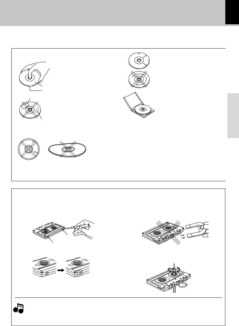
Handling of discs and tapes
Disc handling precautions
Label side
Playing
side
Sticker
Sticky paste
Handling
Hold compact discs so that you do not touch the playing surface.
÷Do not attach paper or tape to either the playing side or the label side of compact discs.
÷The paste left on the label surface after a sticker has been peeled off is a factor which may cause malfunction. If the surface is sticky due to remaining paste, be sure to clean it with alcohole before use.
Caution on disc used
Discs which can be played with this unit
Notes on cassette tape
Safety tab (accidental erasure prevention tab) After an important recording has been finished, break the safety tab, to prevent the recorded contents from being erased or recorded on accidentally.
For A side
For B side
To re-record |
Apply tape only to the position |
|
where the tab has been removed. |
1. Longer tape than 110 minutes cassette tape
Since longer tape than 110 minutes cassette tape is
Note very thin, the tape could adhere to the pinch roller or be easily cut. It is recommended that these tapes not be used with this unit to prevent possible damage.
7
XD SERIES (En)
|
|
|
Cleaning |
|
|
|
|
|
|
|
|
|
|
|
|
|
|
If fingerprints or foreign matter become |
|
|
|
|
attached to the disc, lightly wipe the |
|
|
|
|
disc with a soft cotton cloth (or similar) |
|
|
|
|
from the center of the disc outwards, |
|
|
|
|
in a radial manner. |
|
|
|
|
Storage |
|
|
|
|
When a disc is not to be played for a |
Preparation |
|
|
|
long period of time, remove it from the |
|
|
|
|
|
|
|
|
|
CD player and store it in its case. |
|
Never play a cracked or warped disc. |
|
|||
During playback, the disc rotates at high speed in the player. |
|
|||
Therefore, to avoid danger, never use a cracked or deformed disc or a |
|
|||
disc repaired with tape or adhesive agent. |
|
|||
Do not use cleaning discs. |
|
|||
Please do not use commercially available cleaning discs, they may dam- |
|
|||
age the internal mechanism. |
|
|||
CD (12 cm, 8 cm) |
|
|||
÷With CD-G (CD Graphics) discs, this unit can play only the audio. |
|
|||
To store cassette tapes |
|
|||
|
||||
Do not store the tapes in a place which is subject to direct |
|
|||
sunlight, or near equipment that generates heat. Keep the |
|
|||
cassette tapes away from any magnetic field. |
|
|||
N
S
When there is slack in the tape
In such a case, insert a pencil into the reel hole and wind the reel hub to remove the slack.
2.Endless tapes
Do not use an endless tape, as this could damage the mechanism of the unit.

8 system connection
XD SERIES (En)
1 |
2 |
3 |
Caution regarding placement |
To maintain proper ventilation, be sure to leave a space around the unit (from the largest outer dimensions including projections) equal to, or greater than, shown below.
Rear panel: 10 cm
AM loop antenna connection
Preparation
AM loop antenna connection
The supplied antenna is for indoor use. Place it as far as possible from the main system, TV set, speaker cords and power cord, and set it to a direction which provides the best reception.
FM antenna connection
ANTENNA
FM 75 Ω |
AM |
|
GND |
ANTENNA |
|
FM 75 Ω |
AM |
GND |
|
SUPER |
ANTENNA |
WOOFER |
|
PRE OUT |
|
|
|
FM 75 Ω |
AM |
|
AUX INPUT |
|
|
|
|
R |
L |
GND |
AC 110 –120V |
AC 220 –240V |
SPEAKERS |
|
|
|
|
(6–16 |
Ω) |
|
|
|
+
L
–
–
R
+
FM indoor antenna connection |
1 Strip the coating from the tip of cord |
The accessory antenna is for |
and twist the conductor. (Except for |
temporary indoor use only. |
Europe and U.K.) |
For stable signal reception |
2 Connect to the antenna terminal. |
we recommend using an |
3 Locate the position providing good |
outdoor antenna. Remove |
reception condition. |
the indoor antenna if you |
4 Fix the antenna. |
connect one outdoors. |
|
ANTENNA |
|
FM 75 Ω |
AM |
GND |
|
FM outdoor antenna
Lead the 75Ω coaxial cable connected to the FM outdoor antenna into the room and connect it to the FM 75Ω termimal.
Antenna adapter (optional)
10mm 10mm
ANTENNA |
|
FM 75 Ω |
AM |
GND |
|
ANTENNA |
|
FM 75 Ω |
AM |
GND |
|
ANTENNA |
|
FM 75 Ω |
AM |
GND |
|
ANTENNA |
|
|
FM 75 Ω |
AM |
|
GND |
AC 110 –120V |
AC 220 –240V |
AUX
INPUT
R L
SPEAKERS (6–16 Ω)
+
L
–
–
R
+
ANTENNA |
|
|
FM 75 Ω |
AM |
|
GND |
AC 110 –120V |
AC 220 –240V |
AUX
INPUT
R L
SPEAKERS (6–16 Ω)
+
L
–
–
R
+
system connection 9
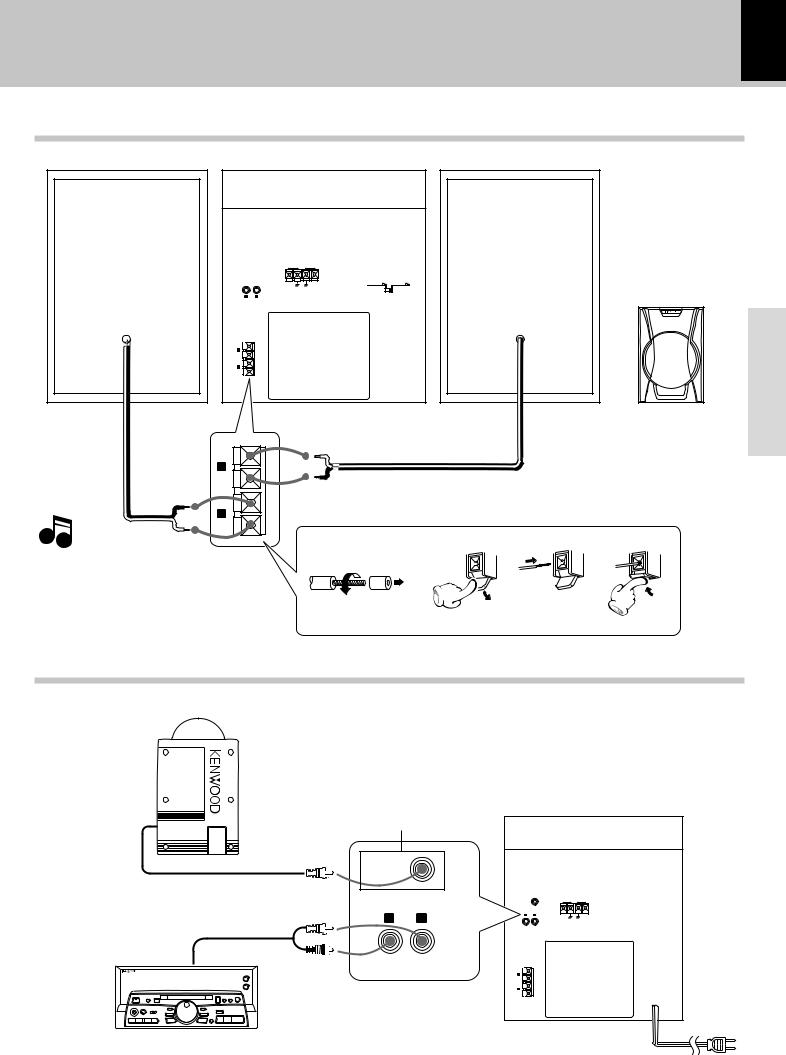
Connection of the speaker system
XD SERIES (En)
Do not plug the power cord into the power outlet until all of the required connections have been made.
ANTENNA |
|
|
FM 75 Ω |
AM |
|
GND |
AC 110 –120V |
AC 220 –240V |
AUX
INPUT
R L
SPEAKERS (6–16 Ω)
+
L
–
–
R
+
Speaker front view (the front net can not be removed)
+ |
|
L |
Connect only provided main unit. |
– |
–
R
+
Note
• Never short-circuit the + and – speaker cords.
• If the left and right speakers are connected inversely or if the speaker cords are connected with reversed polarity, the sound becomes unnatural with ambiguous acoustic image positioning. Be sure to connect the speakers and speaker cords correctly.
Connection of options (Optional parts)
Connect separately sold parts as shown in the figure.
Do not plug the power cord into the power outlet until all of the required connections have been made.
SUPER WOOFER
Only XD-A31/XD-302
SUPER
WOOFER
PRE OUT
|
|
|
|
ANTENNA |
|
|
|
SUPER |
|
FM 75 Ω |
AM |
AUX INPUT |
WOOFER |
|
|||
PRE OUT |
|
|
|
||
|
|
|
|
||
R |
L |
AUX INPUT |
|
|
|
R |
L |
GND |
|
||
|
|
|
|
||
MD PLAYER Audio output |
SPEAKERS |
|
(6–16 |
Ω) |
|
|
|
|
+
L
–
–
R
+
Preparation
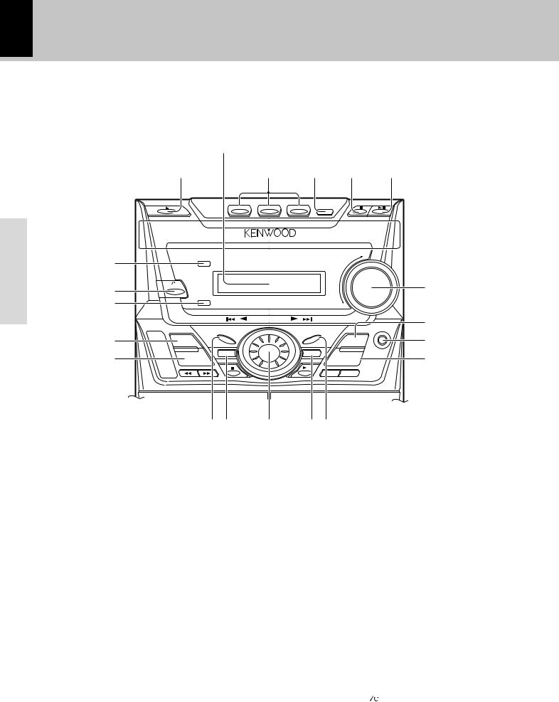
10 Controls and indicators
XD SERIES (En)
CD and Receiver unit
Preparation
Display
1 2 3 4 5
DISC 1 |
DISC 2 |
DISC 3 |
DISC SKIP |
( |
|
|
|
|
VOLUME |
|
|
|
|
|
|
|
|
* |
ON/STANDBY |
|
|
|
|
6 |
|
|
|
|
|
|
|
& |
|
|
|
|
|
|
|
|
|
MULTI CONTROL |
|
|
7 |
|
|
|
|
|
|
PHONES |
^ |
|
DEMO |
|
|
|
8 |
INPUT |
DISPLAY |
|
ENTER |
BAND |
||
% |
|
MENU |
|
SELECT |
|
9 |
EX.BASS |
|
|
|
TUNING MODE |
||
|
|
|
|
TAPE A/B REC/ARM |
|
|
|
|
$ # |
@ |
! 0 |
|
|
@MULTI CONTROL jog dial *
Turn this dial to select optimum modes according to the desired operations.
When the CD input is selected, this dial is used to skip tracks. When the TUNER input is selected, this dial is used to select
a station. |
|
#MENU key |
* |
Press to switch the mode set with the MULTI CONTROL jog dial ON or OFF.
$ DISPLAY/DEMO key |
4% |
Switches the display contents. |
|
*Used for demonstration (DEMO) ON/OFF. |
|
%EX. BASS (Extra bass) key |
% |
Switches the extra bass play on and off. |
|
^INPUT key |
$ |
Key for input switching. |
|
&TIMER indicator |
|
Lights up when the timer is set. |
|
*ON/STANDBY ( ) key |
$ |
ON/STANDBY (POWER) key (For U.S.A. Canada)
Power ON/OFF switching is executed.
(STANDBY indicator
Controls and indicators 11
XD SERIES (En)
Cassette deck unit |
1 |
2 |
3 4 5 |
|
|
TAPE A/B REC/ARM |
6 |
7 |
APLAY |
REC/ |
PLAYB |
Preparation
1Fast forward and rewind (1, ¡) keys |
° |
6TAPE A Cassette holder |
¢ |
2Stop (7) key |
° |
Press the 0 section of cassette holder to remove and insert |
|
3Play (3) key |
¢ |
Tape A is used exclusively for playback. |
|
4TAPE A/B selection key |
¢ |
7TAPE B Cassette holder |
¢ |
5REC/ARM key |
§ |
The Tape B Auto Reverse function can operate in Record and |
|
|
|
Playback modes. |
|
Display
1Cassette deck-related indicators
This section contains the cassette deck operation indicators. The indicated information includes the tape reverse mode and tape transport direction.
2 Sound level meter
The display varies according to the music or the operations of the CD, tape, etc.
During the volume adjustment, this meter displaysthe current sound level as a reference.
3 Timer-related indicators
4 Equalizer indicators
5CD player-related indicators
This section contains the CD play and pause mode indicators. It also shows the disc number being selected.
6 EX.BASS indicator
7 PGM/RPT. indicators
8 Tuner-related indicators
9Character information display
Displays the input selection, frequency, volume level, etc.
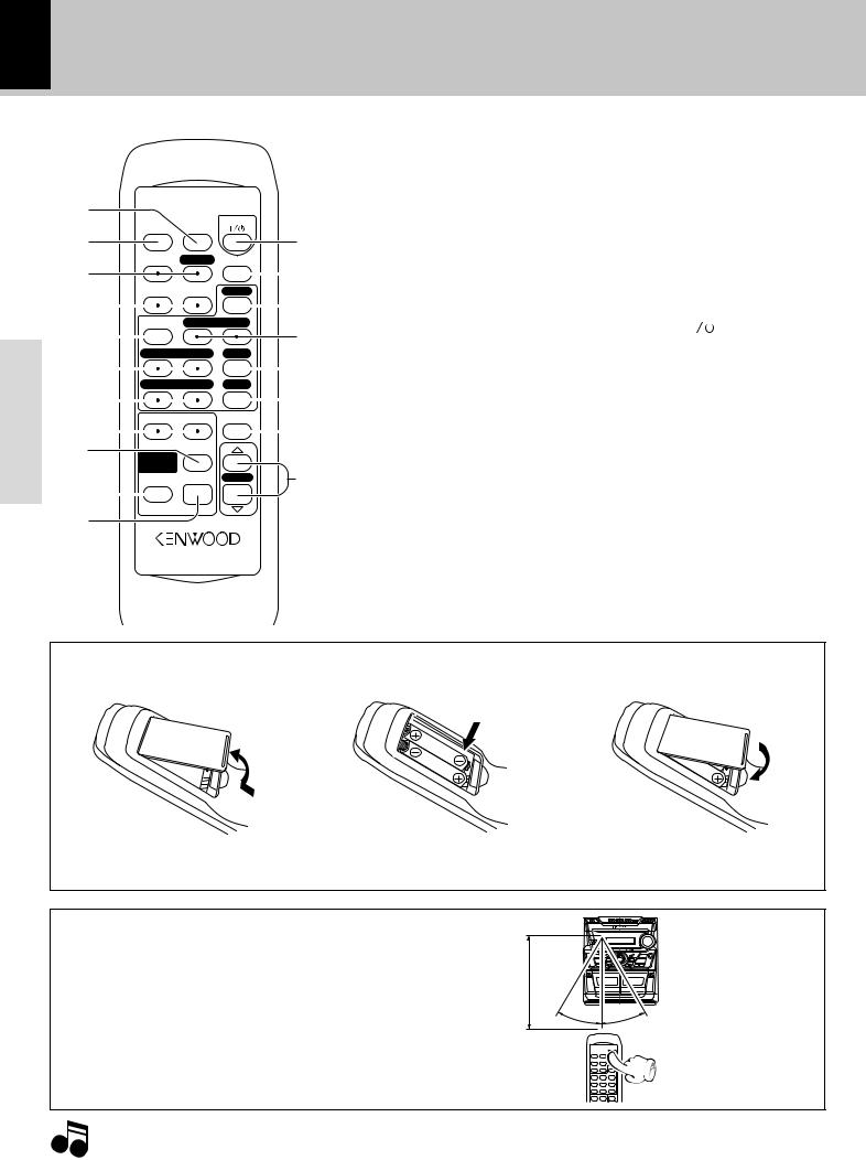
12 Operation of remote control unit
XD SERIES (En)
Preparation
The keys on the remote control unit with the same names as on the main unit have the same function as the keys on the main unit.
|
|
|
|
|
|
|
|
|
|
|
1SLEEP key |
|
8MULTI CONTROL keys |
% |
|||
1 |
|
|
|
|
|
|
|
|
|
|
Key for setting the sleep timer |
The left and right keys have the |
|||||
|
|
|
|
|
POWER |
|
|
|
› |
same functions as the |
MULTI |
||||||
|
TIME |
|
|
|
|
||||||||||||
2 |
SLEEP |
|
|
|
|
2TIME key |
& |
CONTROL jog dial on the main |
|||||||||
|
|
|
|
|
|
|
|
@ |
|||||||||
3 |
SOUND |
EX.BASS |
INPUT |
|
|
Press to switch the time informa- |
unit. |
|
|||||||||
|
|
|
|
|
|
|
|
|
# |
tion on the CD player unit. |
|
9SELECT key |
% |
||||
|
|
|
|
|
|
|
|
|
|
||||||||
4 |
RANDOM |
REPEAT |
BAND |
|
$ |
3SOUND key |
% |
0MENU key |
% |
||||||||
|
|
|
|
|
|
|
|
|
Switching between FLAT/JAZZ/ |
!ENTER key |
% |
||||||
DISC SKIP |
A/B TAPE 3 |
|
|||||||||||||||
5 |
% |
POP/ROCK |
|
@POWER ( |
|
) key |
$ |
||||||||||
|
|
||||||||||||||||
|
|
|
|
|
|
|
|
EX.BASS key |
% |
Power ON/OFF switching is ex- |
|||||||
1 TUNING ¡ 6 |
|||||||||||||||||
|
|
|
|||||||||||||||
6 |
|
^ |
4RANDOM key |
¡ |
ecuted. |
|
|||||||||||
|
|
|
|
|
|
|
|
|
|
||||||||
4 P.CALL ¢ |
7 |
|
Used for CD random playback. |
#INPUT key |
$ |
||||||||||||
|
|
|
|||||||||||||||
|
|
|
REPEAT key |
) |
$BAND key |
™ |
|||||||||||
7 |
|
|
|
|
|
|
|
|
|
& |
|||||||
|
|
|
|
|
|
|
|
|
|||||||||
|
2 |
|
3 |
MUTE |
|
|
Used for CD repeat playback. |
%TAPE A/B key |
¢ |
||||||||
|
|
|
* |
5DISC SKIP key |
& |
Tape playback (£) key |
|
||||||||||
8 |
|
|
|
|
|
|
|
|
|
|
|||||||
|
|
|
|
|
|
|
|
|
|
||||||||
9 |
MULTI |
SELECT |
|
|
|
|
6TUNING (1, ¡) keys |
|
^(CD) Play/pause (6) key^ |
||||||||
|
|
|
|
|
|
|
&™ |
&Stop (7) key |
^ |
||||||||
|
CONTROL |
|
|
VOLUME |
( |
||||||||||||
|
MENU |
ENTER |
Used for reception frequency tun- |
*MUTE key |
% |
||||||||||||
0 |
|
|
|
|
|
|
|
|
|
|
|||||||
|
|
|
|
|
|
|
|
|
|
ing and as CD search keys. |
|
Used for temporary muting |
|||||
|
|
|
|
|
|
|
|
|
|
|
|||||||
|
|
|
|
|
|
|
|
|
|
|
|
||||||
! |
|
|
|
|
|
|
|
|
|
|
7P.CALL (4, ¢) keys |
|
(VOLUME key |
$ |
|||
|
|
|
|
|
|
|
|
|
|
|
*™ |
|
|
|
|
||
|
|
|
|
|
|
|
|
|
|
|
|
|
|
|
|||
|
|
|
|
|
XD |
|
|
|
|
Used to call preset broadcasting |
|
|
|
|
|||
|
REMOTE CONTROL UNIT RC-352 |
|
|
stations and as CD skip keys. |
|
|
|
|
|||||||||
Loading batteries
1 Remove the cover. |
2 Insert batteries. |
3 Close the cover. |
 1
1
2
÷Insert two R6 (“AA”-size) batteries following the polarity indications.
Operation
Plug the power cord into the mains power outlet and press the on/standby ( 

 POWER) key of the remote control unit to turn power ON. After the power has been turned ON, press the desired key.
To turn power off, press the on/standby ( 

 POWER) key again.
÷When pressing more than one remote control keys successively, press the keys securely by leaving an interval of 1 second or more between keys.
Remote sensor
6m |
A |
B |
30 |
° |
° |
30 |
||
|
|
Operating range (approx.)
|
1. |
The provided batteries are intended for use in operation checking, and their service life may be short. |
Notes |
2. |
When the remote controllable distance becomes short, replace both of the batteries with new ones. |
|
3. |
If direct sunlight or the light of a highfrequency fluorescent lamp (inverter type, etc.) is incident to the remote sensor, malfunction |
may occur. In such a case, change the installation position to avoid malfunction.
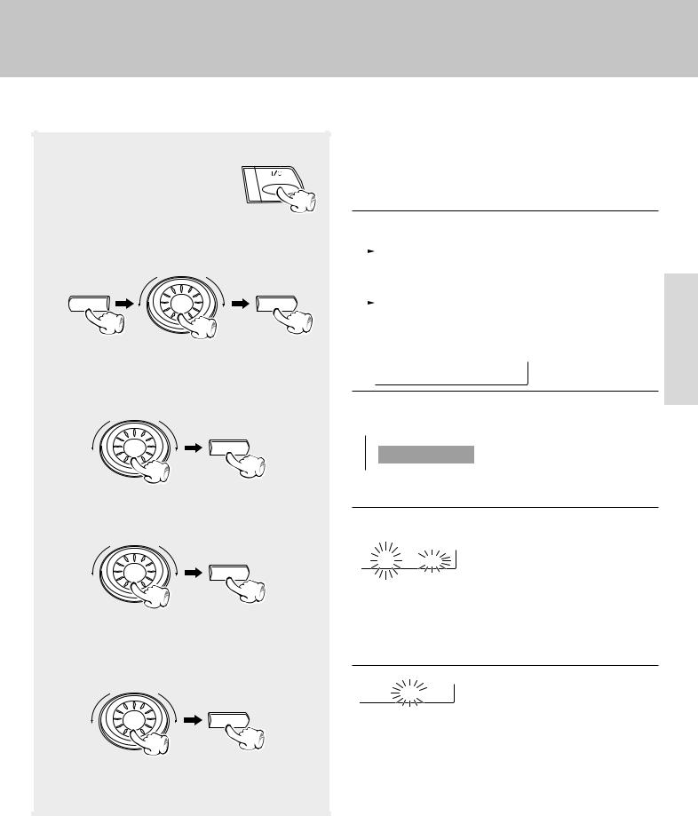
Clock adjustment
|
|
13 |
Adjust the clock before setting the timer. |
||
|
|
|
XD SERIES (En) |
|
|
This unit incorporates a clock function. Be sure to adjust the correct time before using the timer function. The time is displayed only while the power is off.
1Switching the power ON.
ON/STANDBY
2Select “Clock Options”.
MENU |
SELECT |
3Select “Adjust Time”.
SELECT
4Enter the figure of hour.
SELECT
To decrease the |
To increase |
figure |
the figure |
5Enter the figure of minute.
SELECT
To decrease |
To increase |
the figure |
the figure |
The following items can be selected by turning the |
|
|||||||
MULTI CONTROL jog dial. |
|
|||||||
|
|
|
(“CD Program Play”) |
|
||||
|
|
|
|
|||||
|
|
|
(“Recording Options”) |
|
||||
|
|
|
“Sound Options” |
|
||||
|
|
|
|
|
|
|||
|
|
|
“Clock Options” |
|
Preparation |
|||
|
|
|
|
|||||
÷ The display contents change according to the operation mode. |
||||||||
|
||||||||
|
|
|
+Scrolled display (Clock Options) |
|
||||
|
|
|
C l o c k |
|
O p ti |
|
||
|
|
|
|
|
||||
The following items can be selected by turning the MULTI CONTROL jog dial.
 “Sleep Time”
“Adjust Time”
 “Timer”
Example: Adjustment to 8:45
|
AM12ÔAM1ÔAM2... |
8 : 0 0 am |
PM1ÔPM2...ÔAM12 ... |
|
÷The time display starts to blink.
÷Press the SELECT key. The hour is entered and the minute display starts to blink.
8 : 4 5 am |
00Ô01Ô02 59Ô00Ô01 |
|
÷By turning the Jog dial and displaying "Return," you can return to the previous step and do a procedure over again.
÷To adjust correct time, press the ENTER key at the same moment as a time announcement.
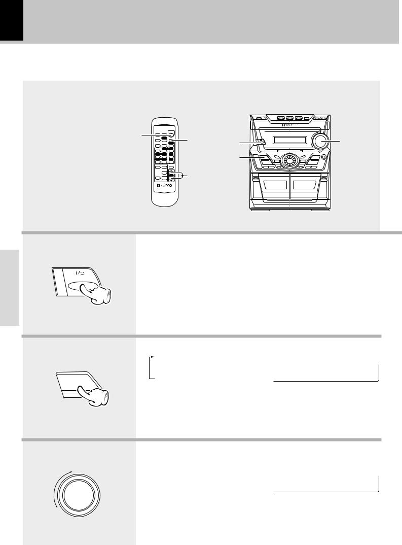
14 Let's put out some sound
Basic use method
1 |
|
POWER |
2 |
|
|
|
TIME |
SLEEP |
|
|
|
|
SOUND |
EX.BASS |
INPUT |
1 |
|
|
RANDOM |
REPEAT |
BAND |
||
|
DISC SKIP |
A/B TAPE 3 |
|||
|
1 TUNING ¡ 6 |
|
2 |
||
|
4 P.CALL ¢ |
7 |
|
|
|
|
2 |
3 |
MUTE |
|
|
|
MULTI |
SELECT |
|
3 |
|
|
|
|
|
||
|
CONTROL |
|
|
|
|
|
MENU |
ENTER |
VOLUME |
|
|
|
|
XD |
|
|
|
XD SERIES (En)
3
 MULTI CONTROL
APLAY |
REC/ |
PLAYB |
Operation
1. Switching the power ON
If a disc has already been loaded in the CD player and the power is OFF, simply pressing the CD play key turns power automatically ON and starts playback.
ON/STANDBY
2. Selecting the desired output
1 TUNER (Radio) |
™ |
When CD has been selected. |
2 CD |
^ |
|
3 TAPE |
¢ |
C D 0 1 |
0 :00 |
4 AUX (External input) |
9 |
|
|
INPUT
3. Volume adjustment
To increase volume
VOLUME |
Volume display |
|
|
V o l u m e |
91 |
To decrease volume
 Loading...