

Page 1

.
WD-ZS10
PROGRAMMING SOFTWARE
USER GUIDE
B5A-1816-00(E)
Page 2

1
INTRODUCTION
1.1
CONTENTS
1 INTRODUCTION 1
1.1 CONTENTS 1
1.2 How to Read This User Guide 2
Symbols Used 2
Content of This User Guide 2
1.3 Operating Environment 2
Compatible PCs 2
Precautions 3
1.4 Programming Software WD-ZS10 3
2 PREPARATION 4
2.1 Connection 4
2.2 Installation Procedures 5
Installing Applications 5
Installing the USB Driver 9
2.3 Uninstallation Procedures 9
3 STARTING THE APPLICATION 10
3.1 Starting Programming Software WD-ZS10 10
3.2 Launcher Dialog 11
4 USING THE APPLICATION 12
4.1 Device Registration 12
Wireless Registration of Device 12
Wired Registration of Device 16
4.2 System Setup 25
Basic Operations 25
Importing and Writing System Setup 29
WD-K10PBS (Base Station Mode) Setup 32
WD-K10PBS (Transceiver Mode)/ WDK10TR Setup 40
WD-K10BS Setup 46
4.3 Log Display 52
Opening Log Display 52
4.4 Connection Status Check 53
Opening Connection Status Display 53
4.5 Wireless Settings Update 56
Writing Settings 57
4.6 Firmware Update 62
Opening Firmware Update Screen 62
Updating Firmware Via Wired 63
Updating Firmware Via Wireless 66
4.7 Turning On/Off the Device Power 70
Turning On/Off the Power of WD-K10BS 70
Turning On/Off the Power of WDK10PBS/ WD-K10TR 71
5 OTHERS 72
5.1 Troubleshooting 72
CONTENTS
1
Page 3

Precautions
Note
1 INTRODUCTION
1.2 How to Read This User Guide
1.2
How to Read This User Guide
Symbols Used
Describes precautions concerning the operation of this product.
Describes reference information, such as functions and usage restrictions of this product.
Content of This User Guide
rights reserved by JVC KENWOOD Corporation. Unauthorized duplication or reprinting of this user guide, in whole or
All
0
in part, is strictly prohibited.
Other product and company names included in this user guide are trademarks and/or registered trademarks of their
0
respective companies. Marks such as ™ and ® have been omitted in this user guide.
Illustrated designs, specifications and other contents of this user guide are subject to change for improvement without
0
prior notice.
For details on setup terms and setup methods, please refer to the Instructions or Design Manual for the DECT Intercom
0
System WD-K10 series.
Unless otherwise stated, screen shots of Windows 7 are used in the description of this user guide.
0
1.3
The programming software WD-ZS10 has been verified to run on the following PC environments. The operating environment
is accurate as at September 2016. For the latest operating environment, please check with the KENWOOD dealer.
Operating Environment
Compatible PCs
OS: Windows 7
Windows 8.1
Windows 10
Microsoft .NET Framework 4.5 or 4.6
*For Windows 8.1, run the software by switching from modern UI to desktop screen.
*For Windows 10, use the software in desktop mode.
CPU, memory: Environment recommended in each OS
Display: 1024 x 768 resolution or higher
HDD: HDD capacity of 50 MB and above is required for installation of applications
Interface: USB
PC side: Type A
WD-K10PBS/WD-K10TR/WD-K10BS side: Micro B
Note
0
PC
specifications mentioned are guidelines for optimal application usage. We do not guarantee the operation. PCs that
satisfy the operating environment conditions may not operate optimally depending on your usage situation.
0
Please install Microsoft .NET Framework from Microsoft’s website.
0
Microsoft and Windows are either registered trademarks of Microsoft Corporation in the United States and/or other
countries.
CONTENTS
2
Page 4

1 INTRODUCTION
1.3 Operating Environment
Precautions
Login to OS
Set user rights to Administrator during use of applications.
Starting Up Applications
Do not switch users when starting up applications.
Using Applications
Do not use the Power Save or Resume functions in PCs in which the programming software WD-ZS10 has been installed.
Communication status and communication data may become unstable. (The Power Save and Resume functions may be
named differently depending on your PC.)
1.4
The programming software WD-ZS10 is an application to configure various settings and to manage connection for the DECT
Intercom System WD-K10 series.
It allows you to import and change system settings for each device, and save these settings in a file.
0
Settings for the connected device can be written.
0
Other devices can be registered as a sub unit to the connected device.
0
Device firmware can be updated.
0
Applicable models:
0
- PORTABLE BASE WD-K10PBS
- TRANSCEIVER WD-K10TR
- BASE STATION WD-K10BS
Note
0
In this user guide, WD-K10PBS, WD-K10TR, and WD-K10BS are indicated as “device”.
0
Please use the latest version for the programming software WD-ZS10.
Programming Software WD-ZS10
CONTENTS
3
Page 5
2
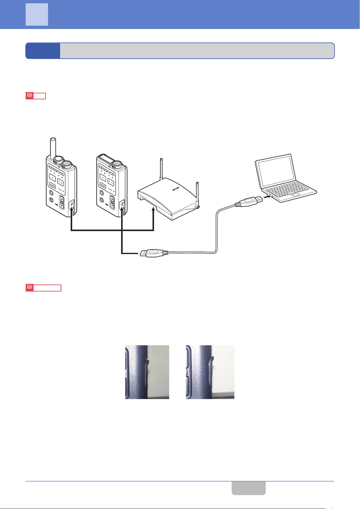
PTT
PTT
Programming software WD-ZS10
PC side:
Ty p e A
Portable base
WD-K10PBS
Transceiver
WD-K10TR
Base station
WD-K10BS
Device side:
Micro B
Connect to any one of these devices
USB cable
(A type - Micro B type) (sold separately)
(within 2m)
䛆㻻㻷䛇 䛆㻺㻳䛇
PREPARATION
2.1
Connect the PC installed with the programming software WD-ZS10 and a device (WD-K10PBS, WD-K10TR, WD-K10BS)
of the DECT Intercom System WD-K10 series.
Note
0
Communication is disabled if two or more devices are connected to the PC. Connect only one device during
communication.
Connection
Precautions
Be sure to attach the device cap on WD-K10PBS and WD-K10TR after removing the USB cable from the data setup
0
devices.
When attaching the device cap, push it in and ensure that it is not loose.
Loose caps may affect the waterproofing performance.
CONTENTS
4
Page 6
2 PREPARATION
2.2 Installation Procedures
2.2
To install or uninstall the programming software WD-ZS10, log in to the PC as a user with Administrator rights.
Refer to the help of your OS for setting Administrator rights and user accounts.
Note
0
Before installing, uninstall the antivirus utility. The antivirus utility may affect the installation of WD-ZS10. A personal
firewall function may be installed in Windows 7, Windows 8.1, Windows 10, and antivirus software. If this function is
set to “ON”, the software may not be installed properly. Set the function to “OFF”.
Installation Procedures
Installing Applications
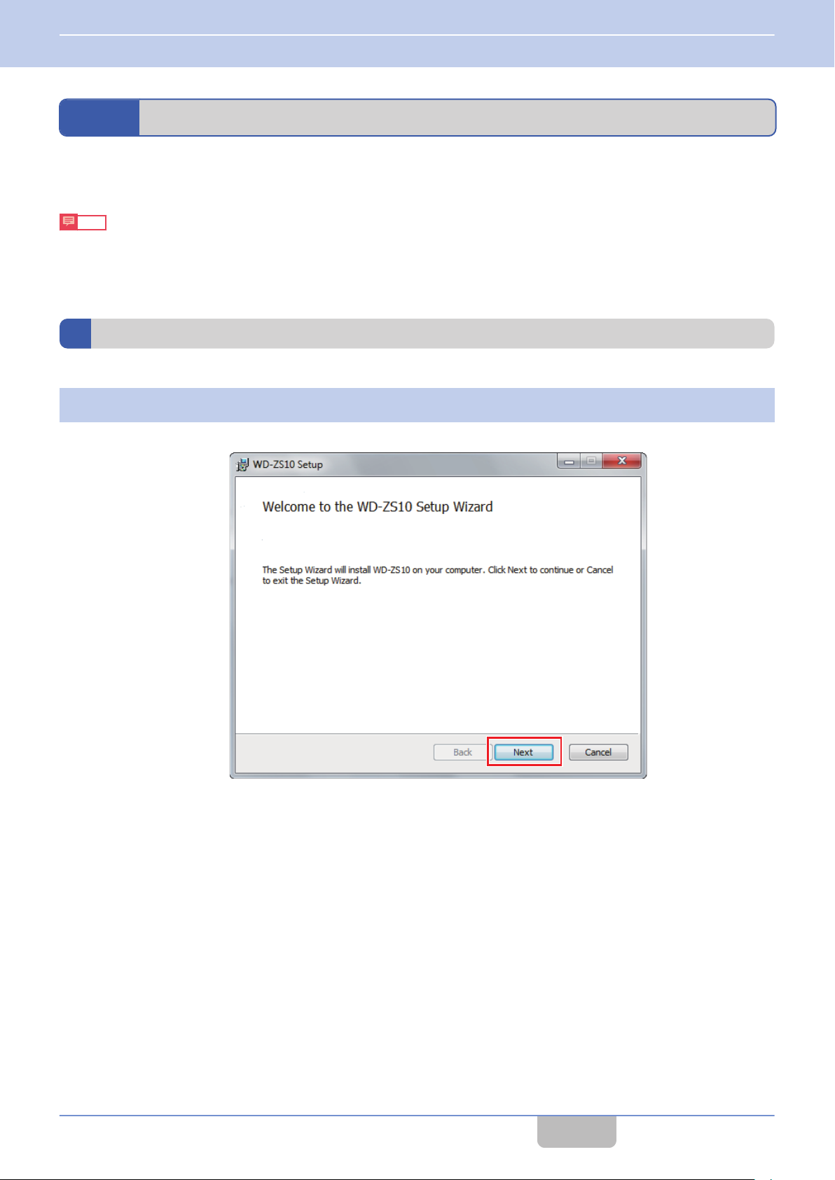
Start the installer and click [Next].
1
Double-click “Setup.msi” in the WD-ZS10 folder from the downloaded “WD-ZS10” file set to start the installer.
CONTENTS
5
Page 7
2 PREPARATION
2.2 Installation Procedures
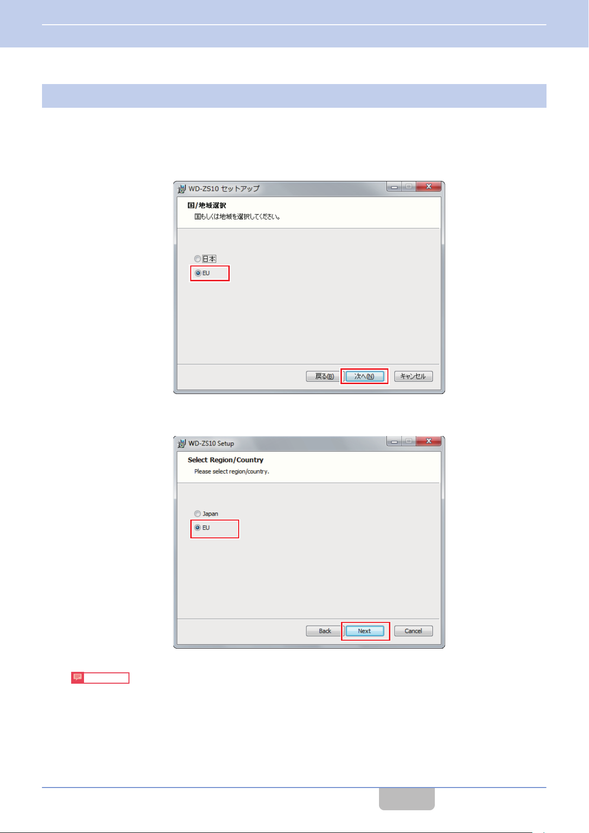
Select a country/region.
2
Select a country/region where WD-ZS10 is to be used.
The available options are “EU” and “Japan”.
If the OS language is Japanese, the Region/Country selection screen is displayed in Japanese. Otherwise, the screen
will be displayed in English.
[When OS language is Japanese]
Select “EU” from “Region/Country” and click [Next].
[When OS language is not Japanese]
Select “EU” from “Region/Country” and click [Next].
Precautions
If “Japan” is selected in the Region/Country selection screen, Japanese-denoted applications used in Japan will
0
be installed.
You are not allowed to switch the display language after installation.
0
Reinstall the application if you wish to switch the display language.
You cannot install both Japanese and English versions of WD-ZS10 on one PC.
0
CONTENTS
6
Page 8
2 PREPARATION
2.2 Installation Procedures
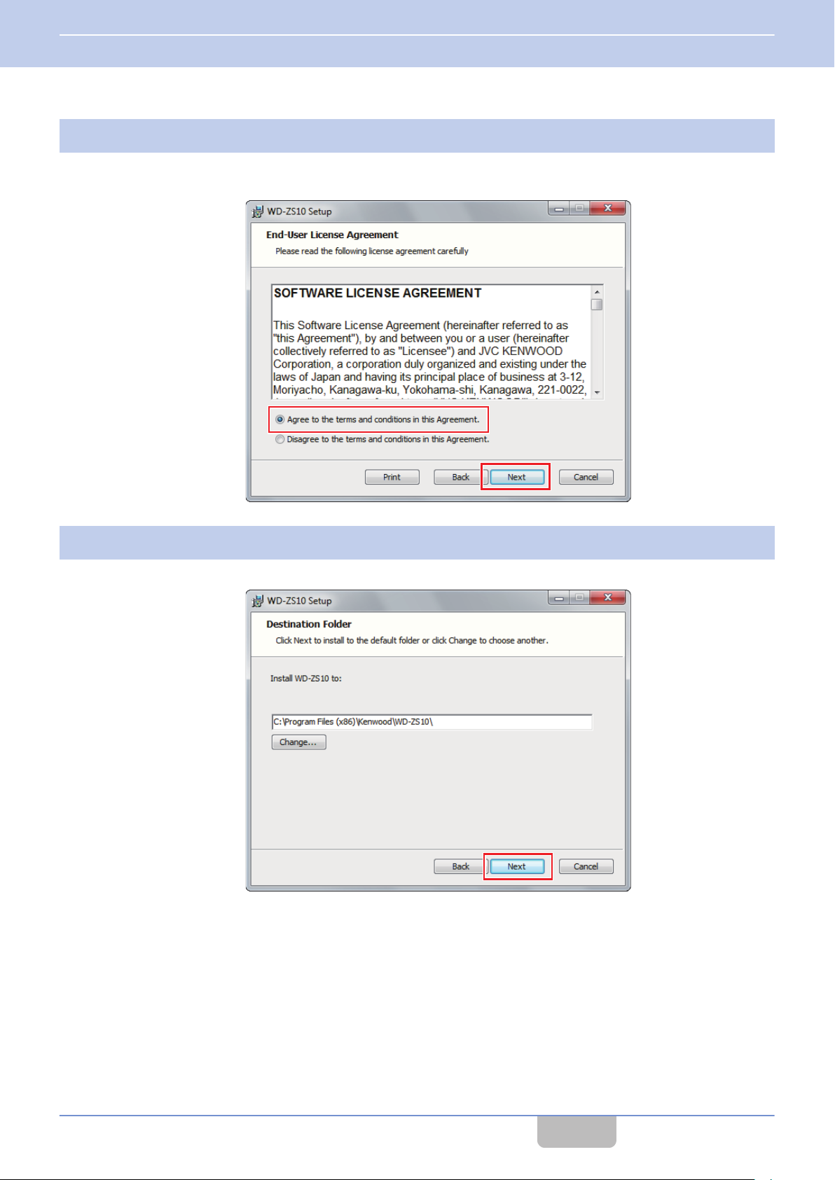
Check the “SOFTWARE LICENSE AGREEMENT”.
3
To agree, select [Agree to the terms and conditions in this Agreement.] and click “Next”.
To disagree, select [Disagree to the terms and conditions in this Agreement.] and click “Cancel” to cancel installation.
Select the folder for installation and click [Next].
4
To change a folder, click [Change] and specify the folder.
CONTENTS
7
Page 9
2 PREPARATION
2.2 Installation Procedures
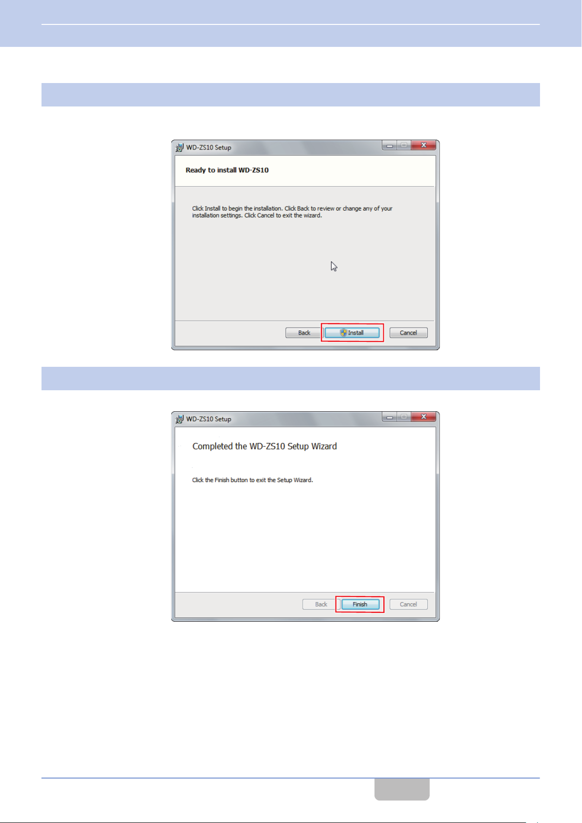
Click [Install].
5
Installation begins.
To change the entered contents, click [Back] and change the settings.
Click [Finish].
6
Installation is complete.
CONTENTS
8
Page 10

2 PREPARATION
2.2 Installation Procedures
Installing the USB Driver
When a device of the DECT Intercom System WD-K10 series is connected to a PC that is turned on, the required driver will
be automatically installed.
Connect properly according to the device to be used.
on page 5
2.3
Follow the procedures below to uninstall the programming software WD-ZS10.
Select “Programs and Features” from the Windows control panel.
1
Select “WD-ZS10” from the list of currently installed programs to uninstall.
2
Check the uninstallation message and click [OK].
3
Uninstallation Procedures
CONTENTS
9
Page 11
3
STARTING THE APPLICATION
3.1
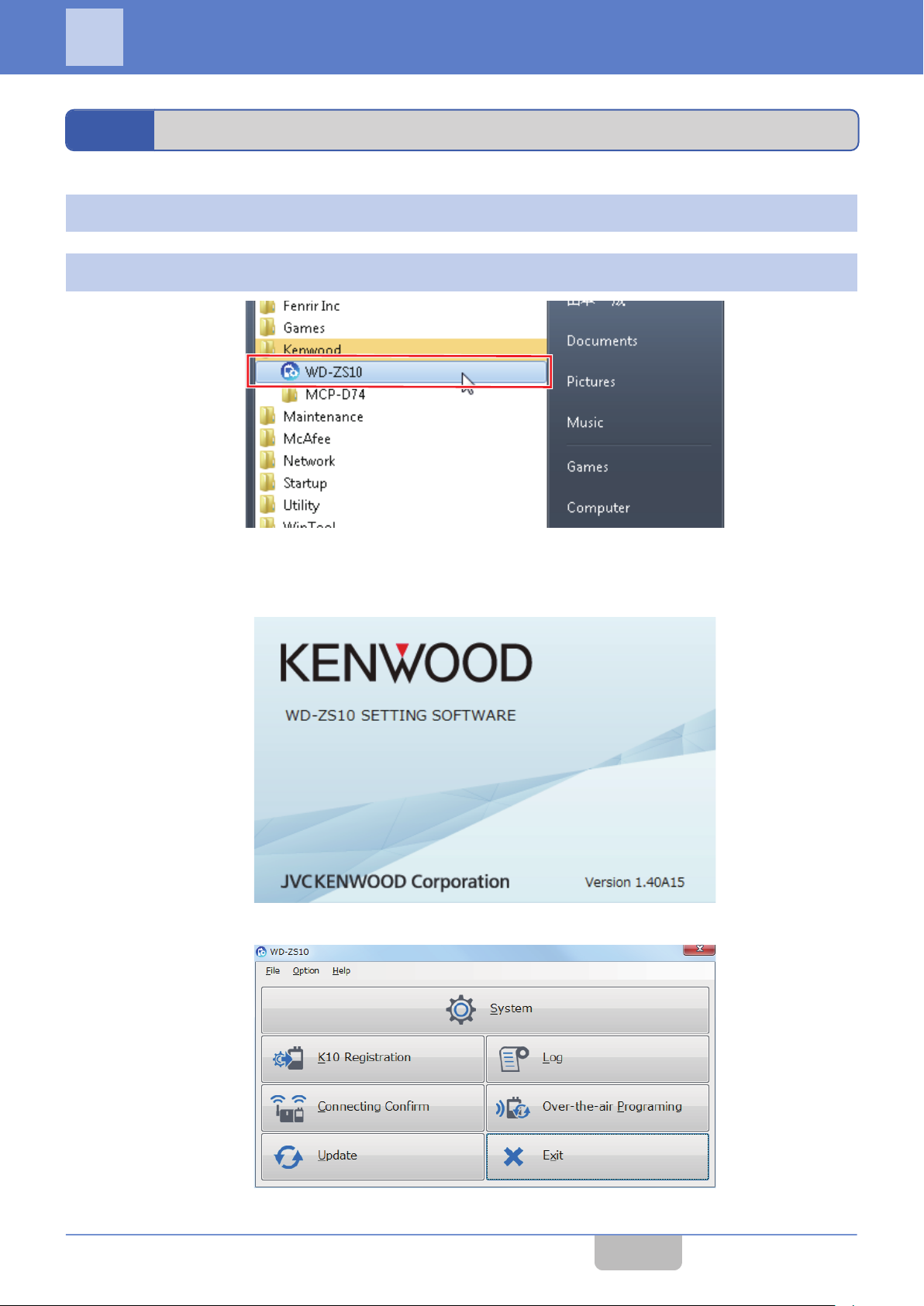
Click in the following order at the Start Menu: “Start”-”All Programs”-”Kenwood”.
1
Click “WD-ZS10”.
2
*Screen shots are from Windows 7.
A KENWOOD logo display screen appears and the launcher dialog will start up.
[KENWOOD logo display screen]
Starting Programming Software WD-ZS10
[Launcher dialog]
CONTENTS
10
Page 12
A
B
3 STARTING THE APPLICATION
3.2 Launcher Dialog
3.2
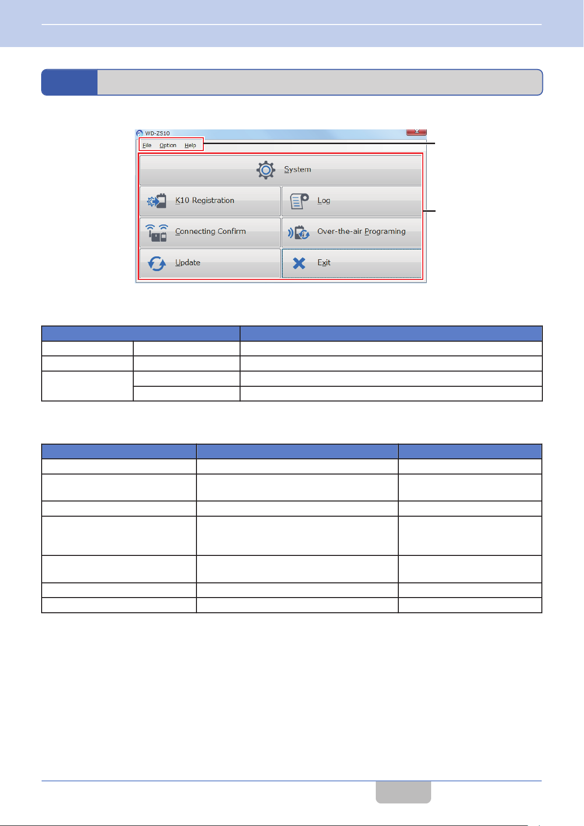
Launcher Dialog
Launcher Dialog Screen
Menu
A
The following functions are available in the menu bar at the top of the launcher dialog.
Menu Content
File Exit Exits the application.
Option Service Mode This is a service menu. It is not used normally.
Help
Help Displays the user guide (this manual) of the application.
About WD-ZS10 Displays the version information of the application.
Tab
B
Click a key in the launcher dialog to activate various functions and setup screens of WD-ZS10.
Tab Function Reference Page
System Starts System setup. on page 25
K10 Registration
Log For checking the event or error logs. on page 52
Connecting Confirm
Over-the-air Programming
Update Updates the firmware of the device. on page 62
Exit Exits WD-ZS10. ―
Performs wired or wireless registration of
devices.
For checking information of the currently
connected base unit and sub unit connected to
each slot.
Updates settings of a sub unit in wireless
communication.
on page 12
on page 53
on page 56
CONTENTS
11
Page 13
4
USING THE APPLICATION
4.1
To operate the DECT Intercom System WD-K10 series, you must register the information of the other party in communication
with the respective devices (for a base unit, other party refers to the sub unit; for a sub unit, other party refers to the base
unit).
There are two types of registration methods: “Wireless Registration” and “Wired Registration”.
When constructing the system, perform “sub unit registration to base unit” first, followed by “base unit registration to sub
unit”.
This section describes the registration method of devices that use WD-ZS10.
Note
0
You
of each device.
0
Perform device registration for each device one at a time.
Device Registration
can register a device by using only the device and not WD-ZS10. For details, please refer to the instruction manual
Wireless Registration of Device
Use wireless communication to register the information of a sub unit to a base unit (WD-K10PBS (Base Station Mode) or
WD-K10BS) that is connected to a PC.
Note
0
A base unit cannot be registered to a sub unit via Wireless Registration in WD-ZS10. To register a base unit to a sub
unit, use Wired Registration ( on page 16) or perform sub unit registration using a device.
0
If a device is in All Call mode, sub unit registration via wireless communication is not allowed.
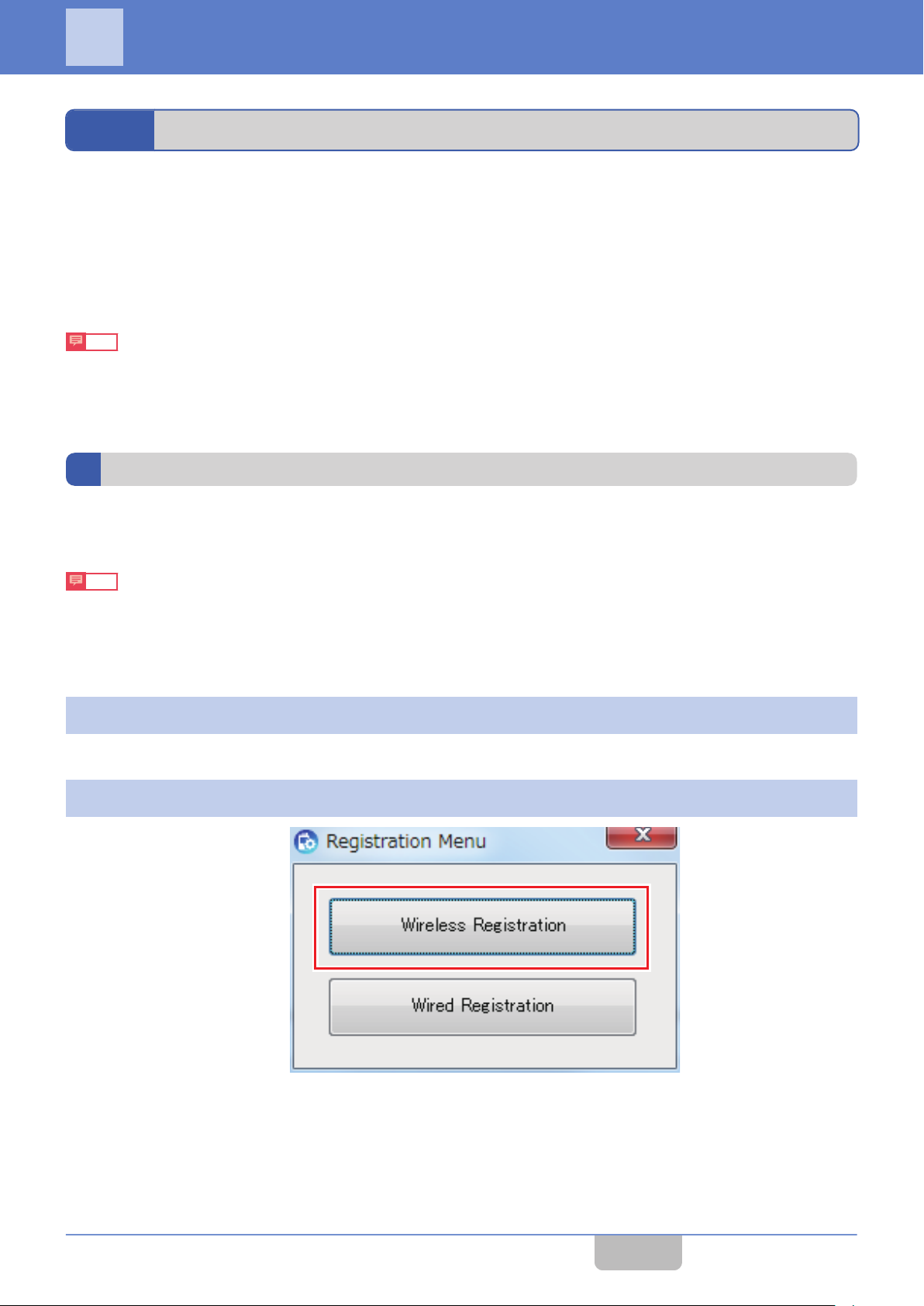
Click “K10 Registration” in the launcher dialog.
1
The Registration Menu opens.
Click [Wireless Registration].
2
The Wireless Registration screen opens.
CONTENTS
12
Page 14
A
B
C
D
4 USING THE APPLICATION
4.1 Device Registration
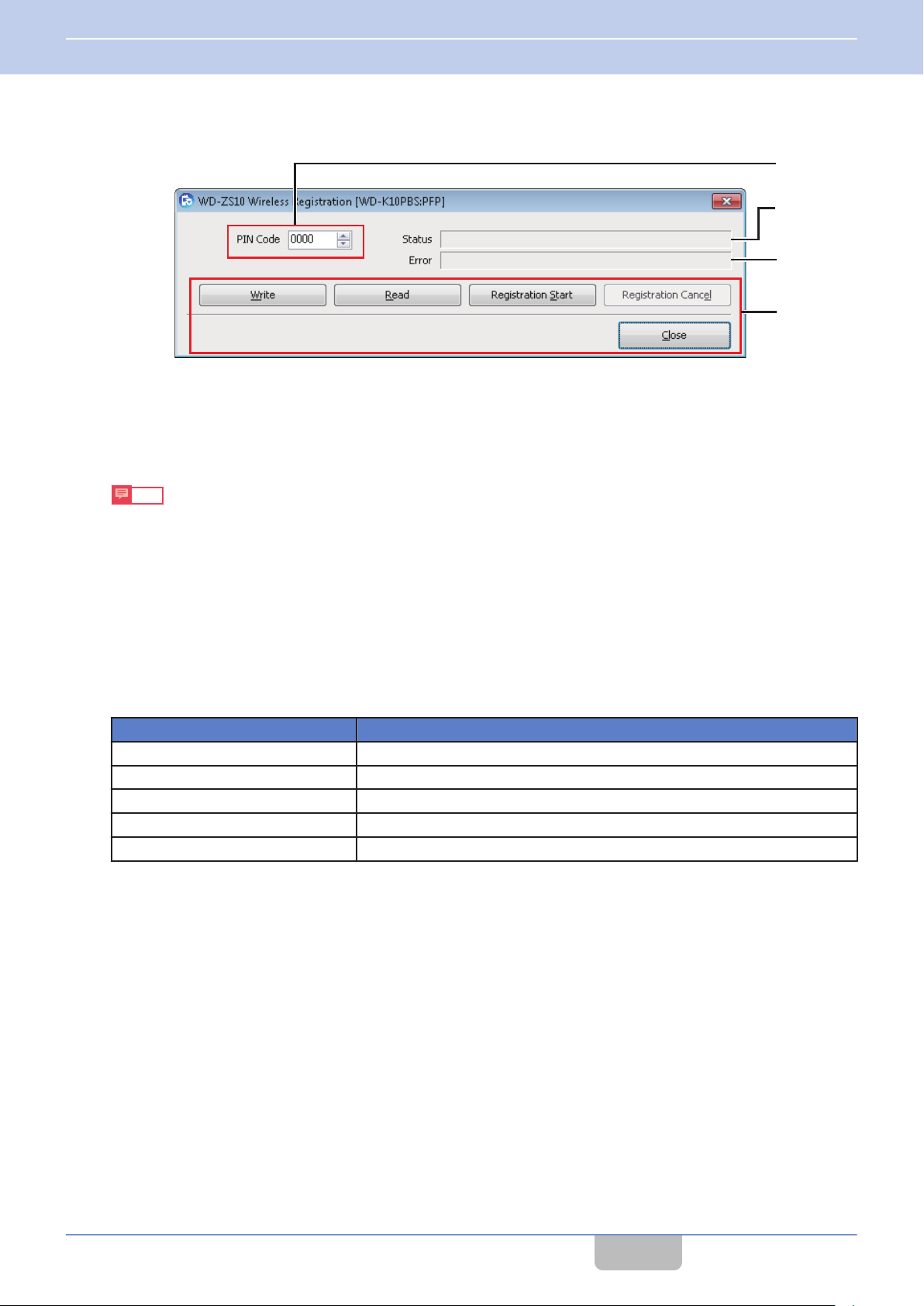
Wireless Registration Screen
PIN Code
A
This is a password to prevent unauthorized third-party usage of a device.
PIN code of the device connected to the PC will be imported automatically and displayed. You can edit and write
The
the PIN code to the device.
Note
0
Enter any 4-digit number for the PIN code.
0
Click [Write] to write the settings to the device.
Status
B
The status during the registration of a device is displayed.
Error
C
When an error has occurred during the registration of a device, an error message is displayed.
Operation Keys
D
Key Content
Write Writes the edited PIN code to the connected device.
Read Imports the PIN code of the connected device.
Registration Start Starts device registration for the connected device.
Registration Cancel Stops device registration.
Close Closes the Wireless Registration screen.
CONTENTS
13
Page 15
PTT
Status LED
[All Call]
key
[Power] key
Group LEDs
PTT
Status LED
Group LEDs
4 USING THE APPLICATION
4.1 Device Registration
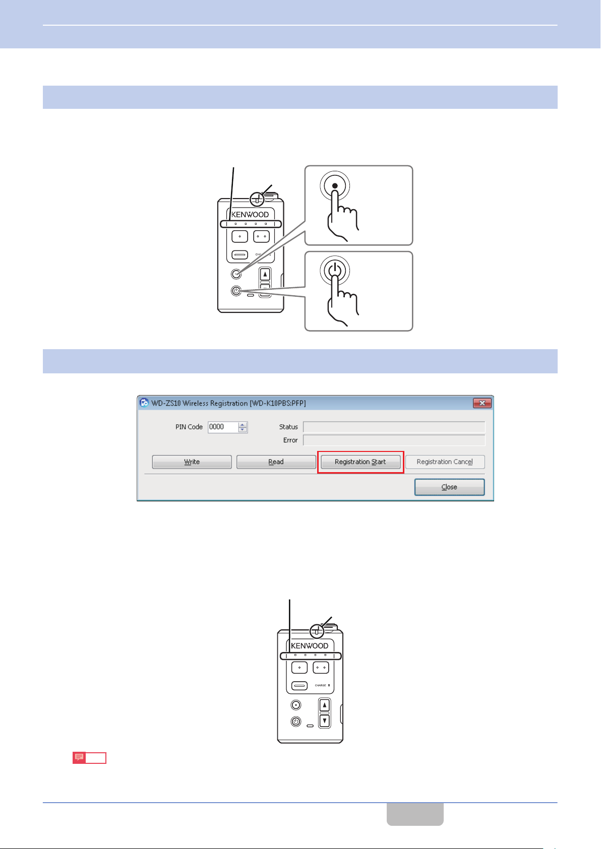
Activate the registration mode of the sub unit to be registered.
3
While pressing the [All Call] key of the sub unit, press and hold the [Power] key. The Status LED lights up in green.
Continue to press and hold until all the Group LEDs blink.
This activates the registration mode.
Click [Registration Start] at the Wireless Registration screen.
4
The base unit automatically switches to wireless registration mode. Device registration begins.
When registration is successful:
The Status LED of the sub unit lights up in green and all Group LEDs light up.
When registration has failed:
The Status LED of the sub unit lights up in green but all Group LEDs do not light up.
Turn off the power of the device. Return to step 3 and register again in registration mode.
Note
0
To stop registration midway, click [Registration Cancel].
CONTENTS
14
Page 16
4 USING THE APPLICATION
4.1 Device Registration
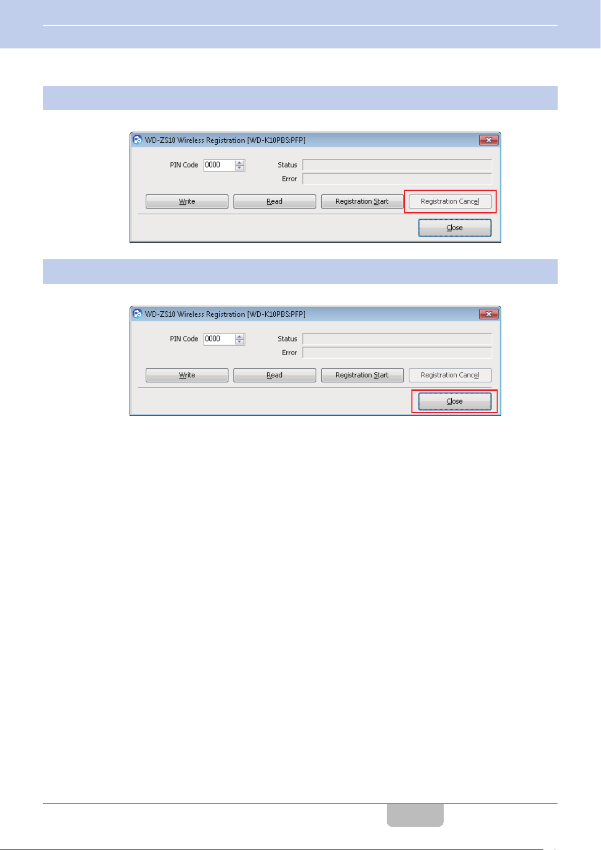
If registration of all devices is successful, click [Registration Cancel] at the Wireless Registration screen.
5
This stops the registration.
Click [Close].
6
Registration is complete.
CONTENTS
15
Page 17
4 USING THE APPLICATION
4.1 Device Registration
Wired Registration of Device
From the list of devices that has been imported in WD-ZS10 and where base unit and sub unit are connected to a PC,
register a sub unit to a base unit and vice versa. You can also delete devices from the list.
Note
0
Wired registration is useful when radio signals are poor or when they are not available.
0
Up to 6 base units can be registered to a sub unit. When constructing a system to run multiple base units, you can
connect
List of “K10 Registration” with the numbers in “Base Station Select” of System.
0
A sub unit cannot be registered to a sub base unit of a base link system. Register the sub unit to a main base unit.
0
A base unit cannot be registered to another base unit, and a sub unit to another sub unit.
1
a sub unit to a designated base unit every time, by matching the number sequence displayed in the Terminal
Connect a sub unit to a PC.
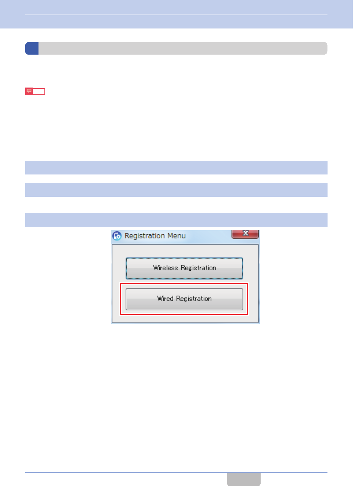
Click “K10 Registration” in the launcher dialog.
2
The Registration Menu opens.
Click [Wired Registration].
3
The Wired Registration screen opens.
CONTENTS
16
Page 18
AB C
D
4 USING THE APPLICATION
4.1 Device Registration
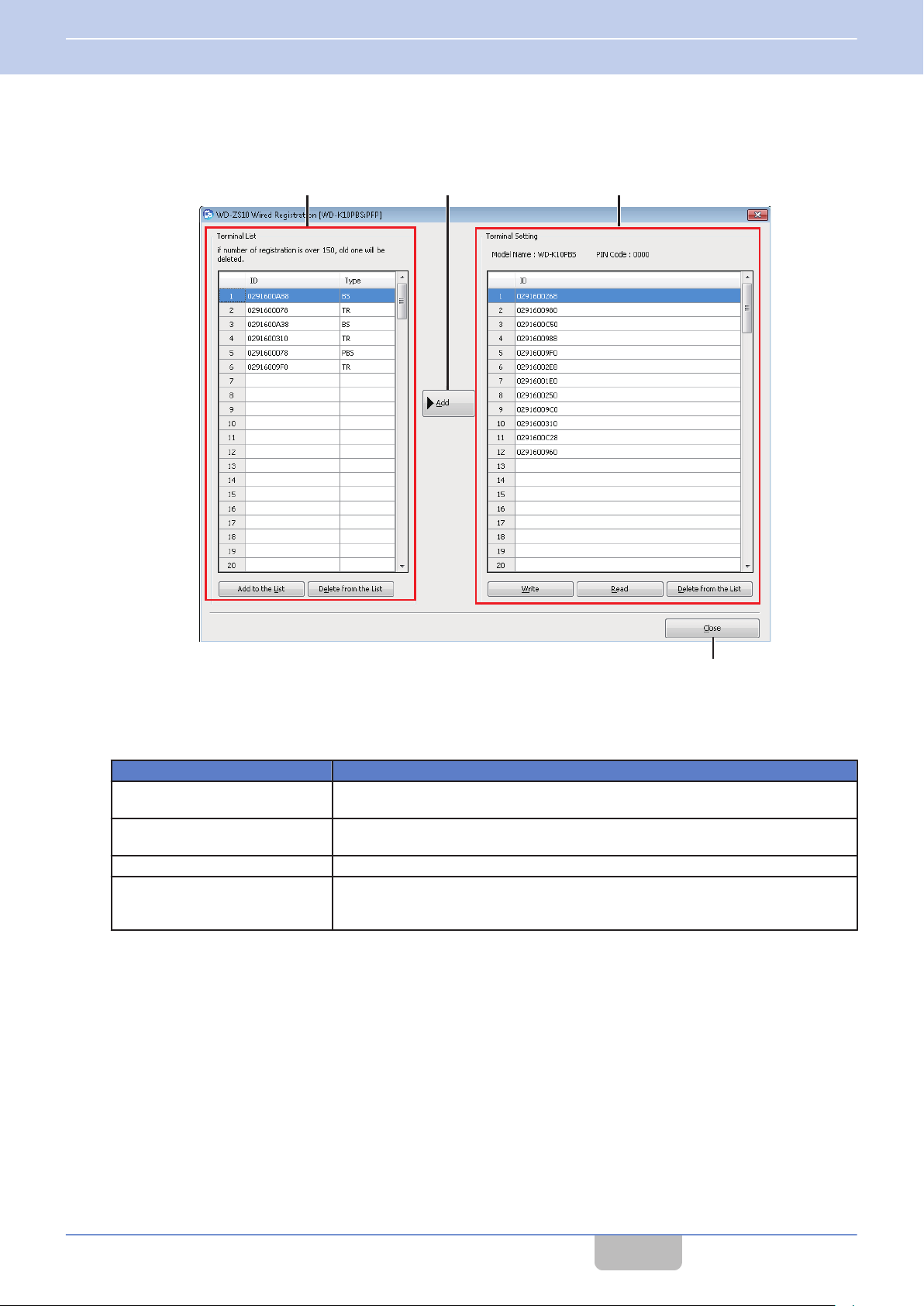
Wired Registration Screen
Terminal List
A
Information
You can add a selected device to the “Terminal Setting” list.
ID
Type
Add to the List Registers a device connected to the PC in the “List of Devices”.
Delete from the List
[Add] key
B
The selected device in the “Terminal List” will be added to the “Terminal Setting” list.
for up to 150 devices that were previously connected to the PC and imported in WD-ZS10 is displayed.
Item Content
The device ID is displayed.
Click on title cell “ID” in the Terminal List to sort the list in the order of the IDs.
The type of device is displayed.
PP (sub unit)/FP (base unit (base station))/PFP (base unit)
Select the ID of a displayed device and delete from the list. (Can make multiple
selections.)
A confirmation screen appears before deletion.
CONTENTS
17
Page 19
4 USING THE APPLICATION
4.1 Device Registration
Terminal Setting
C
The information of the base unit or sub unit that is registered in the device connected to a PC is displayed.
Item Content
Model Name The model name of the device connected to a PC is displayed.
PIN Code The PIN code of the device connected to a PC is displayed.
The device ID is displayed.
When a base unit is connected:
The IDs of up to 108 registered sub units are displayed.
ID
Write
Read
Delete from the List This deletes a selected device from the list.
When a sub unit is connected:
The IDs of up to 6 registered base units are displayed.
Device IDs are displayed in the order of registration. Click on the title cell “ID” to sort
the IDs in ascending, descending or ID registration order.
This writes the content of the edited “Terminal Setting” list to the device that is
connected to a PC.
This imports settings from the device connected to a PC. The model name, PIN code
and “Terminal Setting” list contents will be updated.
[Close] key
D
This closes the Wired Registration screen.
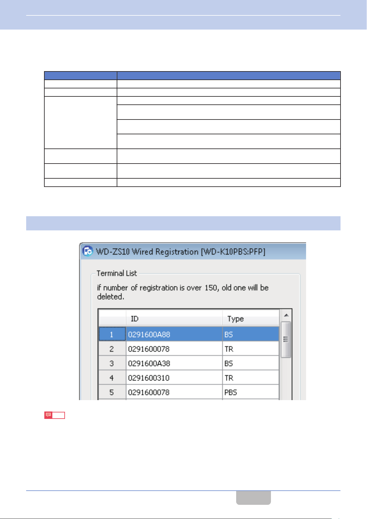
Check that the sub unit ID is registered in the “Terminal List” in the Wired Registration screen.
4
The sub unit ID is type PP.
Note
0
Registration of a sub unit ID to WD-ZS10 needs to be performed only once.
CONTENTS
18
Page 20
USB connection
PTT
4 USING THE APPLICATION
4.1 Device Registration
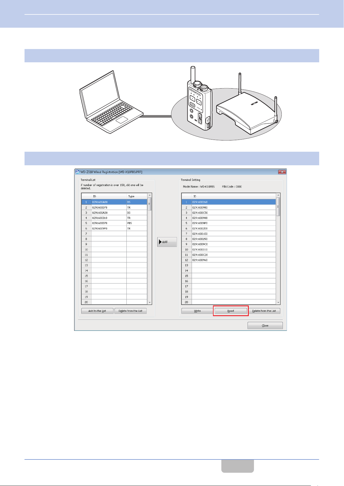
Connect a base unit to the PC.
5
Click [Read] in the Wired Registration screen.
6
CONTENTS
19
Page 21
4 USING THE APPLICATION
4.1 Device Registration
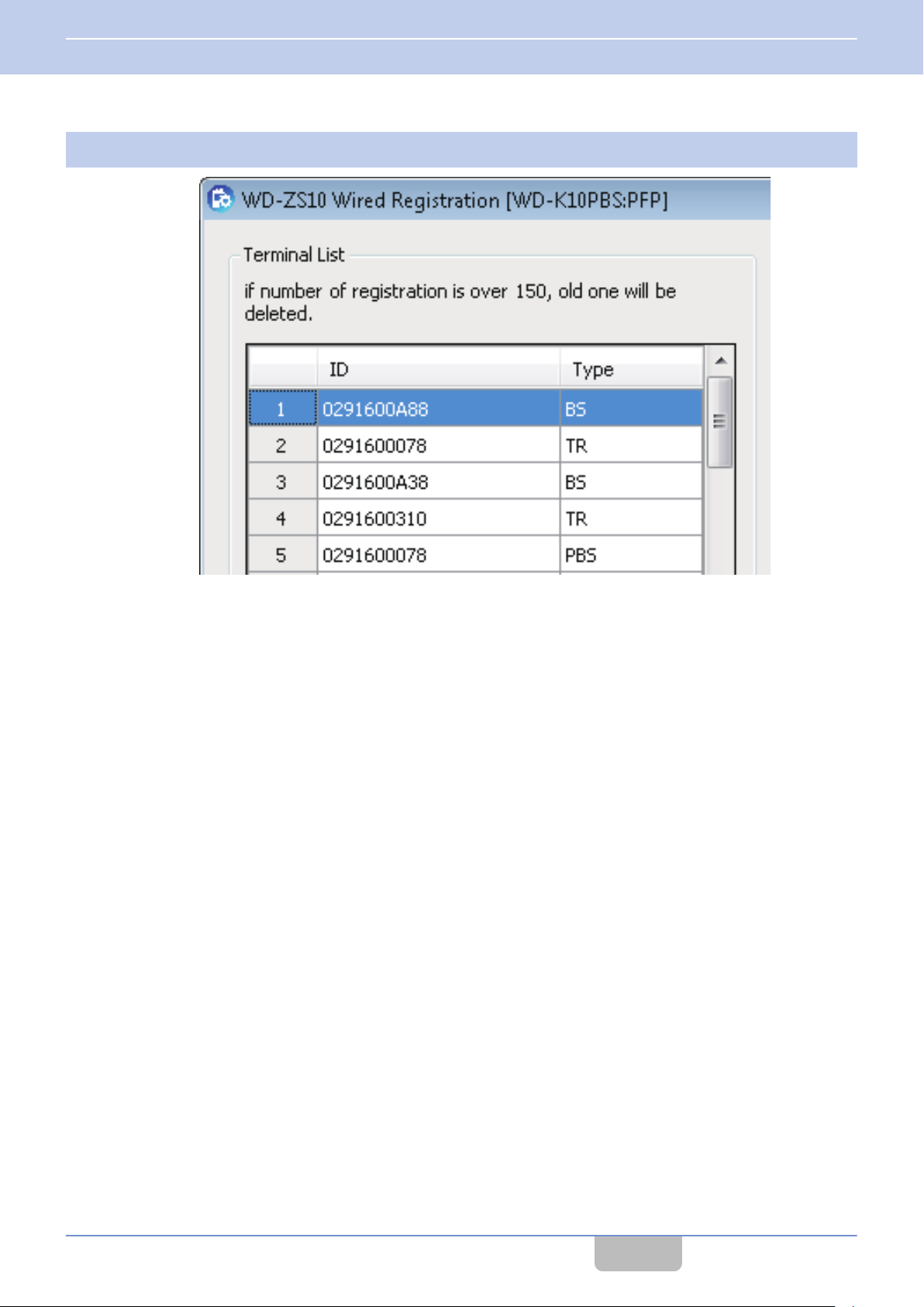
Select the ID of the sub unit to be registered from the “Terminal List” in the Wired Registration screen.
7
CONTENTS
20
Page 22
4 USING THE APPLICATION
4.1 Device Registration
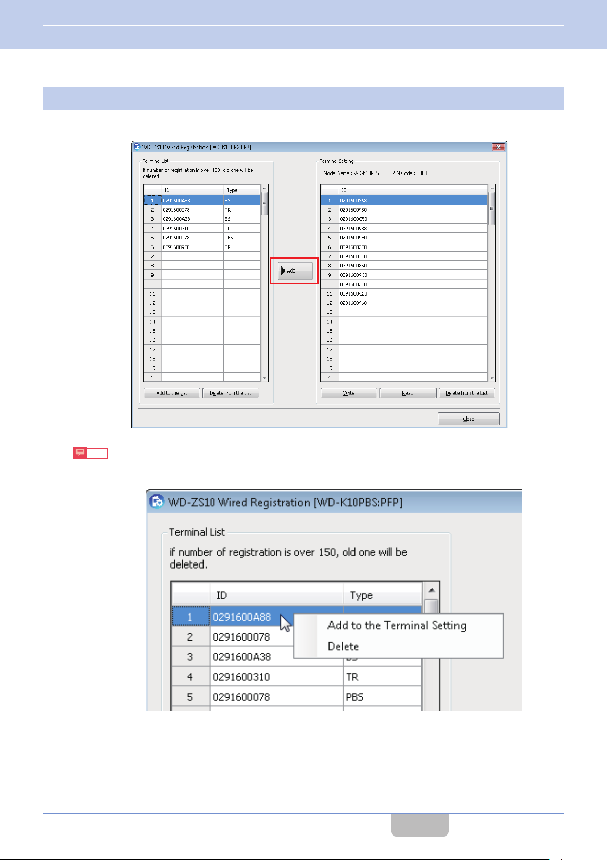
Click [Add] to add the device to the “Terminal Setting” list.
8
The ID of the selected sub unit is added to the “Terminal Setting” list. To add more devices that have been registered,
press the [Add to the List] key in the “Terminal List”, and repeat steps 5 to 6.
Note
0
Drag-and-drop
Terminal Setting” to add the device to the “Terminal Setting” list.
0
IDs of sub units that have been registered to the “Terminal Setting” list cannot be added.
the ID of the selected device, or right-click on the ID of the selected device and click “Add to the
CONTENTS
21
Page 23
USB connection
PTT
4 USING THE APPLICATION
4.1 Device Registration
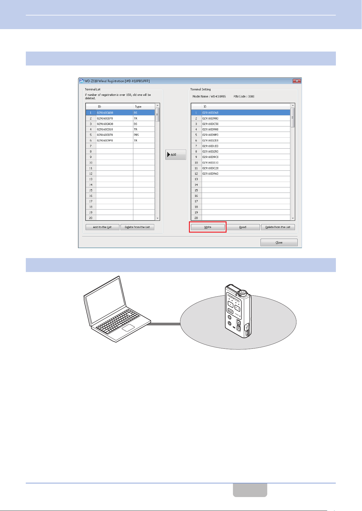
Click [Write].
9
The edited information of the sub unit will be written to the connected base unit.
Connect a sub unit to a PC.
10
CONTENTS
22
Page 24

4 USING THE APPLICATION
4.1 Device Registration
Click [Read].
11
Select the ID of the base unit to be registered from the “Terminal List” in the Wired Registration screen.
12
The base unit ID is type PFP or FP (base station).
Click [Add] to add the device to the “Terminal Setting” list.
13
The ID of the selected base unit is added to the “Terminal Setting” list.
CONTENTS
23
Page 25

Status LED
4 USING THE APPLICATION
4.1 Device Registration
Click [Write].
14
The edited information of the sub unit will be written to the connected base unit.
Turn on the power of the registered base unit and sub unit.
15
Once the power is turned on, the base unit and sub unit automatically communicate with one another. Communication
is complete once the Status LED of the sub unit blinks in green.
CONTENTS
24
Page 26

A
B
C
D
E
4 USING THE APPLICATION
4.2 System Setup
4.2
You can perform system setup for the DECT Intercom System WD-K10 series. You can import or write settings between
connected devices.
Note
0
Settings may differ depending on the model of the connected device.
0
Setup data can be saved and printed even when the device is not connected.
Click “System” in the launcher dialog.
1
System setup data of the connected device will be automatically imported. The System Setup screen appears.
System Setup
Basic Operations
This section describes the common screens and operating procedures for each model (WD-K10PBS/WD-K10TR/WDK10BS) of the device.
System Setup Screen
CONTENTS
25
Page 27

4 USING THE APPLICATION
4.2 System Setup
Menu Bar
A
Menu Content
New Creates a new setup data file.
Open Imports a saved setup file.
Save Saves the edited setup data.
File
Model
Program
Help
Save As Saves the edited setup data as a new file.
Print Prints the setup data.
Print Preview Displays the print preview of the setup data.
Exit Exits System setup.
Model Select Allows user to change the model type for setup.
Product Information Displays the serial number of the connected device.
Write Writes the edited settings to the connected device.
Read Imports the settings of the connected device.
Initialization Restores the settings of the connected device to default.
Help Displays the instruction manual of the application.
About WD-ZS10 Displays the version of the application.
Operation Keys
B
Key Content
Save
Initialization Restores the settings of the connected device to default.
Write Writes the edited settings to the connected device.
Read Imports the settings of the connected device.
Device Information Display Area
C
Item Content
Transceiver/Base Station Mode Switches the Transceiver/Base Station Mode in WD-K10PBS. ( on page
Model Displays the model name of the connected device.
Software Version Displays the software version of the connected device.
RFPI Displays the RFPI of the connected device.
Setup Column
D
You can enter text or numbers, select items from the pull-down menu and edit the settings.
Tabs and setup items displayed differ depending on the model to be configured.
[Close] key
E
This closes the System setup screen.
Saves the edited settings as a data file.
Saves to the folder specified in “Save As” from File in the menu bar.
28)
CONTENTS
26
Page 28

4 USING THE APPLICATION
4.2 System Setup
Selecting a Model to be Configured
Select a model to be configured if a device is not connected to a PC.
Click “Model” - “Model Select” from the menu bar.
1
Select a model to be configured from the pull-down menu.
2
“WD-K10PBS”, “WD-K10TR” and “WD-K10BS” are available.
Click [OK].
3
“All data will be initialized.” will be displayed.
Click [OK].
4
The default settings of the selected model are displayed.
Note
0
When
a device is connected, the model type of the device will be automatically imported. Setup data of a different
model from the connected device cannot be written to that device.
CONTENTS
27
Page 29

4 USING THE APPLICATION
4.2 System Setup
Switching between Base Unit and Sub Unit (only for WD-K10PBS)
WD-K10PBS can be used as a base unit (base station) or sub unit (transceiver). During system setup, select either Base
Station Mode or Transceiver Mode.
Select a mode from the “Transceiver/Base Station Mode” pull-down menu in the device information display
1
area.
Click [Execute].
2
A confirmation screen appears.
Click [OK].
3
The connected device will restart in the selected mode and device settings will be automatically imported.
Note
0
When the device is not connected and the Transceiver/Base Station Mode is switched, the default settings of
the selected mode will be displayed.
CONTENTS
28
Page 30

4 USING THE APPLICATION
4.2 System Setup
Importing and Writing System Setup
Importing System Setup
System setup data of the connected device is imported while the System setup screen is being displayed.
Click “System” in the launcher dialog.
1
System setup data of the connected device will be automatically imported and displayed.
Note
0
When the device is not connected, the default settings of the previously configured model will be displayed.
When the device is first started up, the default settings of WD-K10PBS (Base Station Mode) will be displayed.
To continue setup without connecting the device, select the model to be configured.
on page 27
Connect the device.
2
Click [Read].
3
System setup data of the connected device is displayed.
CONTENTS
29
Page 31

4 USING THE APPLICATION
4.2 System Setup
Writing System Setup
You
can change the system setup of the connected device and write settings to the device. You may also save the settings
on a PC without writing it to the device.
Click “System” in the launcher dialog. The System setup screen opens.
1
Click on the tab of the item to be configured to change the settings.
2
Tabs and setup items displayed differ depending on the model to be configured.
WD-K10PBS (Base Station Mode): on page 32
0
WD-K10PBS (Transceiver Mode), WD-K10TR: on page
0
WD-K10BS: on page 46
0
40
CONTENTS
30
Page 32

4 USING THE APPLICATION
4.2 System Setup
Click [Write].
3
Note
0
To save the settings on a PC without writing, click [Save].
Click [OK].
4
The changed settings will be written to the connected device. The setup contents at this point will be reflected to
WD-K10PBS and WD-K10TR.
Reflect the setup contents to WD-K10BS.
5
The setup contents at this point will not be reflected to WD-K10BS.
Perform either of the following to reflect the setup contents.
Turn off the power of all connected devices.
0
Turn on the power of WD-K10BS.
0
CONTENTS
31
Page 33

4 USING THE APPLICATION
4.2 System Setup
WD-K10PBS (Base Station Mode) Setup
System
This allows you to perform system setup.
*: Default setting
Item Settings Content
Set the group to which the unit belongs to.
Power On Group
Resume*/ Group A/ Group B/
Group C/ Group D
If “Resume” is selected, the unit will connect to the
group it belongs to previously before the power is
turned off.
Audio Quality Normal */ High Quality Set the audio quality.
All Call mode link with Disable*/ PMR Link
Set whether to link to an external wireless
communication function during All Call.
All Call Time-out Timer Infinite*, 10 - 1800 s Set the time to forcibly cancel the All Call state.
PMR Link Time-out Timer Infinite, 10 - 1800 s (60 s*)
Set the time to forcibly cancel the external wireless
communication state.
A
Listening Group
B
C
Check/ Uncheck*
Set whether to transmit radio waves during listening
mode.
Insert
a check to the group to transmit radio waves.
D
Group A Audio Channel 1*/ 2/ 3/ 4
Audio Channel
Group B Audio Channel 1/ 2*/ 3/ 4
Group C Audio Channel 1/ 2/ 3*/ 4
Assign audio channel 1 - 4 to Group A - D
You can set multiple audio channels for one group.
Group D Audio Channel 1/ 2/ 3/ 4*
Note
0
When “High Quality” is selected for “Audio Quality” in System setup, high-frequency audio can also be transmitted by
bundling multiple communication for “Normal” and expanding the communication bandwidth. It is possible to make a
call in High Audio Quality that is clearer and easier to pick up than in “Normal”.
0
As communication channels are used in “Listening Group”, an increase in the number of groups may affect the
maximum number of sub units that can be connected. For Normal Audio Quality, if two or more groups are checked,
reduce the maximum number of connected units by one unit each. For High Audio Quality, if one or more groups are
checked, reduce the maximum number of connected units by one unit each.
0
In High Audio Quality, Groups C and D cannot be used for “Listening Group” and “Audio Channel”.
CONTENTS
32
Page 34

When “Mode” is set to “PMR Link” , an
additional “PMR Link” group setting
screen is displayed
4 USING THE APPLICATION
4.2 System Setup
External Audio Input/Output
This allows you to perform settings related to the input/output of external audio signals.
*: Default setting
Item Settings Content
Select the mode for external audio input/output.
Mode None*/ PMR Link
PMR Link:
Inputs and outputs audio signal between
connected external wireless devices.
Input Volume 1 - 15 (8*)
Output Volume 1 - 15 (8*)
Set the volume of the input audio signals from
external devices.
Set the volume of the output audio signals to
external devices.
Set the group to transmit audio signals from
PMR Link Group A*/ B/ C/ D
external wireless devices and other group call
audio signals.
Note
0
The group setting of “PMR Link” is displayed only when “Mode” is set to “PMR Link”.
0
“Audio Quality” is set to “High Quality” in System setup ( on page 32), groups C and D of “PMR Link” cannot be
When
used.
CONTENTS
33
Page 35

Example of additional setting screen
displayed when “Function Link with” of
“Talk Setting” is set to “PMR Link”
4 USING THE APPLICATION
4.2 System Setup
Key
This allows you to perform settings related to key operations.
*: Default setting
Item Settings Content
Hold Delay 0.5 - 5.0 s (1.0 s*) Set the duration to determine the holding down of a key.
Set whether to use the Talk key on the unit when connecting to a
Local PTT key Check/ Uncheck*
PTT*/ PTT Lock/
VOX
Disable*/ Enable
Talk Setting
Talk Setting
Function Link with Disable*/ PMR Link
Function Link
Start
Function Link End Disable*/ Enable
PTT-Lock Tone Check/ Uncheck*
PTT-Lock Delay Infinite*, 10 - 1800 s
VOX Sensitivity 1 - 5 (3*)
VOX Delay Time 0 - 10 s (4 s*)
control microphone. Insert checks to use both Talk keys on the
control microphone and on the unit.
Set the operation when the Talk key is pressed.
PTT:
Make a call while the Talk key is being pressed.
PTT Lock:
the Talk key to enter call state. Press it again to end the call.
Press
VOX:
The microphone automatically turns ON in response to audio
signals. It is possible to make a hands-free call without having to
press the Talk key.
This is displayed when “Talk Setting” is set to “PTT” or “PTT Lock”.
Set whether to link the Talk key operation to the start or end of
external wireless communication.
This is displayed when “Function Link with” is set to “PMR Link”.
Set whether to link to the start of external wireless communication
when Talk key is ON.
This is displayed when “Function Link with” is set to “PMR Link”.
Set whether to link to the end of external wireless communication
when Talk key is OFF.
Set whether to emit a switching tone when enabling or disabling
a call when “Talking Setting” is set to “PTT Lock”.
Set the period of time from when the Talk key is pressed to enter
call state until the call ends automatically when “Talk Setting” is
set to “PTT Lock”.
Set the detection sensitivity of the voice call when “Talk Setting”
is set to “VOX”.
Set the silence detection time at the end of the call when “Talk
Setting” is set to “VOX”.
CONTENTS
34
Page 36

4 USING THE APPLICATION
4.2 System Setup
Item Settings Content
Talk Setting
Menu
Assignment
Check*/ Uncheck Set items to be used in the setup menu mode of WD-K10PBS.VOX Sensitivity
Microphone Gain
Key Lock
Key Lock
Function
Check/ Uncheck* Set whether to use the Key Lock function.
Target Key Check*/ Uncheck Set key lock on/off for PF Key 1, PF Key 2 and All Call Key.
Note
0
It is not possible to make a call using “VOX” when “Mode” is set to “Listening Mode” in System setup ( on page 40).
CONTENTS
35
Page 37

4 USING THE APPLICATION
4.2 System Setup
Key Assignment
This allows you to set functions to be assigned to the PF keys of the unit.
*: Default setting
Item Settings Content
PF Key 1
PF Key 2
PF Key 1 (Hold)
None*/ PMR Link/ Switch Talk
Function/ Group Select
PF Key 2 (Hold)
Function
All Call Key
None*/ PMR Link/ Switch Talk
Function/ Group Select
None/ PMR Link/ Switch Talk
All Call Key (Hold)
Function/ Group Select/ All
Call*
Talk Setting PTT*/ PTT Lock/ VOX
A
Group Select
B
C
Check*/ Uncheck
D
Note
0
“Audio Quality” is set to “High Quality” in System setup ( on page 32), groups C and D of “Group Select” cannot
When
be used.
Set the functions to be assigned to PF Key 1 and
PF Key 2 of the unit. Functions can be assigned
to press and hold respectively.
Set the functions to be assigned to the All Call
key of the unit. Functions can be assigned to
press and hold respectively.
All Call is possible when “All Call” is set.
This is available when “Function” is set to “Switch
Talk Function”. Set the Talk key operation to be
switched temporarily when the assigned key is
pressed.
This is available when “Function” is set to “Group
Select”. Set the target group to be switched.
CONTENTS
36
Page 38

4 USING THE APPLICATION
4.2 System Setup
Volume
This allows you to perform settings related to volume.
*: Default setting
Item Settings Content
Mic Gain 1 - 5 (3*) Set the input volume of the microphone.
Sidetone Gain Off, 1 - 5*
Audio Volume High/ Default* Set the receiver volume.
Resume Volume Level Enable/ Disable*
Volume Level 1 - 15 (3*) Set the volume level.
Tone Volume -2 - +2 (±0*) Set the volume of the playback tone.
Voice Announce Volume -2 - +2 (±0*) Set the volume of the playback announcement.
Volume ATT 1* - 15
Noise suppressor
Noise suppressor
Function
Sensitivity 1 - 5 (5*)
Detection Time 1 - 10 s (4 s*)
Check/ Uncheck*
Set the volume of the sidetone (your own voice
heard from the earphone).
Set whether to resume the receiver volume that
configured at the time power was turned off,
was
upon turning on the power of the device.
Set the volume level to be lowered temporarily
when the [▼] key of WD-K10PBS or WD-K10TR
is held down.
Set to turn on or off the Noise suppressor
function.
Set the detection sensitivity of the Noise
suppressor function. If the receiving call is below
the set level, it will be muted.
Set the background noise cut silence detection
time for the Noise suppressor function.
CONTENTS
37
Page 39

4 USING THE APPLICATION
4.2 System Setup
RF
This allows you to perform settings related to system mode.
*: Default setting
Item Settings Content
DECT Mode EU* Set the DECT mode.
Tx Power High*/ Low Set the transmission output.
PIN Code 0000* - 9999 Set the PIN code.
CONTENTS
38
Page 40

4 USING THE APPLICATION
4.2 System Setup
Others
This allows you to perform settings for voice announcement, tone emit, and so forth.
*: Default setting
Item Settings Content
Group
Listening Mode
Voice Announce
Registration Mode
Model
Check*/ Uncheck Set to turn on/off the voice announcement.
Battery Level
Warning Tone
Alert tone
Battery Warning Alert
Battery Warning
Error
Key Operation
Tone
Listening Talk
All Call
Check*/ Uncheck
Set to turn on/off tone emit.
External Control
Key Lock
Mode Select
Complete
Volume Change Check/ Uncheck*
Note
0
When the “Mode” of Ext Audio input/output setting ( on page 33) is set to “PMR Link”, “Device Operation During
Charging” in Others setup will be set to “Auto Power Off”.
CONTENTS
39
Page 41

4 USING THE APPLICATION
4.2 System Setup
WD-K10PBS (Transceiver Mode)/ WD-K10TR Setup
System
This allows you to perform settings related to system.
*: Default setting
Item Settings Content
Mode Normal Mode*/ Listening Mode Set the operation mode when the power of the unit is turned on.
Power On Group
Base Station
Select
Listening Talk
Timer
Note
0
It is not possible to make a call using “VOX” when “Mode” is set to “Listening Mode”.
Resume*/ Group A/ Group B/
Group C/ Group D
Auto*/ Base 1 - Base 6
0 - 10 s (4 s*)
Set the group to which the unit belongs to immediately after power
on. If “Resume” is selected, the unit will connect to the group it
belongs to previously before the power is turned off.
Select the base station (base unit) to connect.
For a system with multiple base units operating, you can connect
a sub unit to a designated base unit every time, by matching the
number sequence displayed in the Terminal List of “K10
Registration” with the numbers in “Base Station Select”.
Set the period of time from when the Talk key is released until the
call is cut off during Listening Talk.
CONTENTS
40
Page 42

Example of additional setting
screen displayed when “Function
Link with” of “Talk Setting” is set to
“PMR Link”
Example of additional setting
screen displayed when “Function
Link with” of “Talk Setting” is set to
“Broadcast”
4 USING THE APPLICATION
4.2 System Setup
Key
This allows you to perform settings related to key operations.
*: Default setting
Item Settings Content
Hold Delay 0.5 - 5.0 s (1.0 s*) Set the duration to determine the holding down of a key.
Local PTT key Check/ Uncheck*
PTT*/ PTT Lock/
VOX
Disable*/ PMR
Link/ Broadcast
PMR Link 1*/ PMR
Link 2
Disable*/ Enable
Disable*/ Enable
Broadcast 1 +
Broadcast 2/
Broadcast 1*/
Broadcast 2
Disable*/ Enable
Disable*/ Enable
Talk Setting
Talk Setting
Function Link
with
PMR Link
Function Link
Start
Function Link
End
Broadcast
Receive Audio Mute*
Function Link
Start
Function Link
End
Set whether to use the Talk key of the unit. Check to use both Talk keys
on the control microphone and on the unit.
Set the operation when the Talk key is pressed.
PTT:
Make a call while the Talk key is being pressed.
Hold:
Press the Talk key to enter call state. Press it again to end the call.
VOX:
The microphone automatically turns ON in response to audio signals. It
is possible to make a hands-free call without having to press the Talk
key.
This is displayed when “Talk Setting” is set to “PTT” or “PTT Lock”. Set
whether to link the Talk key operation to the start or end of external
wireless communication and broadcast.
This is displayed when “Function Link with” is set to “PMR Link”. Set the
destination of the external wireless communication when the Talk key
is pressed.
This is displayed when “Function Link with” is set to “PMR Link”. Set
whether
Talk key is ON.
This is displayed when “Function Link with” is set to “PMR Link”. Set
whether to connect to the end of external wireless communication when
Talk key is OFF.
This is displayed when “Function Link with” is set to “Broadcast”. Set the
broadcast destination when the Talk key is pressed.
This is displayed when “Function Link with” is set to “Broadcast”. Set
whether to receive calls in intercom group during broadcast in Function
Link with of Talk key.
This is displayed when “Function Link with” is set to “Broadcast”. Set
whether to connect to the start of broadcast when Talk key is ON.
This is displayed when “Function Link with” is set to “Broadcast”. Set
whether to connect to the end of broadcast when Talk key is OFF.
to connect to the start of external wireless communication when
CONTENTS
41
Page 43

4 USING THE APPLICATION
4.2 System Setup
Item Settings Content
Set whether to emit a switching tone when enabling or disabling a call
when “Talk Setting” is set to “PTT Lock”.
Set the period of time from when the Talk key is pressed to enter call
state
until the call ends automatically when “Talk Setting” is set to “PTT
Lock”.
Set the detection sensitivity of the voice call when “Talk Setting” is set
to “VOX”.
Set the silence detection time at the end of the call when “Talk Setting”
is set to “VOX”.
Talk Setting
PTT-Lock Tone Check/ Uncheck*
PTT-Lock
Delay
Infinite*, 10 - 1800
s
VOX Sensitivity 1 - 5 (3*)
VOX Delay
Time
0 - 10 s (4 s*)
Base Station
Select
Menu
Assignment
Talk Setting
VOX Sensitivity
Check*/ Uncheck
Set items to be used in the setup menu mode of WD-K10PBS and WDK10TR.
Mic Gain
Key Lock
Key Lock
Function
Check/ Uncheck* Set whether to use the Key Lock function.
Target Key Check*/ Uncheck Set key lock on/off for PF Key 1, PF Key 2 and All Call Key.
Note
0
When “Function Link with” of “Talk Setting” is set to “Broadcast”, settings in “Receive Audio” are unavailable.
CONTENTS
42
Page 44

4 USING THE APPLICATION
4.2 System Setup
Key Assignment
This allows you to set functions to be assigned to the PF keys of the unit.
*: Default setting
Item Settings Content
PF Key 1 None*/ External Control/
PF Key 2
PF Key 1 (Hold) None*/ External Control/
PF Key 2 (Hold)
Function
All Call
All Call (Hold)
PMR Link/ Broadcast/
Switch
Select/ Manual
Reconnection
PMR Link/ Broadcast/
Switch Talk Function/ Group
Select/ Manual
Reconnection
None*/ External Control/
PMR Link/ Broadcast/
Switch
Select/ Manual
Reconnection
None/ External Control/
PMR Link/ Broadcast/
Switch Talk Function/ Group
Select/ Manual
Reconnection/ All Call*
Talk Function/ Group
Talk Function/ Group
Set the functions to be assigned to PF Key 1 and PF Key 2 of
the unit. Functions can be assigned to press and hold
respectively.
Set the functions to be assigned to the All Call key of the unit.
Functions can be assigned to press and hold respectively.
All call is possible when “All Call” is set.
CONTENTS
43
Page 45

4 USING THE APPLICATION
4.2 System Setup
Item Settings Content
Talk Setting PTT*/ PTT Lock/ VOX
A
Group
Select
Ext Port 1*/ 2
PMR Link 1*/ 2
Broadcast
Receive Audio Unmute/ Mute*
B
C
D
Check*/ Uncheck
Broadcast 1 + Broadcast 2/
Broadcast 1*/ Broadcast 2
Volume
This is available when “Function” is set to “Switch Talk
Function”. Set the Talk key operation to be switched
temporarily when the assigned key is pressed.
This is available when “Function” is set to “Group Select”. Set
the target group to be switched.
This is available when “Function” is set to “External Control”.
Select a terminal as the control target.
This is available when “Function” is set to “PMR Link”. Select
a connection terminal for external wireless communication.
This is available when “Function” is set to “Broadcast”. Select
the broadcast group for the broadcast destination.
This is available when “Function” is set to “Broadcast”. Set
whether
to receive group call audio signals during broadcast.
This allows you to perform settings related to volume.
Setting details are the same as in Volume on page
37 of “WD-K10PBS (Base Station Mode) Setup.
RF
This allows you to perform settings related to system mode.
Setting details are the same as in RF on page 38 of “WD-K10PBS (Base Station Mode) Setup.
CONTENTS
44
Page 46

4 USING THE APPLICATION
4.2 System Setup
Others
This allows you to perform settings for voice announcement, tone emit, and so forth.
Out of Range Tone
Voice Announce
Tone
Item Settings Content
Out of Range Tone OFF/
Out of Range Tone ON/
PTT key Alert ON*
Group
Listening Mode
Registration Mode
Model
Battery Level
Warning Tone
Alert tone
Battery Warning Alert
Battery Warning
Error
Key Operation
Listening Talk
All Call
External Control
Key Lock
Mode Select
Complete
Volume Change Check/ Uncheck*
Check*/ Uncheck Set to turn on/off the voice announcement.
Check*/ Uncheck
Set whether to emit an out-of-range tone when out
of range.
Set to turn on/off tone emit.
CONTENTS
45
Page 47

4 USING THE APPLICATION
4.2 System Setup
WD-K10BS Setup
System
This allows you to perform settings related to system.
*: Default setting
Item Settings Content
Audio Quality Normal*/ High Quality Set the audio quality.
VOX Sensitivity Low*/ Middle/ High
VOX Delay Time 1 - 5 (1*)
All Call mode link with
All Call Time-out Timer Infinite*, 10 - 1800 s Set the time to forcibly cancel the All Call state.
External Wireless
Communication Cancel Time
Broadcast Timer Infinite, 10 - 1800 s (60 s*) Set the time to forcibly cancel the broadcast state.
A
Listening
Group
Audio Channel
B
C
D
Group A Audio Channel 1*/ 2/ 3/ 4
Group B Audio Channel 1/ 2*/ 3/ 4
Group C Audio Channel 1/ 2/ 3*/ 4
Group D Audio Channel 1/ 2/ 3/ 4*
Disable*/ External Control 1/
External Control 2/ PMR Link 1/
PMR Link 2
Infinite, 10 - 1800 s (60 s*)
Check/ Uncheck*
Set the detection sensitivity of audio signals when transmitting via
audio input from external devices.
Set the silence detection time of audio signals when transmission is
completed via audio input from external devices.
Set whether to link to the external device control function and external
wireless communication function during All Call.
Set the time to forcibly cancel the external wireless communication
state.
Set whether to transmit radio waves during listening mode. Check
the group to transmit radio waves.
Assign audio channel 1 - 4 to Group A - D You can set multiple audio
channels for one group.
CONTENTS
46
Page 48

4 USING THE APPLICATION
4.2 System Setup
Note
0
When “Audio Quality” is set to “High Quality” in System setup, high-frequency audio can also be transmitted by bundling multiple
communication for “Normal” and expanding the communication bandwidth. It is possible to make a call in High Audio Quality that is
clearer and easier to pick up than in “Normal”.
0
As communication channels are used in “Listening Group”, an increase in the number of groups may affect the maximum number
of sub units that can be connected. For Normal Audio Quality, if two or more groups are checked, reduce the maximum number of
connected units by one unit each. For High Audio Quality, if one or more groups are checked, reduce the maximum number of
connected units by one unit each.
0
For High Audio Quality, groups that can be used in “Listening Group” and “Audio Channel” differ depending on the modes selected
in “External Audio Signal Input 1” and “External Audio Signal Input 2” of External Audio Signal Input/Output Setup ( on page 48).
For details, refer to Group Setup According to Audio Quality and External Audio Input/Output Mode Combinations on page 50.
CONTENTS
47
Page 49

Example of displayed setting screen displayed according
to “Mode” settings in "Ext Audio input/output 1/2”
Set to “Group Call”
Set to “Group Monitor”
Set to “Broadcast”
4 USING THE APPLICATION
4.2 System Setup
External Audio Input/Output
This allows you to perform settings related to the input/output of external audio signals.
*: Default setting
Item Settings Content
Select the mode for external audio signal input/output.
Group Call:
Inputs the audio signals from external devices to the configured group, and outputs
group call audio signals to external devices.
Group Monitor:
Outputs the group call audio signals to external devices.
Mode
None*/ Group Call/
Group Monitor/
Broadcast
Broadcast:
Outputs the group call audio signals to connected broadcast devices.
Ext Port
Contact
Output
Active Time Infinite* - 10000 ms
Make*/ Break Select the polarity when the control terminal is turned on.
Set the control time of external devices that are connected to the external device
control terminals.
Group A*/ B/ C/ D Set the group in which audio signals are input from or output to external devices.
Self Audio Input Check/ Uncheck*
Audio Input Check/ Uncheck*
Set whether to emit audio signals from external audio input to external audio signal
output.
Set whether to transmit audio signals input from external audio input terminals during
broadcast as group call.
Start Tone Check/ Uncheck* Set whether to emit a start tone at the start of broadcast.
End Tone Check/ Uncheck* Set whether to emit an end tone at the end of broadcast.
Broadcast
Tone
Volume
Ext Port
Link
1 - 5 (3*) Set the tone volume.
Disable/ Enable* Set whether to connect to a control terminal at the start and end of broadcast.
Group A*/ B/ C
Set the group to transmit audio signals from external audio input terminals when
“Audio Input” is selected.
CONTENTS
48
Page 50

4 USING THE APPLICATION
4.2 System Setup
Note
0
“Group” is only displayed when “Mode” is set to “Group Call” or “Group Monitor”.
0
“Self Audio Input” is only displayed when “Mode” is set to “Group Call”.
0
“Broadcast” is only displayed when “Mode” is set to “Broadcast”.
0
“Audio Quality” is set to “High Quality” in System setup ( on page 46), groups that can be used in “Group” differ
When
depending on the modes selected in “External Audio Signal Input 1” and “External Audio Signal Input 2” of External
Audio Signal Input/Output Setup. For details, refer to Group Setup According to Audio Quality and External Audio Input/
Output Mode Combinations on page 50.
RF
This allows you to perform settings related to system mode.
*: Default setting
Item Settings Content
Common
Main/ Sub 1/ Sub 2/
Sub 3
Note
0
When
Tx Power is set to Off, the wireless function of the base unit is disabled and radio waves are not output. As such,
DECT mode EU* Set the DECT mode.
PIN Code 0000* - 9999 Set the PIN code.
Tx Power Low/ High*/ Off Set the transmission output.
connection with sub units cannot be established. Select Low or High.
CONTENTS
49
Page 51

4 USING THE APPLICATION
4.2 System Setup
Group Setup According to Audio Quality and External Audio Input/Output Mode Combinations
Groups that can be used in “Listening Group” and “Audio Channel” of System setup (
Audio input/output setup ( on page 48) differ in the following manner, according to the “Audio Quality” and external audio
signal input “Mode” combinations in System setup.
When “Audio Quality” is set to “Normal” in System setup
0
“Mode” in Ext Audio input/output Available Groups
Ext Audio input/output 1
None None ○ ○ ○ ○
None Group Call ○ ○ ○ ○
None Group Monitor ○ ○ ○ ○
None Broadcast/ PMR Link ○ ○ ○ ―
Group Call None ○ ○ ○ ○
Group Call Group Call ○ ○ ○ ○
Group Call Group Monitor ○ ○ ○ ○
Group Call Broadcast/ PMR Link ○ ○ ○ ―
Group Monitor None ○ ○ ○ ○
Group Monitor Group Call ○ ○ ○ ○
Group Monitor Group Monitor ○ ○ ○ ○
Group Monitor Broadcast/ PMR Link ○ ○ ○ ―
Broadcast/ PMR Link None ○ ○ ○ ―
Broadcast/ PMR Link Group Call ○ ○ ○ ―
Broadcast/ PMR Link Group Monitor ○ ○ ○ ―
Broadcast/ PMR Link Broadcast/ PMR Link ○ ○ ― ―
Ext Audio input/output
2
Group A Group B Group C Group D
on page 46) and in “Group” of Ext
○: Available
-: Unavailable
CONTENTS
50
Page 52

4 USING THE APPLICATION
4.2 System Setup
When “Audio Quality” is set to “High Quality” in System setup
0
“Mode” in Ext Audio input/output Available Groups
Ext Audio input/output 1
None None ○ ○ ― ―
None Group Call ○ ○ ― ―
None Group Monitor ○ ○ ― ―
None Broadcast/ PMR Link ○ ― ― ―
Group Call None ○ ○ ― ―
Group Call Group Call ○ ○ ― ―
Group Call Group Monitor ○ ○ ― ―
Group Call Broadcast/ PMR Link ○ ― ― ―
Group Monitor None ○ ○ ― ―
Group Monitor Group Call ○ ○ ― ―
Group Monitor Group Monitor ○ ○ ― ―
Group Monitor Broadcast/ PMR Link ○ ― ― ―
Broadcast/ PMR Link None ○ ― ― ―
Broadcast/ PMR Link Group Call ○ ― ― ―
Broadcast/ PMR Link Group Monitor ○ ― ― ―
Broadcast/ PMR Link Broadcast/ PMR Link * * * *
Ext Audio input/output
2
Group A Group B Group C Group D
○: Available
-: Unavailable
*: When “Audio Quality” is set to “High Quality” in System setup, both modes in External Audio Signal 1 and 2 cannot be
set to “Broadcast” or “PMR Link”.
CONTENTS
51
Page 53

A
B
C
4 USING THE APPLICATION
4.3 Log Display
4.3
You can retrieve and display all event or error logs from devices connected to the PC. The retrieved logs can be output to
files in the CSV format.
Log Display
Opening Log Display
Click “Log” in the launcher dialog.
1
The Log display screen appears.
Log Display Screen
Model Name
A
The model name of the device that is connected to a PC is displayed.
Log Display Area
B
It displays the event or error logs in chronological order.
Operation Keys
C
Key Content
Get Event Log Retrieves and displays event logs.
Delete Event Log Deletes the event logs of connected devices.
Get Error Log Retrieves and displays error logs.
Delete Error Log Deletes the error logs of connected devices.
Save Saves the retrieved log information as a CSV file.
Close Closes the Log display screen.
Note
0
Retrieve or delete the logs after connecting a device to a PC.
CONTENTS
52
Page 54

A
B
C
4 USING THE APPLICATION
4.4 Connection Status Check
4.4
This checks the connection status of a device to a PC.
Opening Connection Status Display
Connect a device to a PC and click “Connecting Confirm” in the launcher dialog.
1
The Connecting Information display screen appears.
Connecting Information Display Screen (WD-K10BS Base Station Mode)
Connection Status Check
CONTENTS
53
Page 55

A
B
C
4 USING THE APPLICATION
4.4 Connection Status Check
Connecting Information Display Screen (WD-K10PBS Base Station Mode)
Model Information Display Area
A
Item Content
Model Name The model name of the base unit that is connected to a PC is displayed.
RFPI The device ID of the base unit that is connected to a PC is displayed.
Connected/Registered
Connection Status Display Area
B
When base link connection with WD-K10BS is established, information for main and sub 1-3 is displayed.
Item Content
No. Slot 1 - 12 are displayed.
IPUI IDs of sub units that are connected to each slot are displayed.
Serial Number Serial numbers of sub units that are connected to each slot are displayed.
PCM Channel Frequency channels of sub units that are connected to each slot are displayed.
[Close] key
C
This closes the Connecting Information screen.
The number of sub units (left side) connected to a base unit and the number of sub
units (right side) registered to a base unit are displayed.
CONTENTS
54
Page 56

A
B
C
4 USING THE APPLICATION
4.4 Connection Status Check
Connecting Information Display Screen (WD-K10PBS Transceiver Mode/ WD-K10TR)
Model Information Display Area
A
Item Content
Model Name The model name of the sub unit that is connected to a PC is displayed.
IPUI The ID of the sub unit that is connected to a PC is displayed.
Serial Number The serial number of the sub unit that is connected to a PC is displayed.
Version The current software version is displayed.
Base Unit Information Display Area
B
Item Content
RFPI The device ID of the base unit is displayed.
Serial Number The serial number of the base unit is displayed.
[Close] key
C
This closes the Connecting Information screen.
Precautions
The connection status cannot be checked when the device is in Listening Mode.
0
CONTENTS
55
Page 57

PTT
PTT
PTT
Settings can be written to a
maximum of 10 devices at one time
4 USING THE APPLICATION
4.5 Wireless Settings Update
4.5
Wireless Settings Update
Use files created in System setup and write file settings to sub units via wireless communication.
Settings can only be updated if the firmware versions of the base unit and sub unit are 1.10 or later. Update to the latest
firmware version before use.
For firmware updates, refer to Firmware Update on page
Note
0
Settings can be written to a maximum of 10 sub units at one time in Normal Audio Quality, or to a maximum of 5 sub
62.
units in High Audio Quality. To write to more sub units beyond the restricted numbers, perform writing in batches.
(Turn off the power of the completed devices.)
0
prevent communication failure due to radio frequency interference when updating settings via wireless, turn off the
To
power of other non-target devices.
0
For the PC and WD-K10BS connection in a base link system using WD-K10BS, connect the main base unit to the PC.
0
For a base link system, settings can only be updated for a sub unit that is connected to the main base unit via wireless.
As such, move the sub unit to within the range of the main base unit during update.
0
For WD-K10PBS (Base Station Mode), wireless settings update cannot be performed during All Call and PMR Link.
0
Other than the above, restrictions for WD-K10BS are similar for cases during broadcast and external device control.
0
Settings cannot be updated via wireless for devices that are being configured in Listening Mode.
0
We recommend backing up your setup data beforehand.
Precautions
Do not connect a sub unit to a PC when updating settings via wireless.
0
CONTENTS
56
Page 58

4 USING THE APPLICATION
4.5 Wireless Settings Update
Writing Settings
Connect a base unit (WD-K10PBS or BS) to a PC.
1
Connect the base unit to a PC using a USB cable (A type - Micro B type) (sold separately).
When using WD-K10BS for the base unit, turn on the power here.
2
For turning on the power, refer to Turning On/Off the Device Power on page
Register the sub unit where you wish to write the settings to.
3
Register the device to WD-K10PBS or BS. on page
Click “Over-the-air Programming” in the launcher dialog.
4
The Over-the-air Programming screen appears.
When using WD-K10PBS for the base unit, turn on the power here.
12
70.
CONTENTS
57
Page 59

A
B
C
D
E
4 USING THE APPLICATION
4.5 Wireless Settings Update
Over-the-air Programming Screen
CONTENTS
58
Page 60

4 USING THE APPLICATION
4.5 Wireless Settings Update
List (Base Unit Information Display Area)
A
Item Content
RFPI The device ID of the base unit that is connected to a PC is displayed.
Serial Number The serial number of the base unit that is connected to a PC is displayed.
The number of sub units (left side) connected to a base unit and the number of
Connected/Registered
List (Sub Unit Information Display Area)
B
Item Content
No. Slot 1 - 12 are displayed.
IPUI IDs of sub units that are connected to each slot are displayed.
Serial Number Serial numbers of sub units that are connected to each slot are displayed.
Version The current software version is displayed.
Update Select to write settings to a sub unit.
Status The status of sub units that are connected to each slot are displayed.
sub units (right side) registered to a base unit are displayed.
Note
0
You can check the status of the sub unit at the Over-the-air Programming screen.
Indication Content
Enable Devices that are rewritable
Disable Devices that are not rewritable
In Preparation Write instructions have been issued but writing has not begun
Writing data.... Writing in progress
Complete Writing is complete
Failed Writing could not be performed due to some reasons
Operation Keys
C
Item Content
Select All
Refresh Updates the information of sub units that are connected to each slot.
Write
[Open] key
D
This opens a file created in System Setup.
Select to check all the “Update” check boxes of rewritable sub units that are connected
to each slot.
Starts the updating of settings to sub units that have been checked using the “Update”
check box.
[Close] key
E
This closes the Over-the-air Programming screen.
CONTENTS
59
Page 61

4 USING THE APPLICATION
4.5 Wireless Settings Update
Turn on the power of the sub unit.
5
For turning on the power, refer to Turning On/Off the Device Power on page 70.
Click [Refresh] and check the device status.
6
Click [Open] in the Over-the-air Programming screen and select a setup file.
7
Select the setup file, and then click [Open].
8
The selected file is displayed in the Over-the-air Programming screen.
CONTENTS
60
Page 62

4 USING THE APPLICATION
4.5 Wireless Settings Update
Select a device to be updated using the “Update” check box in the Over-the-air Programming screen. Click
9
[Write].
Updating of settings begins.
Check the update complete message and click [OK].
10
Updating of settings is complete.
CONTENTS
61
Page 63

4 USING THE APPLICATION
4.6 Firmware Update
4.6
This updates the firmware of the device.
Before the update, download the firmware for the device to your PC.
Firmware
1.10 or later.
Update to the latest version via wired communication.
Precautions
It is your responsibility to update the correct firmware versions for your devices.
0
The software applicable in the firmware update is dedicated for the target product. Do not use it on other devices.
0
Fully charge the battery in WD-K10PBS or WD-K10TR before updating the firmware.
0
Firmware Update
update via wireless communication is only available when the firmware versions of the base unit and sub unit are
Opening Firmware Update Screen
Click “Update” in the launcher dialog.
1
The Update menu screen appears.
CONTENTS
62
Page 64

PTT
PTT
Connect to any one of the devices
4 USING THE APPLICATION
4.6 Firmware Update
Updating Firmware Via Wired
Connect one device to the PC and update the device firmware.
Connect a device to a PC.
1
Connect one device to a PC using a USB cable (A type - Micro B type) (sold separately).
Note
0
Two or more devices cannot be connected to the PC at the same time. Connect only one device for firmware
update.
Click “Wired Firmware Update” on the Update menu screen.
2
The Wired Firmware Update screen appears.
For WD-K10BS, turn on the power here.
3
For turning on the power, refer to Turning On/Off the Device Power on page
Click [Open] in the “Wired Firmware Update” screen and select a firmware file.
4
70.
CONTENTS
63
Page 65

4 USING THE APPLICATION
4.6 Firmware Update
Select the firmware file, and then click [Open].
5
The selected file name is displayed in the firmware Update screen.
Note
0
Select a firmware file that supports the connected device.
Click [Start].
6
Firmware update begins.
Note
0
When updating firmware for WD-K10BS, the following warning message will appear. To continue firmware
update, click [OK].
CONTENTS
64
Page 66

4 USING THE APPLICATION
4.6 Firmware Update
Check the update complete message and click [OK].
7
Firmware update is complete.
CONTENTS
65
Page 67

PTT
PTT
PTT
Firmware can be updated for a
maximum of 10 devices at one time
4 USING THE APPLICATION
4.6 Firmware Update
Updating Firmware Via Wireless
Connect a base unit (WD-K10PBS or BS) to the PC and update the device firmware via wireless communication.
Note
0
Firmware can be updated for a maximum of 10 sub units at one time in Normal Audio Quality, or for a maximum of 5
sub units in High Audio Quality.
To update to more sub units beyond the restricted numbers, perform updating in batches. (Turn off the power of the
completed devices.)
0
prevent communication failure due to radio frequency interference when updating firmware via wireless, turn off the
To
power of other non-target devices.
0
For the PC and WD-K10BS connection in a base link system using WD-K10BS, connect the main base unit to the PC.
0
For a base link system, firmware can only be updated for a sub unit that is connected to the main base unit via wireless.
As such, move the sub unit to within the range of the main base unit during update.
0
Standardize the firmware version of the base units to be connected to a base link system.
0
For WD-K10PBS (Base Station Mode), firmware update cannot be performed during All Call and PMR Link.
0
Other than the above, restrictions for WD-K10BS are similar for cases during broadcast and external device control.
0
Firmware cannot be updated via wireless for devices that are being configured in Listening Mode.
Precautions
Do not connect a sub unit to a PC during firmware update.
0
Connect a base unit (WD-K10PBS or BS) to a PC.
1
Connect the base unit (WD-K10PBS or BS) to a PC using a USB cable (A type - Micro B type) (sold separately).
When using WD-K10BS for the base unit, turn on the power here.
2
For turning on the power, refer to Turning On/Off the Device Power on page
Click “Wireless Firmware Update” on the Update menu screen.
3
The Firmware Update screen appears.
When using WD-K10PBS for the base unit, turn on the power here.
70.
CONTENTS
66
Page 68

A
B
C
D
E
4 USING THE APPLICATION
4.6 Firmware Update
Firmware Update Screen
List (Base Unit Information Display Area)
A
Item Content
RFPI The device ID of the base unit that is connected to a PC is displayed.
Serial Number The serial number of the base unit that is connected to a PC is displayed.
Connected/Registered
List (Sub Unit Information Display Area)
B
Item Content
No. Slot 1 - 12 are displayed.
IPUI IDs of sub units that are connected to each slot are displayed.
Serial Number Serial numbers of sub units that are connected to each slot are displayed.
Version The current software version is displayed.
Update Select to write settings to a sub unit.
Status The status of sub units that are connected to each slot are displayed.
Note
0
You can check the status of the sub unit at the firmware Update screen.
Indication Content
Enable Devices that are rewritable
Disable Devices that are not rewritable
In Preparation Write instructions have been issued but writing has not begun
Writing data.... Writing in progress
Complete Writing is complete
Failed Writing could not be performed due to some reasons
The number of sub units (left side) connected to a base unit and the number of sub units
(right side) registered to a base unit are displayed.
CONTENTS
67
Page 69

4 USING THE APPLICATION
4.6 Firmware Update
Operation Keys
C
Item Content
Select All
Refresh Updates the information of sub units that are connected to each slot.
Write
[Open] key
D
This opens the firmware file.
[Close] key
E
This closes the firmware Update screen.
Turn on the power of the sub unit.
4
Select to check all the “Update” check boxes of rewritable sub units that are
connected to each slot.
Starts the updating of settings to sub units that have been checked using the
“Update” check box.
For turning on the power, refer to Turning On/Off the Device Power on page
Click [Refresh] and check the device status.
5
Click [Open] on the Firmware Update screen.
6
Select the firmware file, and then click [Open].
7
70.
The selected file name is displayed in the firmware Update screen.
Note
0
Select a firmware file for the sub unit.
CONTENTS
68
Page 70

4 USING THE APPLICATION
4.6 Firmware Update
Select a device to be updated using the “Update” check box in the firmware Update screen. Click [Write].
8
Firmware update begins.
After update for all devices has been completed, check the update complete message and click [OK].
9
Firmware update is complete.
CONTENTS
69
Page 71

4 USING THE APPLICATION
4.7 Turning On/Off the Device Power
4.7
Turning On/Off the Device Power
Turning On/Off the Power of WD-K10BS
Turning On the Power
Insert the AC adapter of WD-K10BS to the AC outlet to turn on the power.
Turning Off the Power
Unplug the AC adapter of WD-K10BS from the AC outlet to turn off the power.
CONTENTS
70
Page 72

PTT
[Power] key
Status LED
Group LEDs
Battery Charge LED
PTT
[Power] key
4 USING THE APPLICATION
4.7 Turning On/Off the Device Power
Turning On/Off the Power of WD-K10PBS/ WD-K10TR
Turning On the Power
Hold
1
down the [Power] key. Release after the Status LED (red), Group LEDs, and Battery Charge LED light
up and then light off.
Turning Off the Power
Hold down the [Power] key until the Status LED lights off.
1
Check that the LED lights off and is not blinking.
CONTENTS
71
Page 73

5
OTHERS
5.1
The following message appears
upon importing from device.
The status of the sub unit is
“OTAP Disable” or “Failed” and
update is not possible in Over-
Programming or Wireless
the-air
Firmware Update.
The following message appears
in Group Setup.
Troubleshooting
Problem Cause Solution
The device firmware is old.
The device firmware is old.
An attempt has been made to
save the settings without
selecting a group.
As the device firmware is old, some
functions in WD-ZS10 or in the device
cannot be used. Update the device to the
latest firmware.
As the device firmware is old, updating is
not possible. Obtain the latest firmware
and update the firmware via wired
communication.
Settings cannot be configured if a group is
not selected. Be sure to select one or
more groups.
Reference
Page
on page 62
on page 63
on page 32
on page
40
The following message appears
and a base unit cannot be
registered to a sub unit.
The following message appears
and a base unit cannot be
registered to a sub unit.
The following message appears
and a base unit cannot be
registered to a sub unit.
Information of the sub unit is
not
registered to the base unit.
A sub unit has been connected
to the PC.
The device connected to the
PC has been set to
Transceiver Mode. (Only for
WD-K10PBS)
Register the information of the sub unit to
the base unit to be registered, then
register the base unit to the sub unit.
Check the device connected to the PC. on page 12
Set it to Base Station Mode. on page 28
on page 12
CONTENTS
72
Page 74

5 OTHERS
5.1 Troubleshooting
The following message appears
and a sub unit cannot be
registered to a base unit.
The following message appears
and a sub unit cannot be
registered to a base unit.
The following message appears
during firmware update and
update is not possible.
A base unit has been
connected to the PC.
The device connected to the
PC has been set to Base
Station Mode. (Only for WDK10PBS)
The device connected to the
PC and the model information
of the firmware to be written
does not match.
Check the device connected to the PC. on page 12
Set it to Transceiver Mode. on page 28
Check the device connected to the PC
and the model of the firmware.
For WD-K10PBS, the firmware differs
depending on the Base Station Mode or
Transceiver Mode. Check the mode in
WD-K10PBS and the model information
of the firmware.
on page 62
CONTENTS
73
Page 75

© 2016
 Loading...