

Page 1

.
WD-K10 series
DECT Intercom System
USER MANUAL
B5A-1775-00
Page 2

1
INTRODUCTION
1.1
Contents
1 INTRODUCTION 1
1.1 Contents 1
1.2 How to Read This USER MANUAL 3
Symbols Used 3
Content of This User Manual 3
1.3 Features 4
1.4 Precautions 5
1.5 Dust Resistant/Water Resistant and
Environment of Use 5
1.6 Precautions for Proper Use 6
1.7 System Configuration 7
System Configuration Diagram 7
System Configuration Table 8
System Type 9
1.8 Part Names and Functions (Device
Connection Method) 12
Portable Base WD-K10PBS/Transceiver
WD-K10TR 12
Base Station WD-K10BS 15
Charger KSC-48CR 20
Clip Microphone with Earphone EMC-13 21
Clip Microphone with Earphone EMC-14 22
Headset KHS-37 23
Interface Cable WD-RC50 24
Interface Cable WD-RC100 25
2 PREPARATION 26
2.1 Preparing the Device 26
Replacing the Battery Pack 26
Charging the Battery Pack 28
Attaching the Belt Clip 29
Connecting the Clip Microphone 29
Connecting the Transceiver Connection
Cable 30
2.2 Turning On/Off the Device Power 32
Turning On/Off the Power of WD-K10BS 32
Turning On/Off the Power of WDK10PBS / WD-K10TR 33
2.3 Registering the Device 34
Registering Sub Unit to Base Unit 34
Starting WD-K10PBS in Transceiver
Mode 38
2.4 Setting Various Functions 39
Adjusting the Receiver Volume Level 39
Checking Battery Remaining Capacity 40
Configuring in Setup Menu Mode 41
Setting Key Lock On/Off 43
Changing the PTT Key Setting 44
Manual Reconnection (Transceiver
Mode Only) 45
Notification Tones During the Use of
Transceiver 46
Voice Announcement 47
3 MAKING A CALL 48
3.1 Operation Mode 48
3.2 Making Calls (Group Call Mode) 49
When Out of Range 50
3.3 Changing Groups 51
3.4 Calling All Groups (All Call Mode) 52
3.5 Using External Devices 53
3.6 Performing PMR Link 54
Overview of PMR Link 54
Activating the PMR Link Function 55
Performing PMR Link by Pressing the
[PMR Link] Key 56
Performing PMR Link by Pressing the
[PTT] Key 57
Performing PMR Link by Pressing the
[PMR Link (PTT Link)] Key 58
3.7 Making Calls in High Audio Quality 59
Overview of High Audio Quality Mode 59
3.8 Broadcasting 60
Activating the Broadcast Function 60
Broadcasting by Pressing the
[Broadcast] Key 61
Broadcasting by Pressing the [PTT] Key 62
Broadcasting by Pressing the
[Broadcast(PTT Link)] Key 63
4 USING LISTENING MODE 64
4.1 Listening Mode 64
Overview of Listening Mode 64
Limitations of Listening Mode 65
Display in Listening Mode 65
4.2 Calling from Sub Units in Listening Mode
(Listening Talk) 66
4.3 Calling from Sub Units in Listening Mode
(All Call Mode) 66
4.4 Changing Groups 67
4.5 Switching to Group Call Mode 68
Contents
1
Page 3

1 INTRODUCTION
1.1 Contents
5 OTHERS 69
5.1 Troubleshooting 69
5.2 Specifications 71
Contents
2
Page 4

Precautions
Note
1 INTRODUCTION
1.2 How to Read This USER MANUAL
1.2
How to Read This USER MANUAL
Symbols Used
Describes precautions concerning the operation of this product.
Describes reference information, such as functions and usage restrictions of this product.
Content of This User Manual
rights
All
0
or in part, is strictly prohibited.
Other product and company names included in this user manual are trademarks and/or registered trademarks of their
0
respective companies. Marks such as ™ and ® have been omitted in this user manual.
Illustrated designs, specifications and other contents of this user manual are subject to change for improvement without
0
prior notice.
Portable Base WD-K10PBS (Base Station Mode) and Base Station WD-K10BS may be denoted as “base unit”; and
0
Portable Base WK-K10PBS (Transceiver Mode) and Transceiver WD-K10TR may be denoted as “sub unit” in this manual.
reserved by JVC KENWOOD Corporation. Unauthorized duplication or reprinting of this user manual, in whole
Contents
3
Page 5

1 INTRODUCTION
1.3 Features
1.3
The use
0
Licenses and application procedures are not required; the device can be used immediately on the day it was set up.
0
A flexible system can be set up, from a small-scale system using one Portable base WD-K10PBS or Base Station WD-
0
K10BS, to a large-scale system combining several base stations.
Up to 10 sub units can be connected to a base station (base unit) at Normal Audio Quality, and up to 5 sub units can be
0
connected at High Audio Quality.
*
The default Quality Mode during calls is Normal Audio Quality. However, for clearer and crispier calls, you can select
High Audio Quality.
*
Similar for 2 or more base stations in a baselink system.
Simultaneous bidirectional calls are possible.
0
The operation and usage environment of a sub unit may be limited when using it in Listening Mode configured for dedicated
0
receiving. However, more sub units can be operated with few base stations.
Press the [PTT] key on the transceiver to call immediately at any time, without any complicated operations.
0
Group calls can be made for up to 4 groups, according to different hierarchy and business use. You can contact all
0
members of the group simultaneously or talk with other groups even in Grouping operation.
Use a clip microphone for clearer calls with less noise even under a noisy environment.
0
This system allows external audio signals to be input to intercom calls, and intercom calls to be output to audio signal
0
monitor.
The Portable base WD-K10PBS can be used continuously for 25 hours in the Transceiver Mode, and for 8 hours in the
0
Base Station Mode (when 4 transceivers are connected).
The Transceiver WD-K10TR can be used continuously for 20 hours.
0
Features
of 1.9 GHz band digital communication technology allows for crisp and clear calls to be made in confidentiality.
Contents
4
Page 6

1 INTRODUCTION
1.4 Precautions
1.4
As far as possible, use the transceiver and portable base at a distance away from external wireless systems.
0
An error due to radio wave interference may occur if they are too near.
Using earphones in a dry environment may cause tingling sensation in the ears. This is due to the static charges
0
accumulated on the body and the connected device, not malfunctioning of the earphones. This is less likely to occur on
someone wearing clothes made from natural materials or preventive actions taken to prevent the accumulation of static
charges on the clothes.
1.5
The Portable base/Transceiver has been tested in-house and verified of its IP67 dust resistant/water resistant
0
performance at the design phase. However, the dust resistant/water resistant performance is not guaranteed for all
situations in actual use.
*
IP67 (Dust resistant/water resistant):
No detrimental effects on device after submerging device in fresh water/still water of 1 m deep without additional nonspecified pressure and retrieving it 30 minutes later.
Under normal usage, the device can maintain its IP67 dust resistant/water resistant performance for one year. (When
0
terminal cover, battery cover is installed)
*
We do not have a special maintenance program to maintain the dust resistant/water resistant performance.
Align the terminal cover and battery cover to the attaching position before securing. When attaching the covers, ensure
0
that no fine foreign material (including fiber, hair and sand) is caught in between.
Do not open or close the terminal cover or battery cover when the transceiver is wet.
0
the
supplied microphone plug mounting bracket is used when connecting the specified option to the speaker/microphone
If
0
terminal, the transceiver meets the IP67 dust resistant/water resistant specifications. The dust resistant/water resistant
performance of the option varies with each optional product.
If an option other than the above is connected, the transceiver is not dust resistant/water resistant.
The supplied charger and AC adapter is not water resistant. Do not use the transceiver when it is wet.
0
If an impact is exerted on the transceiver, it may affect its dust resistant/water resistant performance.
0
Using the transceiver near electronic products such as TVs, radios, and PCs may subject it to radio frequency interference
0
or cause radio frequency interference to other devices. Use the transceiver away from these devices.
Do not subject the transceiver or submerge it in soapy water, detergents, seasonings, juice, salt water, or oil. Do not
0
submerge or subject the transceiver to hot or cold water.
Precautions
Dust Resistant/Water Resistant and Environment of Use
Contents
5
Page 7

1 INTRODUCTION
1.6 Precautions for Proper Use
1.6
Precautions for Proper Use
Portable base/Transceiver
Do not drop or knock these devices. These are precision equipment that may malfunction if subject to strong impact.
0
Clip Microphone with Earphone, Headset
Do not use a non-compatible clip microphone with earphone, headset. This may cause malfunction.
0
When pulling off the clip microphone, earphone, or headset microphone adapter, do not pull the cable. This may cause
0
the cable to snap. Be sure to hold the plug and pull.
Do not touch the metal part of the plug. This may cause poor contact. If the device is dirty, wipe with a dry clean cloth.
0
When connecting the clip microphone with earphone or headset, be sure to turn off the power of the sub unit. Making a
0
connection while the device is turned on activates the protector which disables operation on the sub unit. The clip
microphone with earphone or headset is also disabled.
Insert the plug of the clip microphone with earphone straight in.
0
System
As this DECT intercom system uses wireless communication, noise may occur and calls may be cut off if the system is
0
moved to a place unreachable by radio waves.
The call distance differs for a Portable base WD-K10PBS and Transceiver WD-K10TR.
0
And the communication distance differs depending on the usage environment and conditions.
For details, please consult the authorized dealer.
Do not place the device near heating appliances or at locations subject to direct sunlight for long hours.
0
howling (audio feedback)
When
0
The number of units that can be connected may be fewer depending on the radio wave environment and setup condition.
0
occurs, adjust the speaker volume or change the direction and position of the microphone.
Portable base/Transceiver Battery (Rechargeable Battery)
Do not place the battery at locations subject to high temperature (such as direct sunlight). This will cause leaking or
0
shorten the lifespan.
The guideline for the number of battery recharging times is as follows.
0
Model Recharging Times
Portable base WD-K10PBS Approx. 500 times
Transceiver WD-K10TR Approx. 500 times
As the number of recharging times may change drastically depending on the usage temperature, usage time, and
0
remaining capacity at the time of recharging, this guideline is not a guarantee.
the usage time
If
0
is considered to have reached the end of life. Please buy a new one.
has shortened sharply even when the number of recharging times is less than the guideline, the battery
Daily Maintenance
Turn off the power first, then remove the battery or power plug. Perform the following maintenance.
If the device is dirty, wipe with a dry and soft cloth.
0
If the device is extremely dirty, wet the cloth in diluted neutral detergent solution and squeeze dry before wiping off the
0
dirt. Wipe again with a dry cloth to remove any excess moisture.
Precautions
Do not use benzene or thinner. This may cause damage or malfunction in the body.
0
Contents
6
Page 8
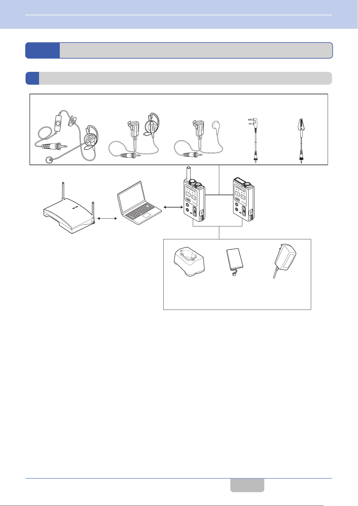
PTT
PTT
Clip Microphone with
Earphone EMC-13
Interface Cable
WD-RC50
Interface Cable
WD-RC100
Base Station
WD-K10BS
PC for System Setup
Portable Base
WD-K10PBS
Transceiver
WD-K10TR
Charger
KSC-48CR
Battery Pack
WD-UB110
WD-UB100
AC Adapter
KSC-44SL
Headset
KHS-37
Clip Microphone with
Earphone EMC-14
1 INTRODUCTION
1.7 System Configuration
1.7
System Configuration
System Configuration Diagram
Contents
7
Page 9

1 INTRODUCTION
1.7 System Configuration
System Configuration Table
No. Model Name Product Name Remarks
1 WD-K10PBS Portable Base It is a transceiver for wireless communication as a base unit or sub
unit of the DECT intercom system.
2 WD-K10TR Transceiver It is a transceiver that is the sub unit of the DECT intercom system. It
communicates wirelessly with the Portable Base or Base Station.
3 WD-K10BS Base Station It communicates with the transceiver.
4 KSC-48CR Charger A charger for the Portable Base WD-K10PBS/Transceiver WD-
K10TR.
5 KSC-44SL AC Adapter An AC adapter for the charger.
6 WD-UB110 Battery Pack A battery pack for the Portable Base WD-K10PBS.
7 WD-UB100 Battery Pack A battery pack for the Transceiver WD-K10TR.
8 EMC-13 Clip Microphone with
Earphone
9 EMC-14 Clip Microphone with
Earphone
10 KHS-37 Headset A headset for the Portable Base WD-K10PBS/Transceiver WD-
11 WD-RC100 Interface Cable
(Universal type)
12 WD-RC50 Interface Cable (2-Pin type) A conversion cable for the Portable base WD-K10PBS.
A clip microphone that is equipped with earphone.
A clip microphone that is equipped with earphone.
K10TR.
A conversion cable for the Portable base WD-K10PBS.
It is used when performing the PMR Link function.
It is used when performing the PMR Link function.
Contents
8
Page 10
PTT
PTT
PTT
PTT
P
TT
PTT
PTT
PTT
PTT
PTT
PTT
Blinking orange
WD-K10TR
Blinking green
WD-K10PBS
(Transceiver
Mode)
WD-K10PBS
(Base Station Mode)
1 INTRODUCTION
1.7 System Configuration
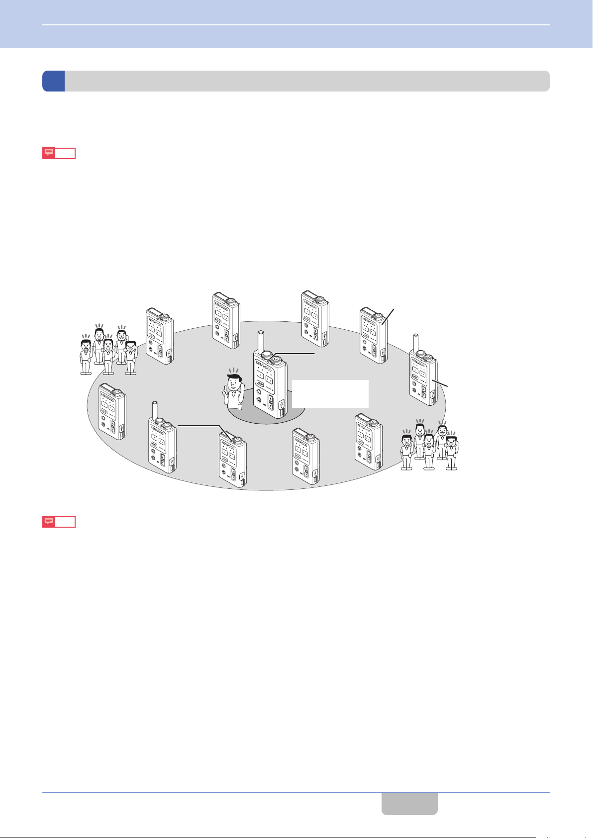
System Type
This product is a DECT intercom system that combines and uses both base and sub units.
The system may be of a portable or non-portable type, depending on the type of base unit.
Note
0
The base and sub units have already been configured for your system when you receive the transceiver. For details
on system configuration and setup, please consult the authorized dealer or installer.
Portable Type
Stand-alone
0
One Portable Base WD-K10PBS is operated as a base unit.
10 sub units can be connected at Normal Audio Quality using the Portable Base WD-K10PBS (Transceiver Mode) or
to
Up
the Transceiver WD-K10TR. Up to 5 sub units can be connected at High Audio Quality (including the base unit, maximum
11 units (or 6 units at High Audio Quality) can be used for simultaneous calls).
Note
0
To operate the Portable base as a sub unit, the mode on WD-K10PBS must be switched ( on page
0
You can use the system setup to change the quality mode from Normal Audio Quality to High Audio Quality for clearer
38).
and crispier calls. For details on the settings, please consult the authorized dealer or installer.
Contents
9
Page 11
PTT
PTT
PTT
PTT
PTT
PTT
PTT
PTT
PTT
PTT
WD-K10TR
WD-K10BS
Blinking orange
Blinking green
WD-K10PBS
(Transceiver
Mode)
1 INTRODUCTION
1.7 System Configuration
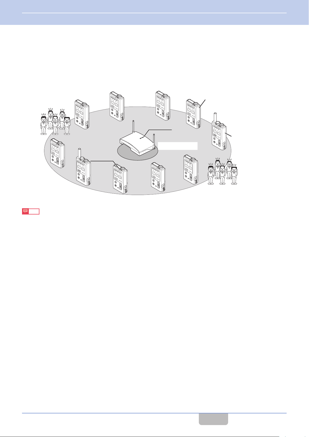
Non-Portable Type
Stand-alone
0
One Base Station WD-K10BS is operated as a base unit.
to
10 sub units can be connected at Normal Audio Quality using the Portable Base WD-K10PBS (Transceiver Mode) or
Up
the Transceiver WD-K10TR. Up to 5 sub units can be connected at High Audio Quality (a maximum of 10 units (or 5 units
at High Audio Quality) can be used for simultaneous calls).
Note
0
To operate the Portable base as a sub unit, the mode on WD-K10PBS must be switched ( on page
38).
Contents
10
Page 12
非常
音声警報
発報
火災 非火災
照明
表示切換
連動
連動一斉
非常復旧
発報連動停止
地震放送
停止
緊急優先
緊急優先
一斉
出力レベル
放送復旧
主電源
非常電源
緑色に点灯している時は正常、
赤色に点灯している時は
保守契約店にご連絡ください。
一斉
緊急
12
チャイム
日常点検
主回路/非常電源
目視
1.主回路/非常電源表示灯が緑色に点灯して
いること
2.充電中表示灯は点灯のこと
(蓄電池が正常に充電されていること)
操作
1.点検スイッチ1を3〜5秒間押す
電圧計がDC24〜29Vを示せば電池1は
正常
2.点検スイッチ2で蓄電池2を点検する
型式番号 EM-N112
製造年 年
蓄電池容量蓄電池1AH/5HR
蓄電池2AH/5HR
異常のある場合は保守契約店にご連絡ください
蓄電池1交換日
年 月 年 月
年 月 年 月
蓄電池2交換日
年 月 年 月
年 月 年 月
緑色の表示灯が点灯している時が正常、
赤色の表示灯が点灯している時は
保守契約店にご連絡ください
充電中蓄電池2点検蓄電池1
P
TT
PTT
PTT
PTT
PTT
PTT
PTT
P
TT
PT
T
P
TT
Blinking green
Blinking green
Blinking green
WD-K10BS
(Main Base Unit)
Blinking blue
WD-K10PBS
(Transceiver Mode)
WD-K10TR
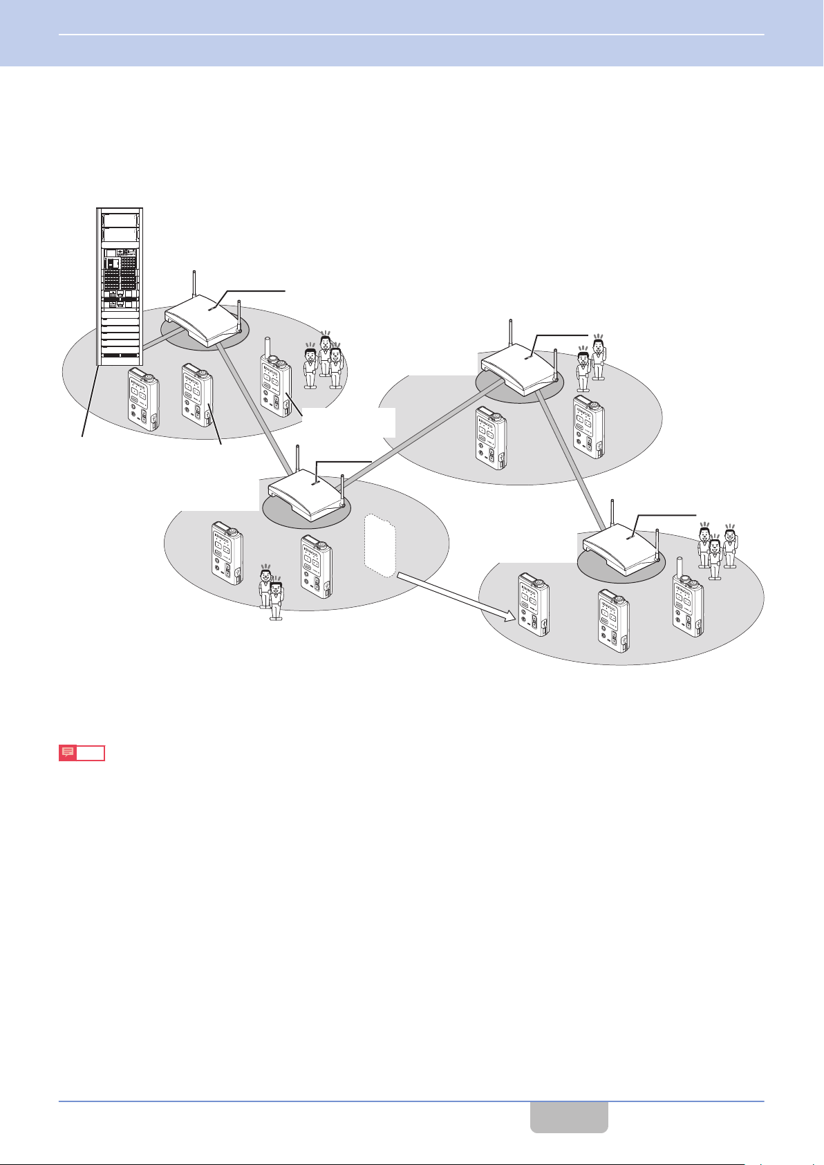
Emergency Broadcast
Systems
WD-K10BS
(Secondary Base Unit A)
Once it leaves the area,
auto cutoff occurs. It will
reconnect automatically to
the nearest base station.
WD-K10BS
(Secondary Base Unit B)
WD-K10BS
(Secondary Base Unit C)
1 INTRODUCTION
1.7 System Configuration
Baselink
0
For a non-portable type system, the area can be expanded by wiring multiple (maximum 4) base stations WD-K10BS.
One WD-K10BS is operated as a main base unit, and the rest (maximum 3 units) is operated as secondary base units.
main
The
base unit WD-K10BS can be connected to external devices. It allows intercom calls from the hall master and audio
signals from emergency broadcast systems to be heard over intercoms.
Note
0
It may take some time to switch base stations when the area is moved.
0
Connection is possible only if there is an empty channel at the base station of the moved destination.
0
The number of simultaneously connected units changes according to the surrounding radio wave condition, setup
condition, and environment.
0
Only the main base unit can be connected to external devices.
Contents
11
Page 13
J
K
L
M
N
C
D
E
F
G
I
H
N
A
B
J
K
L
M
N
C
D
E
F
G
I
H
N
1 INTRODUCTION
1.8 Part Names and Functions (Device Connection Method)
1.8
Note
0
For details on the connection method of the connecting jack of various devices, please consult the authorized dealer
or installer.
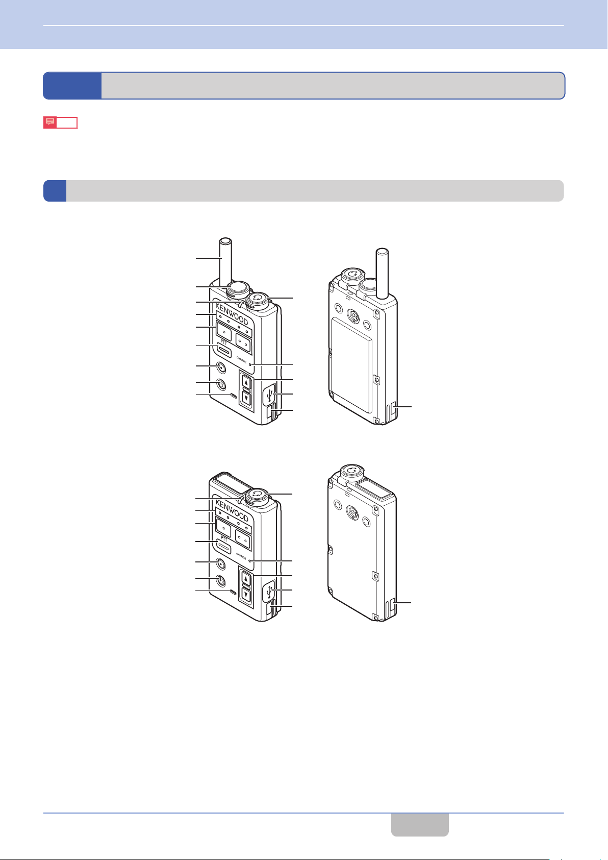
Part Names and Functions (Device Connection Method)
Portable Base WD-K10PBS/Transceiver WD-K10TR
WD-K10PBS
WD-K10TR
Contents
12
Page 14

1 INTRODUCTION
1.8 Part Names and Functions (Device Connection Method)
Antenna
A
PMR Link jack
B
For performing PMR Link. Single external wireless trigger jack.
Status LED
C
Indicates the status of the transceiver.
Indication
Blinking green (slow) ―
Blinking green (fast) ― Menu Setup
Green Wireless Sub Unit Registration Mode
Blinking red (slow) Low battery
Blinking red (fast) Very low battery
Red Power ON
Blinking blue (slow) ― Listening Mode
Blinking blue (fast) System error
Blue Wireless setting by the PC
Blinking orange
(slow)
Blinking orange (fast) Menu Setup ―
Blinking green and
orange alternately
Blinking (slow): Blinks every 3 seconds
0
Blinking (fast): Blinks every 1 second
Precautions
When the Status LED blinks rapidly in blue and a system error appears, check that the plug of the clip microphone is
0
firmly inserted into the Portable base WD-K10PBS/Transceiver WD-K10TR. Then turn on/off the power to reset. If the
unit still does not recover, please consult the authorized dealer or installer.
Base Station Mode Transceiver Mode
Normal Mode ―
Updating Updating
Status
Normal Mode/
Listening Talk
Power ON/No line connection
(Out of range, call disabled)
Group LED
D
Indicates the current call group.
[PF 1] key/[PF 2] key
E
Press or press and hold to execute the function configured to each key.
function
Any
0
For details, please consult the authorized dealer or installer.
[PTT] key
F
Press to make a call.
Depending on the setting, this key is disabled when a clip microphone or headset microphone adapter which is sold
0
separately is connected. For details, please consult the authorized dealer or installer.
[All Call] key
G
Press and hold to make an All Call.
Any function can be configured to the [All Call] key. The transceiver may come with different function for each key.
0
For details, please consult the authorized dealer or installer.
can be configured to each key. The transceiver may come with different name and function for each key.
Contents
13
Page 15

1 INTRODUCTION
1.8 Part Names and Functions (Device Connection Method)
Power key
H
Press and hold to turn the power on/off. Press to check the remaining capacity in the battery. The battery charge LED
blinks.
Microphone
I
When making a call with the transceiver without using the clip microphone, speak into this microphone.
This key is disabled when a clip microphone or headset microphone adapter which is sold separately is connected.
0
Microphone/ Earphone jack
J
For connecting a clip microphone, earphone or headset microphone adapter which is sold separately. Do not connect
any device other than the compatible models.
Battery Charge LED
K
Indicates the charging status.
Light up
Blinking
Light goes off : Charging complete
: Charging in progress
: Charging in preparation, or charging error
L
[J]/[K] key
For adjusting the receiver volume level. The receiver volume changes with each press of the J/K key, from level 1 to
15. For details, refer to “Adjusting the Receiver Volume Level” ( on page 39).
Data setting connector
M
For registering the transceiver to the system or changing the settings.
Normally not used. Do not open the cover. And do not touch the connector.
0
Charge contact terminal
N
Contents
14
Page 16
A
B
C
D
E
FRONT
REAR
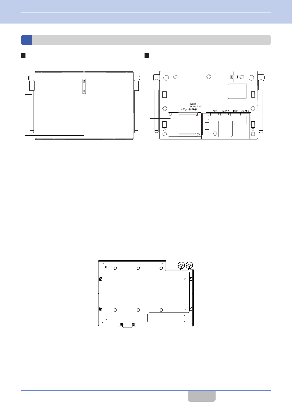
1 INTRODUCTION
1.8 Part Names and Functions (Device Connection Method)
Base Station WD-K10BS
Status LED
A
Indicates the status of the base station with the LED color.
Antenna
B
For registering sub units to the base station through wireless communication.
[Registration] key
C
Cover (DC plug area)
D
Remove the cover when connecting the AC adapter to the DC IN jack or when the data setting connector and baselink
terminal block are used.
Packing (Setting/ adjust area)
E
Remove this when connecting external audio equipment, adjusting volume, or using the Mode select switch.
Mounting Plate
For use when installing the base station to the wall or ceiling.
Contents
15
Page 17
F
G
H
Packing for
DC plug area
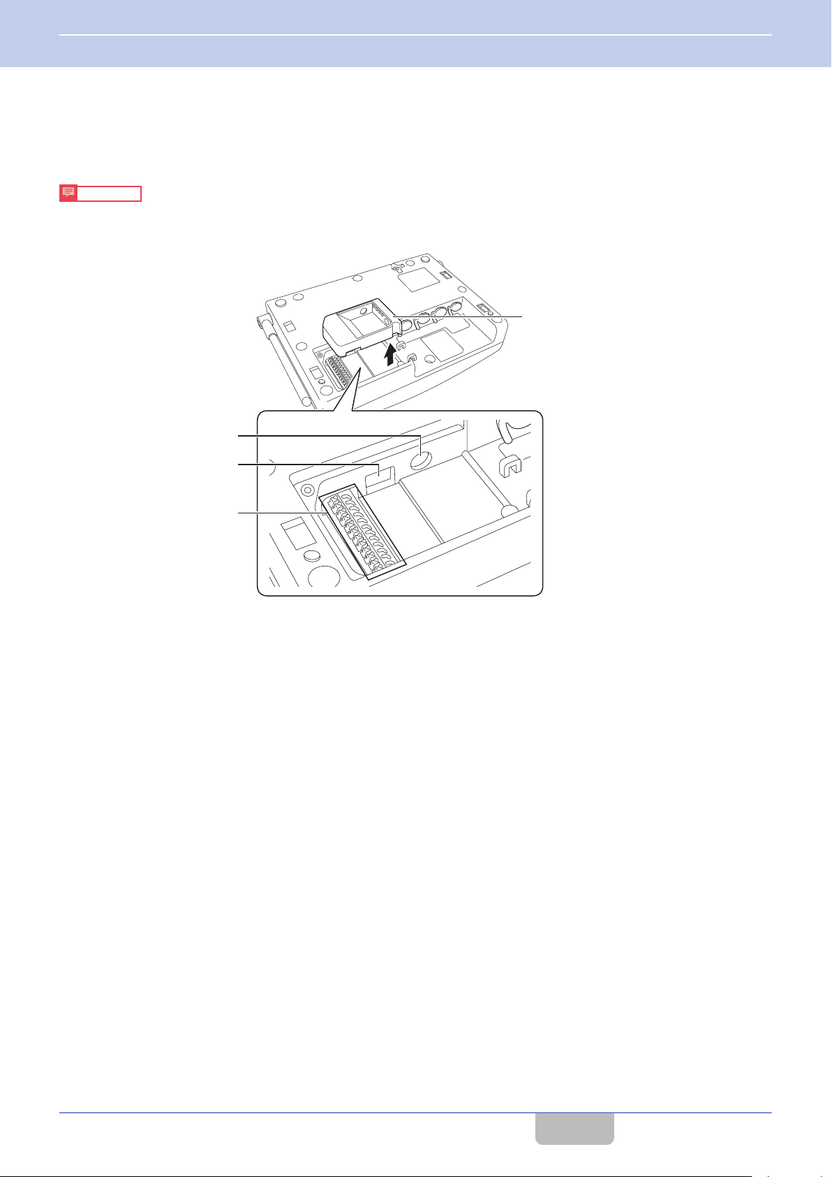
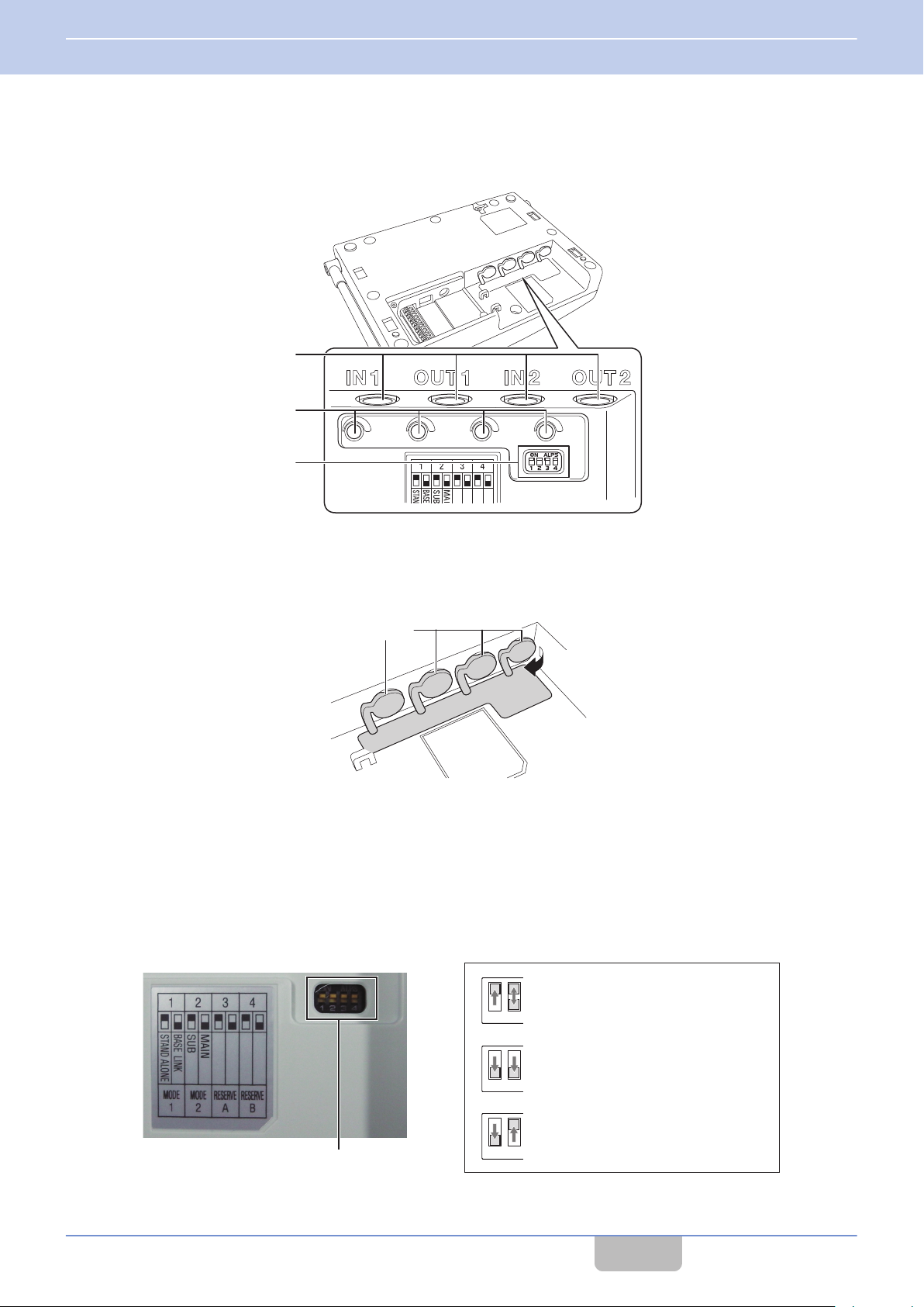
1 INTRODUCTION
1.8 Part Names and Functions (Device Connection Method)
Underneath the Cover (DC Plug Area)
There is a packing for the DC plug area underneath the cover (DC plug area). Remove the packing to use the DC IN jack,
Data setting connector and Baselink/ External Control terminal block.
Precautions
When the DC plug is dirty, noise may occur during conversation. Wipe with a dry cloth regularly.
0
Be sure to connect or disconnect the DC plug only when the power is turned off.
0
DC IN jack
F
For connecting the DC plug of the AC adapter.
Data setting connector
G
For registering the base station to the system or changing the settings using the Programming Software.
Normally not used. Do not touch the connector.
Contents
16
Page 18
K
Main Base Unit
Secondary Base Unit A Secondary Base Unit B
Wiring cable (no polarity) Wiring cable (no polarity)
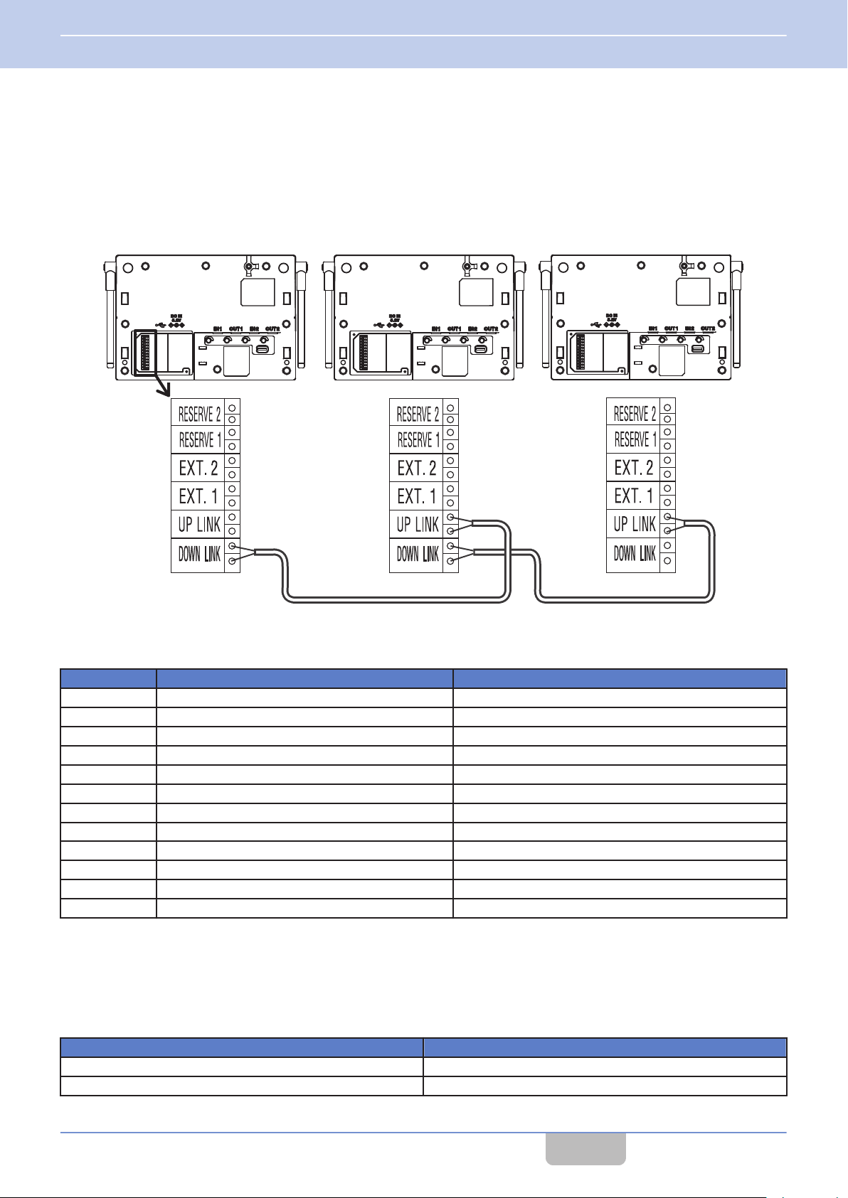
1 INTRODUCTION
1.8 Part Names and Functions (Device Connection Method)
Baselink/ External Control terminal
H
For operating the base station as the Baselink system or controlling an external device.
When operating in Baselink system, change the settings with the
the baselink control terminal blocks of the base units with a wiring cable.
Connection example: Connecting base units in a Baselink system
Mode select switch ( on page 18
), and connect
WD-K10BS Baselink/External Control terminal
DOWN LINK Baselink Down-Link No polarity
DOWN LINK Baselink Down-Link No polarity
UP LINK Baselink Up-Link No polarity
UP LINK Baselink Up-Link No polarity
EXT.1 External Control 1 Contact output a No polarity Max. 24 V/1 A
EXT.1 External Control 1 Contact output a No polarity Max. 24 V/1 A
EXT.2 External Control 2 Contact output a No polarity Max. 24 V/1 A
EXT.2 External Control 2 Contact output a No polarity Max. 24 V/1 A
RESERVE 1 NC Spare terminal
RESERVE 1 NC Spare terminal
RESERVE 2 NC Spare terminal
RESERVE 2 NC Spare terminal
Conditions for wiring cable
0
Use a UTP cable (unshielded twisted pair cable) with a characteristic impedance of 100
of 1 MHz or above as the connecting cable between the base stations for communication.
Fuji Electric Cable Co., Ltd. “Electronic button telephone digital transmission cable ICT”
Maximum wiring distance
Wire Diameter (mm) Wiring Distance (m)
φ 0.5 600
φ 0.65 1000
Name Description
Ω at a maximum frequency band
Contents
17
Page 19
K
I
J
Packing
Pull out
1234
1234
1234
Mode select switch
Stand-alone system base unit
The unit operates as a stand-alone
system when either of MAIN/SUB
(SW2) is selected.
Baselink
Main Base Unit
Baselink
Secondary Base Unit
1 INTRODUCTION
1.8 Part Names and Functions (Device Connection Method)
Underneath the Packing (Setting/ Adjust Area)
There is an Ext Audio input/output jack, a volume adjust knob and a Mode select switch underneath the packing.
Ext Audio input/output jacks (2 lines)
I
calls
Group
WT-MC60 or external device allows users to participate in group calls.
Pull out the jack packing when connecting an external device.
To maintain the waterproof performance, cover the jacks with the packing when not in use.
Volume adjust knob
J
For adjusting
for the adjustment.
Mode select switch
K
For configuring the device type and operation mode of the base station.
can be output externally by connecting this unit to an external audio equipment. Connecting to a hall master
the volume of the external audio equipment or microphone connected. A flat-blade screwdriver is required
Contents
18
Page 20
1 INTRODUCTION
1.8 Part Names and Functions (Device Connection Method)
Status LED Indication
Operation Mode
Indication
Blinking green (slow) ― ― Normal Mode
Green
Blinking red (slow) Power ON
Blinking blue (slow) ― Normal Mode ―
Blinking blue (fast) System error
Blue Wireless setting by the PC
Blinking orange (slow) Normal Mode ― ―
Blinking green and
orange alternately
Wireless Sub Unit Registration
Stand-alone
Base Unit
Mode
Baselink
Main Base Unit
Wireless Sub Unit Registration
Mode ―
Updating
Baselink
Secondary Base Unit
Power ON, No line connection
(Out of range, call disabled)
Blinking (slow): Blinks every 3 seconds
Blinking (fast): Blinks every 1 second
Precautions
When the Status LED blinks rapidly in blue and a system error appears, check that the plug of the clip microphone is
0
firmly inserted into the Portable Base WD-K10PBS or Transceiver WD-K10TR. Then turn on/off the power to reset.
If the unit still does not recover, please consult the dealer.
Contents
19
Page 21
A
B
C
D
1 INTRODUCTION
1.8 Part Names and Functions (Device Connection Method)
Charger KSC-48CR
The charger KSC-48CR can be combined and used with the separately available AC adapter KSC-44SL or KSC-44ML.
Top
Transceiver charging slot
A
Charging port for inserting the transceiver to be charged.
Charging terminal
B
Bottom
Connecting bracket
C
For connecting multiple (maximum 6) chargers.
For details on how to connect chargers, please refer to the instruction manual of Charger KSC-48CR.
DC IN jack
D
For inserting the DC plug of the AC adapter.
Contents
20
Page 22
A
B
C
D
E
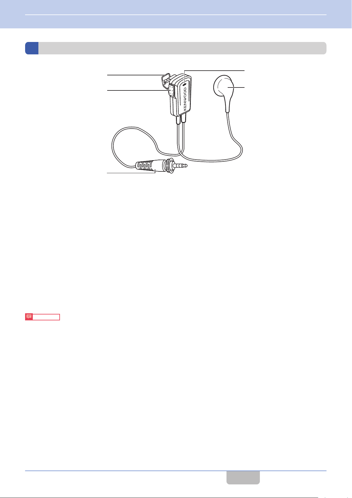
1 INTRODUCTION
1.8 Part Names and Functions (Device Connection Method)
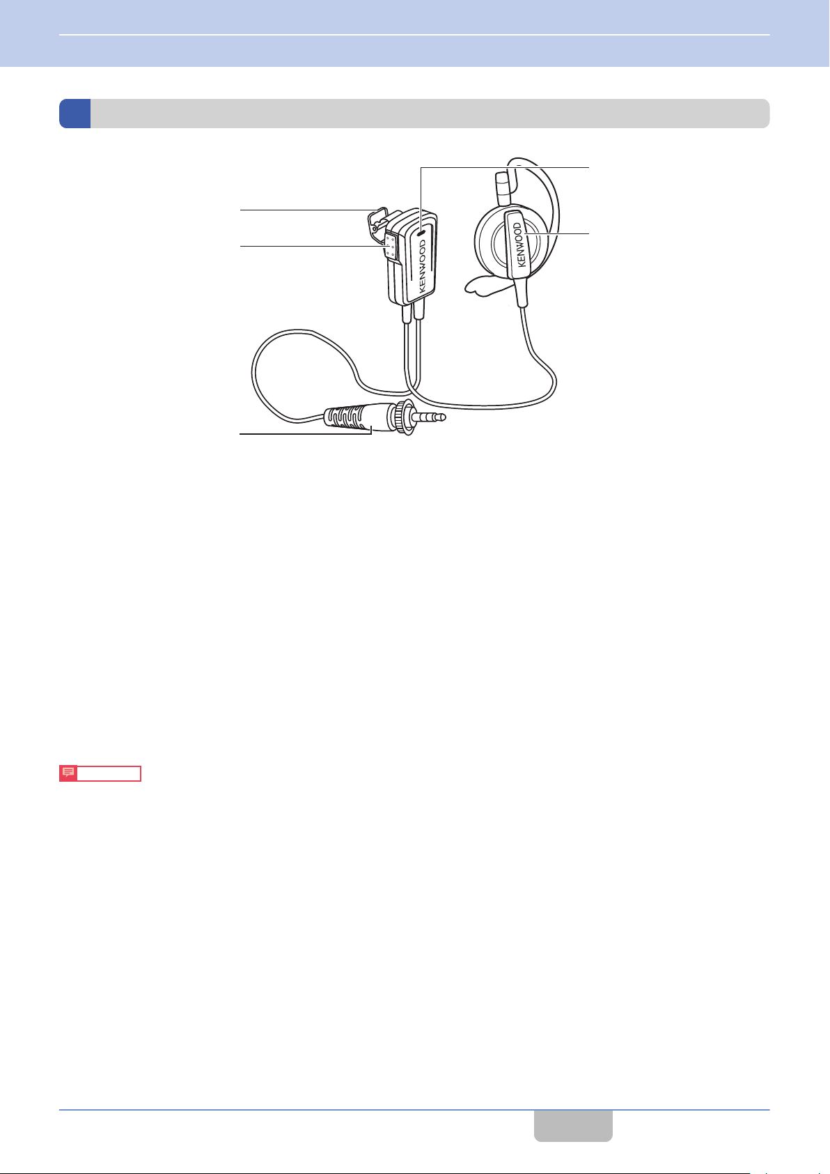
Clip Microphone with Earphone EMC-13
Microphone clip
A
Use this to attach to the collar of your clothes.
[PTT]
B
C
D
E
Insert firmly
0
connection with the transceiver and noise may occur. Note that this is not water resistant.
When the plug is dirty, noise may occur during conversation. Wipe with a dry cloth regularly.
0
Be sure to connect or disconnect the plug only when the power is turned off.
0
key
Press this key for business contact as an intercom.
Transceiver connection plug
For connecting to an appropriate transceiver.
Microphone
The microphone is a close-talking type microphone. To speak, place your mouth close to the microphone. (5 cm)
Earphone
Insert into your ear to listen to the conversation.
Precautions
into the terminal so that the plug does not come off, and tighten the cap. If the cap is not fully tightened, poor
Contents
21
Page 23
A
B
C
D
E
1 INTRODUCTION
1.8 Part Names and Functions (Device Connection Method)
Clip Microphone with Earphone EMC-14
Microphone clip
A
Use this to attach to the collar of your clothes.
[PTT]
B
C
D
E
Insert firmly
0
connection with the transceiver and noise may occur. Note that this is not water resistant.
When the plug is dirty, noise may occur during conversation. Wipe with a dry cloth regularly.
0
Be sure to connect or disconnect the plug only when the power is turned off.
0
key
Press this key for business contact as an intercom.
Transceiver connection plug
For connecting to an appropriate transceiver.
Microphone
The microphone is a close-talking type microphone. To speak, place your mouth close to the microphone. (5 cm)
Earphone
Insert into your ear to listen to the conversation.
Precautions
into the terminal so that the plug does not come off, and tighten the cap. If the cap is not fully tightened, poor
Contents
22
Page 24

A
B
C
D
E
1 INTRODUCTION
1.8 Part Names and Functions (Device Connection Method)
Headset KHS-37
Microphone clip with [PTT] key
A
Press this key for business contact as an intercom.
Transceiver connection plug
B
For connecting to an appropriate transceiver.
Microphone
C
To speak, adjust the boom microphone such that it is about 1 cm away from your mouth.
The boom microphone can be moved up and down.
Cord clip
D
Use this to clip the cord to the collar of your clothes when it gets in the way.
Earphone
E
Insert into your ear to listen to the conversation.
Precautions
Insert firmly
0
connection with the transceiver and noise may occur. Note that this is not water resistant.
When the plug is dirty, noise may occur during conversation. Wipe with a dry cloth regularly.
0
Be sure to connect or disconnect the plug only when the power is turned off.
0
into the terminal so that the plug does not come off, and tighten the cap. If the cap is not fully tightened, poor
Contents
23
Page 25

A
B
C
1 INTRODUCTION
1.8 Part Names and Functions (Device Connection Method)
Interface Cable WD-RC50
The transceiver connection cable WD-RC50 is a conversion cable for communication between the DECT intercom system
WD-K10 series and external wireless system (KENWOOD brand). (For 2-pin connector)
It is used to connect to the Portable base WD-K10PBS.
PMR Link jack
A
Connect to the 2-pin connector of the two-way radios of the KENWOOD in an external wireless system.
Cap
B
After connecting to the transceiver, turn the cap and secure.
Transceiver connection plug
C
For connecting to an appropriate transceiver.
Precautions
Insert firmly
0
connection with the transceiver and noise may occur. Note that this is not water resistant.
When the plug is dirty, noise may occur during conversation. Wipe with a dry cloth regularly.
0
Be sure to connect or disconnect the plug only when the power is turned off.
0
into the terminal so that the plug does not come off, and tighten the cap. If the cap is not fully tightened, poor
Contents
24
Page 26

A
B
C
1 INTRODUCTION
1.8 Part Names and Functions (Device Connection Method)
Interface Cable WD-RC100
The transceiver connection cable WD-RC100 is a conversion cable for communication between the DECT intercom system
WD-K10 series and external wireless system (KENWOOD brand). (For universal connector)
It is used to connect to the Portable base WD-K10PBS.
PMR Link jack
A
Connect to the universal connector of the two-way radios of the KENWOOD in an external wireless system.
Cap
B
After connecting to the transceiver, turn the cap and secure.
Transceiver connection plug
C
For connecting to an appropriate transceiver.
Precautions
Insert firmly
0
connection with the transceiver and noise may occur. Note that this is not water resistant.
When the plug is dirty, noise may occur during conversation. Wipe with a dry cloth regularly.
0
Be sure to connect or disconnect the plug only when the power is turned off.
0
into the terminal so that the plug does not come off, and tighten the cap. If the cap is not fully tightened, poor
Contents
25
Page 27

2
Connector
Connector
PREPARATION
2.1
Replacing the Battery Pack
This transceiver comes with the battery pack already installed in it. To replace the battery pack, follow the steps below to
remove and install the battery pack.
Remove the screws (x6) on the rear of the transceiver and remove the rear cover.
1
Preparing the Device
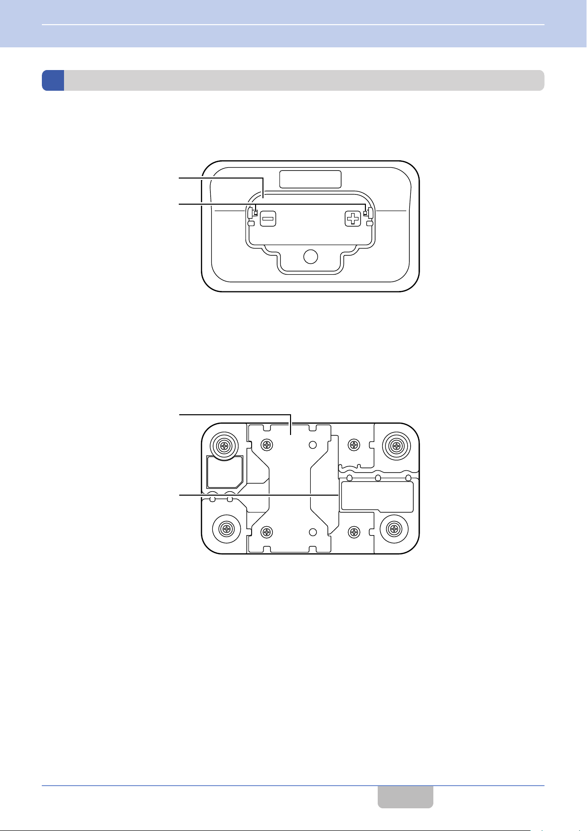
Take out the battery pack and remove the battery connector.
2
When removing the connector, hold the base of the connector and pull it straight up slowly.
Connect the battery connector to the connector of the transceiver unit.
3
Contents
26
Page 28

Catch
Catch
Catch
2 PREPARATION
2.1 Preparing the Device
Arrange the battery cable as shown in the illustration and push in the battery.
4
Push in firmly until the catches are sitting on the battery pack.
Attach the rear cover to the transceiver unit and tighten the screws (x6).
5
After installing the battery pack, attach the rear cover and secure it by tightening the screws.
Precautions
When attaching the rear cover, ensure that no fine foreign material (including fiber, hair and sand) is caught in
0
between, so as to maintain the dust resistant/water resistant performance.
To maintain the water resistant performance, please check with the authorized dealer.
Contents
27
Page 29

Groove
In this illustration, the cable is inserted in the left groove.
ToACOUTLE
T
AC Adapter
(KSC-44SL)
Charger
(KSC-48CR)
Transceiver
(WD-K10PBS / WD-K10TR)
2 PREPARATION
2.1 Preparing the Device
Charging the Battery Pack
Be sure to charge the transceiver using the charger KSC-48CR before using.
Remove the bracket underneath the charger and insert the DC plug of the AC adapter into the DC IN jack
1
of the charger.
For details on installing and removing the bracket, refer to the instruction manual of the charger KSC-48CR.
Insert the cable of the AC adapter into the left or right groove depending on where the charger is set up.
2
Reinstall the bracket and insert the AC adapter into the AC outlet.
3
Place the transceiver with the battery pack installed onto the charger.
4
The battery charge LED lights up in red and charging begins.
0
The transceiver turns off automatically if it is placed on the charger while it is turned on. For safety purpose, turn
0
off the transceiver during charging.
Check that the metal terminals of the transceiver are in firm contact with the terminals on the charger.
0
The battery charge LED goes off when charging is complete. Take out the transceiver.
0
The estimated time required to complete the charging is as follows:
0
WD-K10PBS: Approx. 6 hours
WD-K10TR: Approx. 5 hours
Precautions
Be sure to use the specified charger WD-C100CR to charge WD-K10PBS and WD-K10TR.
0
Contents
28
Page 30

The screws can become loose.
Tighten again periodically.
Screws (supplied)
Belt clip
2 PREPARATION
2.1 Preparing the Device
Attaching the Belt Clip
The transceiver can be attached to a belt using the supplied belt clip.
Connecting the Clip Microphone
Use a clip microphone (sold separately) for clearer calls even under a noisy environment.
Insert the connecting plug into the connecting jack of the transceiver, and secure by turning the cap in the
1
direction of the arrow.
Note
0
Be sure to read the instruction manual of the connecting device before using.
0
Make
on activates the protector which disables operation on the transceiver. The clip microphone or headset microphone
adapter is also disabled.
0
For information on supported accessories of the clip microphone or headset microphone adapter, please refer to the
DECT intercom system WD-K10 series website.
http://manual.kenwood.com/en_contents/search/keyword
to turn off the transceiver before making a connection. Making a connection while the transceiver is turned
sure
Contents
29
Page 31

2 PREPARATION
2.1 Preparing the Device
Connecting the Transceiver Connection Cable
Connect the transceiver connection cable WD-RC100 or WD-RC50 to allow communication between the DECT intercom
system WD-K10 series and external wireless systems (KENWOOD brand).
Compatible models:
0
of the KENWOOD brand that can be connected to the transceiver connection cable WD-RC100 or WD-
Two-way
RC50 are as follows:
WD-RC100: NX-200G, NX-300G, NX-5200, NX-5300
WD-RC50: NX-220, NX-320, TK-2000, TK-3000, TK-2302, TK-3302, TK-3401D, TK-3501
Precautions
As far as possible, use the transceiver and portable base at a distance away from external wireless systems.
0
An error due to radio wave interference may occur if they are too near.
Do not connect any two-way radios other than the compatible models.
0
To communicate with external wireless systems, the “PMR Link” function must first be assigned.
0
For details on assigning the function, please consult the authorized dealer or installer.
radios
Connecting to a Portable base WD-K10PBS
Insert the connecting plug into the connecting jack of the transceiver, and secure by turning the cap in the direction of the
arrow.
Contents
30
Page 32

2 PREPARATION
2.1 Preparing the Device
Connecting to an External Wireless System Transceiver
Insert the guide of the transceiver connection cable into the groove of the transceiver, and secure tightly with screws. The
screws can be tightened by hand but in order to ensure water resistance, use a coin screwdriver to tighten or remove.
Precautions
When using two-way radio, do not use or place it on the charger. Be sure to remove it from the charger.
0
Note
0
Make sure to turn off the external transceiver before making a connection.
Contents
31
Page 33

ToACOUTLE
T
2 PREPARATION
2.2 Turning On/Off the Device Power
2.2
Turning On/Off the Device Power
Turning On/Off the Power of WD-K10BS
Turning on the Power
Plug the AC adapter of WD-K10BS into the AC outlet to turn on.
Turning off the Power
Unplug the AC adapter of WD-K10BS from the AC outlet to turn off the power.
Contents
32
Page 34

Group LED
Status LED
Battery Charge LED
[Power] key
[Power] key
2 PREPARATION
2.2 Turning On/Off the Device Power
Turning On/Off the Power of WD-K10PBS / WD-K10TR
Turning on the Power
Hold down the [Power] key.
1
up and then light off.
Base Station Mode
0
When the unit is linked to the system, the Status LED blinks in orange. Group LEDs of the connected group light up for a few
seconds and then blink. Voice announcement for the connected group is being played and the unit enters Group Call Mode.
Transceiver Mode
0
When the unit is linked to the system, the Status LED blinks in green. Group LEDs of the connected group light up for a few
seconds and then blink. Voice announcement for the connected group is being played and the unit enters Group Call Mode.
Release
after the Status LED (red), Group LEDs, and Battery Charge LED light
When the unit is unable to link to the system, the Status LED lights up in red. Move to a location where linking is possible.
Turning off the Power
Hold down the [Power] key until the Status LED lights off.
1
Check that the LED lights off and is not blinking.
Contents
33
Page 35

PTT
PTT
Or
Base Unit
Sub Unit
Register side by side
2 PREPARATION
2.3 Registering the Device
2.3
Registering the Device
Registering Sub Unit to Base Unit
This system is used when the transceiver to be used as a sub unit is registered to the Portable base WD-K10PBS or Base
station WD-K10BS that is to be used as the base unit.
Precautions
108 sub units can be registered to one base unit. Registration may fail if you try to register more than the maximum
Up to
0
number of sub units to a base unit.
Note
0
The Portable base WD-K10PBS (Transceiver Mode only) or Transceiver WD-K10TR can be registered as a sub unit.
0
Perform registration for each device one at a time.
Contents
34
Page 36

Group LED
Status LED
[All Call] key
[Power] key
2 PREPARATION
2.3 Registering the Device
Registering Sub Unit to WD-K10PBS (Base Station Mode)
Note
0
For details
page 38.
Turn off the base unit and sub unit if they have been turned on.
1
Press and hold the [Power] key until the Status LED goes off to turn off the power.
Start the base unit in registration mode.
2
While pressing the [All Call] key of the base unit, press and hold the [Power] key until the Status LED lights up in
green and all the Group LEDs are blinking.
The sub unit enters into registration mode.
on how to switch WD-K10PBS to Transceiver Mode, refer to Starting WD-K10PBS in Transceiver Mode on
3
Start the sub unit in registration mode.
While pressing the [All Call] key of the sub unit, press and hold the [Power] key until the Status LED lights up in green
and all the Group LEDs are blinking.
The sub unit enters into registration mode.
The registration begins automatically when both the base unit and sub unit are in registration mode.
When registration is successful:
The Status LED of the sub unit lights up in green and all the Group LEDs light up.
When registration has failed:
The Status LED of the sub unit lights up in green but all the Group LEDs do not light up. Restart the units in
registration mode and register again.
All sub units are registered to the same group (Group A) by default.
0
Contents
35
Page 37

Status LED
[Registration]
key
2 PREPARATION
2.3 Registering the Device
Restart the sub unit.
4
When registration of sub unit is successful, restart the sub unit.
After the registration is complete, turn on the power of the base unit and restart as well.
Note
0
To exit registration mode, press and hold the [PF 2] key.
0
If registration fails repeatedly, the maximum number of registrations may have been exceeded.
Registering Sub Unit to WD-K10BS
Note
0
A sub unit cannot be registered to a secondary base unit for a Baselink system. Register it to the main base unit.
Turn off the sub unit if it has been turned on.
1
To turn off the sub unit, press and hold the [Power] key until the Status LED goes off.
Turn on WD-K10BS.
2
Plug the AC adapter of WD-K10BS into the AC outlet to turn on.
Press and hold the [Registration] key until the Status LED lights up in green.
3
The sub unit enters into registration mode.
Contents
36
Page 38

Group LED
Status LED
[Power] key
[All Call] key
2 PREPARATION
2.3 Registering the Device
Start the sub unit in registration mode.
4
While pressing the [All Call] key of the sub unit, press and hold the [Registration] key until the Status LED lights up
in green and all the Group LEDs are blinking.
The sub unit enters into registration mode.
The registration begins automatically when both the base unit and sub unit are in registration mode.
When registration is successful:
The Status LED of the sub unit lights up in green and all the Group LEDs light up.
When registration has failed:
The Status LED of the sub unit lights up in green but all the Group LEDs do not light up. Restart the units in
registration mode and register again.
All sub units are registered to the same group (Group A) by default.
0
Restart the sub unit.
5
When registration of sub unit is successful, restart the sub unit.
After registration is complete, exit registration mode by pressing and holding the [
Note
0
If registration fails repeatedly, the maximum number of registrations may have been exceeded.
Registration] key on WD-K10BS.
Contents
37
Page 39

Group LED
Status LED
[Power] key
[PF 1] key
2 PREPARATION
2.3 Registering the Device
Starting WD-K10PBS in Transceiver Mode
WD-K10PBS can be used as a base unit or sub unit.
To use as a sub unit, perform the following operations and start in Transceiver Mode.
Precautions
The mode in WD-K10PBS has been configured to your system in advance. Unless it is necessary, do not change the
0
startup mode. For details on the settings, please consult the authorized dealer or installer.
If the unit is turned on, turn off the power by pressing and holding the [Power] key until the Status LED
1
goes off.
While pressing the [PF 1] key, turn on the power by pressing and holding the [Power] key.
2
For turning on the power, refer to Turning on the Power on page 33
The unit enters into Transceiver Mode. Voice announcement for the activation of Transceiver Mode is being played
and the Status LED blinks in green.
The following table shows the Status LED indication and voice announcement during the activation of Transceiver
Mode and Base Station Mode.
Startup Mode LED Indication Voice Announcement during Mode Activation
Base Station Mode Blinking orange Base Station
Transceiver Mode Blinking green Transceiver
.
Note
0
Once the unit is start in Transceiver Mode, it will start in Transceiver Mode the next time simply by turning on
the power.
0
Performing the same operations when in Transceiver Mode (sub unit) changes the unit to Base Station Mode
(base unit).
0
The voice announcement may not be played depending on the transceiver settings. (
Contents
on page
47)
38
Page 40

2 PREPARATION
2.4 Setting Various Functions
2.4
Setting Various Functions
Adjusting the Receiver Volume Level
Use the [J]/[K] key to adjust to an appropriate volume level.
Use the [J] key to increase the current volume level by 1.
Use the [K] key to lower the current volume level by 1.
Note
0
Pressing and holding the [J]/[K] key does not adjust the volume continuously.
0
you
try to increase or decrease the volume when it is already at its maximum or minimum, a notification tone is emitted.
If
Lowering the volume level temporarily (Volume attenuation)
0
Press and hold the [K] key.
1
The volume level decreases to the value configured.
Pressing the [J] key during volume attenuation cancels the volume attenuation and restores the original volume
0
level.
Contents
39
Page 41

Group LED
Status LED
[Power] key
2 PREPARATION
2.4 Setting Various Functions
Checking Battery Remaining Capacity
You can check the current battery remaining capacity.
Press the [Power] key.
1
A voice announcement according to the battery remaining capacity is being played. The battery charge LED will
display the remaining capacity for 4 seconds.
Remaining Capacity in the Battery Battery Charge LED Voice Announcement
30% or more Blinks 3 times Battery high
10% or more to less than 30% Blinks 2 times Battery middle
Less than 10% Blinks 1 time Battery low
Note
0
When the
emitted at every 10-second interval. Please charge the battery.
0
The voice announcement may not be played depending on the transceiver settings. ( on page 47)
remaining capacity in the battery is low, the Status LED blinks in red and the battery warning tone is
Contents
40
Page 42

Status LED
[Power] key
2 PREPARATION
2.4 Setting Various Functions
Configuring in Setup Menu Mode
Start the transceiver in Setup menu mode to configure various functions.
If the unit is turned on, turn off the power by pressing and holding the [Power] key until the Status LED
1
goes off.
While pressing the [PTT] key, turn on the power by pressing and holding the [Power]
2
For WD-K10PBS, press until the Status LED blinks in orange.
For WD-K10TR, press until the Status LED blinks in green.
The Setup menu mode is activated.
After the voice announcement for the activation of the Setup menu mode is played, a voice announcement for the
initial setup items will be played.
key.
Press the [J], [K] key and select an item to configure.
3
A voice announcement will be played for the item name every time an item is switched.
Contents
41
Page 43

2 PREPARATION
2.4 Setting Various Functions
Press the [PTT] key and confirm a setup item.
4
Press the [J], [K] key and select a setting.
5
A voice announcement will be played for the setting details every time a setting is switched. To return to selecting a
setup item, press the [PF 1] key.
Press the [PTT] key to confirm a setting.
6
Press and hold the [PF 2] key.
7
Save the setting. Restart the transceiver and return to Group Call Mode.
Settings in setup menu mode
0
*: Default setting
Item
(Voice Announcement)
Base Station Select
(Base Select)
Talk Setting
(Talk Setting)
VOX Sensitivity
(VOX Level)
Mic Gain
(Mic Gain)
Settings Content
Auto*/Base 1/Base 2/Base
3/Base 4/Base 5/Base 6
PTT*/PTT-Lock/VOX Switches the operation of the [PTT] key.
Level 1 - Level 5
(3*)
Level 1 - Level 5
(3*)
Switches the base unit (Portable base or Base station) to
be connected.
If “Auto” is selected, the base station to be connected will
be automatically selected.
* PTT:
You can
or the clip microphone is being pressed.
* PTT-Lock:
Press the [PTT] key on this transceiver or the clip
microphone to call. Press it again to end the call. If “PTTLock Delay”is configured, the call ends automatically when
the duration configured elapses.
* VOX:
The microphone automatically turns ON in response to
audio signals. Hands-free call is possible without having to
press the [PTT] key.
Sets the sensitivity when the Talk Setting is set to “VOX”.
Adjusts the input sensitivity of the microphone.
make a call while the [PTT] key on this transceiver
Contents
42
Page 44

2 PREPARATION
2.4 Setting Various Functions
Setting Key Lock On/Off
Lock the function keys and All Call key of the transceiver to prevent the keys from being operated.
Precautions
0
This
function
cannot be executed by default. For details on the settings, please consult the authorized dealer or installer.
Setting Key Lock On
Key operation during key lock is disabled. Notification tones and voice announcement will not be played as well.
While pressing the [J] key, press and hold the [K] key.
1
The Key Lock tone will be emitted and the keys will be locked.
Setting Key Lock Off
While pressing the [J] key during Key Lock, press and hold the [K] key.
1
The Key Lock Off tone will be emitted and the keys will be unlocked.
Contents
43
Page 45

Switch Talk Function
2 PREPARATION
2.4 Setting Various Functions
Changing the PTT Key Setting
“PTT”, “PTT-Lock”, or “VOX” can be selected for the Talk Setting.
Precautions
The [Switch Talk Function] key is not assigned by default. Assign the function to any function keys.
0
To configure the setting, consult the authorized dealer or installer.
Note
0
The Talk
menu mode)” ( on page 41).
Setting can be changed using the “Setup menu mode”. For details, refer to “Setting Various Functions (Setup
Press the [Switch Talk Function]
1
The unit functions in the setting as configured in Talk Setting. The Talk Setting after the change will be played back
in a voice announcement.
Press the [Switch Talk Function] key again to return to the original talk operation.
key.
Contents
44
Page 46

Manual Reconnection
Status LED
2 PREPARATION
2.4 Setting Various Functions
Manual Reconnection (Transceiver Mode Only)
Reconnect regardless of the radio wave status.
Precautions
The [Manual Reconnection
0
For details on the settings, please consult the authorized dealer or installer.
Press the [Manual Reconnection] key.
1
Current connection with the base unit (Portable base or Base station) will be cut off.
The Status LED lights up in red.
key is not assigned by default. Assign the function to any function keys.
]
Once the unit is reconnected to the base unit, a voice announcement will be played and the Status LED blinks in
green.
Note
0
The voice announcement may not be played depending on the transceiver settings. ( on page
47)
Contents
45
Page 47

2 PREPARATION
2.4 Setting Various Functions
Notification Tones During the Use of Transceiver
Depending on the selected mode and status, you can hear the notification tones of the transceiver from earphones.
The following table shows the name and content of various notification tones.
Name Status
Alert tone Invalid key operation. When the operation mode of the transceiver did not
change. Already in the mode.
Key Operation tone When a key is pressed.
Out of Range Tone The [PTT] key is pressed when the user moves to a location with weak radio
signals or when there are no empty channels in the base station.
Battery Warning
(10-second interval)
Battery Warning Alert tone
(5-second interval)
Error When there is an abnormality in the battery.
Listening Talk switch tone When a sub unit in Listening Mode has switched to a transmission mode.
Listening Talk migration tone When a sub unit in Listening Mode has switched to a call transmission mode.
Volume Change tone When the volume has changed
Maximum volume notification tone When you try to increase the volume when it is already at its maximum.
Minimum volume notification tone When you try to decrease the volume when it is already at its minimum.
All Call tone When All Call starts.
Mode Select When the Call mode is switched in Group Select and All Call.
Key Lock tone When Key Lock is executed.
Key Lock off tone When Key Lock is canceled.
Settings saved complete tone When contents configured in Setup menu mode have been saved.
External Control tone When External Control is started.
Complete When All Call or Broadcast is completed.
Hold start notification tone When the Talk Setting is “PTT-Lock” and the [PTT] key is pressed and call
Hold end notification tone When the Talk Setting is “PTT-Lock” and the [PTT] key is pressed and call
When the battery remaining capacity of the transceiver is low. Please charge
the battery promptly.
When the unit returns to Group Call from All Call or broadcast status.
transmission has started.
transmission has ended.
Notification tones are set to On by default but you can set them to Off using the system setup. For details on the settings,
please consult the authorized dealer or installer.
Contents
46
Page 48

2 PREPARATION
2.4 Setting Various Functions
Voice Announcement
Voice announcements for the operation of the Portable base WD-K10PBS and Transceiver WD-K10TR will be played.
Voice Announcement Guide
Voice Announcement
Content Audio
Connected Group★ Group (Number) The connected group number when a sub unit is connected to the base
unit, or when the [Group Select]
switched.
Listening Mode★ Listening Mode When a sub unit starts up in Listening Mode.
Sub Unit Registration
Mode★
Transceiver Mode
Activation★
Base Station Mode
Activation★
Battery Level “High” ★ Battery high When the [Power] key is pressed, and the battery remaining capacity is
Battery Level “Middle”★Battery middle When the [Power] key is pressed, and the battery remaining capacity is
Battery Level “Low” ★ Battery low When the [Power] key is pressed, and the battery remaining capacity is
Warning tone★ Error (Number) When an error has occurred.
Setup Menu Mode
Activation
Base Station Select Base Select Name of setting item in Setup menu mode.
Talk Setting Talk Setting Name of setting item in Setup menu mode.
VOX Sensitivity VOX Level Name of setting item in Setup menu mode.
Mic Gain Mic Gain Name of setting item in Setup menu mode.
Registration When the Portable base WD-K10PBS or Transceiver WD-K10TR starts
up in Sub Unit Registration Mode.
Transceiver When the Portable base WD-K10PBS starts up in Transceiver Mode.
Base Station When the Portable base WD-K10PBS starts up in Base Station Mode.
30% and above.
10% or more but less than 30%.
less than 10%.
Menu When the Portable base WD-K10PBS or Transceiver WD-K10TR starts
up in Setup menu mode.
Auto/Base 1/Base 2/
Base 3/Base 4/Base 5/
Base 6
PTT/PTT-Lock/VOX Talk operation that is selected in “Talk Setting” of Setup menu mode.
Level 1/Level 2/Level 3/
Level 4/Level 5/Level 6
Level 1/Level 2/Level 3/
Level 4/Level 5/Level 6
Content of base settings that are selected in “Base Select” of Setup menu
mode.
Or talk operation that has been switched using the [Switch Talk
Function] key.
Level selected in “VOX Level” of Setup menu mode.
Level selected in “Mic Gain” of Setup menu mode.
Description
key is pressed and a group has been
Voice announcements indicated with a (★) symbol are set to On by default but you can set them to Off using the system
setup. To configure the setting, consult the authorized dealer or installer.
Contents
47
Page 49

3
MAKING A CALL
3.1
The following operation modes are available in a call.
Name of Operation Mode Operation Status
Group Call ( on page
Group Select ( on page
51)
All Call ( on page 52) This mode allows calls with all group members who are using this function. All group members
External Audio Input/
Output
External Connecting
Device ( on page 53
Broadcast ( on page 60)
Operation Mode
49)
Operation mode as an intercom. All members in the same group can hear the conversation.
can hear the conversation.
External audio signals can be output from the transceiver and group call content can also be
output to external devices using the Ext Audio input/output jacks of Base Station WD-K10BS.
Devices connected to the external control terminal of Base Station WD-K10BS can be
)
activated from the transceiver.
Listening ( on page 64)
(Only WD-K10TR)
In this mode, the Transceiver WD-K10TR is used as a dedicated call-receiving sub unit.
Many sub units can be operated using a few base stations (base units). It is effective for giving instructions
or replying to only specific people and where other people only listen to the conversation.
0
The Listening Mode has limitations on the usage environment and sub unit operation.
For details, please consult the authorized dealer or installer.
Introduction of Terms
Intercom: A simultaneous bidirectional communication device used for smooth communication between staff.
0
Group: A term to categorize people who are using this system. People are divided into groups according to their jobs.
0
Contents
48
Page 50

3 MAKING A CALL
3.2 Making Calls (Group Call Mode)
3.2
This function allows you to talk to all members of the group that you belong to.
Note
0
Turn on the power of the transceiver to enter Group Call Mode.
0
To change the group, consult the authorized dealer or installer.
Speak into the microphone while pressing the [PTT]
1
Making Calls (Group Call Mode)
key on the clip microphone or transceiver.
Release the [PTT] key to end the call.
2
Operation on Configuring the PTT Key Function
The “PTT”, “PTT-Lock”, and “VOX” methods of calling are available using the [PTT] key. The method varies depending on
the setting.
The operation method using the “PTT” setting is described in this manual.
PTT:
PTT-Lock: Press the [PTT] key on this transceiver or the clip microphone to call. Press it again to end the call. If “PTT-
VOX: The microphone automatically turns ON in response to audio signals. Hands-free call is possible without
You can make a call while the [PTT] key on this transceiver or the clip microphone is being pressed.
Lock Delay time” is configured, the call ends automatically when the duration configured elapses.
having to press the [PTT] key.
Note
0
The default setting is “PTT”.
0
The PTT
Various Functions (Setup menu mode)” ( on page 42).
, PTT-Lock and VOX settings can be changed using the “Setup menu mode”. For details, refer to “Setting
Contents
49
Page 51

Status LED
3 MAKING A CALL
3.2 Making Calls (Group Call Mode)
When Out of Range
When a sub unit has moved out of range of the base unit connection area, the Status LED lights up in red. An Out of Range
notification tone will emit when the [PTT]
Move to a location where connecting to base unit is possible.
key is pressed.
Reconnecting Base Unit
The Status LED blinks in green.
Note
0
The Out of Range notification tone differs according to the “Out of Range notification tone” settings in System Setup.
Out-of-Range tone OFF”: A notification tone will not be emitted even if the sub unit is out of range.
For “
Out-of-Range tone ON”: A notification tone will continue to emit until the sub unit is connected to the base unit
For “
again.
For “PTT Key Alert ON”: A notification tone will emit while the sub unit is out of range and the [PTT] key is being pressed.
0
To configure the setting, consult the authorized dealer or installer.
Contents
50
Page 52

Group LED
Group Select
3 MAKING A CALL
3.3 Changing Groups
3.3
This function allows you to call a group that has been switched.
Precautions
The
group
0
authorized dealer or installer.
The [Group Select] key is not assigned by default. Assign the function to any function keys.
0
To configure the setting, consult the authorized dealer or installer.
Press the [Group Select] key.
1
Every time the [Group Select] key is pressed, the 4 groups will be switched in the order of A → B → C → D → A.
When a group is switched, the corresponding Group LED will light up for a few seconds and then blink. The name
of the switched group will be announced.
Changing Groups
that has been pre-configured in the system will be switched. For details on group settings, please consult the
2
Speak into the microphone while pressing the [PTT] key on the clip microphone or transceiver.
Note
0
When the power is turned off after changing the group, the group to connect to when the power is turned on
again varies according to the setting of the transceiver.
Power On Group
If “
connected.
If a group is specified for “Power On Group”: The specified group is connected regardless of the group that the
unit belonged to before turning off the power.
0
To configure group settings, consult the authorized dealer or installer.
0
The voice announcement may not be played depending on the transceiver settings. ( on page 47)
” is set to “Resume”: The group that the unit belonged to before turning off the power is
Contents
51
Page 53

[All Call] key
3 MAKING A CALL
3.4 Calling All Groups (All Call Mode)
3.4
You can make a call to everyone in all the groups that are using transceivers.
Press and hold the [All Call] key.
1
The All Call notification tone will emit from the transceivers of all group members and all groups can receive and
send calls.
Calling All Groups (All Call Mode)
Note
0
If a transceiver has been activated in All Call Mode, an invalid tone will emit, and this transceiver will not enter
All Call Mode.
Speak into the microphone while pressing the [PTT]
2
Press and hold the [All Call] key again to end the call.
3
An End tone will emit and users will return to the “Group Call Mode” of their own groups.
[
Only the person who has pressed the
0
Mode”.
After returning to “Group Call Mode”, all group members will automatically return to “Group Call Mode”.
0
All Call] key in Step 1 can operate the steps to return to the “Group Call
key on the clip microphone or transceiver.
Note
0
All Call is canceled in the following situations.
0
When the time configured in All Call Time-out Timer has lapsed.
0
When the power of the transceiver that has started All Call is turned off, or when it is out of range.
Contents
52
Page 54

External Control
3 MAKING A CALL
3.5 Using External Devices
3.5
This function allows the unit to control external devices such as activating external audio source.
Precautions
External
0
consult the authorized dealer or installer.
The [External Control] key is not assigned by default. Assign the function to any function keys.
0
To configure the setting, consult the authorized dealer or installer.
Press the [External Control] key.
1
An External Control tone will emit and the configured external devices will activate.
Using External Devices
devices
that have been pre-configured in the system will be controlled. For details on the device settings, please
External devices that are controlled can also make group calls.
To end external control, press the [External Control
Note
0
When other transceivers are under external control, an invalid tone will emit, and External Control cannot be
executed.
0
When the power of the transceiver that has started External Control is turned off, or when it is out of range,
external control will be canceled.
] key again.
Contents
53
Page 55

AREA A
PTT
PTT
PTT
PTT
AREA B
PTT
PTT
PTT
PTT
Control Microphone
EMC-13
Two-Way Radio
NX-5200
Interface Cable
WD-RC100 or WD-RC50
3 MAKING A CALL
3.6 Performing PMR Link
3.6
Performing PMR Link
This system allows audio signals in group calls to be transmitted to groups of external wireless systems by using a transceiver
connection cable
WD-RC100 to connect the Transceiver WD-K10TR and Portable base WD-K10PBS to specified two-way
radios.
Overview of PMR Link
The following models of two-way radios can be connected to external systems using PMR Link.
0
Target transceivers: KENWOOD two-way radios
Models using WD-RC100: NX-200G, NX-300G, NX-5200, NX-5300
Models using WD-RC50: NX-220, NX-320, TK-2000, TK-3000, TK-2302, TK-3302, TK-3401D, TK-3501
Contents of mixed calls within the sending area can be heard at terminals in the receiving area through two-way radios.
0
However, as this is an alternate communication, calls within the receiving area cannot be heard during transmission at
the sending area.
Simultaneous calls can be made within each area.
Precautions
In order to perform PMR Link, it is necessary to connect the transceiver connection cable WD-RC100 ( on page 30) and
0
change system setup. For details on the system setup, please consult the authorized dealer or installer.
As far as possible, use the transceiver and portable base at a distance away from external wireless systems. An error
0
due to radio wave interference may occur if they are too near.
If the Background Noise function is set to “ON” when connecting WD-K10PBS to a transceiver, turn the volume knob of
0
the transceiver to the 3 o’clock position. If the knob is not turned properly, the transceiver will remain in the mute status
and audio signals will not be output.
Contents
54
Page 56

3 MAKING A CALL
3.6 Performing PMR Link
Activating the PMR Link Function
The following activation methods are available for performing PMR Link.
Performing PMR Link by Pressing the [PMR Link] Key on page
Activate and deactivate the PMR Link function using the [PMR Link] key and talk by pressing the [PTT] key.
Performing PMR Link by Pressing the [PTT] Key on page 57
Link the activation and deactivation of the PMR Link function to the operation of the [PTT] key to perform PMR Link.
Performing PMR Link by Pressing the [PMR Link (PTT Link)] Key on page 58
Activate and deactivate the PMR Link function using the [PMR Link (PTT Link)] key and link the call to the key operation
to perform PMR Link.
Precautions
The [PMR Link
0
] and [PMR Link (PTT Link)] keys are not assigned by default. Assign the function to any function key.
To configure the operation of the [PTT] key or to assign functions to any function keys, consult the authorized dealer or
installer.
56
Note
0
An invalid tone will emit under the following situations, and the PMR Link function cannot be activated.
0
When other transceivers are performing PMR Link
0
When transceivers in which broadcast is activated is broadcasting to other broadcast groups
0
When transceivers are in the midst of All Call
Contents
55
Page 57

PMR Link
3 MAKING A CALL
3.6 Performing PMR Link
Performing PMR Link by Pressing the [PMR Link] Key
By assigning the PMR Link function to any function key as a [PMR Link] key, you can activate the PMR Link function by
pressing the key.
Press the [PMR Link] key.
1
The PMR Link function will activate and a mode change tone will emit.
Speak into the microphone while pressing the [PTT]
2
Release the [PTT] key to end the call.
To end the PMR Link, press the [PMR Link] key.
3
A mode change tone will emit and users will return to the “Group Call Mode” of their own groups.
Note
0
The PMR Link function is canceled in the following cases.
0
When the time configured in PMR Link Time-out Timer has lapsed.
0
When the power of the transceiver that has started Broadcast is turned off, or when it is out of range.
0
When All Call has started.
key on the clip microphone or transceiver.
Contents
56
Page 58

3 MAKING A CALL
3.6 Performing PMR Link
Performing PMR Link by Pressing the [PTT] Key
If “Function Link Start” is set to [Enable Link with], the operation is the same as “Broadcasting by Pressing the [Broadcast]
Key on page 61”. Assign the Broadcast function to any function key to activate the Broadcast function.
Press the [PTT] key on the clip microphone or transceiver.
1
The PMR Link function will activate and a mode change tone will emit.
Start the call after the mode change tone is emitted.
Note
0
If “Function Link Start” is set to [Disable Link with
Pressing the [PMR Link] Key on page 56”. Assign the PMR Link function to any function key to activate the PMR
Link function.
Speak into the clip microphone.
2
The broadcast continues while the [PTT] key is pressed.
To end the PMR Link, release the [PTT] key if “Function Link End” in “Talk Setting” is set to [Enable Link
3
with]. This will also deactivate the Broadcast function.
A mode change tone will emit and users will return to the “Group Call Mode” of their own groups.
Precautions
The operation
0
to [Disable Link with]. Assign the PMR Link function to any function key to end the PMR Link.
This activation method starts the PMR Link when the [PTT] key is pressed so it is not suitable if you do not intent
0
to always call to the external wireless system.
is the same as “Performing PMR Link by Pressing the [PMR Link] Key” if “Function Link End” is set
], the operation is the same as “Performing PMR Link by
Note
0
The PMR Link function is canceled in the following cases.
0
When the time configured in PMR Link Time-out Timer has lapsed.
0
When All Call has started.
Contents
57
Page 59

PMR Link
(PTT Link)
3 MAKING A CALL
3.6 Performing PMR Link
Performing PMR Link by Pressing the [PMR Link (PTT Link)] Key
By assigning the PMR Link (PTT Link) function to any function key, you can activate the PMR Link function and start the
PMR Link
1
by a single [PMR Link (PTT Link)] key operation. Similarly, you can also end the PMR Link by a single operation.
]
Press the [PMR Link (PTT Link)
The PMR Link function will activate and a mode change tone will emit. And the device enters into call state at the
same time.
Start the call after the mode change tone is emitted.
key.
While pressing the [PMR Link (PTT Link)]
2
To end the PMR Link, release the [PMR Link (PTT Link)]
3
The users will return to the “Group Call Mode” of their own groups.
Note
0
The PMR Link function is canceled in the following cases.
0
When the time configured in PMR Link Time-out Timer has lapsed.
0
When All Call has started.
key, speak into the clip microphone.
key.
Contents
58
Page 60

PTT
PTT
PTT
PT
T
PTT
P
TT
PTT
PTT
PTT
P
TT
P
TT
PT
T
PTT
PTT
PTT
High Audio Quality Mode
Up to 5 units can be connected
Sub Unit
Or
Base Unit
Normal Audio Quality Mode
(Default setting)
Up to 10 units can be connected
Sub Unit
3 MAKING A CALL
3.7 Making Calls in High Audio Quality
3.7
Making Calls in High Audio Quality
The audio quality of calls between devices can be configured in this system.
When “High Quality” is selected for “Audio Quality
” in System setup, high-frequency audio can also be transmitted by
bundling multiple communication for “Normal” and expanding the communication bandwidth. It is possible to make a call
that is clearer and easier to pick up than in “Normal”.
Precautions
use
To
0
High Audio Quality, it is necessary to configure the device system. To change the setting, consult the authorized
dealer or installer.
The audio quality depends on the setup for each system. Audio quality cannot be selected for each device.
0
When using High Audio Quality, groups that can be used for external connection will become one group.
0
Overview of High Audio Quality Mode
When High Audio Quality is selected, it is effective to use the device to broadcast directly to a facility or floor.
0
When using in Listening Mode, information can be shared clearly by setting the base unit to High Audio Quality.
0
As multiple communication is bundled, the maximum number of simultaneously connected sub units will be half the
0
number of that in Normal Audio Quality.
The number of groups will be two: A and B.
Use according to your purpose.
on
Depending
0
audio quality.
the performance of the accessories used (such as headset and speaker), it may be difficult to improve the
Contents
59
Page 61

3 MAKING A CALL
3.8 Broadcasting
3.8
This function uses external devices to broadcast directly to a facility or floor.
Broadcasting
Activating the Broadcast Function
The following activation methods are available for performing broadcast.
Broadcasting by Pressing the
Activate and deactivate the Broadcast function using the [Broadcast] key and talk by pressing the [PTT] key.
Broadcasting by Pressing the [PTT] Key on page 62
Link the activation and deactivation of the Broadcast function to the operation of the [PTT] key to broadcast.
Broadcasting by Pressing the [Broadcast(PTT Link)] Key on page 63
Activate and deactivate the Broadcast function using the [PMR Link (PTT Link)] key and link the call to the key operation
to broadcast.
Precautions
The [Broadcast] and
0
to any function keys.
To configure the operation of the [PTT] key or to assign functions to any function keys, consult the authorized dealer or
installer.
To use the Broadcast mode function, it is necessary to connect external devices and set up the system. For details, please
0
consult the authorized dealer or installer.
[Broadcast(PTT Link)] functions are not assigned to the function keys by default. Assign the functions
[Broadcast] Key on page
61
Note
0
By assigning the Broadcast (PTT Link) function to any function key, you can activate the Broadcast function and start
the broadcast by a single [Broadcast(PTT Link)] key operation. Similarly, you can also end the broadcast by a single
operation.
Contents
60
Page 62

Broadcast
3 MAKING A CALL
3.8 Broadcasting
Broadcasting by Pressing the [Broadcast] Key
By assigning the Broadcast function to any function key as a [Broadcast] key, you can activate the Broadcast function by
pressing the key.
]
Press the [Broadcast
1
The Broadcast function will activate and a mode change tone will emit from the activated transceiver.
key.
Speak into the microphone while pressing the [PTT]
2
The broadcast continues while the [PTT] key is pressed.
Release the [PTT] key to end the call.
To end the broadcast, press the [Broadcast]
3
A mode change tone will emit and users will return to the “Group Call Mode” of their own groups.
Note
0
Broadcast is also canceled in the following situations.
0
When the time configured in Broadcast Timer has lapsed.
0
When the power of the transceiver that has started Broadcast is turned off, or when it is out of range.
0
When All Call has started.
key.
key on the clip microphone or transceiver.
Contents
61
Page 63

3 MAKING A CALL
3.8 Broadcasting
Broadcasting by Pressing the [PTT] Key
By setting “Function Link with” to “Broadcast” and
the Broadcast function and start the broadcast by a single [PTT] key operation.
Press the [PTT] key on the clip microphone or transceiver.
1
The Broadcast function will activate and a mode change tone will emit. Start the broadcast after the mode change
tone is emitted.
Note
0
If “Function Link Start” is set to “Disable Link with”, the operation is the same as “Broadcasting by Pressing the [Broadcast]
Key on page 61”. Assign the Broadcast function to any function key to activate the Broadcast function.
While pressing the [PTT] key, speak into the clip microphone.
2
“Function Link Start” to “Enable Link with” in “Talk Setting”, you can activate
The broadcast continues while the
To end the broadcast, release the [PTT] key if “Function Link End” in “Talk Setting” is set to [Enable Link
3
with]. This will also deactivate the Broadcast function.
A mode change tone will emit and users will return to the “Group Call Mode” of their own groups.
Precautions
The operation is the same as “Broadcasting by Pressing the [Broadcast] Key” if “Function Link End” is set to
0
[Disable Link with
Assign the Broadcast function to any function key to end the broadcast.
This activation method starts the broadcast when the [PTT] key is pressed so it is not suitable if you do not intent
0
to make a group intercom call.
Note
0
The broadcast will be canceled before the broadcast ends in the following cases.
0
When the time configured in Broadcast Timer has lapsed.
0
When the power of the transceiver that has started Broadcast is turned off, or when it is out of range.
0
When All Call has started.
].
[PTT] key is pressed.
Contents
62
Page 64

Broadcast(PTT Link)
3 MAKING A CALL
3.8 Broadcasting
Broadcasting by Pressing the [Broadcast(PTT Link)] Key
By assigning the Broadcast(PTT Link) function to any function key, you can activate the Broadcast function and start the
broadcast by
1
a single [Broadcast(PTT Link)] key operation. Similarly, you can also end the broadcast by a single operation.
Press the [Broadcast(PTT Link)] key.
The Broadcast function will activate and a mode change tone will emit from the activated transceiver. Start the
broadcast after the mode change tone is emitted.
While pressing the [Broadcast(PTT Link)] key, speak into the clip microphone.
2
The broadcast continues while the [Broadcast(PTT Link)] key is pressed.
To end broadcast, release the [Broadcast(PTT Link)]
3
A mode change tone will emit and users will return to the “Group Call Mode” of their own groups.
Note
0
The broadcast will be canceled before the broadcast ends in the following cases.
0
When the time configured in Broadcast Timer has lapsed.
0
When the power of the transceiver that has started Broadcast is turned off, or when it is out of range.
0
When All Call has started.
key.
Contents
63
Page 65

4
PTT
PTT
PTT
PTT
PTT
PTT
PTT
PTT
Group Call Mode
Up to 10 units can be connected
Listening Talk
(Call-capable)
If there is an empty channel,
calls can be made
(Listening Talk)
Or
Base Unit
(Base Station)
Up to 64 units can be connected
Listening Mode
(Dedicated receiving of calls)
USING LISTENING MODE
4.1
“Listening Mode” is available in this system where multiple sub units (transceivers) are configured to only receive calls.
0
The
usage environment and sub unit operation may be limited when using the sub unit in the Listening Mode. However,
Listening Mode
more sub units can be operated with few base units (base stations). It is effective for giving instructions or replying to only
specific people and where other people only listen to the conversation.
Precautions
To use Listening Mode, it is necessary to configure the system setup of the sub unit. To change the setting, consult the
0
authorized dealer or installer.
Overview of Listening Mode
Sub units in Listening Mode can only receive calls.
0
When there is an empty channel in the base station, sub units in Listening Mode can receive and send calls (Listening
0
Talk/All Call Mode).
details
For
66.
Sub units in Listening Mode will start up in this mode when the power is turned on.
0
Sub units configured to Listening Mode and sub units in Group Talk mode can be mixed and used within the same system.
0
Up to 64 sub units configured to Listening Mode can be used.
0
on sending calls in Listening Mode, refer to Calling from Sub Units in Listening Mode (Listening Talk) on page
Contents
64
Page 66

4 USING LISTENING MODE
4.1 Listening Mode
Limitations of Listening Mode
Target models:
Portable base WD-K10PBS
0
Transceiver WD-K10TR
0
Base station WD-K10BS
0
Usage environment:
are out of range from the connection area, the Status LED lights up in red and calls cannot be heard (an Out of
units
When
Range notification tone will emit depending on the setting).
When units are brought into the connection area, the Status LED blinks in blue and voice announcement will be played for
the connected groups.
Note
0
The voice announcement may not be played depending on the transceiver settings. ( on page
Limitations on operation:
Sub units configured to Listening Mode may have the following limitations.
Calls (Listening Talk) can only be made if there is an empty channel in the base station when the [PTT] key is pressed.
0
It may take some time for the units to enter a call-ready state.
VOX calls are not available.
0
Groups cannot be changed during Listening Talk.
0
Groups can be changed when units are in call-receiving only mode.
0
47)
Display in Listening Mode
When sub units are set to Listening Mode, they will start up in this mode when the power is turned on.
You can check the mode in the sub units using the Status LED indication and voice announcements.
Startup Mode LED Indication Voice Announcement during Mode
Activation
Transceiver Mode
(Group Call Mode)
Listening Mode Blinking blue
Note
0
As the blinking interval is longer than usual, check the Status LED if the interval is more than 10 seconds.
0
The voice announcement may not be played depending on the transceiver settings. ( on page 47)
Blinking green Transceiver
Listening Mode
(Blinking green during Talk)
Contents
65
Page 67

4 USING LISTENING MODE
4.2 Calling from Sub Units in Listening Mode (Listening Talk)
4.2
When there is an empty channel in the base station, sub units in Listening Mode can change into “Listening Talk” mode to
send calls temporarily.
Precautions
The duration to change to Listening Talk or call-receiving only mode may prolong depending on the system setup and
0
radio wave environment. For details on the system setup, please consult the authorized dealer or installer.
Press and hold the [PTT] key on the clip microphone or transceiver.
1
The call can be heard and the Listening Talk migration tone will be emitted.
When changing to a call-sending mode, the Listening Talk switch tone will be emitted. The Status LED blinks in
green.
0
Calling from Sub Units in Listening Mode (Listening Talk)
If the
Listening Talk migration tone continues to emit even when the [PTT] key is pressed and held for 5 seconds,
wait for a while and try again.
Speak into the microphone while pressing the [PTT]
2
Release the [PTT] key to end the call.
3
When the [PTT] key is released and some time has lapsed (approx. 4 seconds), the Status LED will light up in red.
After that, the unit will switch to a call-receiving only mode. The Status LED will blink in blue.
Note
0
The duration to change from Listening Talk to call-receiving only mode differs according to the transceiver
settings. The default is approx. 4 seconds.
To configure the setting, consult the authorized dealer or installer.
4.3
When there is an empty channel in the base station, the All Call Mode is available even during the Listening Mode. For
details on the operation method, refer to All Call Mode ( on page 52
Calling from Sub Units in Listening Mode (All Call Mode)
key on the clip microphone or transceiver.
).
Contents
66
Page 68

Group LED
Status LED
Group Select
4 USING LISTENING MODE
4.4 Changing Groups
4.4
Only groups in which voice channels 1 to 4 have been configured in Groups A to D can be switched.
Precautions
The
group
0
authorized dealer or installer.
The maximum number of connected sub units depends on the number of groups configured.
0
For details, please consult the authorized dealer or installer.
Groups cannot be changed during Listening Talk. Groups can be changed when units are in call-receiving only mode.
0
The [Group Select] key is not assigned by default. Assign the function to any function keys.
0
To configure the setting, consult the authorized dealer or installer.
Press the [Group Select] key.
1
The Status LED lights up in red.
After a while, the Status LED blinks in blue, and the corresponding Group LED will light up. When the group is
changed, the corresponding Group LED blinks and calls in the connected group can be heard.
Changing Groups
that has been pre-configured in the system will be switched. For details on group settings, please consult the
2
3
Speak into the microphone while pressing the [PTT] key on the clip microphone or transceiver.
To return to the original group, press the [Group Select] key to change the group.
The unit will return to its listening group.
Contents
67
Page 69

Status LED
[PF 2] key
[Power] key
4 USING LISTENING MODE
4.5 Switching to Group Call Mode
4.5
Sub units in the Listening Mode will switch to the Group Call Mode.
Precautions
The mode in the sub units has been configured to your system in advance. Unless it is necessary, do not change the
0
startup mode. For details on the settings, please consult the authorized dealer or installer.
If the unit is turned on, turn off the power by pressing and holding the [Power] key until the Status LED
1
goes off.
While pressing the [PF 2] key, turn on the power by pressing and holding the [Power] key.
2
For turning on the power, refer to Turning on the Power on page 33
The unit enters into Transceiver Mode. Voice announcement for the activation of Transceiver Mode is being played
and the Status LED blinks in green.
When the mode is switched, conversation in the call group to which the unit belongs to can be heard.
Switching to Group Call Mode
.
The following table shows the Status LED indication and voice announcement during the activation of the Transceiver
Mode (Group Call Mode) and Listening Mode.
Startup Mode LED Indication Voice Announcement during
Mode Activation
Transceiver Mode
(Group Call Mode)
Listening Mode Blinking blue
Note
0
Once the unit is start in Transceiver Mode, it will start in Transceiver Mode the next time simply by turning on
the power.
0
Performing the same operations when in Transceiver Mode changes the unit to Listening Mode.
0
The voice announcement may not be played depending on the transceiver settings. ( on page
Blinking green Transceiver
(Blinking green during Talk)
Contents
Listening Mode
)
47
68
Page 70

5
OTHERS
5.1
Check that the problem is genuine before requesting for repairs.
Problem Cause Solution
The unit is prone to
entering service noncoverage area (out of
range).
A beeping sound is
heard and All Call or
Broadcast is
unavailable even when
the [All Call] key or
[Broadcast] key is
pressed.
Calls are cut off during
use and noise can be
heard.
A “buu” noise may
occur from the
earphone of the sub
unit.
When a sub unit is
moved from the
connection area to a
service non-coverage
area (out of range), it
reconnects to the base
station only when it is
very near to the base
station after returning
to the connection area.
Calls in all groups can
be heard.
Troubleshooting
The surrounding environment and
operation status affect the field
intensity of signals emitted from the
device. Therefore, it is easy to enter
a service non-coverage area (out of
range).
Only one person can use All Call or
broadcast to the same output
destination at the same time.
Depending on the radio wave status,
radio waves
not reach the unit and other base
stations are being searched.
If a base station cannot be found, or
if there are no empty channels in the
base station, the unit continues to
search for a connectable base
station and during that time,
communication is unavailable
(Status LED lights up in red).
This system uses digital wireless
communication of 1.9 GHz band.
When there is a nearby device in
which noise
signals to audio signals may change
the signal to noise instead.
Settings have been made so that the
sub unit only connects when radio
reception is strong. This is to prevent
frequent changing of connection
with base stations, and connection
with faraway base stations of weak
reception.
The unit is in All Call Mode. End the All Call Mode and change to Group Call
from the base station do
occurs, changing digital
Adjust the “Communication Disconnect Zone
Selection Level” and “Communication
Disconnect Time”. The situation may improve
somewhat.
For details, please consult the authorized
dealer.
Wait for the person to complete All Call or
Broadcast, and try again.
If the unit is near a base station and yet it cannot
communicate, please check with the authorized
dealer. You can also minimize the out of range
tone at the default setting. For details, please
consult the authorized dealer.
Use the unit away from noise sources such as
computers, monitors, and discharge-type air
purifiers. Or move the base station installation
site to a location away from these equipment.
Noise may occur if the unit is too close to a base
station (within 2 m). Move the base station
installation site or use the unit away from a base
station.
Configure the strength of the radio waves during
connection. If you are concerned, please check
with the authorized dealer.
Mode. Only the person who has started the All
Call Mode can end this mode.
Reference
Page
-
on page
52
-
-
-
on page
52
Contents
69
Page 71

5 OTHERS
5.1 Troubleshooting
Problem Cause Solution
The sub unit cannot
connect even when it is
near the base station.
The Status LED lights
up in red.
Calls cannot be made
in the Listening Mode
of Portable base WDK10PBS/Transceiver
WD-K10TR.
You have exceeded the number of
connected units to a base station.
A sub unit has not been registered
to the base station.
There are no empty channels in the
base station.
The number of sub units connected to a base
station is up to 10 in Normal Audio Quality or 5
in High Audio Quality for both stand-alone and
Baselink systems.
Register a sub unit to the base station. on page
Please consult the authorized dealer. -
Reference
Page
on page 9
36
Contents
70
Page 72

5 OTHERS
5.2 Specifications
5.2
Specifications and external appearance of the product are subject to change for improvement without prior notice.
Specifications
Portable base WD-K10PBS
Transmission/Receiving frequency 1.9 GHz band
Transmission power 10 mW and below (average)
Type of radio wave F1D, F1E
Receiving sensitivity
Power
Usage time Approx. 8 hours (when 4 transceivers are connected in Base Station Mode)
No. of sub units connected simultaneously 10 units (Normal Audio Quality Mode)
Operating temperature range -10 ℃ to 60 ℃
Water resistant/Dust resistant level IP67 equivalent (JIS water protection level 7)
External dimensions 54 mm (width) x 94 mm (length) x 23.5 mm (thickness)
Mass Approx. 135 g (including battery)
Finishing PC resin black
Accessories User guide x 1
-90 dBm@BER1x10-3 and below
DC 3.7 V (rechargeable lithium ion battery)
Approx. 25 hours (Transceiver Mode)
5 units (High Audio Quality Mode)
Belt clip x 1
Screw (for securing belt clip) x 2
Battery pack (WD-UB110) x 1
(The battery pack is attached to this unit upon shipment.)
Transceiver WD-K10TR
Transmission/Receiving frequency 1.9 GHz band
Transmission power 10 mW and below (average)
Type of radio wave F1D, F1E
Receiving sensitivity
Power
Usage time Approx. 20 hours
Operating temperature range -10 ℃ to 60 ℃
Water resistant/Dust resistant level IP67 equivalent (JIS water protection level 7)
External dimensions 54 mm (width) x 94 mm (length) x 20.5 mm (thickness)
Mass Approx. 118 g (including battery)
Finishing PC resin black
Accessories User guide x 1
-90 dBm@BER1x10-3 and below
DC 3.7 V (rechargeable lithium ion battery)
Belt clip x 1
Screw (for securing belt clip) x 2
Battery pack (WD-UB100) x 1
(The battery pack is attached to this unit upon shipment.)
Contents
71
Page 73

5 OTHERS
5.2 Specifications
Base Station WD-K10BS
Transmission/Receiving frequency 1.9 GHz band
Transmission power
Type of radio wave
Receiving sensitivity
Contact terminals Audio input x 2 [Stereo standard jack]: -10 dBs (balance or unbalanced)
Power DC 5.5 V (Dedicated AC adapter)
Power consumption Approx. 5 W
Operating temperature range -10 ℃ to 50 ℃
Water resistant/Dust resistant level IP54 (JIS water protection level 4)
External dimensions 196 mm (width) x 136 mm (height) × 50 mm (depth)
Mass Approx. 995 g
Finishing PC resin white
Accessories Dedicated AC adapter x 1
10 mW and below (average power per channel)
F1D, F1E
-90 dBm@BER1x10-3 and below
Audio output x 2 [Stereo standard jack]: -10 dBs (balance), -16 dBs
(unbalanced)
Link terminal x 2 [Terminal block bipolar] (Uplink/Downlink)
External control terminal x 2 [Terminal block bipolar]
Data setting terminal [Serial interface]
Power terminal [DC jack]
Mounting plate x 1
(Pre-mounted on the unit.)
Fall prevention wire x 1
Screw (for fall prevention wire) x 1
Washer x 1
User guide x 1
Clip Microphone with Earphone EMC-13
Microphone unit
0
Element type
Sensitivity –42 dB
Impedance 1.5 kΩ
Earphone unit
0
Element type Dynamic
Output level 105 dB
Nominal input power 20 mW
Impedance 72 Ω
Electret condenser
Contents
72
Page 74

5 OTHERS
5.2 Specifications
Clip Microphone with Earphone EMC-14
Microphone unit
0
Element type
Sensitivity –42 dB
Impedance 1.5 kΩ
Earphone unit
0
Element type Dynamic
Output level 95 dB
Nominal input power 50 mW
Impedance 54 Ω
Electret condenser
Headset KHS-37
Microphone unit
0
Element type
Sensitivity -35 dB
Impedance 1.5 kΩ
Electret condenser
Earphone unit
0
Element type Dynamic
Output level 105 dB
Nominal input power 20 mW
Impedance 55 Ω
Charger KSC-48CR
Power DC 5.5 V
Charging time
Operating temperature range
External dimensions 100 mm (width) x 45 mm (height) × 60 mm (depth)
Finishing PC resin black
Compatible models WD-K10PBS, WD-K10TR
WD-K10PBS: Approx. 6 hours
WD-K10TR: Approx. 5 hours
5 ℃ to 40 ℃
AC Adapter KSC-44SL E/T
Power AC 100 - 240 V, 50 Hz/60 Hz, DC output 5.5 V
Operating temperature range 0
External dimensions (excluding cord) E: 22.5 mm (width) x 58.5 mm (height) x 53.2 mm (depth)
Cord length 1.8 m
Mass E: Approx. 65 g
℃ to 40 ℃
T: 49 mm (width) x 58.5 mm (height)x 43.8 mm (depth)
T: Approx. 85 g
Contents
73
Page 75

5 OTHERS
5.2 Specifications
Battery Pack WD-UB100
External dimensions 35 mm (width) x 54.6 mm (height) x 7.6 mm (thickness)
30
Mass
Nominal output voltage 3.7 V
Nominal current capacity 1,430 mAh
Compatible models WD-K10TR
g
Battery Pack WD-UB110
External dimensions 35 mm (width) x 54.6 mm (height) x 10.8 mm (thickness)
Mass 39
Nominal output voltage 3.7 V
Nominal current capacity 1,880 mAh
Compatible models WD-K10PBS
g
Interface Cable WD-RC100
External dimensions 997 mm (width) x 23 mm (height) x 28 mm (depth)
Mass Approx. 40
Operating temperature range -10℃ to 60 ℃
Finishing PC resin black
Compatible models WD-K10PBS
Target models NX-200G, NX-300G, NX-5200, NX-5300
g
Interface Cable WR-RC50
External dimensions 953 mm (width) x 26 mm (height) x 15 mm (depth)
Mass Approx. 24 g
Operating temperature range -10 ℃ to 60 ℃
Finishing PC resin black
Compatible models WD-K10PBS
Target models NX-220, NX-320, TK-2000, TK-3000, TK-2302, TK-3302, TK-3401D, TK-3501
Contents
74
Page 76

© 2016
 Loading...