

Kenwood VT-183 Service Manual
AUTOMATIC AC VOLTMETER
VT-183
SERVICE MANUAL
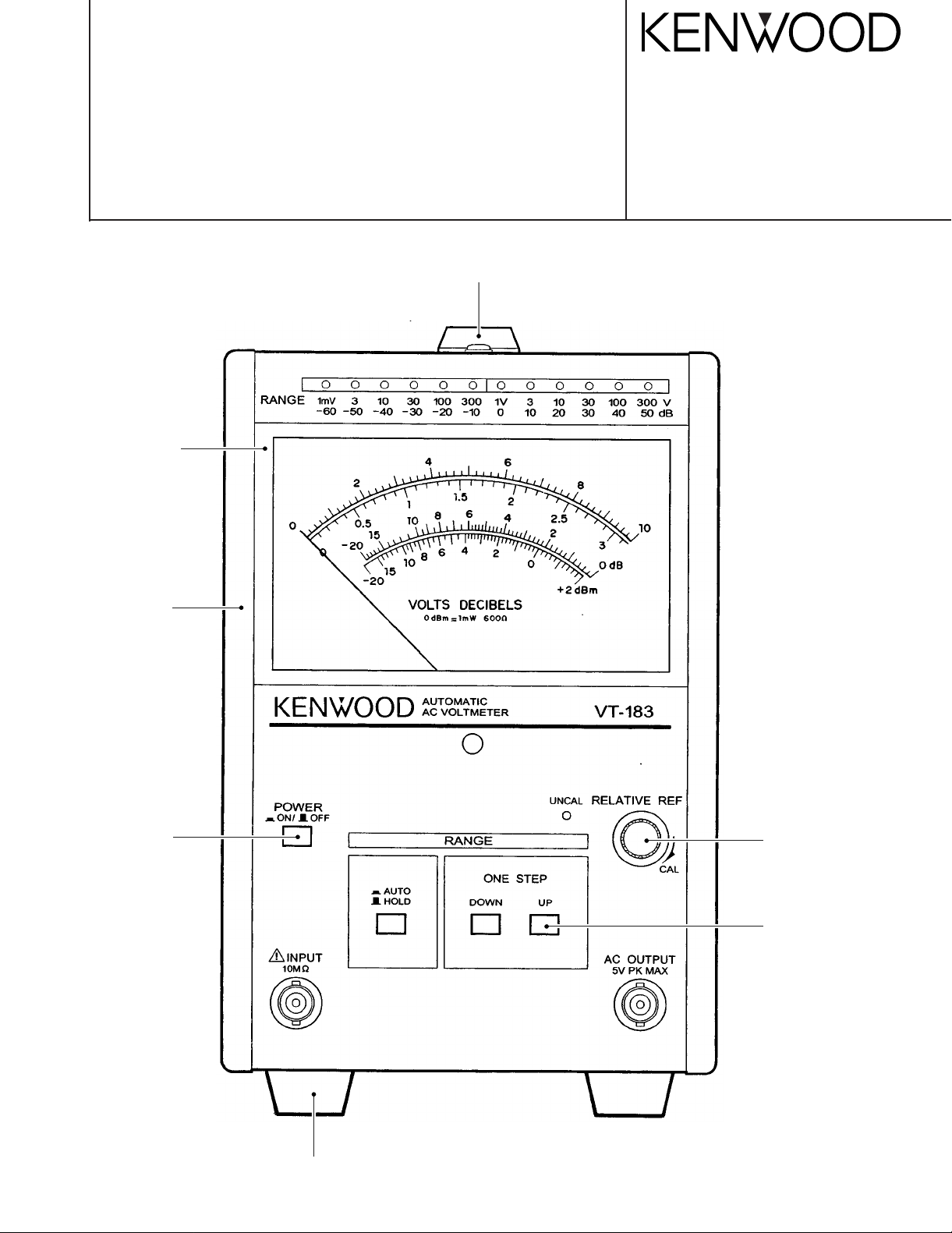
HANDLE : (K01-0564-08)
HANDLE COVER : (B09-0410-08)
FRONT PANEL
(A63-0302-08)
KENWOOD TMI CORPORATION
© 1998-5/B51-1133-00 (K/K)
SIDE FRAME
(A13-2254-08)
PUSH KNOB
(K24-3015-08)
KNOB
(K21-0961-08)
PUSH KNOB
(S68-0660-08)
RUBBER FOOT
(J02-0543-08)

VT-183
The following instructions are for use by qualified personnel only. To avoid electric shock,
do not perform any servicing other than contained in the operating instructions unless you
are qualified to do so.
SPECIFICATIONS..........................................................................................................3
SAFETY..........................................................................................................................4
CIRCUIT DESCRIPTION................................................................................................5
BLOCK DIAGRAM..........................................................................................................7
ADJUSTMENT................................................................................................................8
PARTS LIST (UNIT)......................................................................................................10
PARTS LIST (ELECTRICAL)........................................................................................11
SCHEMATIC DIAGRAM...............................................................................................14
P.C. BOARD .................................................................................................................18
WARNING
CONTENTS
2

Meter Section
Measure voltages
dB
dBm
Error
Frequency response
Input impedance
Max. input voltage
Stability
Residual Voltage
Amplifier Section
Output Voltage
Output resistance
Frequency response
Distortion
Signal to noise ratio
DC output Amplifier Section
Output voltage
Offset voltage
Output resistance
Frequency response
Environmental
Coefficient
Temperature
Relative humidity
Power Supply Section
Line voltage
Power consumption
Dimensions
WxHxD (mm)
Net Weight
Accessories
Power cable
Input cable
Replacement fuse
Instruction manual
Adjust driver
SPECIFICATIONS
1mV to 300mV in 12 ranges :
1, 3, 10, 30, 100, 300mV, 1, 3, 10, 30, 100, 300V full scale
–80 to +52dBm (0dBm=1mW at 600Ω)
Within ±3% of full scale at 1kHz
±10% at 5Hz to 1MHz,
±3% at 20Hz to 200kHz and
±2% at 30Hz to 100kHz as
reference to 1kHz response.
10MΩ +5% with less than 50pF parallel capacitance.
500V (DC +AC peak) 1V to 300V range
100V (DC +AC peak) 1mV to 300mV range
Within 0.5% of full scale for 10% line voltage fluctuation.
Less than 20µV with input shorted on 1mV range
Within
(Rated by signal-noise ratio in 1mV and 1V ranges. )
1V ±20% +offset voltage at full scale
Within ±3% at 10Hz to 1MHz
Within specification : 10 to 40˚C
Full operation : 0 to 50˚C
100/120/220/230 Vac ±10% 50/60Hz
128 (128) x 190 (210) x 239 (268)
Value in ( ) include protrusions
VT-183
–80 to +50dB (0dB=1V)
1Vrms (full scale) ±20%
600Ω ±20% at 1kHz
±3dB at 10Hz to 500kHz
Less than 1% at full scale
Over 40dB at full scale
±100mV
Less than 10mVrms
±0.08%/˚C
Less than 80%
Max. 7.5W
3kg
1 pc.
CA-41 1pc.
1 pc.
1 copy
1 pc.
3
VT-183
SAFETY
SAFETY
Before connecting the instrument to a power source, carefully read the following information, then verify that the
proper power cord is used and the proper line fuse is
installed for power source. The specified voltage is shown
on the rear panel. If the power cord is not applied for
specified voltage, there is always a certain amount of danger of electric shock.
Line voltage
This instrument operates using ac-power input voltages
that 100/120/220/230 V at frequencies from 50 Hz to
60Hz.
Power cord
The ground wire of the 3-wire AC power plug places the
chassis and housing of the instrument at earth ground. Do
not attempt to defeat the ground wire connection or float
the instrument ; to do so may pose a great safety hazard.
The appropriate power cord is supplied as an option that
is specified when the instrument is ordered.
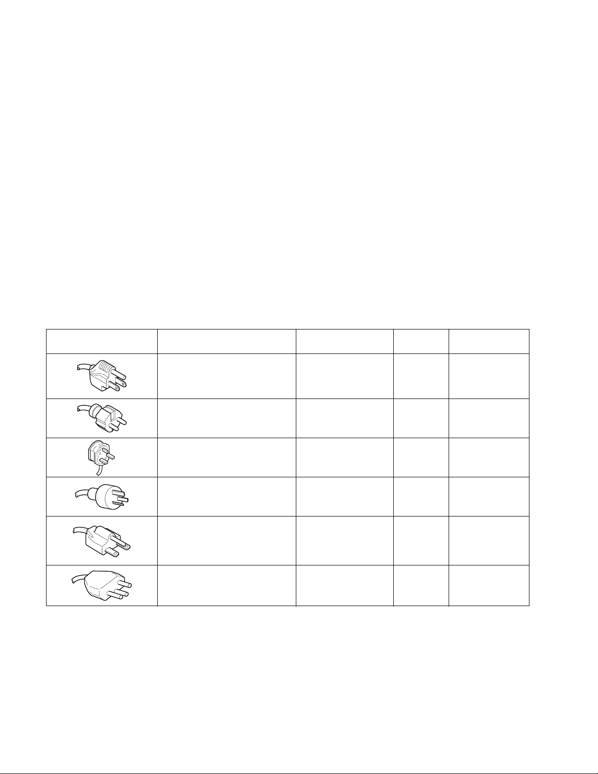
The optional power cords are shown as follows in Fig.1
Plug configuration power cord and plug type
North American
120 volt/60 Hz
Rated 15 amp
(12 amp max ; NEC)
Line fuse
The fuse holder is located on the rear panel and contains
the line fuse. Verify that the proper fuse is installed by
replacing the line fuse.
Voltage conversion
This instrument can be operated from 100 to 230V,
50/60Hz power source.
Use the following procedure to change from 100 to 230V
operation or vice versa.
1. Remove the fuse holder.
2. Replace fuse F1 with a fuse of appropriate value.
3. Reinsert it for appropriate voltage range.
4. When performing the reinsertion of fuse holder for the
voltage conversion, the appropriate power cord should
be used. (See fig.1)
Factory installed
instrument fuse
0.2A, 250V
slow blow
5x20mm
Line cord
plug fuse
None
Parts No. for
power cord
E30-1983-08
Universal Europe
230 volt/50 Hz
Rated 16 amp
U.K.
230 volt/50 Hz
Rated 5 amp
Australian
240 volt/50 Hz
Rated 10 amp
North American
240 volt/60 Hz
Rated 15 amp
(12 amp max ; NEC)
Switzerland
230 volt/50Hz
Rated 10 amp
Fig.1 Power Input Voltage Configuration
0.1A, 250V
slow blow
5x20 mm
0.1A, 250V
slow blow
5x20 mm
0.1A, 250V
slow blow
5x20 mm
0.2A, 250V
slow blow
5x20mm
0.3A, 250V
slow blow
5x20 mm
None
5A
Type C
None
None –
None
E30-1982-08
E30-1985-08
E30-1986-08
–
4

CIRCUIT DESCRIPTION
In studying the operation of each circuit in voltmeter please refer to "BLOCK DIAGRAM".
VT-183
General
This AC voltmeter is combined with Meter unit and Control
unit. Meter unit switch to different range according to the
remote control signal and display the result to the meter.
Control unit will output the remote control signal according to
the output of the Meter unit.
Description of Functional Circuits
Meter Unit
1) First Attenuator
It is the attenuator based on the resistance dividing method,
and its two-staged attenuation volume-one is 0dB(the range
between 10µV and 300mV),and the other is –60dB is converted by a relay.
2) Impedance Conversion Circuit
It is the circuit to convert the signals from the first-stage
attenuator into a fully low impedance in order to send it to
the second-stage attenuator (1mV–300V) .
3) Second Attenuator
A resistance divider act as a attenuator. The amount of
attenuation is switch in two steps by relay contacts:0dB and
–30dB.
4) Third Attenuator
A resistance divider network acts as an attenuator. The
amount of attenuation is switched in four steps by a FET
switch:0dB, –10dB, –20dB and –30dB.
7) Absolute-Mean Valve Detector
An absolute-mean value detector comprised of a high
through-rate and high gain amplifier. Which has a very good
linearity by negative feedback from the current flowing
through the Meter load. In switching, this provides a sufficiently wide frequency band so that the high frequency
phase compensation circuit is reset.
8) Attenuator Control
A logic control circuit comprised of a diode matrix and output
buffer transistors. This encodes a 12-bit signal from the
Decoder on the control board to a 6-bit signals, which control the First, Second and Third Attenuators. The remote
control connector is connected to this circuit.
9) Power Supply
The power source circuit supply ±5V DC from the AC input,
which contain a silicon diode bridge for full-wave rectification, high-capacitance electrolytic capacitors for smoothing,
and an IC regulator stabilization.
Control Unit
1) Pre-Amplifier
A wideband, non-inverting differential amplifier act as a preamplifier. Which has 50-fold gain and the purpose is to
buffer the signal from meter unit and then driving the two
rectifier circuit.
5) Main Amplifier
A wideband, non-inverting differential amplifier acts as a
main amplifier, which has high input impedance, Iow output
impedance and 20-fold gain. This output signal level is
20mVrms for the full scale read on the Meter .
6) Output Amplifier
A widehand, non-inverting differential amplifier acts as an
output amplifier, which has 50-fold gain and 600Ω output
impedance. The output signal level is 1Vrms for full-scale
read on the Meter, and works stable even for cpacitive
loads.
2) Rectifier
Two transistors to from a full wave rectifier.
3) DC Output Circuit
A non-inverting operational amplifier act as a DC output driver with 1V full scale voltage. The output impedance is
600Ω.
4) Peak Hold Regulation Circuit
Two transistors to from a full wave rectifier, and the peak
voltage is held by a smoothing capacitor.
5) Discharge Circuit
The peak voltage mention above will be discharge by a transistor frequently with a constant period.
5

VT-183
CIRCUIT DESCRIPTION
6) Differentiator
The oscillator output will pass through a RC differentiator
and then active the discharge circuit.
7) Up Comparator
The Up comparator will output a Up pulse when the output
of the peak hold regulation circuit is higher than the high reference voltage.
8) Down Comparator
The Down comparator will output a Down pulse when the
output of the peak hold regulation circuit is higher than the
low reference voltage.
9) Oscillator
The oscillator will generate a pulse for each 60msec, and
the pulse is use for the discharge circuit and the both
Up/Down comparator.
10) Up/Down Counter
The pulse from the UP/Down pulse control gate circuit will
trigger the Up/Down counter, and which output design the
attenuation range of the meter board.
11) Decoder
This decoder convert the 4-bit binary code from the
Up/Down counter to a 12-bit control signal which drive the
attenuator control on the meter board.
12) Up/Down Pulse Control Gate Circuit
The Up/Down pulse output from this circuit is depended on
the Mode switch. Under Hold mode, the output pulse are
generate from the Up/Down switch. On the other hand,
when under Auto mode, the output pulse are generate from
the Up/Down comparator and the Up/Down can over right
the Up/Down comparator.
6
 Loading...