


KEY TO SERVICING IS:
HOW TO READ THE SERVICE MANUAL
T
Once you understand this you can easily understand the TS
First step is
On page 107 find the BLOCK D
It should have been at the very front of the manual.
Then go to page 12 Receiver and page 17 transmitter and read through how the receiver / transmitter functions while following
his section is first because it is key to working on the Ts-940. It is not explained in the service manual.
-940.
download the manual from www.mods.dk.com, or other sites.
IGRAM. This is probably the most useful diagram in the book because it illustrates conceptually how the radio works.
From this you can easily follow through where major signals and functions travel.
through the block diagram. This will give very good idea of how the radio works.
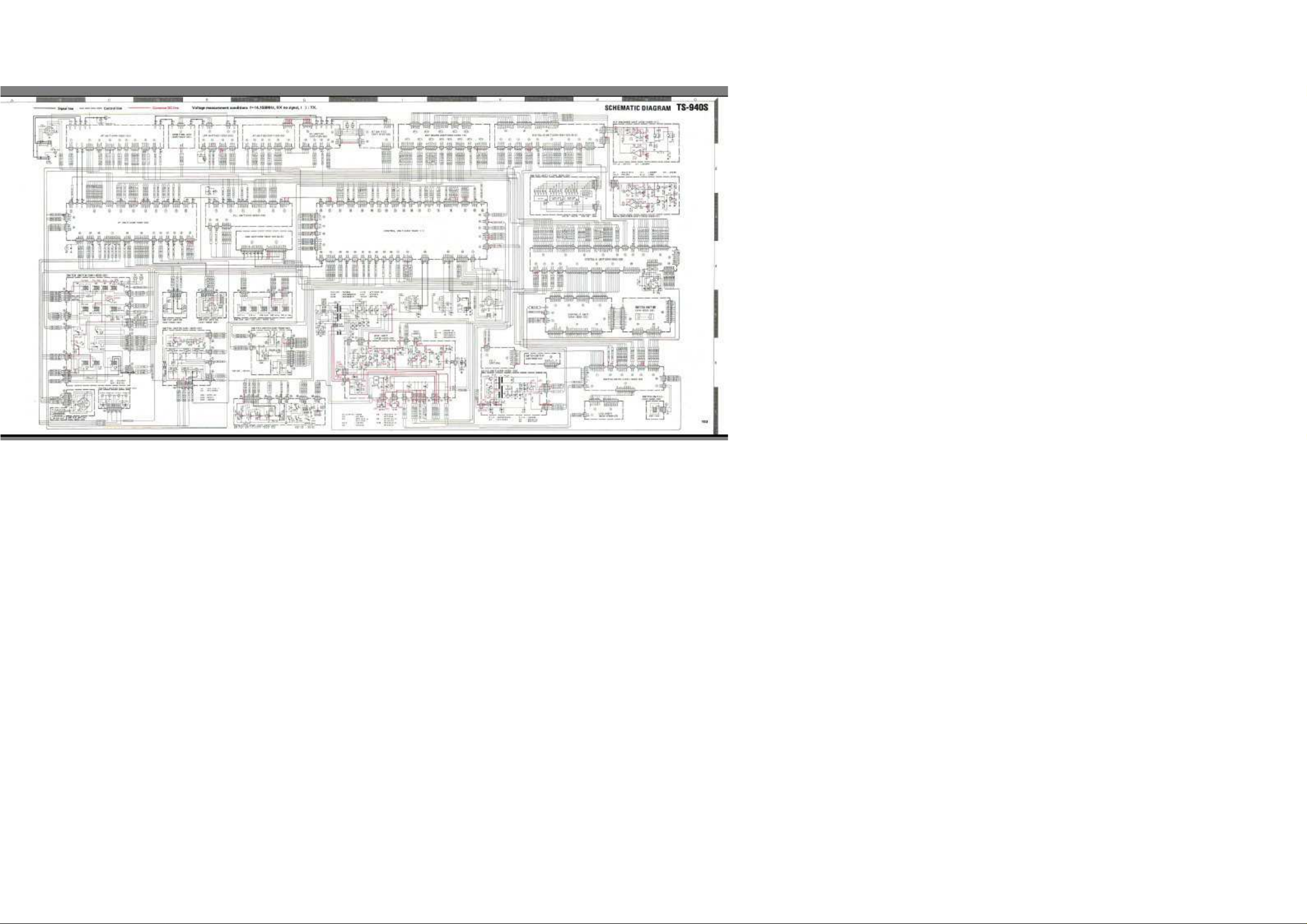
Then on page 103 find the overall schematic of the 940.
Now zoom into part of that schematic and look at example connectors:
This lays outs out all the major boards. There is a coding system, to trace between boards.

Best illustrated by worked example.
O
It has five wires:
Two example traces are shown below;
Wire 1
Wire 2
Wire 3
Wire 4
Wire 5
As you can see if you trace along
Using this system you can trace from any part of the 940 to any other part.
On each schematic or board layout diagram all you have to do is find the
n The PLL board X50-2020-00 find Connector Plug 2.
-DA0 shown with a destination tag “CAR-1-DA0”, whose destination is Carrier Board (X54-1840-00)(A/2) Connector Plug 1 –DA0 Wire 8,
-DA1
-DA2
-DA3
-UL1 shown with a destination tag “CAR-1-UL1”, whose destination is Carrier Board (X54-1840-00)(A/2) Connector Plug 1 –UL1 Wire 4,
all grouped wires through on the diagram, the grouped wire line leads from one board to another.
Connector Plug Number. Then you can easily trace through the board.

Page 83 to 89 of the service manual shows every
Page 80 and
WARNING: Please NOTE: There is no colour coding for wires listed in the service manual. IT IS VERY SAFE PRACTICE BEFORE TAKIN
CON
MULTIPLE WAYS TO PLUG IN WIRES, AND YOU COULD SERIOUSLY DAMAGE YOUR 940 IF YOU DONOTT DARW OUT WIRING
Using the above decoding method solved the following problems.
From: W5EJ
Sent: Friday, 18 August 2006 7:45 p.m.
To: jaking@es.co.nz
Subject: RE: Need help on 940 Wires
Jeff, after seeing your documentation on the 94
I picked up a used 940 and
Question.
terminal on the PCB to re
I don’t have another unit to reference and cannot find any pictures.
facing the unit this is the connector towards the rear of the unit and only connector on that board with just three wires) Cr
Any thoughts or help or pictures would be greatly
thanks
Connector Plug on every board is listed out with description of its function. This helps identify what the wire function is doing.
81 shows the physical location of most boards inside the radio.
G A BOARD OUT TO DRAW A DIAGRAM OF THE BOARD SHOWING EVERY
NECTOR PLUG AND THE COLOUR OF EEVRY WIRE. ONLY DOING THIS WILL GUARANTEE YOU PLUG THE WIRS BACK IN CORRECTLY. FOR THE IF BOARD AND CONTROL BOARD THERE ARE
COLOUR CODE PLUG IN DIAGRAMS.
0 I thought I'd send you a note and see if you could help me out.
appears whoever had it before me had replaced several connectors inside the unit with direct solder connections. (yes a mess).
On the Speaker/internal switch unit (left front top with cover top off) there are 3 connectors that plug into the right side of the unit. One has three wires, red orange and black. All three of mine are disconnected and I cannot tell which connector
-solder them too. (your wires would be in a connector)
do you have any pictures or 940's with the tops off could you let me know in what order front to rear the three wires are in your connector? (Of the three connectors on the right side
azy question I know. …….
appreciated.
73 - John (W5EJ)

From:
jaking [mailto:jaking@es.co.nz]
Sent: Monday, 21 August 2006 8:59 a.m.
To: 'jwill@verizon.net'
Subject: RE: Need help on 940 Wires
John,
I don’t have a TS
Then on page 103 overall schematic, find those connections.
You may have to look at board layout middle of p 102 to identify the co
Then find the same places on the schematic p 103.
Follow the wires through on the schematic to see which board and connector they end o
Find that other connector inside the radio, and get the colour of the wire from where it connects to the other board.
Then use a multi meter to verify you have the same wire at both ends. You would be best to un
Then you can reconnect.
There is no color coding in the manual so this is the only way to decode the wire colours.
For example ON PAGE 103 YO
Or 28 CV1 connects to IF board 14
So find IF board 14
This decoding systems works right through all 940 connections.
Let me know how you get on.
73s
-940 apart right now. But it is easy enough to figure out. Down load a service manual from www.mods.dk
nnector number and wire letter. Looks like connectors 48 29 and 30. You will see the letters for each number there.
n another board.
-plug the other end connector, before measuring continuity, because that way you are 100% you are only measuring on that wire only.
U WILL FIND 48 LG appears to connect to Switch L-49-LG
-CV1
-CV1, on the IF board and you will get the colour of that wire there. Un plug IF board 14-CV1, and use the meter to verify you have the same wire.

Jeff ZL4AI
From: W5EJ
Sent: Sunday, 20 August 2006 6:41 p.m.
To: jaking@es.co.nz
Subject: Re: RE: Need help on 940 Wires
Took your advise and
RECEIVER PERFORMANCE IMPROVEMENTS.
R1. KENWOOD PRODUCED 3 SERVICES BULLETINS which do considerably improve the receiver.
downloaded the manual, had the unit fixed in 30 minutes. Thanks for the help - John

AGC circuit improvement
http://www.kenwood.net/indexKenwood.cfm?do=DownloadFile&Document=2d13f766bec08d9297b
http://www.kenwood.net/indexKenwood.cfm?do=DownloadFile&Document=d02a8b1ae4c8a39115ff83f169f65a1895e42da53ae01ebf6db6adb98b2e
TS
http://www.kenwood.net/indexKenwood.cfm?do=DownloadFile&Document=09b9d746891ed0281dcc8482861e53da08bf66
TS
http://www.kenwood.net/indexKenwood.cfm?do=DownloadFile&Document=57aa76a9447b3b37e1e9f60965f865a395e42da53ae01ebf6db6adb98b2e
http://www.kenwood.net/indexKenwood.cfm?do=DownloadFile&Document=2e0ca5ad0e0e9060f7f850fe27f80b1a95e42da53ae01ebf6db6adb98b2e
http://www.kenwood.net/indexKenwood.cfm?do=Downl
KENWOOD TS
In early March I [Rich Maher] talked to someone at International Radio regarding the reciproca
1986 issue) and found that it had already been installed on my TS
newsletter), but in actuality measured 465 ohms.
At the time you indicated that was the first report you had received of the resistor value problem and recommended that I con
that a new fix fo
information.
Since receiving the bulletin from Kenwood, I have installed it on my TS
anyone experiencing reciprocal mixing problems install the new fix. It should be noted that some of the newer TS
lower than my own and found that the fix had been factory installed. Apparently, more than one manufacturing site is used and
produced at one location without the fix, while another site any have cut in the fix but is using numbers from a lower block.
The quickest way to verify whether the fix has been installed is to check R120 and R129 on the PLL Unit (X50
fix is already installed.
instructions in the bulletin state that when making the modifications to the RF Unit (X44
two capacitors has been filled with wax, it is definitely not easier.
definitely easier.
then try the receiver, CW signals
(one on each si
only 4 screws and tilting this unit towar
I hope the above information is helpful to you in dealing
with
-940S Signal To Noise Ratio Improvement With Noise Blanker
-940S VCO/Carrier To Noise Ratio Improvements
oadFile&Document=55221dd570b7e465e5087cf67f5e71fa95e42da53ae01ebf6db6adb98b2ed832baa0aa033a297d15598713460b315fbb
46280e3758b9b95e42da53ae01ebf6db6adb98b2ed832baa0aa033a297d15598713460b315fbb
d832baa0aa033a297d15598713460b315fbb
aab282a3fe0ec52cce1a1412bab3177362513310ffd26e29ff6af16615
d832baa0aa033a297d15598713460b315fbb
d832baa0aa033a297d15598713460b315fbb
-940S RECIPROCAL MIXING NOISE
l mixing noise problem with the Kenwood TS-940S. I had been in the process of installing the fix described in your newsletter (late
-940S (S/N 7100269). The factory installation had one problem, the resistors used for R120/R129 were color coded for 900 ohm (close enough to the 1K in the
Apparently, Kenwood had gotten a bad batch of resistors from some supplier and had not discovered the problem.
tact Kenwood. I called them and was told that they had not heard of the problem before. They also stated
r the reciprocal mixing noise problem had been developed and was described in a Service Bulletin dated March 2, l987. I requested a copy of the bulletin and have attached a copy of it to this letter for your
(See Issue No. 76, Pg. 30 and 31 for Kenwood Service Bulletin No. 917 and schematics pertaining to this subject.)
-940S and found it to make a very significant improvement in weak signal handling in the presence of nearby strong signals. I would recommend highly that
-940S have the fix installed. I was preparing to install the fix on a friends's TS-940 which had a serial number 100
serial numbers are given to each in blocks. Consequently, it is possible for higher serial numbers to be
-2020-00). If these two resistors are 3.3 ohms in value [Editor correction Service Bulleting 917 says 3.3 Kilo-Ohms], the
Do not depend on the on the absence of C176, C180 or C181 as an indication, as earlier attempts (factory or field) to correct the mixing noise problem may have removed these same capacitors. The
- 1660-00), it is easiest to move C132/C133 to the foil side of the board. As the component side of the section of the RF Unit containing these
The factory installation of the fix left C132/C133 on the component side and installed the R154/C193 and R155/C194 series RC networks on the foil side. This is
As a side note, the installation of the fix took me about 2 hours. Both the PLL Unit and RF Unit modifications must be completed before the transceiver is usable. If you install just the PLL Unit modifications and
will should like raw AC. Also, to make life simple, do not remove each of the boards above the PLL Unit individually. The easy way to gain access to the PLL Unit is to remove the top two screws
de) holding the front panel and loosen the bottom tow screws. This allows the front panel to be tilted forward. The speaker assembly and all the boards above the PLL unit may then be removed as a unit by removing
ds the front of the TS-940S. No cables need be removed from the boards above the PLL Unit.
the reciprocal mixing noise problem. (Thanks, Rich

Maher, WZ4Z, 1117 NW 7th St., Boynton Bea
ch, FL 33435)
RECEIVER 2.
FIELD EFFECT TRANSISTORS AROUND THE WRONG WAY.

In September 2004 PY1NR announced he had discovered:
See PY1NR web site
and
http://www.eham.net/articles/9261
Initially
the drain where the source was sup
As FETs normally allow current flow until the gate has a potential, I wonder if this really makes that much difference.
PY1NR suggest that reversing these transistors will provide 10 dB of gain. But this claim does not
improvement by reversing the FETS.
Garey Barrell provides Kenwood’s advice
==================================================
From: kenwood
Sent: Wednesday, 9 March 20055:53 a.m.
To: Kenwood@mailman.qth.net
Subject: Re: [Kenwood] RE
Jeff
OK.....
+++++++++++++++++++++++++++++++++++++++++++++++++++++
Dear Kenwood Customer:
This information pertains to the TS
The circuit designer said the installation of
The PCB view in the Service Manual is correct too. The schematic is the only section that is in error. The schematic indicate
source of one FET connected to the source of the second FET.
In addition, testing at Kenwood Communications in
matched pair). Replacing only one FET at a time can affect sensitivity.
If you need further assistance, please e
Sincerely,
had been drawn on the circuit boards and mounted in the reverse orientation to that shown in the Kenwood Circuit Diagram.
www.guisard.com
ZL4AI found it hard to understand this website and actually what PY1NR had discovered. Starting with the circuit board layouts I tried to draw out the circuit: What I found was that apparently the FETS were mounted with
posed to be and vice-versa.
-bounces@mailman.qth.net [mailto:kenwood-bounces@mailman.qth.net] On Behalf Of Garey Barrell
-
Just in from Kenwood...
appear be based on before and after measurement. It would be useful to have some feedback on whether others have had much
======= =============================
:TS-940 What is the correct FET direction?
-940S component location.
Q10 in the actual TS-940S transceiver is correct.
Long Beach, CA showed poor results. Sensitivity can become unstable. The most important point about the Q10 pair is that both FET's must be replaced at the same time (like a
-mail us again.
s the drain of one FET connected to the source of the second FET. The correct installation is to have the

Kenwood Amateur Radio Customer Support
++++++++++++++
73, Garey
Atlanta
From: Garey Barrell [k4oah@mindspring.com]
Sent: Friday, 11 March 2005 7:26 a.m.
To: jaking@es.co.nz
Subject: Re: [Kenwood] RE
Jeff
OK.
The Q4 situation is not quite as clear.
drawing
such an error.
FETs are installed in the orientation shown.
The guys at Kenwood, both in LA and Japan, are pretty frustrated with the whole mess!
also mentioned that replacing one of the pair was not
but we surmised they selected for
The big question is, these transceivers have been working and meeting
73, Garey
Atlanta
===============================================================================
-----
From: Traian Belinas [mailto:traian@deck.ro]
Sent: Tuesday, 5 April 2005 9:34 p.m.
To: jaking@es.co.nz
Subject: Re: Ts
Hi Jeff,
++++++++++++++++++++++++++++++++++++++++++++
- K4OAH
:TS-940 What is the correct FET direction?
-
I just had a discussion via phone with the Amateur service department at Kenwood.
The schematic appears to be correct, (sources tied together or push-pull,) and the board layout
appears to be incorrect. According to a tech in Japan, the FET's in the actual unit are correct. They have not found any instance where they were reversed in the actual radio or any 'in-house' docs that could have resulted in
I guess someone is going to have to open one up and look at the traces! Looking at the board traces in the component layout, it certainly appears that one FET has the Source and Drain connections reversed if the
Perhaps the board traces were changed? [ZL4AI editor comment: Boards made exactly as shown in the Service Manual]
recommended. The original circuit used a matched pair and they recommended replacing them only with a matched pair. They were unable to describe the "matching" process,
Idss, and possibly transconductance.
specs for 15+ years, so who cares!? :-)
- K4OAH
They tried to duplicate the Q10 situation, and found that performance was degraded considerably when the PY1 "correction" was made. They
Original Message-----
-940 All problems SOLVED .. Possibly for you too!

The website is and will be great.
Will look carefully at.
I have two things to say.
First is that the second mixer Q4 JFET is indeed wrong mounted.
Here are attached
The PCB traces are symmetrical, the mixer should be balanced, and as the two
FETs are identical type, the way that they are mounted is obviously wrong.
As I said, I have reversed the Q4 and the improvement exist, but it is not
so
pictures, you can use them on the website.
great as other had reported (the sensitivity goes improved by 2 to 3 dB)


===============================================================================
After reading Kenwood’s Garey’s and Traian’s advice, I turned around only Q4 o
The result was a quieter receiver. I do not believe that there was any significant gain increase in the receiver.
I would appreciate (and will post on this page) emails describing others experience regarding this change.
From Kenwo
I also became interested in the RX mod you mention. Before opening my 940, I decided to first check whether drain and source
because I own a "dead" 940 RF board as a sou
I collected one of the 2SK125s from this board and built a source
-
n the IF board.
od.net on 25/4/05
Hi Dale
of the 2SK125 are symmetrical or not. This was easy for me
rce of parts for future repair of my rig.
-grounded test configuration with a 5K resistor connecting drain to +8V. Then, I fed a sawtooth test signal (about -6 to
1V) via 10K into the gate. U(drain) was recorded against U(gate) on a DSO (Tek 468). Thereafter, I repeated the measurement with drain and source exchanged.

I obtained the
characteristical FET response curves and these were exactly (!) identical in both configurations. This did not change when the test frequency was increased to 10 MHz. It
seems, therefore, that the 2SK125 is symmetrical.
As a consequence,
Like others, I also believe that there is not much to improve. My 940 h
the entire RX). The IP3 is +18 dBm (I once replaced the band switching diodes by PIN diodes).
Like others, I often had connector problems afte
Best 73
Thomas (DF5KF)
THEN TRAIAN PROVIDES MORE OVERVIEW
-----
From: Traian Belinas [mailto:traian@deck.ro]
Sent: Friday, 29 April 2005 2:05 a.m.
To
Subject: Re: FW: ts
Regarding the TS940 2SK125 preamp, yes the FETs have this interesting
feature
amplifiers where the
be as low as possible for obtaining lower out to in feedback when used for common source applications... So, even if symmetri
by inverting the D/S for the TS940 Q10 may be still not high (I don't intend to do it because of the reason explained before)
obvious that it is not ok, even if it works... An counterexample is also the TS950 (both SD and SDX) which use the same Rx pr
actually build as sho
Please let me know if any other new info about the 940/950.
Tnx
73,
Traian
PY1NR provide
PY1NRFeedback
,
Original Message-----
i decided not to correct the layout error in my 940.
as an RX sensitivity of about 0.15 µV (10 dB S/N) on all bands (well, I must say it was worse until I re-aligned
r working in the 940 - another reason only to go into this rig when necessary.
: jaking@es.co.nz
: for low signal/low freq and/or low DC, they are symmetric. This is why they are used as passive variable low resistance/attenuator/switching for low signal with rather good results. The things are changing at HF/VHF
-940
interelectrode capacitances became important (do you remember about neutralising a FET preamp?), and these are not quite symmetrical, as the devices are manufactured so that the drain to gate capacitance to
cal, why to use it as for having the greatest unwanted out ot in capacitance/feedback? The gain obtained
, but the engineering feel tell us that something is not ok there... And regarding the second mixer, there it is
eamp as the TS940 with 2SK125 and 2SK520 (they are all FET cascade preamps) but for the 950 it is
wn in the diagram, no drain/source inverting there (maybe the same for their second mixer), so which of them is the best regarding this, the 940 or the 950?!
,
s feedback and re-endorses previous statements on turning the FETs around

From: ts
-940@yahoogroups.com [mailto:ts-940@yahoogroups.com] On Behalf Of John Rotondi
Sent: Friday, 17 March 2006 10:51 p.m.
To: ts
Subject: [ts
Dear Fellow TS
Just a quick post to let others know this information, which you can use as you see fit:
I have now fixed
significant increase in received signal levels, wit
effectively document this in a scientific manner, I could not effectively
When I mentioned this to one of my RACES group leaders
documented results: after each FET was reversed, we found a 1 S
Now, there is much conjecture regarding the
of signal, which means the fix has increased receive gain 10 to 12 db. Cert
-
At any rate, this was my experience, which I humbly offer to the TS
Wishing you all good DX!
73,
John, WA2OOB
Vent
On Mar 19, 2006, at 1:53 AM, Jeff King wrote:
-940@yahoogroups.com
-940] FET Reversal Fix Notes
-940 users-
2 TS-940SATs according to the findings of PY1NR who first detailed the reversal of 2 FETs in the TS-940, based on factory mistakes in the PCB silk-screening. After doing my own radio, I absolutely found a
h no audible increase in noise floor. I wondered why other users were not rushing to do the fix- and then saw several posts denying the validity of the fix. However, since I did not
offer valid 'proof' of the results.
- who also owns a TS-940- he decided that we would to do the 'fix' to his unit- but this time, we would document the results using a repeatable local test signal. The
-unit improvement in received signal level using our local test signal in the 20 meter band, for a total of 2 S-units receive gain improvement.
dB value of S-units, and other TS-940 users may know what these 2 S-units on the TS-940 meter mean in terms of dB. Generally, from my research, each S-unit may represent 5 or 6 dB
ainly nothing to sneeze at: being able to give one of the finest receivers made the full scope of RF gain that it was originally intended to have
at no cost, and without negative repercussions? As the bands wane on the downside of the sunspot cycle, and running only a vertical 10 feet off the ground, I am finding I can use all the noise-free gain available to hear DX!
-940 user community.
ura, CA

John,
found
your report very very interesting.
Despite all the controversy, some of which I have reported on
http://homepag
I would appreciate if you could you please confirm you turned one FET around, ran signal test, identified improvement 1 S uni
identified improvement 1 S unit?
Y
hope
73s
Yours sincerely
Jeff King zl4ai
es.ihug.co.nz/~jaking/TS-940_02.htm
t and then Turned other FET around and ran signal test,
ou know it would be helpful if Kenwood would actually confirm their view of whether the FET in correct position results in too much gain.
to work you one day! and

*From:* John
*Sent:* Sunday, 19 March 2006 11:56 p.m.
*To:* jaking@es.co.nz
*Subject:* Re: [ts
Hello Jeff!
Very nice to hear from you! Thank you for your interest in my
I have seen your excellent
all
Just a bit on my background: I am a professional sound eng
recording
ears
1) Set up the signal source: my MFJ
2) Set up the TS
Note that the MFJ
3) Tuned the TS
Note that I moved the radio around a bit to ensure that the
4) Shut
5) Reversed the first of the FETs, reinstalled it's PC board
6) Powered up the test so
There was a full 1 S
7) Shut off the test source.
8) Reversed the second of the FETs, reinstalled
9) Powered up the test source, and tuned the TS
Rotondi, WA2OOB [mailto:wa2oob@earthlink.net]
-940] FET Reversal Fix Notes
posting on this topic.
website- thank you for providing such valuable information to the user community. I am still reading through
the information regarding PIN diodes, and may mod my radio in that area as well.
ineer, and have been designing/building/maintaining/operating professional music
and TV/Film post production facilities for many years. When I first did the FET fix to my TS-940, the results were obvious to my
. In doing the second radio with my friend, we systematically followed these steps to document the results relative to an external repeatable test signal, independent of band conditions, QSB, etc.:
-259 antenna analyzer with whip antenna, to generate a signal near 14.200 MHz.
-940 with a small whip antenna on the work table, about 4 feet from the test source.
-259 RF test signal is fixed in level, so this would not be a variable in these tests.
-940 to this test signal, peaking the carrier reception in USB mode, and recording the maximum S-meter reading.
reading was stable and repeatable, and not sensitive to relative position.
off the test source so as not to deplete the battery while working on the radio.
, installed the whip antenna, and positioned the radio as for the original measurement.
urce, and tuned the TS-940 to it as before.
-unit increase in received signal level.
it's PC board, installed the whip antenna, and positioned the radio as for the original measurement.
-940 to it as before.

There was now another full 1 S
-unit increase in received signal level over the previous measurement, giving 2 full S-units total over the original base reading.
directly
would
In liste
otherwise
this
audio
such
folds
The 940 receive audio quali
to
I can only think that some amateurs did not have the same
with
I hope this information is helpful to you! And yes
a
I will look forward to a QSO with you on HF!
73,
John ,
Editors Note:
While this is probably not as sophisticated as if we would have used a Communications Monitor (IFR, Marconi, etc.) or other test system
coupled to the receiver, with stepped calibrated attenuators, and RF voltmeters coupled to the IF of the TS-940, we felt that it
be a fast way to have valid empirical data to verify that we had created an improvement, rather than a disability, for the TS-940. BTW, post fix listening on air clearly showed the significant gain improvement.
ning today on 10 meters on my own TS-940, I know that this additional gain has brought signals to the readable level that would
have not been readable. I have also done extensive listening tests with extremely strong local broadcast signals to determine if
fix has compromised rejection of extraordinarily strong out-of-band signals, or has resulted in compromised receive RF or
intermod or other non-linearities resulting from component saturation, imbalance, or interstage distortion- but have heard no
issues. I will mention that my recently purchased IC-706 MK II (for mobile use), of more recent design and with some DSP, totally
up from same broadcast interference that has no effect on the 940!
ty remains exemplary. I have been pleased with the results of the fix, and feel it was worth the effort
realize the full potential of the original design intent.
results because perhaps the FETs were not closely enough matched to begin
, or they had other problems, such as bad solder joints as often found in these units?
- it would be nice if Kenwood would enlighten us on these issues- but as the radio is not
current product, and did quite well even with this 'defect', they have little motivation to do so.
WA2OOB

John has undertaken some very useful me
asurements and it is very useful to have some measurements.
Measurement outcomes could be more factual if a change in signal to noise ratio was measured by laboratory methods described
http://p1k.arrl.org/~ehare/aria/ARIA_MANUAL_TESTING.pdf
http://www.arrl.org/~ehare/testproc/testproc.pdf
If someone could do an
Garey Barrell sensibly advises:
Even a good test, i.e.,
would be limited by external noise regardless!
I suspect Garey is correct about the noise floor: This is a less than 0.2 microvolt receiver: Maybe turning the FETS around p
to noise ratio?
If first before an FET swap the S meter was calibrated against a signal generator, then signal strength against independent s
then a reading of the independent signal
I wish Kenwood would behave like a responsible manufacture
Have a look at the following links which show how measuring receiver improvement is a difficult undertaking. Even definition
http://www.sherweng.com/table.html
http://www.rac.ca/opsinfo/smeters.htm
http://www.seed
http://www.w8ji.com/receivers.htm
by the ARRL. For example MDS.
MDS noise floor test before and after the FET swap, it would be more complete evidence of the assumed improvement.
s+n / n measurements before and after, or _accurate_ noise figure measurements really wouldn't impress me that much, since a receiver meeting the Kenwood specs
roduces more noise, [which of course lifts the S meter] but does it produce any more signal or better signal
ignal source measured, then an MDS measured, then after the FET swap the s meter was again re-calibrated,
sourceand separately MDS again would show that it was just not an increase in noise.
r and explain the technical reasons they do not recommend turning the FETs around.
of what you are measuring requires some considerable reading and comprehension.
-solutions.com/gregordy/Amateur%20Radio/Experimentation/SMeterBlues.htm

RECEIVER 3.
STOP: T
“The I.F
Communications_1_2_with_Kenwood_Japan
Kenwood Japan have now changed their mind and confirmed
“The I.F
Swapping R149 and R150 probably incre
Please review
KI4NR advises the rising S meter caused is leaking in C128 and C130.
When time permits C130 [and / or other AG
separate communications about IF circuit diagra
SUMMARY OF R149 AND R150 MIS
THERE IS NO AGC TIMING CORRECTION
his modification was suggested following Kenwood Japan’s advice, that
circuit diagram was correct and the I.F. board was labelled incorrectly.”
circuit diagram is incorrect.
Communication 3 with Kenwood Japan
KI4NR’s email below advising the (Kenwood intended) correct construction was electrical layout of the AGC identical to the TS-930.
ases sensitivity to similar degree as achieved by just turning the AGC off
KI4NR_email
On the Editors radio C128 has been replaced and does not fix the rising S meter.
C capacitors] will be replaced and when replacement has been shown to remove the rising S meter this web page will be updated to confirm that. At that time this section of the web page will be restructured to
m from the rising S meter problem.
-LABELLING

Kenwood appears to have done the following:
Please note there are 2 mistakes.
1. First incorrectly labelled the schematic: (with resistor values around the wrong way)
2.
(For example the positio
Then incorrectly labelled the PC board [to correct the mistakes on the schematic] so correct resister values put in circuit.
n of R150 was labelled as R149 on the PC Board, which resulted in a 150K resistor being put at the R150 position.)

Areas in grey below should be
Significantly improves the AGC timing function: After modification:
disregarded.
- You hear weak signals a lot better.
- S meter with AGC SLOW ON becomes quite responsive and lively in the region of S1 to S4 signals.
--Before S meter did not move much in S1 to S4 region.
--Before it would take a strong signal to lift the meter suddenly to S4.
I always wondered why the TS-940 behaved differently to other transceivers [TS-930S, TS950SDX] which react much faster over S1 to S4.

Mike KC8ZNW o
Hello everyone I have a question about the movement of my 940's meter. It seems that it
barely moves on some signals which are perfectly readable, other
have even heard
increase when I switch the antenna to it for the same signal.
Is this an effect of the sensitivity of the receive section? Or do I have a malfunction? In
addition my VFO exhibits the o
the knob. I understand this may be caused by solder joints.
TIA, Mike KC8ZNW
Executive Summary of AGC Mod
Its
When fixed,
Simply swapping 2 resistors around, will enable this rig to hear as Kenwood designed and intended in Kenwood’s original circu
The error is on the IF board:
Kenwood printed labels for R149 and R
As assembled by the factory, (the outcome is) in the main signal path, a 2,200 Kilo
Being 14 times larger the 2,200 Kilo
Swap the resistors around and the receiver hearing improves significantly!!!
Kenwood have confirmed the resistors are in the wrong place. Their emails are below:
Probably “these resistors in the wrong place” occurs in every TS
Independent Feedback on how Receiver Improves
n 25/4/05 describes this same behaviour to the Kenwood.net.
an occasional 10DB+ movement. My TS830S will give me a 2 or 3 s-unit
ccasional hiccup on the last 2 digits on small movements of
easy to modify a TS-940S to hear better (or as well as) a TS-950SDX.
TS-940 really pulls out those very weak signals.
sigs give me 8 or 9 and I
it diagram.
150 around the wrong way!!!
-Ohm resistor ends up where a 150 Kilo-Ohm Resistor should be.
-Ohm resistor (incorrectly) significantly degrades the signal.
-940S produced.

1.
From: Ed [mailto:ca.urso2@verizon.net]
Sent: Monday, 23 May 2005 7:18 a.m.
To: jaking@es.co.nz
Subject: TS
Also, your
wo
had
resistors
73,
Ed
USA
Full email at:
2.
From:
Sent:
To:
Subject:
Hi Jeff,
I was looking through the 940 page and found m
some luck with
-----
From:
Sent:
-940S
AGC Timing Correction was applied on my rig (SN 806XXXX) and
rked great! Sure enough, resistors R149 (68K on my equip) and R150 2.2Meg
been incorrectly installed by the Mfr. The board markings for those
were wrong.
Alves KD6EU
FeedbacK_3
el34guy@aol.com [mailto:el34guy@aol.com]
Thursday, 23 June 2005 4:46 p.m.
jaking@es.co.nz
agc modification
y feedback to you(regarding the AGC modification with resistors 149 and 150) under the alc setting portion. Im sure I mislabeled my original email to you on this(think I wrote alc). I am having
changing out the 2.2 meg for a 1 meg resistor. Im thinking maybe a little lower value might be worthwhile to test also, like a 6-800k ohm value.
I know I received another email from you on this but I just wanted to let you know it looked like my feedback was in the wrong spot on your page.
Original Message-----
el34guy@aol.com [mailto:el34guy@aol.com]
Sunday, 12 June 2005 9:43 p.m.

To:
jaking@es.co.nz
Subject:
Jeff
is worth considering in there. There
73
Mark
[
changed around on the Editors 940 AGC
3.
-----
From: Michael Feryok II [
Sent: Saturday, 9 July 2005 9:57 a.m.
To: jaking@es.co.nz
Subject: A
Hey Jeff,
Thanks so much for your TS940 page it helped a co
stations that are buried into the noise floor now. Mike, K
From:
Sent:
To:
Subject:
My friend and I
noise level. Adjusted the VR3 for a proper zero on the meter and
worked
Very low noise compared to before the swap. I highly recommend it.
Thanks to everyone here, and Jeff ZL4AI,
I'm
Re: alc mod
I thought that mod might be a little better than it was for the alc. It made my radio appear as if it was in fast agc mode all the time. There wasnt a lot of smoothness in the ssb signal that Im used to. Like I said, maybe something like a 1.1 meg
isnt much room to solder at all in there. Geez, its tight.
Editors Note: ZL4AI questions the validity of these observations but has included them to keep feedback information unbiased. Varying the resistors from Kenwoods values was never recommended or intended. With resistors
slow is still very much slower than AGC fast.]
Original Message-----
GC Mod
mailto:mikeferyok@yahoo.com]
-worker and I today to swap the R149-150 resistors for the AGC mod. Very apparent improvement in noise level and gain. I can hear
C8ZNW
ts-940@yahoogroups.com [mailto:ts-940@yahoogroups.com] On Behalf Of mikeferyok
Saturday, 9 July 2005 9:53 a.m.
ts-940@yahoogroups.com
[ts-940] AGC mod works great!!
did the R149-R150 swap and it improved the gain and
LZ1YE and YV5YMA right after on 17 meters!
still debating the transistor gain swap.....????
Mike KC8ZNW

4.
From:
Sent:
To:
Subject:
Hello Mi
come is like yours. I'll post after I get my 940 back and let everyone
know how it goes. I have a very late model serial number which is
20700050 and it still had both mistakes in it, so I h
improve on the already great
improved TS
---
> My friend and I
> noise level. Adjusted the VR3 for a proper zero on the meter and
> worked
> Very low noise compared to before the swap. I highly recommend it.
> Thanks to everyone here, and Jeff ZL4AI,
>
5.
-----
From: Articles@eham.net [
Sent: Sunday, 24 July 2005 3:52 p.m.
To: jaking@es.co.nz
Subject: [Articles] Im
Posted By KB9IV
Well I finally got around to the AGC mod.
decreases di
Forget the "FET reverse" project.
Best 73,
Bill
-----
From: Bill & Becky [
Sent:
ts-940@yahoogroups.com [mailto:ts-940@yahoogroups.com] On Behalf Of Dale
Tuesday, 12 July 2005 5:37 a.m.
ts-940@yahoogroups.com
[ts-940] Re: AGC mod works great!!
ke, I'm having both mods done to my 940 now and I hope the out
-940S. Dale, KD5UVV
In ts-940@yahoogroups.com, "mikeferyok" <mikeferyok@y...> wrote:
did the R149-R150 swap and it improved the gain and
LZ1YE and YV5YMA right after on 17 meters!
I'm still debating the transistor gain swap.....????
ope this will
recieve on the 940. 73 and enjoy your
Mike KC8ZNW
Original Message-----
stortion.
mailto:Articles@eham.net]
prove TS-940 Receiver for Weak Signals
What a fantastic difference.........it also improves CW to my ears. In addition the AGC mod also seems to improve useable weak sensitivity and
NO difference here, it's not worth the risk and time.
KB9IV
Original Message-----
mailto:wmarvin@hickorytech.net]
Sunday, 24 July 2005 4:00 p.m.

To: jaking@es.co.nz
Subject: 940 AGC Change
Hello Jeff,
Thank you for the info on the "AGC" correction.
Makes a good 940 a great 940........I can now hear much better not.
Have a Great Day!!
73
Bill
6.
http://www.eham.net/articles/11090
7.
-----
From
Sent: Friday, 29 July 2005 4:03 a.m.
To: jaking@es.co.nz
Subject: Your 940 observations
Jeff
I appreciate your efforts on the 940. I have to say the AGC deal is not quite right. I have work on more 940 that I can
placement on the board is correct.
when AGC switch is in the fast
has been sitting is the Capacitors are leaky and by swapping the resistors around helps correct that problem. I have had 940'
KB9IV .......Minnesota
What a fantastic difference here!!
I found the FET reversal change useless...........not worth the bother.
Original Message-----
: John [mailto:hydroaction@cfl.rr.com]
remember. I have known for years the silk screening of the numbers on the circuit board is wrong. but the resistor
also the service manual is wrong on the schematic. The 2.2 Meg ohm resistor is in parallel with C-127 .....the 68K or 150K resistor is in series with C-126 which give you the base line time constant
postion. This is the CORRECT arrangement. Also if you look at the TS -930 that has the identical AGC circuit this is how it is on that radio too. The reason why you get the AGC rise when the radio
s have the rising S meter problem and changing and the caps C128, C130 in the AGC fixed it. This circuit is

a Hi impedance type with FET very sensitive and crazy things happen. I have check many, many 940 I have repaired new and old
schematic to see what I am taking about.
73 John KI4NR
Editors note:
On the TS
R730
and
R710 68K
-----
From: LPC Wireless, KI4NR [mailto:lpc
Sent: Friday, 29 July 2005 5:39 a.m.
To: jaking@es.co.nz
Subject: More Info ... Your 940 observations
Jeff
I forget to add something.
the switch does not function there. That why people say the meter is more jumpy.
schematic this is the correct circuit in every way and the way Kenwood intended it to work and how the 940 is
One other
radio are hotter sensitivity wise, better AGC compression. I use a 5 mil TS 940 wit
Also Kenwood put an
8.
serial numbers and have not found one yet that had the resistors in wrong. Look at the TS-930
-930 signal board the equivalent AGC resistors to R150 and R149 are:
2.2M
Original Message-----
wireless@cfl.rr.com]
When you swap the resistors around. you are putting the 2.2 Meg ohm in series with C-126. this effectively removes the Base line time constant to all AGC positions on the switch including AM even thou
plus the 150 K or 68 K bias the gate of Q23 more heavy and allows the receiver to stay more sensitive to low level signals. if you look at the TS-930
thing .....on all the older 940 4, 5 and early 6 mil serial number ...the IF board is different. The gain distribution in not the same. All the 940 ... late 6 and newer had better IF boards. They have more gain TX & RX the
h a later model 8 Mil IF board in it .......much , much better !!
S meter slam mod in those boards. all the older 940 when you shut the radio off, pin the S meter over. The newer boards are fix for that.

From: Jeff King
[mailto:jaking@es.co.nz]
Sent: Monday, 1 August 2005 8:01 a.m.
To: 'css@kenwood.co.jp'
Cc: 'lpcwireless@cfl.rr.com'
Subject: RE
Dear
Thank you so much for your 2 emails sent in March 2005 [attached as below].
COMMUNICATIONS_WITH_KENWOOD_JAPAN
From your advice I understood:
“The I.F
Because your advice was v
http://homepages.ihug.co.nz/~jaking/TS
This has been seen by some TS
A very experienced Kenwood repair expert from the USA very strongly suggests your advice may not be correct.
With the greatest of respect to Kenwood Corporation and yourself I ask please:
Could you please review your advice and advise again if R150 and R149 on the IF Board should be swapped around to make the TS
============================================================================
30 July 2005:
Abbreviated summary of key points in Emails from KI4NR Kenwood Repair Expert in USA
When R149 and R150 are swapped around the AGC does not function as
-
-
-
Mr T.Soranaka
circuit diagram is correct about positions of R150 and R 149 and the I.F. board is labelled incorrectly.”
RE: Is your advice Correct about TS-940 R149 and R 150: being in wrong places???
About R149 & R150
aluable I recorded this to a small web page:
-940_02.htm
-940 enthusiasts. It enables one to adjust a TS-940 to operate as (you advised) Kenwood designers really intended.
The reasons he states sound correct and are very convincing: Those reasons are summarised below.
-940 to operate as Kenwood designers really intended?
Kenwood intended.
The service manual is wrong on the schematic.
The silk screening of numbers on the circuit board are reversed to the schematic and wrong in relation to the schematic (only).
But the resulting resistor placement on the board is correct.

I believe the silk screening on the 940 IF board is correct and the IF schematic is wrong.
The 2.2 Meg ohm resistor is in parallel with C
The 2.2
Fixed AGC on AM.
Also if you look at the TS
(R730 2.2M and R710 68K, are the equivalent resistors on the TS
When you swap R149 and R150 around.
This effectively removes the Base line time constant to a
and allows the receiver to stay more sensitive to low level signa
73 John KI4NR
LPC Wireless
lpcwireless@cfl.rr.com
Phone: 386
=========================================================================
Mr T.Soranaka I look forward to receiving your advice.
Yours sincerely
Jeff King
-127 .....the 68K or 150K resistor is in series with C-126 which gives the base line time constant when AGC switch is in the fast position. This is the CORRECT arrangement.
meg ohm resistors in both the TS-930 and TS-940 sets up the bias to the FET from the 3.2 volt AGC reference voltage. The 68k or 150k in series with the Cap set up the base time constant. The other FET switch in for slow AGC on SSB and
-930 (both schematic and signal board) that has the almost identical AGC circuit.
-930.) The TS-930 is the correct circuit in every way and the way Kenwood intended "the AGC of the TS-940" to work.
you are putting the 2.2 Meg ohm in series with C-126.
ll AGC positions on the switch including AM even thou the switch does not function there. That is why people say the meter is more jumpy. Plus the 150K or 68K bias the gate of Q23 more heavy
ls.
-774-9921

9.
----
-Original Message-----
From: Customer Service Section [mailto:css@kenwood.co.jp]
Sent: Tuesday, 2 August 2005 6:01 p.m.
To: jaking@es.co.nz
Subject: Re: RE
Dear
Please accept my apologies for having supplied incorrect information.
A very experienced Kenwood repair expert from the USA is right.
The service manual is wrong on the schematic.
Yours sincerely,
T.Soranaka
++++++++++++++++++++++++++++
Customer Supp
Kenwood Corporation
(Japan)
URL:
Email:
++++++++++++++++++++++++++++
10.
From: John Brush [mailto:brushj@comcast.net]
RE: Is your advice Correct about TS-940 R149 and R 150: being in wrong places???
Mr.King,
ort Center
http://www.kenwood.com/
css@kenwood.co.jp

Sent: Monday, 12 September 2005 2:29 p.m.
To: jaking@es.co.nz
Subject:
Jeff,
I absolutely agree with the comments made by John KI4NR. A rising S
response was the same for both the
resolved by replacing
I must have one of those old IF boards, because my S
73, John (WA3CAS)
THE PRODUCTION MISTAKE DESCRIBED:
TS-940S R149/R150 More Info
-meter reading is due to a leaking capacitor, and not the incorrect placement of R149/R150. In my case, I did the resistor swap and noticed that the S-meter’s
AGC’s Fast and Slow positions – not good. After undoing the resistor swap, I now had the rising S-meter problem (a problem I didn’t have before the modification). In my case, the problem was
C126, the capacitor that is in series with R150 (2.2M) as shown on the schematic. Per John’s advice, I also plan on replacing C128 and C130.
-meter pegs when I turn the radio off.

Below is Page 92 of the Revised Service Manual
Observe that:
Below is
You wi
-R 149 and R 150 are mounted between almost the same connections. I.e. between the junction of C127- R148 - C128 - C130 - R156 to-> C126 - Q21 - Q22
-The difference being that “additional C 126” is between R150 and C126 - Q21 - Q22
page 93 of the Revised Service Manual
ll notice that R 149 is connected between C126 and the junction of C126 - Q21 - Q22. That is R149 has been mounted where R 150 should be.

Does
quickly. [
This is in the heart of the AGC timing section.
Probably all TS
================================================================
TO CHANGE THE RESISTORS
putting the 2.2M ohm resistor where the 150 ohm Resistor should be make a difference.
similar to the AGC in a TS-930]. AGC could not respond quickly before because it had to wait until C126 charged up.
-940s have R149 and R150 in the wrong place.
Yes! You bet
.
Change the 150 ohm back to the direct circuit and the AGC responds very

Change around
is easy.
You will need to take the IF Board out.
The difficult part is removing and putting all the connectors off / on the board.
Before starting, draw a diagram of the board showing each connector and position and colour of its wires.
That makes it c
If you don’t draw a diagram you will not know where all the connectors go back. Some two pin connectors could easily go in mo
These colours are not
I suggest you put in new resistors, because with longer leads they will slightly easy to hold in place while soldering.
THE INITIAL PROBLEM SYMPTOMS:
ertain you put the right connectors back in the right places.
shown in the service manual.
re than one place. That’s could be disastrous

ZL4AI discovered this while searching for the a fault described
below
AGC:
Only happens in SSB:
If TS
with
goes
tur
back
SSB in normal position, and TS
Needle is initially at s0.
During the first 25 minutes if you switch between off
then
If TS
but
Meter needle goes full scale right in all positions (off
normal
It takes longer say 4
ts
=========================================================================
After R149 and R150 changed back to positions Kenwood intended in the circuit dia
-
-
-940 left not running for a couple of days, when you turn it on,
the AGC turned off or set in fast position, then the meter needle
to up 25db + 9 (approx). The signal is diminished like RF gain
ned up. Over the next 25 minutes the meter needle slowly moves it way
to S0.
the needle goes back to zero in less time ... say 20 minutes.
-940 left for a couple of months, and then turned on same behaviour
worse.
-940 turned on this does not happen.
- fast - normal
- fast -
)
0 minutes for the needle to move to the s0. then
-940 functions as described above.
gram, the result was:
The fault of the rising S meter when cold disappeared.
S meter dropped back to S1 on both AGC OFF and AGC SLOW, with no antenna signal. Needed to adjust VR3 to bring the S Meter to S0.

ACKNOWLEDGEMENTS TO PERSONS
WHO HELPED SOLVE THIS
T.Soranaka Kenwood
install
Traian Belinas
traian@deck.ro
who
obvious the circuit was not assem
Garey Barrell
'k4oah@mindspring.com'
Who provide some very useful advice on functions of components and explanations how to read the circuit
=========================================================
A CAUTION
Not all IF boards are identical.
I installed another IF board installed as per factory spec with R149 and R 150 in their other components position in my TS
==============================================================
COMMUNICATIONS WITH KENWOOD
Japan was most helpful. You will see in the emails below Kenwood have readily confirmed that these components are around the wrong way. Then in a third communication (above) confirmed they are correctly
ed.
diagnosed the problem and really understands these circuits. Traian appears to have amazing skill and after reading the symptoms pointed me to look at R149. From there it became
bled according to the circuit diagram.
=====
diagrams.
:
-940. It did not have the rising S meter problem. But it was not sensitive to weak signals
JAPAN BELOW:

-----
Original Message-----
From: Customer Service Section [
Sent: Tuesday, 15 March 20057:11 p.m.
To: jaking@es.co.nz
Subject: Re: Question about TS
Dear Customer,
Thank you for your reply. I suppose that currently R149 and R150 are mounted correctly
comparing the circuit diagram. The circuit diagram is correct.
Yours sincerely,
T.Soranaka
++++++++++++++++++++++++++++
CustomerSupportCenter
Kenwood Corpora
(J
URL:
Email:
++++++++++++++++++++++++++++
-----
From: Jeff King
To: 'Customer Service Section'
Cc:
Sent: Tuesday, March 15, 20051:53 PM
Subject: RE: Question about TS
Dear T.Soranaka
Thank you for your advice.
Could you please advise if it would be advisable to sw
Yours sincerely
Jeff King
-----
From: Customer Service Section [
Sent: Monday, 14 March 200510:29 p.m.
To: jaking@es.co.nz
Cc: kcc
mailto:css@kenwood.co.jp]
-940 R149 and R 150: Appear to be in wrong places!
as the screen printing lettering R149 and R150 are reversed. Please confirm actual resistors
tion
apan)
http://www.kenwood.com/
css@kenwood.co.jp
Original Message -----
k4oah@mindspring.com ; traian@deck.ro ; Bill Bailey ; Ken McVie
-940 R149 and R 150: Appear to be in wrong places!
ap R149 with R 150 and vice versa, so the TS-940 functions in accordance with the circuit diagram?
Original Message-----
mailto:css@kenwood.co.jp]
-amateur@kenwoodusa.com; sabura.tech@kenwood.com.au

Subject: Re: Question about TS
-940 R149 and R 150: Appear to be in wrong places!
Dear Customer,
We are sorry for
R149 are 2.2M and 68K or 150K respectively as shown in the Service Manual.
Yours sincerely,
T.Soranaka
+
CustomerSupportCenter
Kenwood Corporation
(Japan)
URL:
Email:
++++++++++++++++++++++++++++
-----
From: Jeff King
To:
Cc:
Sent: Saturday, March 12, 20056:41
Subject: Question about TS
Dear Kenwood Customers Services,
I have found that when emailing Kenwood
this to. So I am sendin
Thank you for your recent replies.
While trying to find a fault in my TS
w
This means:
Specified in First Service Manual:
R149 68K
R150 2.2M
Spe
R149 150K
R150K 2.2M
Resistors as actually installed on my board if you follow the logic of the circuit diagram.
R149 2.2M
inconvnience. I have checked with our communication department as to R149 and R150. Unfortunately reference number of R149 and R150 on the borad are reversed. R150 and
+++++++++++++++++++++++++++
http://www.kenwood.com/
css@kenwood.co.jp
Original Message -----
css@kenwood.co.jp ; kcc-amateur@kenwoodusa.com ; sabura.tech@kenwood.com.au
k4oah@mindspring.com ; traian@deck.ro ; Bill Bailey ; Ken McVie
AM
-940 R149 and R 150: Appear to be in wrong places!
USA about a Kenwood USA product I got redirected to contact a Kenwood representative close to my home location. I am not sure who is best to send
g it onto to all Kenwood contacts.
-940 I have been going over the IF board. It appears to me when the board was made it was marked with the screen printing lettering of R149 being
here R150 should be and vice versa. I have followed the board traces both in the Service Manual and on the back of a board, and these resistors both seem to be in the wrong place.
cified in Revised Service Manual:

R150 150K
I have two IF boards here and they both have the resistors installed as required b
for every TS
-940 ever made.
I cannot understand how the circuits would function as the designer intended, as the installed resistors are very different t
advise if my observation is correct, and after later when Kenwood has investigated if it would be advisable to swap
At this time could you please just confirm that
I look forward to your reply.
Yours sincerely
Jeff King ZL4AI
RECEIVER 4.
This improvement is not fully documented yet. Please send in information.
4.1: Background
y the screen printing and hence on both boards both resistors are reversed. Possibly this is the case
o those shown on the schematic diagrams. Could you please
R149 with R 150 and vice versa?
the question will be investigated?
PIN DIODE IMPROVEMENTS
on how Pin Diodes were discovered to improve radios.

[
Chester Alderman
Wed, 17 Sep 1997 17:14:45
TenTec
invented, designed, manufac
until within the last 20 years or so.
Dont
and the other sid
(but each side is doped diffe
junction, thus the name PIN. The speed
throught
What all of this means is that PIN diodes are relatively
however
ECONOMICS.
Corsair
mentioned
I read Rhode's article on PIN diodes and decided I could improve the IM performance of my Omni 6 (it didn't need it!!), so I
Packard PIN diodes that Rhode stated were the best, and installed them in
in
TenTec
through
So the bottom line is if you replace the PIN or silicon diodes in a rig, you will see (hear) practically no improvement, UNLE
utilize
probably
At 01:32 PM 9/17/97
>
>>
>>
>>
>>
>>
>>
>>
>>
>>
>
>
>
>
>
>
>
>
>
>
>
>
>
>
TenTec] Pin Diodes / Paragon
chestert@pressroom.com
-0400
builds a great amateur radio and obviously to give you a 'million dollar radio' that cost the user five bucks, economics really does have to enter the picture. PIN diodes have been around for many years, however they were initially
tured, and sold to be microwave switching devices, obviously because you can not use mechanical relays for internal switching within a microwave RF circuit. It has not been developed as a 'low frequency' device
quote me on this because I've been out of microwave design for too long. A regular diode is a piece of silicon (or germanium) that has a junction. One side of the junction is doped, during mfg process, to have an excess of electrons (+P)
e of the diode is doped to have an excess of holes (-N), therefore the term PN junction. And of course a PN junction diode will pass current (a signal) in only one direction. A PIN diode has these (almost) same characteristics
rently than than a standard diode), and in addition, between the +P and the -N sections is a third section that is doped specifically to allow the diode to switch VERY rapidly, and this region is called the Intrensic
that a PIN diode can switch is basically determined by the width of this Intrensic area, the narrower the I junction, the faster it will switch and therefore the higher the rf frequency that you can pass
it. Unfortunately, to build a PIN diode that will switch at HF freqs (below 30 MHz), the I junction has to be made wider, or the diode will switch too fast to allow one cycle of an HF signal to pass through it.
expensive. A regular PN junction diode (typically a 1N4148 for instance) may cost 5 cent apiece,
a 'cheap' true PIN diode will cost between one and three dollars apiece; and thats why you do not see them in very many amateur radios.
(I'm not sure why it took that much verbage to explain, but it did.)
II's used a regular silicon switching diode, 1N4148 to switch the filters. The Omni 6 does use PIN diodes, but probably because of the above
economics, TenTec uses diodes that 'will do the job' verses expensive PIN diodes.
bought the expensive Hewlett-
my Omni 6. Over the past five years using my Omni, chasing DX and participating
some serious DX contest, I have yet failed to see where these expensive HP PIN diodes made any substantial improvement.
runs about 10ma of current through their production PIN diodes, in order to gain the full IM advantage of the HP PIN diodes, you must run 80ma
the HP PIN diodes!
SS you redesign the circuitry to
the diodes operating at their optimum design specifications. Probably if you find the filter switching diodes in your rig are running 'hot' to your touch, it
means that someone has taken the time to change the current running through the switching diodes to really improve the IMD.
-0400, you wrote:
H. M. 'Puck' Motley W4PM wrote:
I have the feeling that the pin diodes in question are a modification
suggested in an article by Ulrich Rhode (not sure of the spelling of his
name) a few years back concerning 2nd order IMD in modern rigs. One of
the rigs mentioned was the Paragon. The article stated that by replacing
the common switching diodes used to switch the receiver front end band
pass filters with a certain type of pin diode, 2nd order IMD could be
improved. Maybe some of our more technically oriented folks remember this
article and can comment in greater detail. This is all I remember so if
you have additional questions don't ask me!
Thanks, Puck. I was certain it was something Rohde said, just wasn't
quite sure when or what the exact reason was. I just spoke to Ten Tec
about this, and they actually said they had tested different types of
diodes to switch the Paragon's receiver filters, and settled on regular
switching diodes because there wasn't much difference with other types.
So, I guess replacing the receiver filter switching diodes with PIN or
other (hot carrier, etc.) types is probably a mod that some users have
done themselves. At least I know for sure it's not a factory
modification.
Is there anyone out there who knows this for sure? Has anyone done the
aforementioned mod? I know one fellow recently mentioned in a message
that a rig he had for sale had the mod. Now I'll go search for the Rohde
article. 8^)
73, KE3KR

4.2 RadCom Technical Topics explains what Pin Diodes were supposed to achieve.

TECHNICAL TOPICS April 1995
RF SWITCHING
TT FEBRUAR
receiver design". He subsequently published a series of th
look" (QST, December 1994). In these articles he stressed that for receivers intended to have a
an important limitation. He has recommended the use (or substitution) of such special
Dr Rohde's articles encouraged Tom Thomson, WOIVJ, to investigate how bad in practice are the more distortion
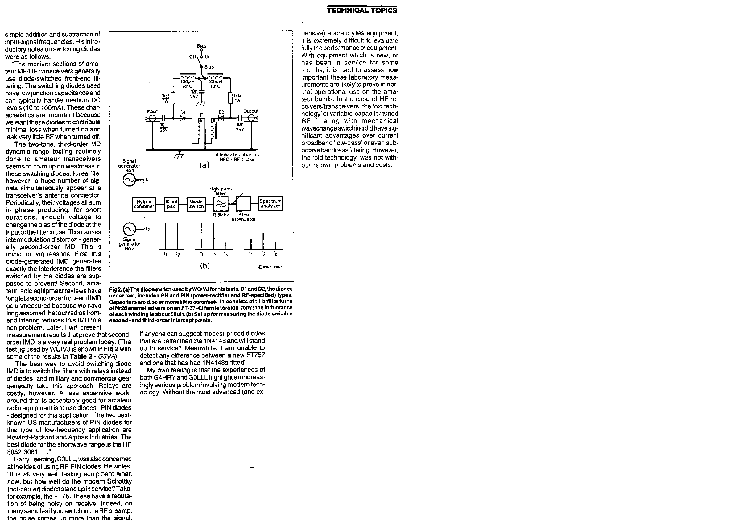
RF switching and tuning diodes', QST, December 1994). He carried out laboratory tests on four types of diodes: The IN4153 gen
Siemens PIN switching diode; and th
He has tabulated results in terms of diode switch insertion loss (dB) at 1O MHz with 0, 5, 10 and 20mA bias currents; and sim
conclusions: "RF
the 1 N4007 makes it seem attractive as a low
RF
He adds: 'The manually switched and tuned front
today. More attention paid to front
Dr Rohde in commenting on W0IVJ's
20
not
I TUNING DIODES
Y 1993 REPORTED briefly an important article by Dr Ulrich Noble, KA2WEU/DJ2LR, which was published simultaneously in English and German QST and CQ-DL November 1992) on "Recent advances in shortwave
ree articles (QST May, June and July 1994)on Key components of modem receiver design, and a recent follow-up Key components of modern receiver design: a second
very wide dynamic range, the intermodulation distortion that arises from the use of unsuitable RF switching and tuning diodes imposes
-purpose RF diodes as the Hewlett-Packard HP5082-3081 PIN diodes.
-prone switching diodes and how good are those designed for low distortion ('Exploring intermodulation distortion in
eric PN switching diode: the Motorola MPN 3700 PIN diode intended for RF switching; the BAT-17
e low-cost 1N4007 which is a generic 1 kV-PIV rectifier diode with a PIN structure but not intended for RF switching
ilarly the second- and third-order intercept points (IP2, 1P3 and dBm). He draws the following
-specified PIN diodes are the devices of choice for low-distortion switching at HF and above, for band pass filter selection and C switching in a narrow-band pre-selector. Although the presence of a PIN structure in
-cost alternative to RF-specified PIN diodes, its insertion-loss performance When unbiased and reverse-biased - and its IMD performance when unbiased - is demonstratively interior to
-specified PIN diodes.
-end filters of the 1960s and 1970s had much to offer in terms of second-order IMD, but we need not retrogress to those techniques to achieve improved 1P2 and 1P3 performance
-end filtering in general can produce the improvement we need."
finding, notes that many amateurs had reported difficulty in obtaining HP5062-3081 diodes. He recognises that even with the Motorola MPN3700 with a US price Of less than £11 replacing all
-plus filter-switching diodes can be expensive. Nevertheless he recommends changing all the diodes between the antenna and the first mixer, which includes the diodes on both sides of the band pass filters of a transceiver but
the transmit/ receive switching diodes which typically are already high-quality PIN types. He also adds some notes on Japanese switching diodes which might be used to replace the 'bad' diodes seen in the past".


TECHNICAL TOPICS December1995
SWITCHING DIODES: DJ2LR/KA2WEUs REPLY
THE ITEM 'RF Switching Diodes Controversy 'TT, July 1995, included G4HRY's criticism of the advice given by Dr Ulrich
several popular amateur HF transceivers could be improved by judicious substitution of PIN diodes, such as the Hewlett Packar
based solely on RF losses and that G4HRY had not made any IMD measurements. I added that I was sure that Dr Rohde could provi
be right to include G4HRY's v
The detailed measurements provided by G3SBI (TT, November) and those published by DB1 NV in
insertion loss and in IMD performance and that IMD is significantly affected both by the forward current through the diode an
As a result of an unfortunate delay, the N
experiments. As a matter of record, I would like to point out tha
changes in a TS50. The itemi
'This validates my statement that this was a repeatable effort and the changes
the Collins KWM380, one of which I still own and whose noise figure is on target with 0.3uV without a pre
correctness of my OST article.
1
whether or not the European version had different diodes or relays. Before fingers are pointed at specific diodes, I would li
1 may want to supply one set of more modem diodes.
"Everyone who has contacted me as the result of the OST articles had been advised not to use the HP 3081 (for reason
through ICOM dealers/repair centres. Those diodes are much less expensive and more readily available.
"To the best of my knowledge, the companies who c
transmit
"Finally, there is no qu
transceiver which uses PIN
Roinde, DJ2LR/KA2WIEU/4, in his excellent articles in OST that the second order IMD performance of
d HP5082-3081 , specifically intended as RF switching diodes. I pointed out that the criticisms were
de a convincing reply. However, in view of his experiences with GKPT's Omnii VI 1 felt it would
iew that it was unwise to put unquestioning faith in published articles including even those in OST and RadCom.
VHF Communications showed clearly that there is a wide difference between different diodes used for RF switching both in
d by frequency.
ovember item was written before I received a fax sent by Dr Rohde on July 18th. This, in a slightly abridged form, reads: I feel really concerned and sorry about G4KPT and the results of his
t intentionally
1 had not changed any of the diodes myself. but had the authorised service departments of AES, Milwaukee replace the diodes in the Yaesu FT890; ICOM changed the diodes in two IC765s; and Kenwood made the same
sed ICOM repair bill shows 0.12uV for 12dB SINAD, I also had the other companies involved validate that following the diode changes, the receivers were within specifications.
were not done at the expense of performance in any respect. It is also a matter of record that the HP5082-3081 diodes were used in the production of
-amplifier and whose 2nd order IMD is superior to other diode applications. This should remove any doubts as to the
have had no experience in modifying an Omni VI nor did I do any measurements or modifications with it. The ARRL edited in the Omni VI because it is a popular US-made transceiver and there had been some discussion as to
ke to examine the circuit diagram because there can be no need to change all 40 diodes. As an experiment,
s of cost and availability) but rather to use a Siemens BAR17 diode or M1204 diode, which is available
hanged the diodes in the equipments involved did not change the diode bias. It is questionable why any one should wish to change diodes in the IF section; similarly diodes in the
/ receive switches should not be touched.
estion that relays provide the best of all worlds as far as IMD characteristics are concerned, but not necessarily the best solution in terms of space and costs. 1 have just tested a soon-to-be-re leased
-type di odes and exhibits superb IMD characteristic while maintaining a good noise figure.

"As to multi
-tone functionality, once 2n and 3rd order IMD tests have been done, on can predict the higher-order IMD effects, especially since they are based on diode characteristics and this type of test is a legitimate test to
evaluate receivers.
"Hopefully, your readers will not deduct from this experiment that QST or other reputable magazines publish articles which ar
In a subsequent letter, dated September
set
In regard to Dr Rohde's endorsement of the technical accuracy of articles, I would enter a caveat.
particularly in column produced to a tight deadline. Many years ago I stressed that I regard Technical Topics as forum for ne
given on experiment
often provide useful additions to amateur lo
=========================================================================================================
Intermodulation properties of switching diodes, by Dr. Ing.
19, 1995, Dr Rohde confirms that he has run into a lot of people who have modified their RF switching diodes and have been extremely happy with the results. Further, after refining his test
-up he finds the improvement is now slightly more dramatic than outlined in his QST article.
al ideas still under development! I welcome comments from sceptical readers or those spotting printing errors etc. Fortunately, there is good evidence that the vast majority of 7T items do work as intended, and
re!
e technically incorrect."
While most writers strive lo complete accuracy. the mechanics an Murphy's Law of publication make it difficult to avoid some errors,
w ideas, not all of which are likely to prove repeatable or even strictly accurate No guarantees can be
Jochen Jirmann, DB1NV

ZL4AI was contacted by a neighbouring ham, (known for many
years). Peter Johnson ZL4LV. peter.Johnson@Paradise.Net.Nz
Peter designed and developed from scratch in the early 1970s an HF transceiver. (Actually it is still under development and m
Association under Peter’s guidance sold this as a kitset. Peters design was the first use of diodes for band switching. Peter
transceivers appeared with diodes switching bands. As the inventor of the concept Peter has collected articles on diode switc
ay soon have BA479s installed.) The local Branch of the New Zealand Amateur Radio Transmitters
published this technique in English Radio magazines the early 1970s and thereafter the first commercial
hes, and provided the following.


FOR THE SUBSEQUENT SECTIONS CLICK HERE: www.jking.kol.co.nz/ts-940_02_part2.htm
 Loading...