

Page 1

HF TRANSCEIVER
TS-850S
INSTRUCTION MANUAL
KENWOOD CORPORATION
©PRINTED IN JAPAN B62-0061-10(K, X)(T)
92/12 1110 987654321 91/12 1110 9 8 7 6 5
Page 2

Thank you for purchasing this new transceiver.
IMPORTANT
Please read this Instruction Manual carefully before
placing the transceiver in service.
SAVE THIS INSTRUCTION MANUAL
The following explicit definitions apply in this manual:
Note ; If disregarded, inconvenience only, no
risk of equipment damage or personal
injury.
Caution : Equipment damage may occur, but not
personal injury.
This Instruction Manual covers the TS-850S, with
and without AT (Automatic Antenna Tuner) unit.
When there are differences in operation, separate
instructions will be given for each model.
Illustrations show the TS-850S with AT unit.
Notice to the user:
One or more of the following statements may be
applicable to this equipment.
FCC WARNING
This equipment generates or uses radio frequency
energy. Changes or modifications to this
equipment may cause harmful interference unless
the modifications are expressly approved in the
instruction manual. The user could lose the
authority to operate this equipment if an
unauthorized change or modification is made.
Information to the digital device user required by
the FCC:
This equipment has been tested and found to
comply with the limits for a Class B digital device,
pursuant to Part 15 of the FCC Rules. These limits
are designed to provide reasonable protection
against harmful interference in a residential
installation. This equipment generates, uses and
can generate radio frequency energy and, if not
installed and used in accordance with the
instructions, may cause harmful interference to
radio communications. However, there is no
guarantee that the interference will not occur in a
particular installation. If this equipment does cause
harmful interference to radio or television
reception, which can be determined by turning the
equipment off and on, the user is encouraged to
try to correct the interference by one or more of
the following measures:
Reorient or relocate the receiving antenna.
Increase the separation between the
equipment and receiver.
Connect the equipment into an outlet on a
circuit different from that to which the
receiver is connected.
Consult the dealer for technical assistance.
_____
CONTENTS
1. BEFORE OPERATION
2. SPECIFICATIONS AND ACCESSORIES
2-1. SPECIFICATIONS
2- 2. ACCESSORIES ..........................................6
3. INSTALLATION AND CONNECTION..................7
3- 1. INSTALLATION
3- 2. CONNECTION
4. OPERATION .....................................................10
4- 1. OPERATING CONTROLS .......................10
4-2. INITIAL SETTING ........................................19
4-3. SSB OPERATION
4-4. CW OPERATION
4-5. FM OPERATION ..........................................25
4-6. AM OPERATION ..........................................26
4-7. FSK OPERATION
4-8. PACKET (AFSK) OPERATION
4-9. AUTO ANTENNA TUNER OPERATION
4-10. OTHER OPERATION ................................31
4-11. MEMORY
4-12. SCAN
4-13. DRS FUNCTION
4-14. REPEATER OPERATION ..........................45
4-15. OPERATION WITH A PERSONAL
COMPUTER
4-16. VOICE SYNTHESIZER
4-17. DIGITAL MODULATION FUNCTION
4-18. Transfer function when two TS-850S
transceivers are connected together
4-19. When used as the master machine for the
transverter .................................................49
4- 20. Remote control function..........................51
5. CIRCUIT DESCRIPTION
5- 1. BLOCK DIAGRAM
5- 2. CIRCUIT DIAGRAM
6. MAINTENANCE AND ADJUSTMENTS.............62
6- 1. GENERAL INFORMATION
6-2. SERVICE ......................................................62
6-3. CLEANING ...................................................62
6-4. IN CASE OF DIFFICULTY
6-5. ORDERING SPARE PARTS.........................64
6- 6. ADJUSTMENTS
7. OPTIONAL ACCESSORIES
7- 1. FILTER INSTALLATION ...........................67
7-2. VS-2 VOICE SYNTHESIZER
INSTALLATION
7-3. DRU-2 DIGITAL RECORDING UNIT
INSTALLATION
7-4. SO-2 TCXO UNIT INSTALLATION
7-5. DSP-100 DIGITAL SIGNAL PROCESSOR
CONNECTION ............................................69
7-6. TL-922/922A LINEAR AMPLIFIER
CONNECTION ............................................69
7-7. SM-230 STATION MONITOR
INSTALLATION
7-8. AT-850 AUTOMATIC ANTENNA TUNER
UNIT INSTALLATION .................................70
7-9. AT-300 AUTOMATIC ANTENNA TUNER
CONNECTION ............................................70
7-10. OTHER ACCESSORIES ...........................71
8. REFERENCE
...................................................
...........................................................
....................................................
.......................................
...........
.........................................
..........................................
...........................................
........................................
.........................................
........................................
.....................
........
........................................
.............................................
..............................
.........
...........
..................................
...................................
.................................
.......................
...........................
.......................................
.............................
..........................................
..........................................
...............
..........................................
20
22
27
28
37
43
46
46
46
52
52
53
62
63
64
67
67
68
68
69
73
3
4
4
7
7
30
41
47
Page 3
1.
BEFORE OPERATION
TO PREVENT ELECTRIC SHOCK, FIRE AND OTHER INJURY. PLEASE NOTE THE
FOLLOWING:
V - !
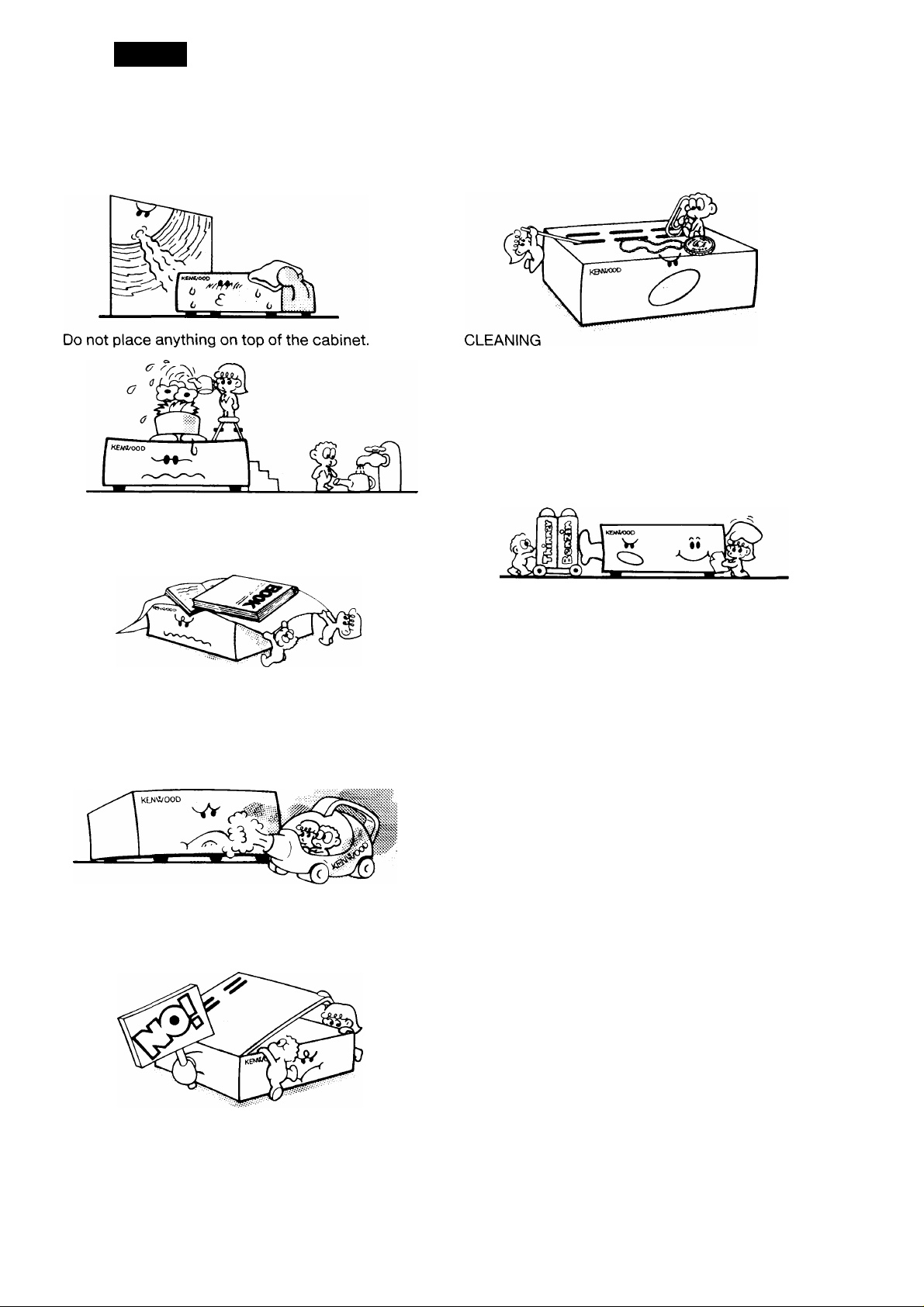
Do not place this unit, where it will be exposed to
direct sunlight or close to heating appliances.
To ensure good ventilation, do not put anything on
top of the cabinet and allow at least 15 cm (6
inches) of space behind the unit.
Do not drop pieces of metal, needles, coins and
other electrically conductive materials into the unit.
1. Turn the power off, before cleaning the unit.
2. Do not use any type of abrasive pad, thinner,
benzine or any substances which may damage
the unit.
3. Wipe the front panel and other exterior surfaces
of the unit with a soft dry cloth or a soft cloth
lightly moistened with water.
Do not place the unit in areas of excessive dust,
high humidity or on unstable surfaces.
v'-X
To avoid risk of electric shock, under no
circumstances should the unit be opened:
Page 4
2. SPECIFICATIONS AND ACCESSORIES
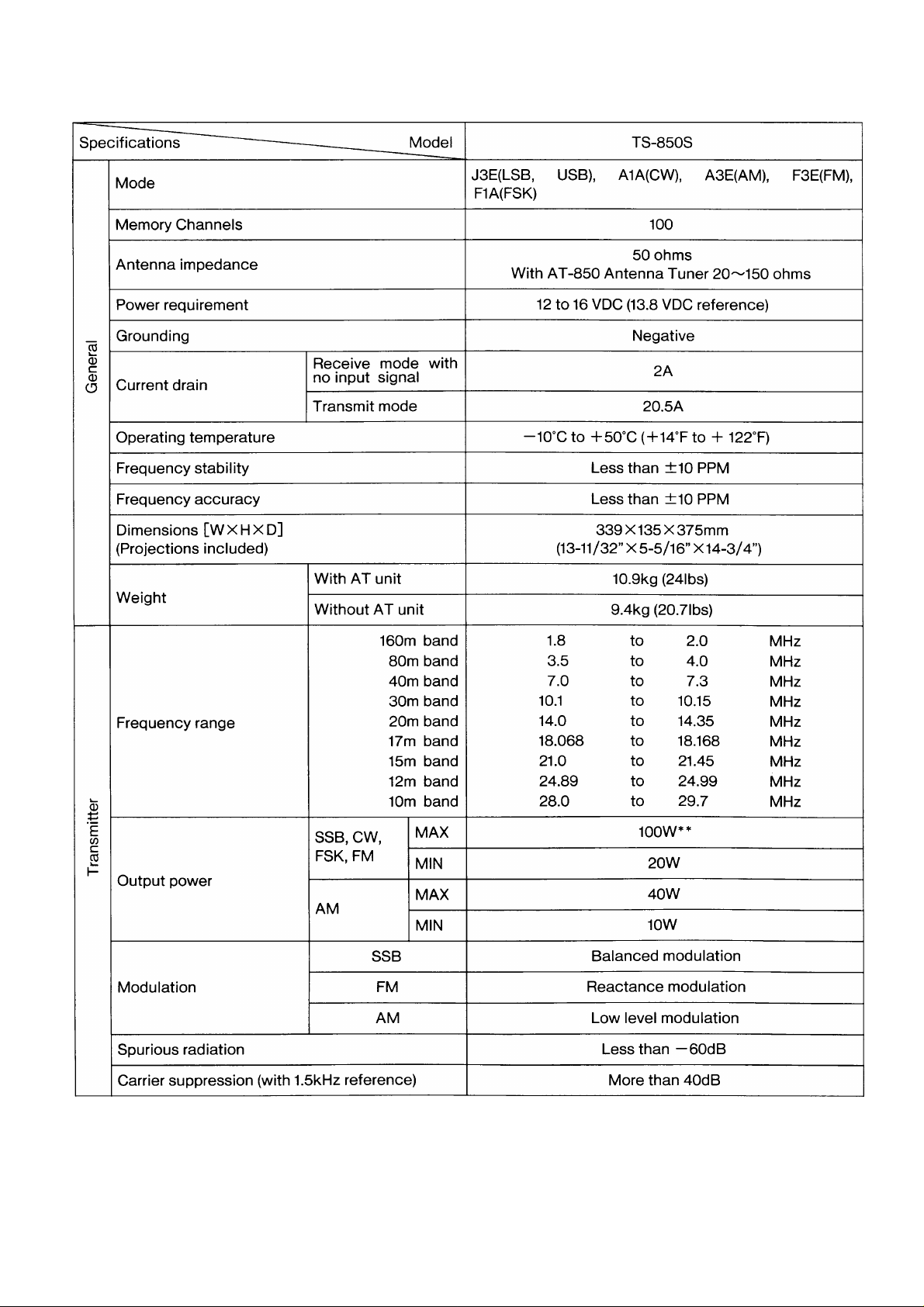
2-1. SPECIFICATIONS
Page 5

Specifications
----
Model
TS-850S
CT3
Unwanted sideband suppression (with 1.5kHz
reference)
Maximum frequency deviation (FM)
o
E
Frequency response (—6dB)
CO
I-
Ai 1 vanaoie range
10 Hz step
20 Hz step
Less than ±5kHz
More than ±1.2kHz
More than ±2.4kHz
Microphone impedance 600n
Circuitry
Frequency range
Intermediate frequency
SSB, CW,
FSK
(at lOdB S
100kHz~500kHz
500kHz~1.62MHz*
*1.62MHz~24.5MHz
Triple conversion superheterodyne
100kHz to 30MHz
1st; 73.05MHz, 2nd : 8.83MHz, 3rd : 455kHz
Less than 0.2 //V
Less than 0.2 pc\/
+ N/N)
Sensitivity
AM
24.5MHz~30MHz
100kHz~500kHz Less than 2 //V
500kHz~1.62MHz* Less than 32 /^V
Less than 0.13 //V
(at lOdB S
+ N/N)
*1.62MHz~24.5MHz
More than 40dB
400 to 2600Hz
Less than 4 //V
Less than 2
0)
>
■(D
O
CD
CC
Selectivity
Image ratio
1st IF rejection
Notch filter attenuation
HM vanaoie range
Squelch
sensitivity
Output
FM
(at12dBSINAD)
SSB, CW,
FSK, AM
FM
24.5MHz~30MHz Less than 1.3//V
28MHz~30MHz
SSB, CW, FSK
AM
Less than 0.25 //V
-6dB:2.4kHz, -60dB:3.8kHz
-6dB:6kHz, -60dB;15kHz
FM -6dB:12kHz, -60dB:24kHz
More than 80dB
More than 80dB
More than 40dB
10 Hz step
20 Hz step
100kHz~500kHz
500kHz~1.62MHz*
♦1.62MHz~30MHz
28MHz~30MHz
More than ±1.2kHz
More than ± 2.4kHz
Less than 2 //V
Less than 20 /uV
Less than 2 ;c^V
Less than 0.25 //V
1.5W across 8 ohms load (10% distortion)
Output load impedance
8 ohms
Notes
1. Circuit and ratings are subject to change without notice due to advancements in technology.
2. Remember to keep the transmit output power within the power limitations of your license.
3. *: The U.S.A. version is 1.705 MHz.
4. **: With auto antenna tuner in “THRU” or bypass position.
Page 6

2-2. ACCESSORIES
Unpack your TS-850S carefully and confirm that it is supplied with the following accessories.
Dynamic microphone
DIN plug (7-pin) ................................................................E07-0751-05
DIN plug (13-pin) ..............................................................E07-1351-05
DC power cable assembly
Calibration cable
Fuse (25A)
Fuse (3A)
External control Instruction Manual
Instruction Manual ................................................................B62-0061-XX ...........................1 copy
Warranty card (U.S.A., Canada and Europe version only) ........................................................1 ea.
After unpacking
Shipping container:
Save the boxes and packing in the event your unit needs to be transported for remote operation, maintenance,
or service.
...........................................................................
.............................................................................
...........................................................
...................................................
..................................................................
.....................................
T91-0352-15
E30-3035-05 ................................1 ea.
E31-2154-05
F51-0011-05
F06-3026-05 ................................1 ea.
B62-0065-XX ...........................1 copy
.............................
...............................
.............................
.............................
.............................
1 ea.
lea.
1 ea.
lea.
lea.
Page 7
3. INSTALLATION AND CONNECTION
3-1. INSTALLATION
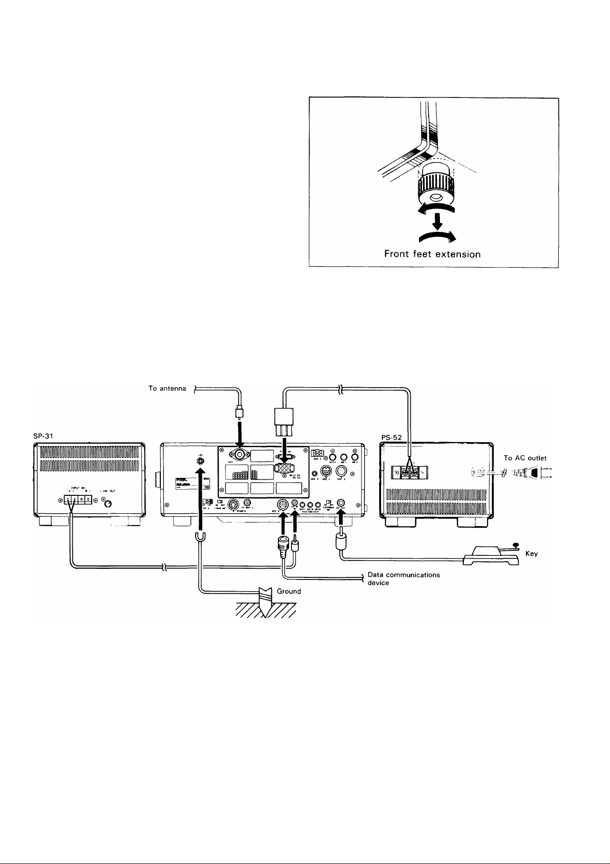
■FRONT FEET
By extending the front feet, the front panel can be
elevated for operating convenience.
Turn the front foot left and pull down.
Then turn right to lock.
3-2. CONNECTION
The TS-850S requires more than 20.5 A at 13.8 VDC
when transmitting at full power. Use the PS-52 power
supply for fixed station operation.
A. Rear Panel
Page 8

(1) Antenna (4) Key connection
Caution
Protect your equipment — Use a LIGHTNING
ARRESTER.
The type of antenna that is used will greatly affect
the performance of the transceiver. Use a properly
adjusted antenna, of good quality, to enable your
transceiver to perform at its best. The antenna input
impedance is 50 ohms. Use 50-ohm coaxial cable
such as 5D-2V or RG-213/U (RG-8A/U) for this
connection. If the antenna is far from the transceiver
the use of low loss coaxial cable, such as 5D-2V or
RG-213/U (RG-8A/U) are recommended. Match the
impedance of the coaxial cable and that of the
antenna so that the SWR is less than 1.5 to 1. The
protection circuit in the transceiver will activate if the
SWR is particularly poor (greater than 3 to 1). High
SWR value will cause transmitter output to drop, and
may lead to TVI or BCI reports.
(2) Grounding
Caution
Never use a gas pipe or electrical conduit pipe.
Notes
1. A ground connection that is a 1/4 wavelength or
its multiple may provide a good DC ground, but
it will not provide a good RF ground.
2. A city water pipe cannot be used as a good
earth in some cases.
Your key should be connected as illustrated in the
figure below. When using an electronic keyer, make
sure that polarity is set for positive. Always use
shielded line from the key to transceiver, (diameter
6.0 mm)
|To use external straight key
+5V, Contact
Current about 1
mA
Ground Not used +
or
Ground +
Note
Check the polarity of the plug when you use an
electronic keyer.
Please refer to Section 4-4.
-I-5V, Contact
Current about 1
mA
Making a good earth connection is important for
preventing dangers such as electric shock and for
emitting a high quality signal with minimum spurious
radiation. Bury a commercially available ground rod
or copper plate under the ground and connect it to
the GND terminal. A thick wire, cut as short as
possible, should be used for the connection. To
make a good earth connection, connect the GND
terminal to a grounded metal water pipe.
(3) External speaker
The TS-850S includes a built-in speaker. If you
would like to use an external speaker, such as the
SP-31, it may be connected to the EXT SP jack on
the rear of the transceiver. The speaker may be any
good 8 ohm permanent magnet type speaker. The
diameter should be at least 4 inches for good audio
quality. If you plan on using a speaker other than the
SP-31 it should be equipped with a miniature phone
jack plug, (diameter 3.5 mm)
8
Page 9
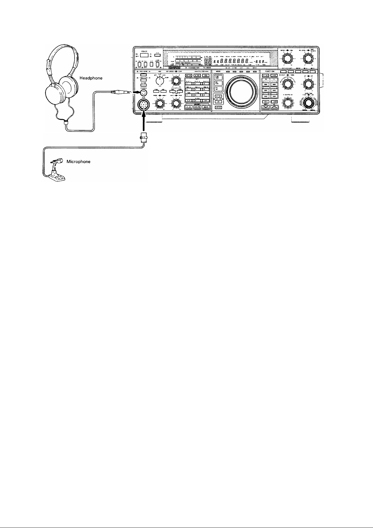
B. Front Panel
(1) Headphones
Any low-impedance (4-16 ohms) headphone may be
used with the transceiver. Connect the headphones
to the front panel PHONES jack, (diameter 6.0 mm).
The optional HS-5 or HS-6 headphones are best
suited for use with the transceiver. Stereo type
headphones can also be used.
(2) Microphones
Any microphone with an impedance to 6000 may be
used with this transceiver. The KENWOOD
microphones MC-43S (handheld), MC-60A, MC-80,
MC-85 (table-top type) are recom-mended.
Page 10
4. OPERATION
4-1. OPERATING CONTROLS 4-1-1. Front Panel
P.10
I I: cb
L vox A FULL AlP eOO$T.a
□ □ □ □
HIGH
GCDOocoooaaooooocooaocooacxxxic
-J_—1-
«OOOyCIOr>y>OO^yiOOOOOO^^^ I gTf ] riiS~]
KBNKXX3 Hf TBAWScetVEB TS-850S
.. .. . rmnn
P.12 P.13
ri»HTtn
P.11
PPO SCAN
a tt
Lse USB cv-R
Note
All segments on the Display Panel and Indicators
are shown on for this explanation.
P.12
NOTCH SQL NB LEVEL •
i .H. -a a a.H.
P.14
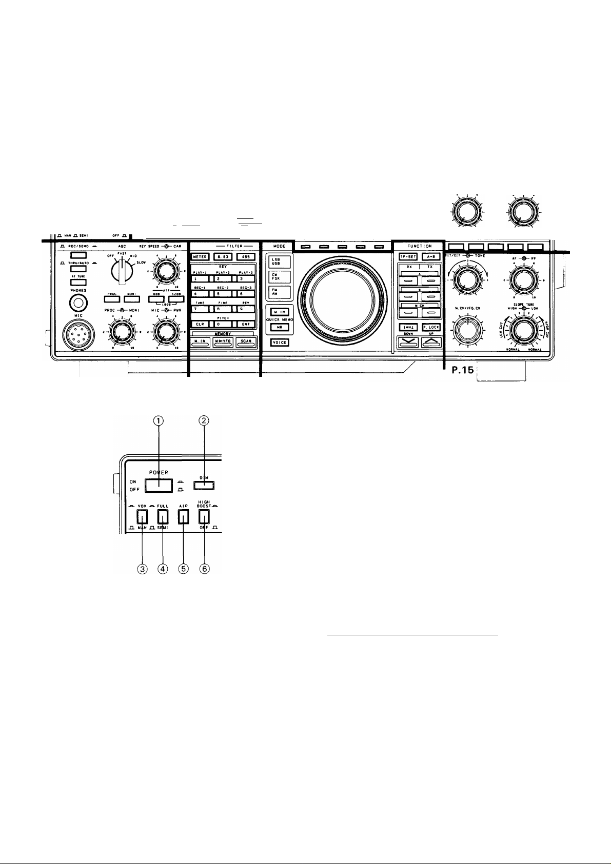
© POWER switch
Press to turn the power ON or OFF.
@ DIM (Dimmer) switch
Selects the intensity of both the digital display and
the meter illumination, bright or dim.
©VOX/MAN switch
VOX (Voice Operated Switch) operation is possible
in SSB, AM or FM operations. Break-in operation is
possible in CW operation. To activate the VOX
circuitry place the VOX switch ON(a).
0FULL/SEMI (Break-in) switch
This switch affects the transmit/receive recovery
time. In the SEMI position the transceiver will key
when the key is depressed and remain in the
transmit position until a preset delay has been
reached. In the FULL position the transceiver will
return to receive as soon as the key is released,
thus allowing you to copy incoming signals between
characters.
® AlP (Advanced Intercept Point) switch
Use AlP when good signal reception can not be
obtained. When switched on, it reduces interference
from strong signals.
When the frequency falls below 9.5 MHz,
initialization takes place automatically.
____________
Note
When AlP is on, the sensitivity of the receiver is
reduced about 10 dB.
©HIGH BOOST switch
The high-frequencies of the transmit audio signal are
emphasized. Intelligibility may be improved,
depending on the characteristics of the microphone
and atmospheric conditions.
10
Page 11
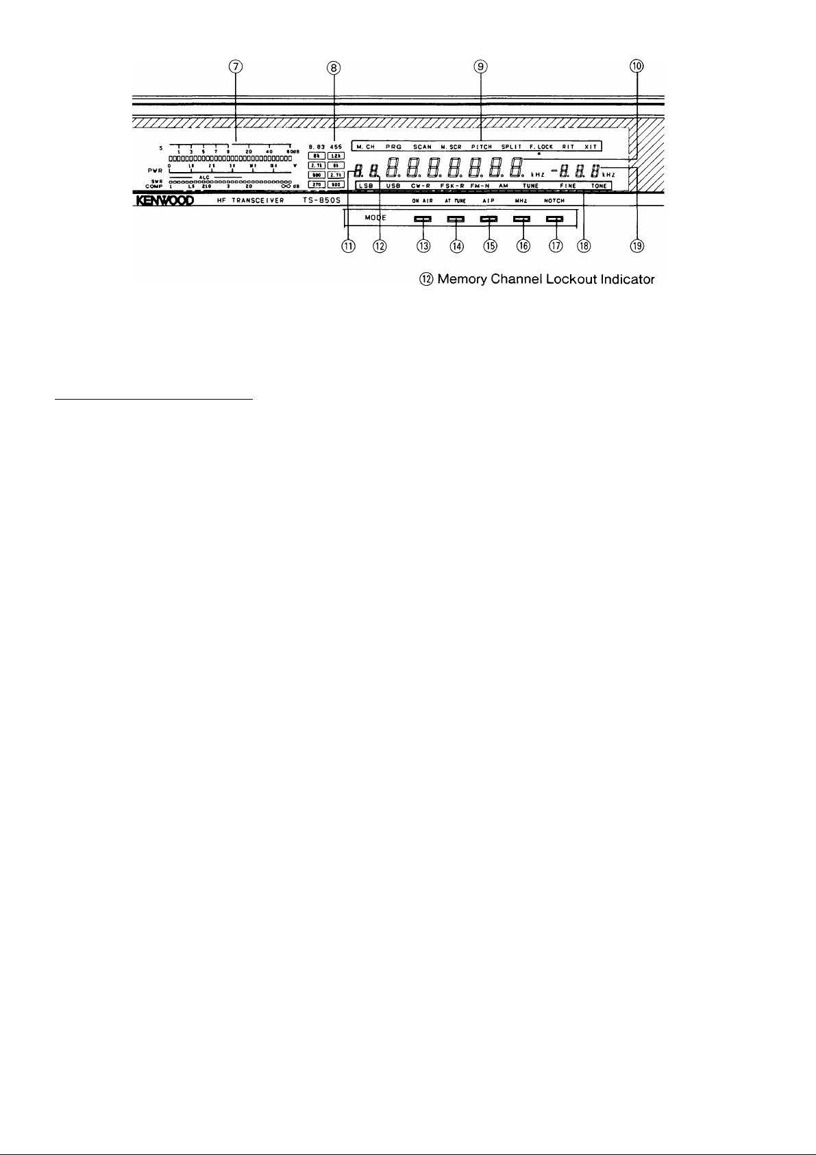
@ Meter
During receive the meter is used as an S-meter.
During transmit the meter is used as a POWER
meter, and is controlled by the METER key, and
provides either VSWR, COMP level or ALC level
readings.
The meter can be used as a peak hold meter.
Please refer to Section 4-10-15.)
________________
Note
One or two segments of the S meter may light
when there is no signal, due to atmospheric noise.
The • display indicates the Memory Channel
currently in the display will be skipped during
Memory Channel scan.
(§)ON AIR indicator
Lights during transmit.
(@ AT TUNE (Antenna Tuner) indicator
Lights to show that the automatic antenna tuner is in
operation. Do not attempt to operate further until it
goes off.
(8) Filter indicators
Indicates which filters have been selected.
(9) M.CH (Memory channel) display
Turns ON during a Memory Channel operation.
PRO (Program) display
Lights during selection or operation on memory
channels 90 to 99.
SCAN display
Turns ON during scanning.
M.SCR (Memory scroll) display
Lights when the M.IN key is pressed. When the
memory scroll function is active you can review
the contents of the memory channels without a
loss of the incoming receive frequency.
PITCH display
Lights when the PITCH function is ON.
SPLIT display
Turns ON during split operation.
F.LOCK display
Lights when the F.LOCK key is ON.
RIT display
Turns ON when using RIT.
XIT display
Turns ON when using XIT.
(10) Frequency display
Indicates the operating frequency. The 10 Hz digit
may be suppressed. (Please refer to Section 4-10-
15.)
(i])Memory Channel number display
Memory Channel Number is displayed.
(g) AIP(Advanced Intercept Point) indicator
Lights when the AlP switch is ON.
(@MHz indicator
Lights when the 1 MHz key is ON.
(17) NOTCH indicator
Lights when the NOTCH switch is ON.
(i|) LSB indicator
Indicates the LSB has been selected.
USB indicator
Indicates the USB has been selected.
CW indicator
Indicates the CW has been selected.
CW-R indicator
Indicates the CW-R(Reverse) has been selected.
FSK indicator
Indicates the FSK has been selected.
FSK-R indicator
Indicates the FSK-R(Reverse) has been
selected.
FM indicator
Indicates the FM has been selected.
FM-N indicator
Indicates the FM-N(narrow) has been selected.
AM indicator
Indicates the AM has been selected.
TUNE indicator
Indicates the TUNE has been selected.
FINE indicator
Indicates the FINE tuning has been selected.
TONE indicator
Indicates the TONE function has been selected.
11
Page 12
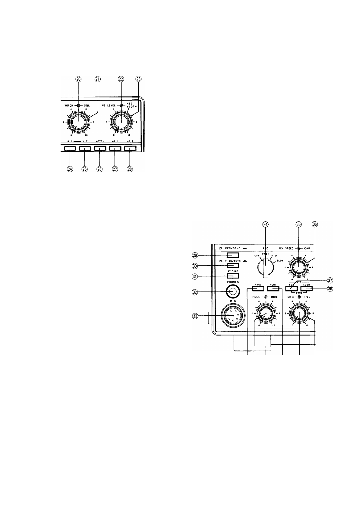
(i|) RIT/XIT frequency display
Shows the amount of RIT/XIT offset to the nearest
10 Hz. Minus “ —” appears in the display when the
RIT / XIT offset is below the transmit / receive
frequency.
Shows the scan speed during scanning.
@ NOTCH control
The NOTCH function is used to reduce or eliminate
heterodyne, or CW type signals. The NOTCH filter
will not be effective against SSB, AM or FM type
signals.
Note
This switch is disabled during FM operation.
@NB 1 switch
For pulse type noise, such as generated by
automotive ignition systems, turn the NB 1 switch
ON.
This switch will not help to eliminate atmospheric or
line noises, only pulse type noise.
(^ NB 2 switch
Noise blanker 2 is used for long duration pulse
noise, like the “woodpecker”. To reduce
“woodpecker” radar noise interference, set switch
NB 2 to the ON position (NB 2’s effectiveness
depends on the specific type of interference). If you
use NB 2 for short duration pulse noise, the receive
signal may become distorted, making it difficult to
hear.
Unfortunately no noise blanker can remove all
different types of interference; but the two noise
blankers that have been provided in the TS-850 are
effective in most cases.
If there is no “woodpecker” present, the switch
should be in the OFF position.
@ SQL (Squelch) control
This control is used to eliminate atmospheric noise,
and receiver static noise during no signal periods.
Slowly rotate the control clockwise to the point
where the ambient noise just disappears, and the
speaker shuts off. This point is known as the
squelch threshold point. Now you will only hear
output from the speaker when an incoming signal is
present. For weak signal reception this control
should be fully counterclockwise.
@ NB LEVEL control
Controls the noise blanker operating level.
Use only the minimum level necessary.
(§) NB2 WIDTH control
This control varies the width of the blanking pulse of
NB2.
Notes
1. The NB2 control only works on woodpecker
type noise.
2. If the control is turned too far, the received
signal may be distorted. Set the control for the
best receive signal.
(24) RIT switch
Press to turn the RIT ON or OFF.
@XIT switch
Press to turn the XIT ON or OFF.
® @ ® 0
(§) REC/SEND switch
This switch is used when you want to manually
control transmit or receive.
REC : Places the transceiver into receive.
SEND : Places the transceiver into transmit.
(§)THRU/AUTO switch
THRU : The auto antenna tuner is not used in
transmit.
AUTO: The auto antenna tuner is used in transmit.
(§) NOTCH switch
When this switch is ON, the notch filter is activated.
12
0 AT TUNE switch
When this switch is tuned ON and the THRU/AUTO
switch is placed in the AUTO position, the automatic
Page 13
tuner will be engaged and the tuner will try to match
the antenna.
©PHONES jack
Output terminal for headphones.
©MIC jack
Microphone connection.
GND (MIC)
<D NC
© PROC (Processor) switch
Effective transmit power output will increase when
the PROC switch is turned ON during SSB mode
operations.
© PROC (Processor) control
Adjust the PROC control while speaking into the
microphone in a normal tone of voice, for a peak
COMP scale reading of no more than 10 dB. Do not
overdrive the COMPRESSOR.
Over driving the compressor will deteriorate voice
quality, increase transmitter noise level, and in
general make copying your signal more difficult.
8 V/approx. 10 mA
MIC connector (Front view)
©AGO switch
This switch selects the operating time constant of
the AGO (Automatic Gain Control) circuit. When the
AGC switch is set to SLOW, the receiver gain and
S-meter readings will react slowly to large input
changes, and when set to FAST, the receiver gain
and S-meter will react quickly to changes in the
input signal level.
The normal position when using all modes is the
SLOW position. When working any of the following
you might wish to use the FAST position.
• When tuning rapidly, use the FAST position.
• When receiving weak signals.
• When a high-speed CW signal is being received.
Note
This switch is disabled during FM operation.
© KEY SPEED control
This controls the speed of the electronic keyer. Turn
the knob clockwise to increase speed.
©MONI (Monitor) control
This controls the volume of the transmit monitor.
This control is operational in the SSB and FSK
mode.
® MONI (Monitor) switch
Allows monitoring of your transmit signal.
This control is operational in the SSB and FSK
mode.
® MIC gain control
Microphone gain can be adjusted during SSB and
AM operations. Gain is increased by turning the
control clockwise.
(© PWR (Power) control
Power can be controlled in all modes. Power is
increased by turning the control clockwise.
Keep the transmit power within the output power
limits of your license.
© ®
©CAR (Carrier level) control
Used to adjust carrier level during CW, AM and FSK.
©6dB ATT (Attenuator) switch
The incoming receive signal level is attenuated by
approximately 6 dB when this switch is activated.
©12dB ATT (Attenuator) switch
The incoming receive signal level is attenuated by
approximately 12 dB when this switch is activated.
The incoming receive signal level is attenuated by
approximately 18 dB when both the 6 dB switch and
12 dB switch are activated.
This control is also useful when a strong signal is
near your desired signal; while some loss will occur
to the desired signal, as well as the undesired signal,
the use of the attenuator will sometimes allow you to
understand what is being received. For normal
receiver performance, this switch should be in the
OFF position.
METER I I 8. ^3
I I
® METER key
The meter function can be changed as follows
during transmission.
13
Page 14
r*“ SWR---------► ALC
------
► COMP
(The PROC switch
is ON when
the SSB mode.)
■No in(dicator<-
SWR : Indicates voltage standing wave ratio
(VSWR).
ALC : Indicates internal ALC voltage, or the ALC
voltage fed back from a linear amplifier
connected to this transceiver.
COMP: Indicates compression level during speech
processor operations. Do not exceed 10 dB
of compression. The PROC switch is ON
when the SSB mode.
(§)8.83 FILTER key
Selects the desired 8.83MHz filter regardless of
mode.
@455 FILTER key
Selects the desired 455kHz filter regardless of
mode.
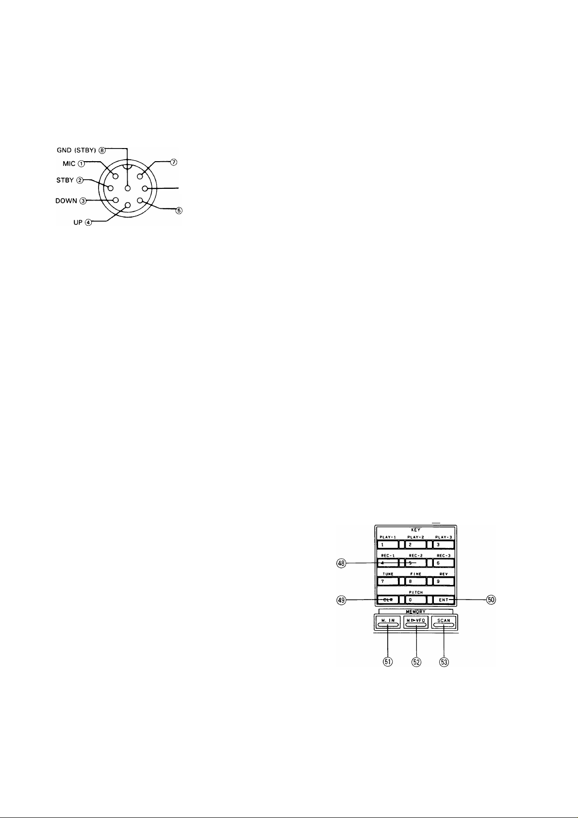
@ Numeric keypad
Consists of a series of switches which will be used
to set, turn on and/or turn off functions.
When used in conjunction with the ENT key, the
keypad is used to directly enter a frequency.
When used in conjunction with the M.IN key, the
keypad is used to enter data into a memory channel.
PLAY, REC key
Used to record and play voice or CW messages
for transmission. (The optional DRU-2 digital
recording unit is required.)
TUNE key
Sets the transmit power to half the rated power
regardless of the position of the PWR control.
Outputs a zero beat in CW receive mode. This
key is useful when tuning a linear amplifier.
FINE key
Makes one turn of the tuning knob equal 1 kHz (1
Hz step) to facilitate precise tuning. When the key
is pressed again, normal tuning returns.
REV key
The BFO uses USB for normal CW reception.
With this key, reception becomes possible on
LSB. The BFO uses LSB for normal FSK
operation. With this key, reception becomes
possible on USB. By pressing this key, reverse
shift is also used for transmission.
PITCH key
Press to turn the PITCH function ON or OFF.
@ CLR (Clear) key
Used when reentering memory channel data, erasing
a memory channel, clearing scan, or when
specifying the channels that will be skipped during
scan operations.
@ M.IN key
Used to enter data into a memory channel.
@M^VFO key
Used to transfer
a frequency from memory to the
VFO.
(§)SCAN key
Pressing during VFO operation will initiate program
scan, and pressing during memory operation will
initiate memory scan.
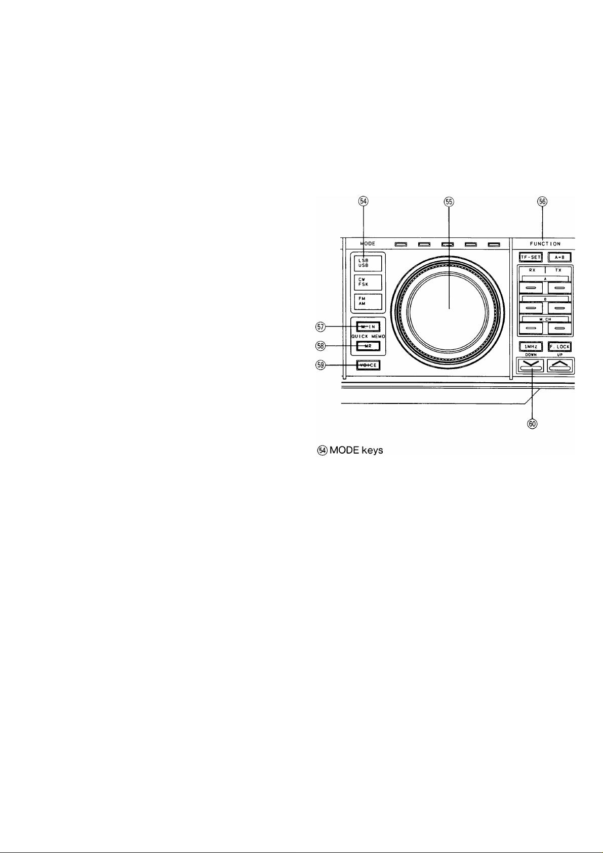
These keys are used to select the desired mode of
operation. When a MODE key is pressed the first
character of that mode will be sounded in Morse
code thru the internal speaker.
LSB/USB key
Press the LSB/USB key to alternate between LSB
and USB mode.
CW/FSK key
Press the CW/FSK key to alternate between CW
(R) and FSK(R) mode.
FM/AM key
Press the FM/AM key to alternate between FM(N)
and AM mode.
(§) TUNING knob (VFO)
Rotate the knob to select the desired frequency.
Fast tuning is possible by rotating the knob rapidly.
The dial drag is adjustable by holding the outside
knob and turning the inside knob clockwise to
increase drag, and counterclockwise to decrease
drag.
(50) ENT (Enter) key
Used to directly enter a frequency from the numeric
keypad.
14
Page 15
TF-SET key
Depressing this key will allow you to rapidly set
or check the transmit frequency, during SPLIT
operations, without the need of actually
transmitting.
A = B key
Equalizes the frequencies, modes and filter
selection of VFO A and VFO B.
A (VFO A) key
RX ; Press this key to receive signals on VFO A.
TX : Press this key to transmit signals on VFO A.
B (VFO B) key
RX ; Press this key to receive signals on VFO B.
TX : Press this key to transmit signals on VFO B.
M.CH (Memory Channel) key
RX: Press this key to receive signals on the
memory channel.
TX: Press this key to transmit signals on the
memory channel.
Note
When just an RX key (VFO A, VFO B, or M.CH.) is
pressed, the same VFO or memory channel is
used for both reception and transmission. For split
operation, select VFO A or VFO B for reception,
and, for transmission, either select the other VFO
or select TX M.CH.
1MHz key
This key is used to determine if the UP/DOWN
switches will function in 1 MHz steps or only
thru the amateur bands. When the 1 MHz step
position is selected, the MHz indicator will light.
F.LOCK key
The selected dial frequency and mode are
locked.
_________________________________
Note
When the F.LOCK key is on the TF-SET,
FILTER, METER, VOICE keys, AlP, RIT, XIT
switches and RIT/XIT control are still active.
(g)QUICK MEMO M.IN key
This key writes data to the quick memory.
(§) VOICE key
Press this key to activate the optional voice
synthesizer unit VS-2.
(§) UP/DOWN switch
Pressing the UP switch increases the frequency,
and pressing the DOWN switch decreases it.
When the function setting at power on is on, this
switch changes the setting.
RlT/XIT —TONE
(g) RIT/XIT control
RIT (Receiver Incremental Tuning)
The RIT control allows shifting the receiver
frequency. Use of the RIT control will not affect
the transmit frequency.
When the RIT switch is ON, the RIT indicator
will light, and the receive frequency can be
adjusted by using the RIT control.
Note
When the RIT is ON the transmit frequency
may be different from the receive frequency.
For normal operation leave the RIT switch
OFF. It should be used only when necessary.
The scan speed can be changed during scanning
with the RIT control.
XIT (Transmitter Incremental Tuning)
XIT is very similar to RIT. XIT is only active in
the transmit mode. By using the XIT function it is
possible to offset the transmit frequency without
the normal loss of receiver audio that is
experienced when using the SPLIT function.
The RIT / XIT offset can be preset, without
affecting the actual operating frequency by
turning OFF the RIT/XIT and using the RIT/XIT
display to determine the offset.
This is useful when working a DX station who is
“split” within the XIT range.
The RIT / XIT step size is either 10 Hz or 20 Hz.
Please refer to Section 4-10-15 for information on
how to select the desired step size.
@QUICKMEMOMRkey
This key recalls the quick memory.
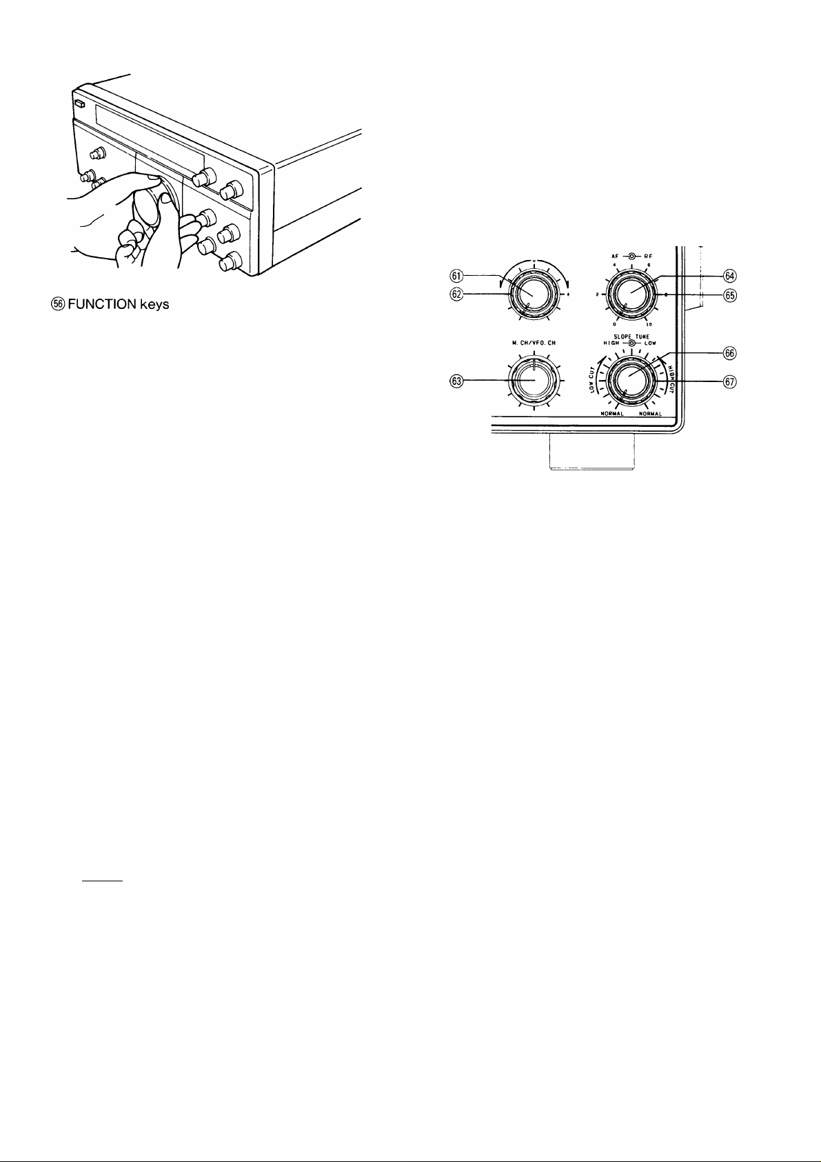
@TONE control
Turn the control to increase or decrease the receiver
audio tone.
15
Page 16
The standard position is with the control turned fully
clockwise. As the control is turned counterclockwise,
high frequencies are cut.
(§)M.CH/VFO CH control
This control is used to select the desired memory
channel during Memory Channel Operation.
This control is also used to change the frequency in
10 kHz steps during VFO operations.
The control is also used to select the desired power
on function you wish to change. See section 4-10-
15.
(g)AF gain control
Turn the knob to increase or decrease the volume.
Clockwise rotation increases the volume and
counterclockwise rotation decreases the volume.
Note
The output level of the “Beep” and “Sidetone” are
not affected by adjusting of the AF gain control.
(§)RF gain control
This control adjusts the gain of the receiver highfrequency amplifier section.
For normal receiver performance, and maximum
gain, this control should be all the way to the right. If
you are having trouble copying the desired signal
make a note of the stations peak S-meter reading.
Then, adjust the RF gain control left, so that the
meter needle is stationary at this level. Now, all
signals that were less than the desired signal will be
attenuated, such as static noise, etc., making
reception easier.
If the incoming signal pegs the S-meter you can also
reduce the receiver gain by moving the RF gain
control to the left. The S-meter pointer will always
advance up-scale as the RF gain control is moved,
to indicate that the gain has been reduced.
(g) SLOPE TUNE LOW CUT control
Adjust the LOW CUT control clockwise, and
interference from signals lower than the operating
frequency will be reduced. As with the HIGH CUT
control, use of the LOW CUT control will also affect
the audio frequency passband. In this case the low
frequency components of the audio signal will be
reduced.
Note
This control is disabled during FM operation.
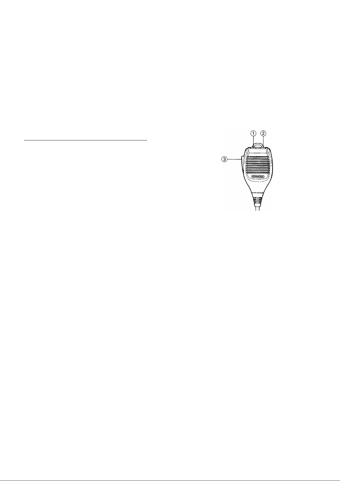
IMicrophone
©(2)UP/DWN(Up/Down) switches
These switches are used to step the VFO frequency
or memory channel up and down. The frequency will
change continuously if the switches are pressed and
held.
(3)PTT (Push To Talk) switch
The transceiver will be placed
whenever this switch is pressed.
into Transmit
Simultaneous use of the RF gain control and AGC
switch
If a strong signal (such as a local station) appears in
the vicinity of the intended receive signal, the S-
meter may show unusual deflection due to the AGC
voltage developed from the strong disturbing signal.
If this occurs, move the RF gain control to the left so
the meter pointer remains at about the original
deflection peak and turn the AGC switch to the
FAST position. This will reduce the unwanted AGC
voltage and permit clear reception.
Note
This control is disabled during FM operation.
(§)SLOPE TUNE HIGH CUT control
Adjust the HIGH CUT control counterclockwise, and
interference from signals higher than the operating
frequency will be reduced. The high-frequency
components of the resulting receiver audio will also
be reduced.
Note
This control is disabled during FM operation.
16
Page 17
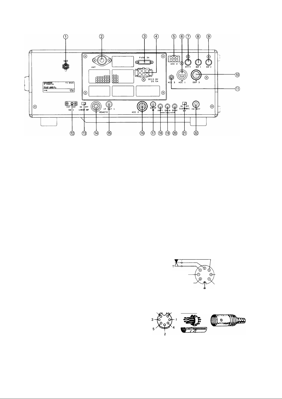
4-1-2. Rear Panel
©GND (Ground) terminal
To prevent electric shock, as well as RFI and BCl,
connect the transceiver to a good earth ground.
(D ANT (Antenna) connector
This connector should be attached to a suitable
antenna for transmitting and receiving. The antenna
cable should be 50-ohm coax, terminated with a PL259 connector.
©FUSE
Power fuse for the ACC 4 connector.
@ DC power connector
This is used to connect the DC power supply.
© ACC 4 connector
The optional AT-300 may be connected here.
©ACC 1 connector
The optional DSP-100 or the optional IF-232C is
connected here.
© RTTY terminal
For connection to an RTTY interface unit, (direct
FSK keying) The terminal is equipped the short pin
plug for the factory.
©DSP 1 terminal
The optional DSP-100 is connected here.
©ACC 3 terminal
This is used to connect the remote controller.
® SW1 switch
This transceiver has a cover on the back to protect
against misoperation. To connect the external
antenna tuner to this unit, remove the cover and
slide switch SW1 to EXT. The built-in antenna tuner
will then not operate.
© LINEAR AMP switch
Activates the internal keying relay for linear amplifier
control.
© REMOTE connector
This connector is used when a linear amplifier is
used.
Control relay p
Speaker output
ALC input
GND'
From standby switch
(PTT circuit for foot switch)
+ 12 VDC ON transmit
max. 10 mA
Internal wiring
View from cord
7. ^ 6
aaa—w-
® DSP 2 terminal
The optional DSP-100 is connected here.
(© DSP 3 connector
The optional DSP-100 is connected here.
© IF OUT 1 terminal
This terminal is for the band scope of the station
monitor.
IF 1 is for connection to the SM-230 for Pan Display.
(8.83 MHz)
17
Page 18

0|) ACC 2 connector
Terminal numbers and their applications are as
follows :
ACC2 pin assignments
Pin number
Symbol
Use
© © ©©'^
0©0
.0 0©©;
13-pin DIN plug (E07-1351-05)
ACC2 pin assignments
Pin number
1 NO
2
3
4
Symbol Use
NO
ANO
GND Grounding (The shielded wire
©
View from the
©
nrmrrmwy.
No connection
No connection
The receiver audio at a fixed
level independent of AF gain
control setting. Output
voltage : 300 mV / 4.7ki2 or
more at high input level
of the audio output terminal
is connected here.)
rear panel.
11
12
13 SS Standby terminal.
® EXT SP (External speaker) jack
This jack is for connection of an external speaker.
® ANTI control
VOX operations are sometimes difficult with high
speaker volume control settings. The ANTI control is
used to reduce the tendency of the VOX to activate
from inputs from the speaker. The ANTI control is
not active when headphones are connected.
(19) GAIN control
This control adjusts the sensitivity of VOX amplifier.
Adjust this control for your personal preference.
(§) DELAY control
This control adjusts how long the transceiver will
remain keyed after voice input has stopped.
PKD
GND
This is the MIC (microphone)
input pin from the terminal
unit. The input level is
approximately 20 mV.
Grounding (The shielded wire
of the audio output terminal
is connected here.)
Grounding transmits.
5
6
7
8
9
PSQ
Output
voltage
pin for
S-meter.
NO No connection
GND
PKS
This pin is used for
connecting a TNG (Terminal
Node Controller) for use with
packet radio. It is the
Squelch Control terminal and
will not allow packet
communications while
squelch is off.
Output voltage varies with Smeter indication.
Grounding
This is the standby pin used
exclusively for the terminal
unit. When this pin is in use
for standby, the microphone
input is automatically shut off
and the transmit is
operational.
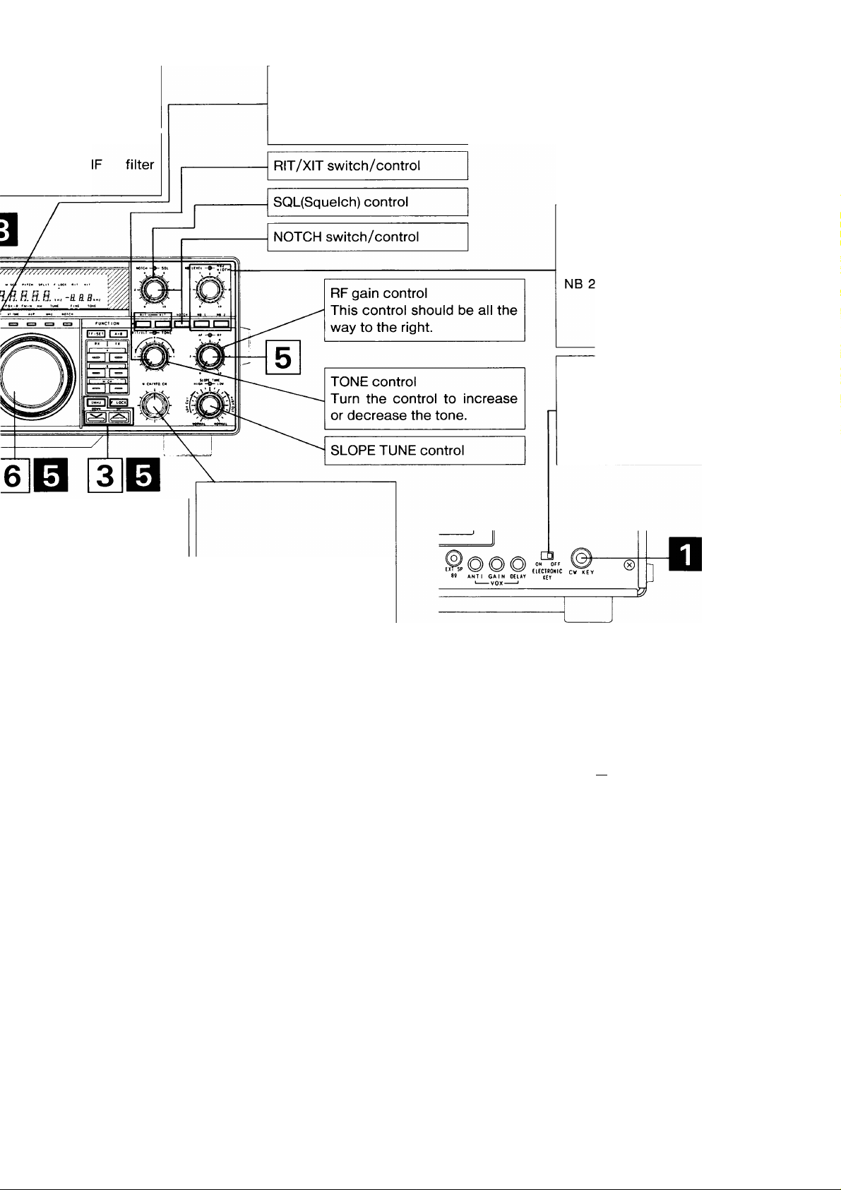
(g) ELECTRONIC KEY switch
Turns the electronic keyer on or off. Turn the switch
off when CW is initiated by a straight key or when
using an external electronic keyer.
@ CW KEY jack
Using shielded line, connect a 6.0mm diameter
phone plug to this jack for CW operation. Connect a
paddle type key to the key jack use a 6.0mm
diameter stereo plug. Open-terminal voltage is
approximately 5 VDC. (See Section 4-4 for additional
key information.)
18
10
NO
No connection
Page 19
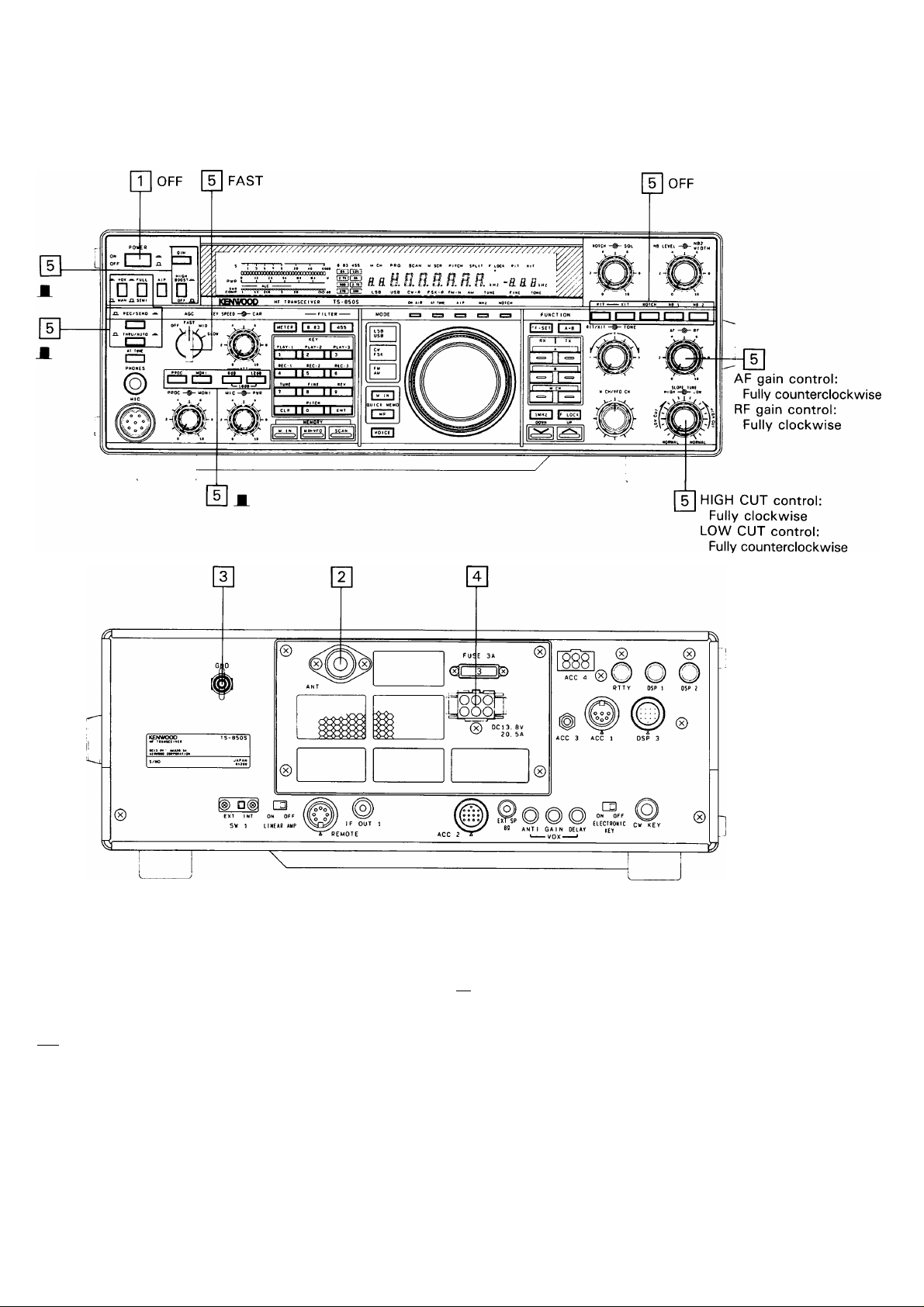
4-2. INITIAL SETTING
Prior to operation ensure the following switches and
controls are set as indicated in the figure below:
pT| Ensure the POWER switch is OFF.
[Y] An antenna must be connected.
Caution
Never transmit without the antenna connected.
3 A ground must be connected.
[4] The DC power cable is connected.
Ensure the front panel controls and switches are
set as shown in the figures above.
Page 20
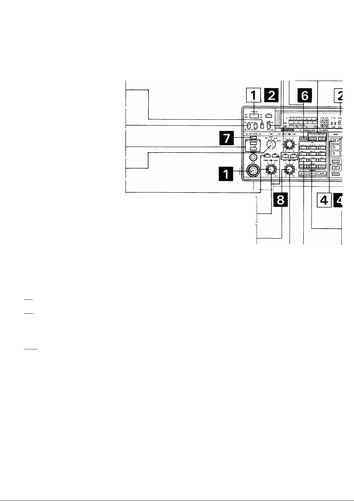
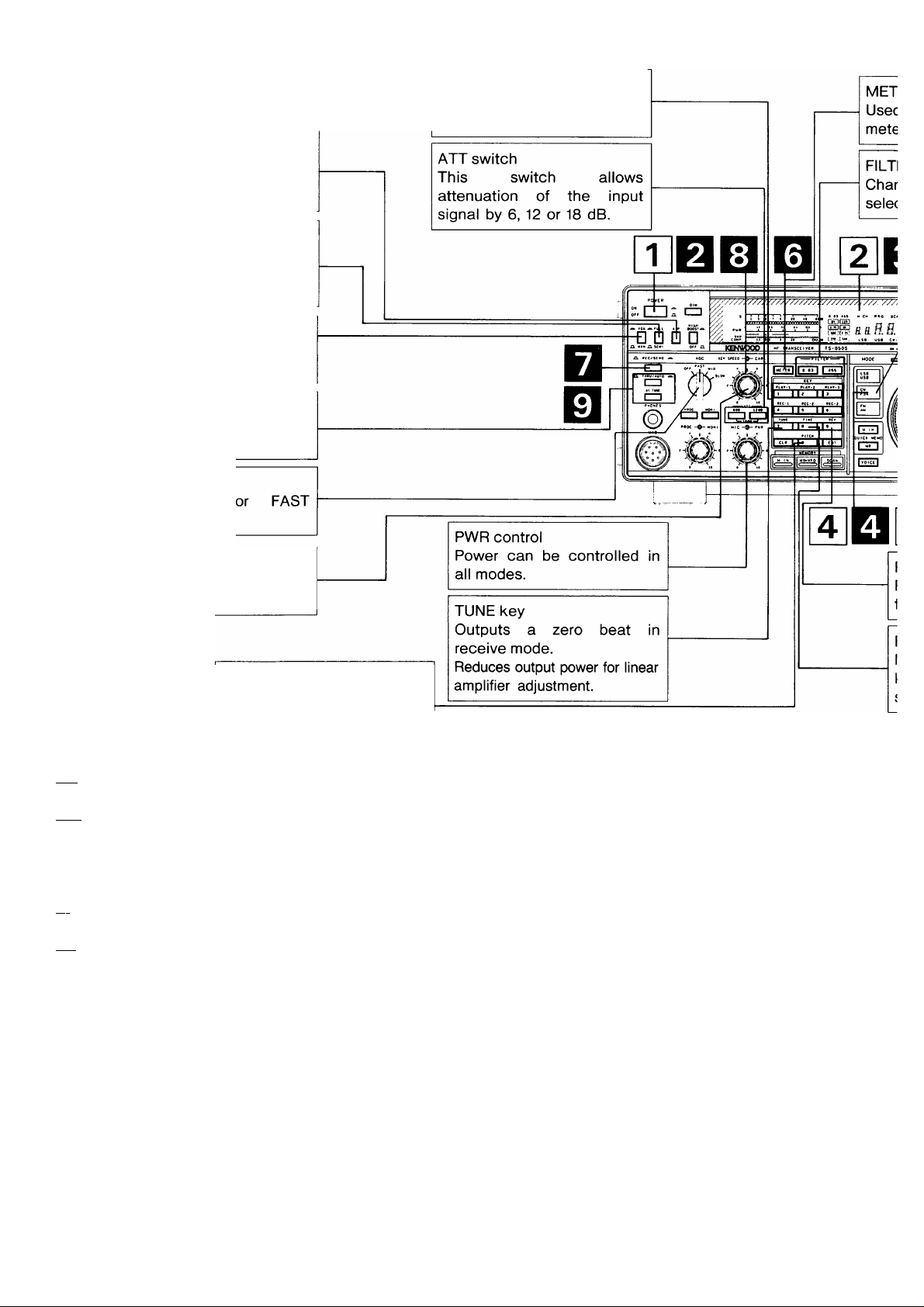
4-3. SSB OPERATION
ATT switch
This switch allows attenuation of the
input signal by 6, 12 or 18 dB.
METER key
Used to select
meter function in
AlP switch
When switched on, it
reduces interference from
strong signals.
VOX/MAN switch
Used to operate VOX.
THRU/AUTO switch
THRU: Antenna tuner is off.
AUTO: Antenna tuner is on.
AGO switch
Set to SLOW.
PROC switch/control
Used to actuate the speech
processor circuit.
PWR control
Power can be controlled in
all modes.
HIGH BOOST switch
The high-frequencies of the transmit
audio signal are emphasized.
MONI switch/control
Allows monitoring of your
transmit signal.
MIC gain control
Microphone gain can be
adjusted during operation.
FILTER key
Changes the
selectivity.
(RECEIVING)
pT| Turn on the DC power supply and then turn the transceiver’s power switch ON.
|~2] A frequency is shown in the display.
3~| Press the UP/DOWN switches to select the desired frequency band.
When the 1 MHz step position is selected, the MHz indicator will light.
[~4~| Select USB or LSB with the MODE key.
The automatic switchover point on the transceiver is 9.5 MHz.
Turn the AF gain control clockwise until a signal or noise is heard.
Q Rotate the TUNING knob and select an open channel.
20
Page 21
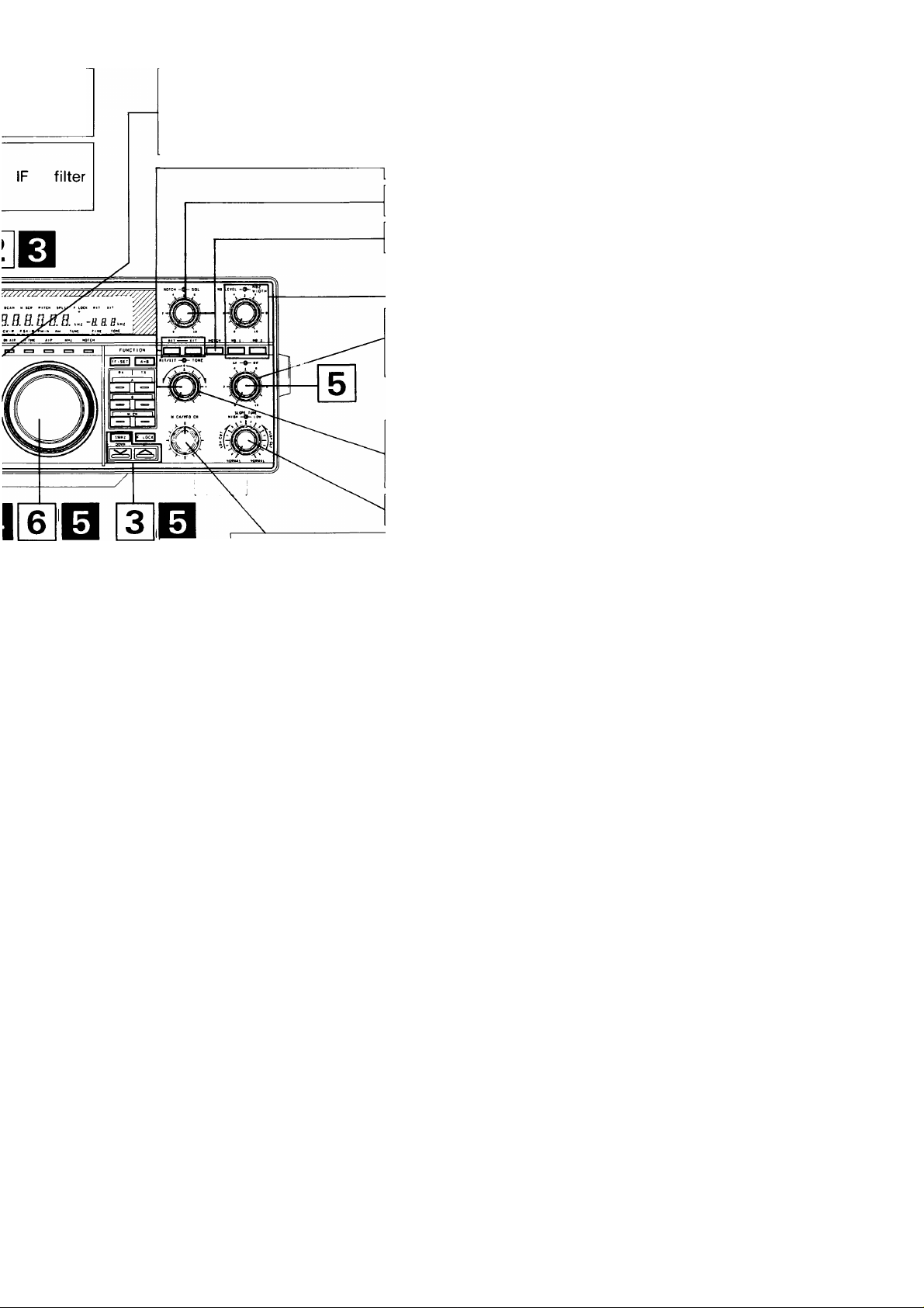
the desired
transmit.
MODE key
Press the LSB/USB key to
alternate between LSB and
USB.
RIT/XIT switch/control
SQL(Squelch) control
FINE key
Makes one turn of the tuning
knob equal 1 kHz (1 Hz
step) to facilitate tuning.
TUNE key
Reduces output power for
linear amplifier adjustment.
NOTCH switch/control
RF gain control
This control should be all the
way to the right.
TONE control
Turn the control to increase
or decrease the tone.
SLOPE TUNE control
M.CH/VFO CH control
This control is also used to
select the desired memory
channel during Memory
Channel Operation.
This control is used to
change the frequency in 10
kHz steps during VFO
operations.
NB switch/control
NB 1 : For pulse type noise,
such as generated by au
tomotive ignition systems.
NB 2 : Noise blanker 2 is used
for long duration pulse
noise, like the “wood
pecker”.
(TRANSMISSION)
D Connect a microphone to the MIC jack.
Q Turn on the DC power supply and then turn the transceiver’s power switch ON.
Q A frequency is shown in the display.
Qj Select USB or LSB with the MODE key.
The automatic switchover point on the transceiver is 9.5 MHz.
Q Enter the desired frequency.
Before transmitting check the frequency for activity so that you do not interrupt another QSO.
Q Press the METER key until the ALC meter lights.
Q Press the microphone PTT switch, or set the REC/SEND switch to SEND.
Q Speak into the microphone and adjust the MIC gain control so that the meter deflection does not exceed the ALC
zone on voice peaks.
Note
Speak into the microphone, holding the microphone
about 5 cm away from your mouth. Close talking or
talking too loudly may reduce transmission clarity or
spread the side bands too much.
—I I I I I
------------
1 3 S T 9 20 40 «006
QOODDQGDDOaOQQDQOOQDOOOOOOOOOO
0 II £1 II Ul 111 V
■ t 1 1 I 1
$WR ooooooaoaooooooQoooooooooooooo
1.1 210
)f- ALC zone -?|
1—T
------
r
Page 22

4-3-1. SSB AUTO mode shift
This transceiver automatically selects the appropriate sideband when in the SSB mode.
30kHz 9.5MHz 30MHz
LSB
Notes
1. USB is selected for 9.5 MHz and above.
2. The AUTO mode selection will not function when using RIT.
USB
4-3-2. Speech Processor
The Speech Processor is used when signals from your station are weak at the distant station.
During SSB operation (especially DX operations), it may be desirable to increase the relative “talk-power” of the
transmitter by using the speech processor circuitry. This may make the difference between a marginal, and a
copyable signal.
•Operation
Turn the PROC switch ON and place the METER switch to COMP. Adjust the PROC control while speaking
into the microphone in a normal tone of voice, for a peak COMP scale reading of no more than 10 dB. Do not
overdrive the COMPRESSOR. This will deteriorate voice quality, increase transmitter noise level, and in
general make copying your signal more difficult.
Next, set the METER switch to ALC and adjust the MIC gain control while speaking into the microphone.
Ensure that the meter deflection is within the ALC zone!
Page 23
4-4. CW OPERATION
AlP switch
When switched on, it
reduces interference from
strong signals.
FULL/SEMI switch
During CW operation, selects
either Full Break-in (FULL) or
Semi Break-in (SEMI).
VOX/MAN switch
Used to select Break-in
operation.
THRU/AUTO switch
THRU; Antenna tuner is off.
AUTO: Antenna tuner is on.
AGC switch
Set to MID
normally.
PLAY, REC keys
Records and plays CW
messages for transmission.
KEY SPEED control
This control the speed of the
electronic keyer.
PITCH key
Select the CW receive tone
(RECEIVING)
pT| Turn on the DC power supply and then turn the transceiver’s power switch ON.
|~2] A frequency is shown in the display.
Press the UP/DOWN switches to select the desired frequency band.
When the 1 MHz step position is selected, the MHz indicator will light.
[4] Select CW with the MODE key.
[~^ Turn the AF gain control clockwise until a signal or noise is heard.
Rotate the TUNING knob and select an open channel.
(Tl
i
i
E
E
E
E
22
E
E
E
Page 24
ER key
to select the desired
r function in transmit.
ER key
ges the
tivity.
MODE key
Press the CW / FSK key to
alternate between CW and
FSK.
NB switch/control
NB 1 : For pulse type noise,
such as generated by au
tomotive ignition systems.
Noise blanker 2 is used
for long duration pulse
noise, like the “wood
pecker”.
ELECTRONIC KEY switch
Turns the electronic keyer on or
off. Turn the switch off when
CW is initiated by a straight key
or when using an external elec
tronic keyer.
M.CH/VFO CH control
iEV key
Reverses the BFO frequency
rom USB to LSB.
This control is used to
change the frequency in 10
kHz steps during VFO
operations.
HNE key
4akes one turn of the tuning
nob equal 1 kHz (1 Hz
tep) to facilitate tuning.
This control is also used to
select the desired memory
channel during Memory
Channel Operation.
^ANSMISSION)
I Connect a key or electronic keyer to the rear panel CW KEY jack.
I Turn on the DC power supply and then turn the transceiver’s power
switch ON. Place the VOX/MAN switch to the VOX position.
I A frequency is shown in the display.
I Select CW with the MODE key.
I Enter the desired frequency.
Before transmitting check the frequency for activity so that you do
not interrupt another QSO.
I Press the METER key until the ALC meter lights.
To use external straight key.
■
Ground Not used
+ 5 V. Contact
Current about 1 mA
+ 5 V, Contact
Current about 1 mA
I Press the key; the ON AIR indicator lights and the meter pointer
deflects.
I Adjust the CAR control until the meter deflection is within the ALC
zone.
OOODQaDQOOQOQaoaaOOQQDODaaODDD
SWR OOOOOOOOOQOO
ALC zone
I Release the key. Receive will be restored and the ON AIR indicator
will turn off.
Electronic keyer connection.
lil
D D
DASH DOT
( )
IIO
Ground
+ 5V
Contact Current
about 1 mA
Page 25
4-4-1. CW zero-beat Operation
In CW operation equalizing the receiving frequency
with that of your transmit is called “Zero beating”.
The TS-850 enable you to zero beat in the following
manner.
You can forceable change the ratio to you own
personal preference or you can select AUTO
WEIGHT control where the weighting adjusts for
changes in keyer speed.
• Auto Weight (Initial state) [When the Power on
function selection (Number 21) is ON.]
Press the TUNE key and adjust the tuning knob so
that the signal from the other transceiver is zero
beat, and deactivate the TUNE key. The CW can
then be used with the other transceiver zeroed in.
B.
1. If the VOX/MAN switch is VOX, set it to MAN and
depress the key.
2. A side tone will be heard from the speaker.
3. Adjust the TUNING knob so that the transmit
frequency of the station you are receiving is equal
to the side tone frequency.
Zero beating is now completed.
4-4-2. PITCH function
You can specify the desired pitch of the receive tone
during CW reception.
1. Press the PITCH key during CW receiving.
2. Select the desired pitch with the M.CH/VFO CH
control.
400-450 - 500-550-600-650 - 700
The dot-dash ratio can be set according to the
keying speed. The reverse mode can be turned on
or off with the power on function (menu number 22).
(Please refer to Section 4-10-15.)
Reverse mode
OFF
The faster the keying
speed the longer the
dash.
KEY SPEED —CAR
The faster the keying
speed the shorter the
dash.
ON
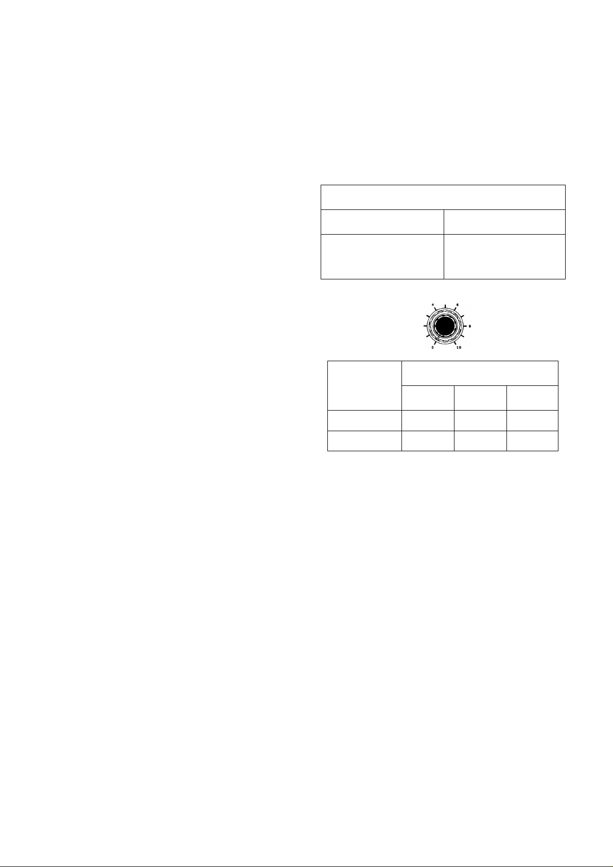
KEY SPEED Control Position
Number 22
OFF
ON
0~3 3~7
1 :2.8
1 :3.2
1 :3.0 1 :3.2
1 :3.0
7~10
1 :2.8
1000--950-- 900--850--800^750
(Initial
state)
(Hz)
3. When the PITCH key is pressed again, the pitch
is set, and the normal frequency display returns.
4. The sidetone frequency is the same as the
frequency set for the pitch.
4-4-3. Electronic Keyer Circuit Operation
Place the ELECTRONIC KEY switch on the rear
panel to ON. Connect a paddle type key to the CW
KEY jack use a 6.0 mm diameter stereo plug.
Adjust the KEY SPEED control for the desired
speed.
■Weight Adjustment
The ratio of dot / space / dash can be adjusted as
follows:
DOT SPACE
1 1
The dot-dash ratio has been factory preset to 1 : 3
and will remain so regardless of the keyer speed.
DASH
3
SPACE
1
Notes
1. It requires a little time to change the ratio at
about the 3 and 7 positions of the KEY SPEED
control where some hysteresis occurs.
2. These dot/dash ratios are only approximate.
• Manual Weight [When the Power on function
selection (Number 21) is OFF.]
The dot-dash ratio can be set between 1:2.5 and
1:4.0 with the power on function (menu number 23).
(Please refer to Section 4-10-15.)
For the CW message storing, see Section 4-13.
DRS function.
■SEMI and FULL break-in operation
Two break-in methods are provided with the
transceiver, SEMI and FULL break-in. With either
break-in operation, depressing the CW key will
cause the radio to transmit without the need for
manually switching the REC / SEND switch. The
difference between FULL and SEMI break-in is that
during FULL break-in operation it is possible to listen
between dots and dashes, and that during SEMI
break-in it is not.
23
Page 26

Note
With either SEMI or FULL break-in operation, cross
band / cross mode operation is not possible.
Additionally, when you are using FULL break-in
you should not work cross band splits, only in the
same band.
This transceiver also provides a sidetone oscillator
circuit to allow monitoring of your CW signal during
transmission.
(a) Semi-automatic break-in
Depressing the CW key will automatically place
the transceiver into the transmit mode. Transmit
mode will be maintained for a period determined
by the setting of the DELAY control on the front
panel of the transceiver, even after the CW key is
released.
(b) Full-automatic break-in
Depressing the CW key will automatically place
the transceiver into the transmit mode. Releasing
the CW key will return the radio to receive
immediately enabling reception between
characters.
■ When the electronic keyer is used as Bug key
When the electronic keyer is used as the Bug key,
turn the function on with the function setting (menu
number 24) at power on. (Please refer to Section 4-
10-15.)
____________________________________
Note
When the ELECTRONIC KEY changeover switch
is on, menu number 24 is displayed.
Cautions
1. The TL-922 / 922A linear amplifier is not
designed for full break-in type operation.
Attempting to use this accessory in the FULL
break-in mode may cause damage to the
linear amplifier.
2. The switching time between transmit and
receive decreases as you increase your
keying speed. This limits the maximum
keying speed that is available during FULL
break-in operation. When using high speed
CW you should use SEMI break-in.
3. During SPLIT operations with FULL break-in,
clicks may be heard in the monitoring tone or
received signal depending on the
combination of the transmit / receive
frequencies.
4. During full break-in, the received audio that
passes through the 250 Hz band CW narrow
filter may click because of its delay time.
5. If the TS-850S is used with CW filter YK88CN-1 (option) or YG-455CN-1 (option), it is
not suitable for full break-in operation
because it has a delay time when the signal
passes through the narrow-band filter. In this
case, you are recommended to perform
SEMI break-in operations.
24
Page 27

(RECEIVING)
rn Turn on the DC power supply and then turn the transceiver’s power switch ON.
0 A frequency is shown in the display.
Press the UP/DOWN switches to select the desired frequency within the 28 MHz amateur radio band.
When the 1 MHz step position is selected, the MHz indicator will light.
0 Select FM with the MODE key.
Turn the AF gain control clockwise until a signal or noise is heard.
^ To eliminate the no signal noise turn the SQL control clockwise to the point the background noise just disappears.
This point is known as the squelch threshold point.
[T] Rotate the TUNING knob and select an open channel.
Page 28

ey to the
If it is set
maximum
ion for
5 kHz.
METER key
Used to select the desired
meter function in transmit.
MODE key
Press the FM / AM key to
alternate between FM and
AM.
_
SQL(Squelch) control
RF gain control
This control should be all the
way to the right.
TONE control
Turn the control to increase
or decrease the tone.
M.CH/VFO CH control
This control is used to
change the frequency in 10
kHz steps during VFO
operations.
This control is also used to
select the desired memory
channel during Memory
Channel Operation.
(TRANSMISSION)
Q Connect a microphone to the MIC jack.
Q Turn on the DC power supply and then turn the transceiver’s power switch ON.
Q A frequency is shown in the display.
Q Select FM with the MODE key.
Q Enter the desired frequency within the 28 MHz amateur radio band.
Before transmitting check the frequency for activity so that you do not interrupt another QSO.
Q Press the METER key until the ALC meter lights.
B Press the microphone PTT switch, or set the REC/SEND switch to SEND.
B Speak into the microphone and adjust the CAR control so that the meter deflection does not exceed the ALC zone on
voice peaks.
Note
Speak into the microphone, holding the microphone
about 5 cm away from your mouth. Close talking or
talking too loudly may reduce transmission clarity or
spread the side bands too much.
1 3 S 7 9 20 40 900B
ODOODDOQOODOOOODOOGOOOOQQaODQD
PWR t_
--------
ALC ——
SWR oaaaooaoooaaoQooooooooo
COMP 1 t.l 210 3 20
|<— ALC zone-^
II M II Ml 111 V
25
Page 29

4-6. AM OPERATION
ATT switch
This switch allows attenuation of
the input signal by 6, 12 or 18 dB.
METER key
H Used to select t
meter function in t
AlP switch
When switched on
reduces interference
it
from
strong signals.
VOX/MAN switch
Used to operate VOX.
THRU/AUTO switch
THRU: Antenna tuner is off.
AUTO: Antenna tuner is on.
AGO switch
Becomes the time constant
for AM only regardless of the
position. (Except OFF)
HIGH BOOST switch
The high-frequencies of the
transmitted sound are emphasized.
MIC gain control
Microphone gain can be
adjusted during operation.
1
□□ ^ <=i
ïi‘0
FILTER key
Changes the
selectivity.
7/^ 'V/ ////////////////,
V/////////A 77)
CiTDCuD r% i
ESCE a a H *
LajOij tt a ÏÎ. jrm)r*i
CAR contre
Used to a(
during AM.
PWR control
Power can be controlled in
all modes.
(RECEIVING)
n~l Turn on the DC power supply and then turn the transceiver’s power switch ON.
Q A frequency is shown in the display.
Press the UP/DOWN switches to select the desired frequency band.
When the 1 MHz step position is selected, the MHz indicator will light.
Q Select AM with the MODE key.
Turn the AF gain control clockwise until a signal or noise is heard.
6 Rotate the TUNING knob and select an open channel.
26
Page 30

he desired
ransmit.
MODE key
Press the FM / AM key to
alternate between AM and
FM.
RIT/XIT switch/control
SQL(Squelch) control
RF gain control
This control should be all the
way to the right.
TONE control
Turn the control to increase
or decrease the tone.
SLOPE TUNE control
NB switch/control
NB 1 : For pulse type noise,
such as generated by au
tomotive ignition systems.
NB 2 : Noise blanker 2 is used
for long duration pulse
noise, like the “wood
pecker”.
M.CH/VFO CH control
II
jjust carrier level
This control is used to
change the frequency in 10
kHz steps during VFO
operations.
This control is also used to
select the desired memory
channel during Memory
Channel Operation.
(TRANSMISSION)
D Connect a microphone to the MIC jack.
Q Turn on the DC power supply and then turn the transceiver’s power switch ON.
Q A frequency is shown in the display.
Q Select AM with the MODE key.
Qj Enter the desired frequency.
Before transmitting check the frequency for activity so that you do not interrupt another QSO.
Q Press the microphone PTT switch, or set the REC/SEND switch to
SEND.
Adjust the CAR control so that the meter indicates as shown Fig.1.
Speak into the microphone and adjust the MIC gain control so that
the meter indicates as shown Fig.2.
Note
If the MIC gain control is advanced too far for clockwise, the
transmit signal will become distorted.
__________________________
40 W
T-1-1-1-1 -1--1--r
1 3 S 7 9 20 40 600B
IHIIIIIIHIIIQOOOOOOGOQOOOOQO
PWR I I I I
SVR
SvR oooaaaoooQoooooooooooooo
COMP
80 W
PWR 1
SWR oooooooooooooooooooooo
--------- ALC
-Í - I > 1
-------------
Fig. 2
Page 31

4-7. FSK OPERATION
AlP switch
When switched on
reduces interference from
strong signals.
THRU/AUTO switch
THRU: Antenna tuner is off.
AUTO: Antenna tuner is on.
AGC switch
Normally set to FAST.
ATT switch
This switch allows
attenuation of the input
signal by 6, 12 or 18 dB.
it
METER key
Used to select the desirec
meter function in transmit.
FILTER key
Changes the
PWR control
Power can be controlled in
all modes.
TUNE key
Used when adjusting a linear
amplifier.
(RECEIVING)
rn Connect the RTTY keyboard to the RTTY terminal on the rear panel.
I 2 I Turn on the DC power supply and then turn the transceiver’s power switch ON.
A frequency is shown in the display.
RH Press the UP/DOWN switches to select the desired frequency band.
When the 1 MHz step position is selected, the MHz indicator will light.
Select FSK with the MODE key.
Turn the AF gain control clockwise until a signal or noise is heard.
\
REV key
Reverses the BFO frequ
from LSB to USB.
FINE key
Makes one turn of the ti
knob equal 1 kHz ('
step) to facilitate tuning.
|T] Rotate the TUNING knob and select an open channel.
Page 32

MODE key
Press the CW / FSK key to
alternate between CW and
FSK.
RIT/XIT switch/control
NOTCH switch/control
RF gain control
This control should be all the
way to the right.
TONE control
Turn the control to increase
or decrease the tone.
SLOPE TUNE control
NB switch/control
NB1 : For pulse type noise,
such as generated by
automotive ignition
systems.
NB2 : Noise blanker 2 is
used for long duration
pulse noise, like the
“woodpecker”.
RTTY terminal
For connection to an RTTY inter
face unit. A shorting pin is insert
ed into the RTTY terminal at the
factory. With the shorting pin in
serted, the mark signal with the
display frequency is transmitted.
If the shorting pin is removed,
the space signal is transmitted.
1
0
'®o o o
0
RTTY DSP 1 OSP 2
M.CH/VFO CH control
This control is used to
ency
change the frequency in 10
kHz steps during VFO
operations.
This control is also used to
jning
I Hz
select the desired memory
channel during Memory
Channel Operation.
ACC2 connector
Connect to the FSK terminal.
(TRANSMISSION)
D Connect the RTTY keyboard to the RTTY terminal on the rear panel.
B Turn on the DC power supply and then turn the transceiver’s power
switch ON.
B A frequency is shown in the display.
D Select FSK with the MODE key.
B Enter the desired frequency.
Before transmitting check the frequency for activity so that you do
not interrupt another QSO.
B Press the METER key until the ALC meter lights.
©
S © © © M ®
ANTI GAIN 0£LAY key
'
------
VOX
-------
ACC 2 connections.
»
B Set the REC/SEND switch to SEND. Or key the transceiver from the
FSK terminal.
B Adjust the CAR control so that the meter deflection is within the ALC
zone.
s —I—I—1
OOOaaQOQODODQOQOOODDOOOQDDQQQD
SVR ooooooooocaaoaaaoooaooooooooooa
I^ALC zone-^
-------
1—1
---------
1---------------1---------------r
B Operate the RTTY keyboard.
B the REC/SEND switch to REC or unkey the transceiver from the
FSK terminal to return to the receive mode.
The FSK shift width is set to 170 Hz. It can
be changed to 200,425 or 850 Hz. (Please
refer to Section 4-10-15.)
The FSK receive tone is set to 2125 Hz
(high). It can be changed to 1275 Hz (low).
(Please refer to Section 4-10-15.)
27
Page 33

4-8. PACKET(AFSK) OPERATION
AlP switch
When switched on
reduces interference
strong signals.
THRU/AUTO switch
THRU: Antenna tuner is off.
AUTO: Antenna tuner is on.
AGO switch
Normally set to FAST.
from
METER key
Used to select the d(
meter function in transn
it
PWR control
Power can be controlled in
all modes.
(RECEIVING)
[~n Connect the communication terminal signal line to the ACC2 connector on the rear.
[2] Turn on the DC power supply and then turn the transceiver’s power switch ON.
A frequency is shown in the display.
Q Press the UP/DOWN switches to select the desired frequency band.
When the 1 MHz step position is selected, the MHz indicator will light.
Select LSB or USB with the MODE key.
16 I Turn the AF gain control clockwise until a signal or noise is heard.
p7] Rotate the TUNING knob and select an open channel.
FINE key
Makes one turn of t
knob equal 1 kH
step) to facilitate tur
Since AFSK using the SSB mode is normally used for 300 baud packet transmissions, the AFSK signal is applied to
the MIC signal line. This is possible in both the USB and LSB modes, but the frequency of the signal that is actually
transmitted is the display frequency plus the modulation frequency in USB mode, and the display frequency minus
the modulation frequency in LSB mode. Since various modulation frequencies are used by different TNC’s, you
should determine the correct operating frequency, taking the AFSK frequency of the TNC that you are using into
consideration when performing your calculations.
28
Page 34

MODE key
Press the LSB/USB key to
alternate between LSB and
USB.
RIT/XIT switch/control
SQL(Squelch) control
NOTCH switch/control
RF gain control
This control should be all the
way to the right.
TONE control
Turn the control to increase
or decrease the tone.
SLOPE TUNE control
NB switch/control
NB1 : For pulse type noise,
such as generated by
automotive ignition
systems.
NB2 : Noise blanker 2 is
used for long duration
pulse noise, like the
“woodpecker”.
93385;—
^
___
<an~te
0^
© ©
©o o o
©
he tuning
z (1 Hz
ling.
M.CH/VFO CH control
This control is used to
change the frequency in 10
kHz steps during VFO
operations.
This control is also used to
select the desired memory
channel during Memory
Channel Operation.
LINEAR AMP switch
Activates the relay for the
linear amplifier control. If the
linear amplifier relay operates
slowly, you may need to
make a retry. Check the
TNC parameter setting.
(TRANSMISSION)
Q Connect the communication terminal signal line to the ACC 2
connector on the rear.
Q Turn on the DC power supply and then turn the transceiver’s power
switch ON.
Q A frequency is shown in the display.
D Select LSB or USB with the MODE key.
Q Enter the desired frequency.
Before transmitting check the frequency for activity so that you do
not interrupt another QSO.
1
ACC 2 connector
Connect the data communica
tions devices.
Connect the ACC 2 connector.
■- Standby
Moduration
output
GND
■4
AF INPUT
Q Press the METER key until the ALC meter lights.
B Enter a transmit command from the communication terminal (generally, from the keyboard), and adjust the MIC gain
control so that the meter deflection is within the ALC zone.
Notes
1. Follow the instructions contained in your terminal units operating manual for the correct settings before you start transmitting.
2. If the output of the terminal unit causes the ALC meter to register above the recommended limits even with the MIC
gain control turned all the way down you should reduce the output of the terminal unit. Excessive signal levels can
cause distortion! If the terminal unit output level is fixed you should add a potentiometer between the transceiver and
the terminal unit. (Refer to Section 6-4-4.)
Page 35

4-8-1. RTTY
RTTY operation requires a demodulator and a
teletypewriter. A demodulator including 2125 and
2295 Hz (170 Hz shift) filters, will be acceptable and
may be connected directly to the REMOTE
connector. To use the transceiver’s FSK circuit with
older high voltage teletype equipment, you must use
an external keying relay in the teletypewriter closed
loop, and connect the relay contacts to the rear
panel RTTY terminal.
During FSK operation, the MARK frequency is
shown on the display.
RTTY SYSTEM
This transceiver will adapt to Slow Scan Television
or AFSK (Audio Frequency Shift Keying) RTTY
operation.
For SSTV, the ACC 2 connector should be
connected to the Camera output. The ACC 2
connector should be connected to the monitor input.
For AFSK operation, connect the Tone Unit output to
the ACC 2 input, and ACC 2 output to the Tone Unit
input.
RTTY jack TS-850S
AFSK keying signal.
RTTY devic<
AFSK receive signal
SS (Standby)
The figure below shows the frequency relationship
between receive and transmit with this transceiver.
In FSK operation the mark frequency is indicated on
the display.
Speaker terminal
Normally a mark frequency is transmitted when
the key is closed, and the space frequency is
transmitted when the key is open. Since a
shorting pin is inserted into the RTTY terminal at
the factory, the mark frequency is transmitted.
The polarity can be reversed so that the mark
frequency is transmitted when the key is open
with a power on function. (Please refer to Section
4-10-15.)
4-8-2. DATA COMMUNICATIONS
(PACKET, AMTOR, RTTY, SSTV,
etc.)
1. The ACC 2 connector has been provided for
connection of Data communications devices. All
necessary connections can be accomplished from
the same connector.
2. When using AFSK (Audio Frequency Shift Keying)
or modulating the signal with any form of audio
tones you should select LSB or USB. If F2
operation is desired select the FM mode. In
general LSB is used for RTTY and PACKET
communications in the HF band (FI), and USB is
used for AMTOR.
3. The transceiver will transmit according to the
signals received on the STBY connector. These
inputs are generated by the terminal unit in
response to inputs from the associated terminal
input device.
4. When using LSB, or USB the MIC gain control
should be used to adjust the input level for an on
scale ALC meter reading.
5. Pin number 9 of the ACC 2 connector is used to
disable the front panel microphone connector
during the periods that your communication
terminal is in use (grounding the pin accomplishes
this task). This prevents unwanted errors from in
your text.
Note
The display frequency 14.200.00 MHz.
The BFO normally uses the LSB mode for RTTY
operation. When the REV key is pressed, the
BFO changes to the USB mode. In the FSK-R
(FSK reverse) state, the display frequency is the
space frequency. If the other transceiver is using
reverse shift, the receiver polarity can be adjusted
with the REV key.
The display indicates the mark frequency even if
the shift width is changed.
29
Page 36

4-9. AUTO ANTENNA TUNER
OPERATION
If the transceiver is operated into an antenna with a
high SWR, the final stage SWR protection circuit
may operate (when SWR is greater than
approximately 2 : 1). Use of the Automatic Antenna
Tuner will help you to match the antenna to the
transceiver. The AT unit is capable of matching a 20
- 150 ohm load, or approximately a 2.5 : 1 SWR. If
the antenna and feed line exceed this range the
tuner may not be able to find the correct match. If
the tuner cannot match after two attempts, check
your antenna and feed lines.
Output power of the transceiver will automatically be
reduced to approximately 10 watts during the tuning
process to protect the finals against damage.
______
Note
The carrier control should be adjusted for normal
CW output (at least 10 watts).
While the automatic antenna tuner is capable of
reducing the apparent SWR of the antenna system,
it is important to remember that maximum power
output will only occur when the antenna has been
adjusted for the lowest possible SWR.
2. Set the AT TUNE switch to ON.
The transceiver switches to the CW mode, the AT
TUNE indicator lights, and the unit starts tuning.
Note
This switch will not function when the CAR
control is turned fully counterclockwise.
3. When tuning is completed and the AT TUNE
indicator goes out, the frequency display returns
automatically.
4. A warning beep tone is sounded if tuning is not
completed within 20 seconds. If this occurs turn
the AT TUNE switch OFF, and then repeat steps
1 - 3.
@ Manual Tune mode
Manual adjustment of the tuner is possible with the
tuning knob and M.CH/VFO CH control if auto-tuning
is not possible.
1. Press and hold the LSB/USB key while you turn
on the POWER switch.
2. Select the number 20 by rotating the M.CH/VFO
CH control.
Use the UP/DOWN switch to select OFF.
The antenna tuner has the following three modes;
® Preset mode
This transceiver has a Preset Memory function
capable of storing tuning conditions of each amateur
radio band. The transceiver stores the tuning
conditions after tuning of an amateur radio band is
completed, and automatically provides the stored
tuning conditions when switched backed to that
amateur radio band from other amateur radio bands,
reducing the time for tuning. When you switch to an
amateur radio band, the AT TUNE indicator lights
briefly to indicate that the Preset function is
operating.
1. Set the THRU/AUTO switch to AUTO.
The AT TUNE indicator will light and the
transceiver will adjust to it’s preset condition.
2. When preset is completed, the AT TUNE indicator
turns off.
Note
If you change BANDS and then return to the
previously tuned BAND, after tuning is complete,
the SWR may have changed.
If the SWR has changed, set the AT TUNE switch
to ON so the unit will retune.
(2) Auto Tune mode
r r
1
c' LI
o r
3. Press the CLR key, or press the POWER switch
OFF and then back ON.
4. Place the THRU/AUTO switch to AUTO.
5. Turn the AT TUNE switch ON. While reading the
SWR meter, alternately turn and adjust the
TUNING knob and M.CH/VFO CH control for the
lowest SWR. When tuning is completed, the AT
TUNE indicator will go out. Once it goes out,
further tuning will not be possible even if you turn
the controls.
6. The current setting is stored in memory as the
preset data for the amateur band when the AT
TUNE indicator turns off or you stop tuning by
pressing the AT TUNE switch.
If manual tuning is done in one band, then again
in another only, the tuning data for the first band
is memorized. So, if the first band is reselected,
the memorized tuning data is recalled,
reestablishing the original tuning.
7. To cancel the manual tuning mode, perform step
1, select ON in step 2, and then step 3.
_________
Note
If manual adjustment fails to lower the SWR and
complete the tuning, adjust the SWR of the
antenna.
In this mode, tuning signals are transmitted to tune
the antenna and transceiver automatically.
Note
If switch SW 1 on the rear is set to EXT, the built-
in antenna tuner does not work.
1. Set the THRU/AUTO switch to AUTO.
30
Page 37

4-10. OTHER OPERATION 4-10-1. Beep T ones
The frequency step in the AM and FM modes can
be set to 10 Hz. (Please refer to Section 4-10-15.)
Audible confirmation of various microprocessor
functions is provided in the form of a series of audio
beeps. The output level of the “Beeper” is
adjustable with a variable resistor located inside the
set. (Please refer to Section 6-6-3.)
4-10-2. Audible Mode Announcement
When a Mode key is pressed, the first character of
the mode is sounded in Morse code thru the
speaker. (Note that FSK is announced with an “R”)
Mode
LSB
USB
CW
FSK
AM
FM
Morse Code
• — • •
• • i—
—^ • _ •
• — •
•
• • — •
4-10-3. Alarm Function
Several alarms have been included to signal errors
that you might encounter. The chart below lists the
possible causes and the resulting Morse code alarm.
Morse code will be heard from the speaker.
Indication
Morse Code
B. M.CH/VFO CH control
1. The active VFO frequency step is as shown
below.
Frequency Step
10 kHz
The frequency step may be reprogrammed when
turning on the POWER switch. (Please refer to
Section 4-10-15.)
2. This control is also used to select the desired
memory channel during Memory Channel
Operation.
One revolution of
M.CH/VFO CH control
240 kHz
4-10-5. Amateur Radio Bands selection
Press the UP/DOWN switch to change amateur radio
bands.
4-10-6. Direct keyboard frequency entry
Direct keyboard entry of the operating frequency is
possible using the Numeric Keypad on the
transceiver. This allows rapid changes in frequency
without the delays encountered when using other
tuning methods.
Note
You cannot enter any frequency which is outside
the coverage of the radio.
_____________________________
• When the SCAN key is pressed
and the receiver is unable to
execute memory scan.
• When all memory channels are full
and attempt is made to find an
empty channel with the 1 MHz
switch ON.
• When all memory channels are
empty and an attempt is made to
select memory channel with the 1
MHz switch ON.
When you exceed the operating
limits while using the numeric keys
to enter a frequency.
CHECK
OVER
4-10-4. Frequency Step
A. TUNING knob
The frequency step depends on the mode that has
been selected.
Mode
SSB/CW/FSK
AM/FM 100 Hz 50 kHz
When the FINE function is ON, the frequency step is
1 Hz.
Frequency
Step
10 Hz 10 kHz
One revolution
of TUNING knob
1. Press the ENT key. The display will indicate.
ENT
I
2. Enter the desired operating frequency from Most
Significant Digit to the Least Significant Digit. You
do not have to enter trailing zeros, but you must
enter leading zeros.
1
0
When 3 is entered into the 10 MHz digit and then a
number is entered into the 100 kHz digit, the band is
shifted to the 3 MHz band.
U
I
I.
n
J
J.
31
Page 38

D C
J U
n
is possible to work cross band, cross mode if
desired.
3. After the least significant digit has been entered
press the ENT key again to signify you want the
radio to change frequency. If you entered the
frequency down to the nearest 10 Hz a beep will
sound and the radio will automatically change to
the new frequency without the need of pressing
the ENT key for the second time.
For example;
To enter 14.200.00 MHz there are two methods:
Method one; Press [ENT], [l], [4], [2], [ENT]
Method two: [ENT], [l], [4], [2], [0], [0], [0], [0]
□D E d]
4. If you make a mistake while entering the
frequency and have not yet pressed the ENT key,
or entered the final digit, you may cancel the input
by pressing the CLR key or the PTT switch.
ENT
f
I, L U U, U U
I I n n n n
4-10-7. Dual Digital VFO’s
Operational convenience is enhanced thru the use of
two VFO’s.
Two VFO’s are provided to allow you to change
frequencies rapidly with the least amount of dial
rotation. For example; you could set one VFO to the
lower tuning limit and the other VFO to the upper
tuning limit.
A = B key
Depressing this key causes the data contained in
the inactive VFO (the VFO that is not currently
being displayed in the display area) to change to
the same data that is contained in the active VFO
(the one currently displayed). Both the frequency,
mode and filter selection are changed.
Note
When a memory channel is being used
reception, the A = B key will not function.
For example:
RX VFO A is set at 7 MHz in LSB, and RX VFO B
is 14 MHz in USB. RX VFO A is the active VFO
(shown on the display). Depressing the A = B key
will cause RX VFO B to change to 7 MHz in LSB.
for
To avoid confusion during contest, or pile-up
operations we recommend using VFO A for receive
and VFO B for transmit.
•TF-SET key
Depressing this key will allow you to rapidly set or
check the transmit frequency, during SPLIT
operations, without the need of actually transmitting.
This key is especially convenient when you are
trying to locate the transmit frequency of the station
currently in contact with the DX station, since
depressing this key allows you to receive on the
transmit frequency as long as the key is held
depressed. The TUNING knob is active when this
key is depressed, so it is easy to change your
transmitter frequency at the same time, if necessary.
Releasing the key will return you to the original
receive frequency.
4-10-9. Interference Reduction
■All mode
[ I ] SLOPE TUNE control (Except FM mode)
During reception, these controls permit you to
reduce the apparent IF filter bandwidth and therefore
reduce adjacent channel interference.
•SLOPE TUNE HIGH CUT control
Adjust the HIGH CUT control counterclockwise,
and interference from signals higher than the
operating frequency will be reduced. The high-
frequency components of the resulting receiver
audio will also be reduced.
•SLOPE TUNE LOW CUT control
Adjust the LOW CUT control clockwise, and
interference from signals lower than the operating
frequency will be reduced. As with the HIGH CUT
control, use of the LOW CUT control will also
affect the audio frequency passband. In this case
the low frequency components of the audio signal
will be reduced.
Maximum bandwidth occurs with the LOW CUT
control fully counterclockwise, and the HIGH CUT
control full clockwise.
4-10-8. SPLIT FREQUENCY OPERATION
Different frequencies can be set for VFO A, VFO B
and for memory.
For example:
VFO A is the active VFO, and VFO B is the inactive
VFO. Depressing the TX VFO B key will cause the
transceiver to receive on VFO A and transmit on
VFO B. The mode of reception and transmission will
follow the mode contained in the appropriate VFO. It
32
Page 39

Notes
1. In the FM mode, only 12 kHz (wide) and 6
kHz (narrow) can be selected.
2. Some bandwidths cannot be selected unless
the required filter is installed.
3. Either optional YG-455C-1 or YG-455CN-1
can be installed. When the YG-455CN-1 is
installed, 500 is displayed.
4. When an optional filter is installed, change
the filter switch. (Please refer to Section 7-1.)
Initial state
MODE
FILTER
8.83MHz
455kHz
[ II ] Filter key
The filter bandwidth for the 8.83 MHz and 455
kHz ifs can be selected from the front panel. Up
to 3 additional filter bandwidths may be added
thru the installation of optional filters.
8.83MHz filter bandwidth
The value changes each time the 8.83 switch
is pressed.
-►6k
No indicator
(LC Filter)
Notes
1. This function is not active in the FM mode.
2. Some bandwidths cannot be selected unless
the required filter is installed.
3. When an optional filter is installed, change
the filter switch. (Please refer to Section 7-1.)
4. If the YK-88SN-1 is installed, install it where
the YK-88C-1 or YK-88CN-1 is installed. The
number 500 or 270 is displayed.
455kHz filter bandwidth
The value changes each time the 455 switch is
pressed.
------
► 12k
500
-►2.7k
---------
500
-270-^-
► 6k ------------------
2.7k
SSB, CW, FSK 2.7k
AM 6k 6k
FM 12k
Note
When bandwidth of the 8.83 MHz filter is
approximately the same as that of the 455 kHz
filter, the combined bandwidth will be narrower
than the indicated bandwidth.
For example, when both the 8.83 MHz and 455
kHz filters are set to 2.7k, the combined bandwidth
will be about 2.4 kHz.
[Ill] NOTCH control (Except FM mode)
Use this control when you are experiencing
interference from a CW heterodyne type signal. Turn
the NOTCH ON and slowly adjust the NOTCH
control to minimize the beat signal. A beat of
approximately 1.5 kHz can be reduced at the
approximate center position of the control. Please
note that this control will not eliminate SSB, AM or
FM type interference. The bandwidth of such signals
is approximately 3-6 kHz wide. When in the USB,
CW or AM mode a beat tone lower than the center
frequency can be reduced by rotating the control
clockwise from the center point. In LSB or FSK
mode adjust the control counterclockwise.
Notes
1. The NOTCH frequency can be varied within a
range of approximately 400 to 2600 Hz.
2. When an interfering signal such as a CW station
appears, slowly rotate the NOTCH control. If
you rotate the knob too quickly you may pass
right over the notch point. Slow rotation will yield
best results.
3. The NOTCH frequency may be shifted by the
SLOPE TUNE position. Operate the SLOPE
TUNE control, then the NOTCH control.
4. If the NOTCH frequency equals the frequency of
the desired signal (SSB), the desired signal is
attenuated slightly, but this is not in an error.
5. Since the notch is a filter with a very sharp
attenuation characteristic, the adjustment point
may be shifted. (Please refer to Section 6-6-6.)
2.7k
33
Page 40

NOTCH operation (LSB mode)
4-10-10. Noise Blanker
•NB 1 switch
For pulse type noise, such as generated by
automotive ignition systems, turn the NB 1 switch
ON.
When pulsating noise, such as that caused by
automobile ignitions is encountered, place the NB
1 switch ON.
This switch will not help to eliminate atmospheric
or line noises, only pulse type noise.
•NB 2 switch
Noise blanker 2 is used for long duration pulse
noise, like the “woodpecker”. To reduce
“woodpecker” radar noise interference, set switch
NB 2 to the ON position (NB 2’s effectiveness
depends on the specific type of interference). If
you use NB 2 for short duration pulse noise, the
receive tone may become distorted, making it
difficult to hear.
Unfortunately no noise blanker can remove all
different types of interference; but the two noise
blankers that have been provided in the TS-850
are effective in most cases.
If there is no “woodpecker” present, the switch
should be in the OFF position.
•NB LEVEL control
Controls the noise blanker operating level.
Use only the minimum level necessary.
>NB2 WIDTH control
Controls the width of the blanking pulse when NB
2 operates. Adjust the width so that the desired
signal can be received most clearly.
Notes
1. The control only works when there is
woodpecker noise.
2. If this control is turned too far, the received
signal may be interrupted. Set the control to
the best position.
4-10-11. VOX OPERATION
Depress the VOX switch. While speaking into the
microphone, increase the GAIN control until the VOX
relay just operates. Clockwise rotation of this control
will increase the sensitivity. For VOX operation it is
sometimes desirable to “Close-Talk” the microphone
in order to prevent background noises from tripping
the transmitter.
1. Check that the ALC reading on voice peaks is still
within the ALC zone on the meter. If necessary,
readjust the MIC gain control for the proper ALC
reading.
2. If the VOX circuit is activated by the output from
the speaker, adjust the ANTI control as necessary
for proper VOX operation.
3. Do not use excessive VOX or ANTI VOX settings.
This may cause the VOX circuit to operate
erratically. Use only the minimum necessary
control setting.
4. If the VOX circuit transfers between words, or
holds too long, adjust the release time-constant
using the DELAY control.
4-10-12. ON AIR MONITOR
I . MONI switch
Turn the MONI switch ON to monitor the
transmitted signal. Headphones are
recommended.
II. MONI control
Adjust monitor volume level.
Note
This function is not active in the AM and FM mode.
4-10-13. RIT control
The RIT control allows shifting the receiver
frequency ±1.2 kHz. Use of the RIT control will not
affect the transmit frequency.
The RIT step size is either 10 Hz or 20 Hz. (Please
refer to Section 4-10-15.)
When the RIT switch is ON, the RIT indicator will
light, and the receive frequency can be adjusted by
using the RIT/XIT control.
34
Page 41

Note
When the RIT is ON the transmit frequency may
be different from the receive frequency. For normal
operation leave the RIT switch OFF. It should be
used only when necessary.
4-10-14. XIT control
Transmitter Incremental Tuning is very similar to
RIT. XIT is only active in the transmit mode. By
using the XIT function it is possible to offset the
transmit frequency without the normal loss of
receiver audio that is experienced when using the
SPLIT function. The XIT step size is either 10 Hz or
20 Hz. (Please refer to Section 4-10-15.)
Offsets of ±1.2 kHz are possible.
The RIT/XIT offset can be preset, without affecting
the actual operating frequency by turning OFF the
RIT/XIT and using the RIT/XIT display to determine
the offset.
4-10-15. Power on function selection
Several of the functions of this transceiver can be
changed at the time the transceiver is turned ON.
Repeat to release each function.
1. Press and hold the LSB/USB key while you turn
on the POWER switch.
2. A number will appear in the display.
3. Select the desired number by rotating the M.CH/
VFO CH control.
4. Change the function by pressing the UP/DOWN
switch.
5. Function selection can be turned off by pressing the
CLR key, or by pressing the POWER switch OFF and
back ON.
No.
00 Beep tones: ON/OFF
Programmable functions Initial state
ON
No. Programmable functions
UP/DOWN switch step
06
07
08 SSB AUTO mode shift: ON/OFF
09
10
11
12
13
14 Program scan hold: ON/OFF
15
the frequency with the tuning
16
knob (ON) or not (OFF) when
the standard memory channel is
frequency selection:
1000 kHz/500 kHz/1 kHz
(When 1 MHz key is ON.)
10 Hz display resolution:
ON/OFF
Meter peak hold: ON/OFF
Automatically increments the
memory channel data time each
time you enter a frequency into
memory.
FSK transmission key short:
OFF(SPACE)/ON(MARK)
The shift range of the FSK mode
can be set to 170, 200, 425, or
850 Hz by using the UP/DOWN
switch.
You can switch between FSK
mode receive tones high (2125
Hz) and low (1275 Hz).
Storing the band frequency
before the UP/DOWN switch is
pressed : Required(ON)/Not
required(OFF)
Determine whether to change
recalled to RX VFO.
Initial state
1000 kHz
ON
ON
OFF
OFF
OFF
170 Hz
2125 Hz
OFF
ON
OFF
Audible mode announcement:
01
02
03
04
05
ON(Morse code)/OFF(Beep
tones)
Audible alarm:
ON(Morse code)/OFF(Beep
tones)
M.CH/VFO CH control step
frequency selection:
10 kHz/5 kHz/1 kHz
M.CH/VFO CH control step
frequency selection:
10 kHz/9 kHz (AM mode only)
TUNING knob step frequency
selection: 100 Hz/10 Hz (AM
and FM mode only) (Except the
FINE function is ON.)
ON
ON
10 kHz
10 kHz
100 Hz
17
18
19
20
21
22
RIT/XIT variable range:
1.27 kHz/2.54 kHz
Select the sub tones
Sub tones:
b(Tone burst)/c(Continuous
tones)
Antenna Tuner:
ON(AUTO)/OFF(MANUAL)
(When the SW1 switch is INT.)
Auto weight function : ON/OFF
(When the ELECTRONIC KEY
switch is ON.)
Reverse mode: ON/OFF
(When Auto weight function is
ON.)
1.27 kHz
88.5 Hz
c
ON
ON
OFF
35
Page 42

No. Programmable functions
Select the Manual weight
23
24
25
(When Auto weight function is
OFF.)
Bug key: ON(Used)/OFF(Not
used)
(When the ELECTRONIC KEY
switch is ON.)
When split is selected, the
temporary display of the transmit
frequency can be turned on and
off.
Initial state
3.0
OFF
ON
26
27
28
29
30
31
32
33
Display for the 50 MHz
converter: ON/OFF
Display for the 144 MHz
converter: ON/OFF
Display for the 430 MHz
converter: ON/OFF
Change the REC 1 recording
time to 8 or 16 seconds. (When
optional DRU-2 is installed)
Change the REC 2 recording
time to 8 or 16 seconds. (When
optional DRU-2 is installed)
Change the REC 3 recording
time to 16 or 32 seconds.
(When optional DRU-2 is
installed)
Transfer function when two TS-
850 are connected : ON/OFF
Turn on and off direct writing
into VFO by the transfer function
when two TS-850 are
connected.
OFF
OFF
OFF
8 seconds
8 seconds
16
seconds
OFF
OFF
The IF and AF circuits of this
transceiver can be switched off
34
(mute mode) so the transceiver
will not transmit even if the
standby terminal is grounded.
Transfer function when two TS-
35
Notes
1. When menu number 26, 27, or 28 is turned on,
2. Menu number 34 can mute the IF and AF
850 are connected (SPLIT):
ON/OFF
the other two menu numbers are not displayed.
circuits only, not the RF circuit. So if excessive
power is applied to the ANT connector during
muting, the RF circuit may be damaged. Do not
apply excessive power directly to the muted
side of the transceiver.
OFF
OFF
36
Page 43

4-11. MEMORY
4-11-4. Memory Contents
The transceiver incorporates a convenient 100
channel memory that can be used to store and recall
commonly used frequencies.
4-11-1. Microprocessor back-up lithium
battery
A lithium battery is contained in the transceiver to
retain memory. Turning off the POWER switch,
disconnecting the power cable, or a power failure will
not erase the memory. The battery should last for
approximately five years. When the battery
discharges, an erroneous display may appear in the
display. Lithium battery replacement should be
performed by an authorized KENWOOD service
facility; either your KENWOOD servicing dealer
authorized service center, or the factory, since this
unit contains CMOS type circuitry.
Notes
1. When the lithium battery
microprocessor must be
procedure in section 4-11-2.
2. When the lithium battery fails, the radio’s
operating system is not affected. Only
information stored in memory will be cleared.
_____________
is replaced,
reset, using
the
the
Each Memory Channel is capable of storing the
following information: 0=yes, X =no
00~89 90~99
Frequency
Mode
Filter
Tone Frequency data
Tone ON/OFF
Highest/Lowest
operating frequency
AlP ON/OFF
o o
o
o
Q*i)
Q*«i)
X
o
Q*2)
Q*2)
X
X
o
0(M2)
^1 When the memory is used as a split memory in
FM mode for both transmission and reception.
^2 During memory channel operation, the modified
contents are saved as the memory channel
data.
4-11-5. Memory Entry
A. Standard Memory Channel
4-11-2. Initial state and reset of the
microprocessor.
A. Initial state of the microprocessor from the
factory.
Frequency
VFO A 14.000.00
VFOB 14.000.00
Mode
USB
USB
Memory Channel
00~99
B. Microprocessor reset
There are two
methods
for resetting the
microprocessor.
1. Press and hold the A = B key and turn on the
POWER._________________________________
Caution
All user programmed memory will be erased
with this operation.
2. Press and hold the RX-A key and turn on the
power to reset all user programmed data except
the contents of the Memory Channels.
4-11-3. Memory Channel
Memory Channel
Number
Memory Channel
1. Select the receive frequency, the mode and the
filter.
Example: 14.175MHz is selected on VFO A
t
1
USB
1 n
u
1.
1 t
c
n
unLJ
kHz
2. Press the M.IN key. The radio will enter the
Memory Scroll (M.SCR) mode.
M. CH
n n
u u
(When Memory Channel 00 is empty.)
M SCR
•
•
kHz
3. Select the desired Memory Channel number.
M. CH
U D
(When Memory Channel 03 is empty.)
M. SCR
•
•
kHz
4. When the desired memory channel is found and
displayed, press the M.IN key again. The current
frequency, mode and filter will be stored, the
Memory Scroll mode will be canceled, and the
transceiver will return to the operating mode and
frequency that was displayed before the M.IN key
was pressed initially.
00 through 89
90 through 99
Standard and Split
Programmed Scan
37
Page 44

B. Split Memory Channel
C. Programmed Scan Memory Channel
1. Select the receive frequency, the mode and the
filter.
Example:21.200 MHz is selected on VFO A.
2. Press the A = B key.
3. Set the RX VFO to B and select the desired
transmit frequency.
Example:21.210 MHz is selected on VFO B.
1 1 1 1 111 11 1
L 1. L
USB
1 u.
u kHz
4. Set the RX VFO to A and set the TX VFO to B.
Indicate the SPLIT display. When the TX VFO B
key is pressed, the transmit frequency is
displayed momentarily. This momentary display
may be suppressed with the function setting at
power on. (Please refer to Section 4-10-15.)
/ J f~t n n n
L
I. L U U. U U
USB
kHz
The highest and lowest frequency are stored in this
memory channel. This channel can be used as a
standard memory channel if the highest and lowest
frequencies are identical.
1. Select the lowest operating frequency and the
mode.
Example:?.030 MHz is selected on VFO A.
n n J n n n
i. U J u. u u
2. Press the A = B key.
3. Select the highest operating frequency.
Example: 7.100MHz is selected on VFO B.
4. Press the RX-A key and Press the M.IN key.
5. Press the M.IN key.
M. CH
n -1 III
LI J 1 1,
USB
{When 14.175 MHz is stored in Memory Channel 03.)
M. SCR
/ n r n n
1 1
J. LI U
kHz
6. Select the desired Memory Channel number.
M CH
1 LI
(When Memory Channel 10 is empty.)
M SCR
•
kHl
When the desired memory channel is found and
displayed, press the M.IN key again. The current
frequency, mode and filter will be stored, the
Memory Scroll mode will be canceled. The transceiver
will return to the operating mode and frequency that
was displayed before the M.IN key was pressed ini
tially.
I n J I D n n n n
I u
L
/. L
(When 21.200 MHz (RX) and 21.210 MHz (TX) are stored in Memory
Channel 10.)
U U. U U
kHz
5. Select the desired Programmed Scan Memory
Channel number (90-99ch).
(When Memory Channel 90 is empty.)
6. When the desired program scan memory channel
is found and displayed, press the M.IN key again.
The current frequency, mode and filter will be
stored, the Memory Scroll mode will be canceled,
and the transceiver will return to the operating
frequency that was displayed before the M.IN key
was pressed initially.
38
/ / n 3 n n n
I. U J u. u u
Page 45

4-11-6. Memory Channel Recall
The following procedure illustrates how to recall a
memory channel.
1. Select memory channel operation for RX by
simply depressing the appropriate FUNCTION
key. The display will indicate the frequency of the
memory channel you used last.
2. You can select a different memory channel by
rotating the M.CH/VFO CH control. The memory
channel indicator and the frequency in the
display will change as this control is rotated.
4-11-7. Memory Channel Scroll
The following procedure provides a method to check
a Memory Channel Frequency without changing or
losing the current receive frequency.
1. Press the M.IN key once to initiate Memory Scroll.
The M.SCR indicator lights, and the Memory
Channel Frequency is displayed. Although the
displayed frequency will change, actual reception
will be at the previous frequency (that is, the
frequency before the M.IN key is pressed).
2. Select a Memory Channel using the M.CH/VFO
CH control or numeric keys. The frequencies
stored in the Memory Channel will be displayed.
3. Cancel the Memory Scroll operation, by pressing
the CLR key.
4-11-8. Memory Channel Selection
.■ To change between the channels stored in
memory
1. Select memory channel for the RX VFO or both dur
ing memory channel operations. The display will show
the memory channel you used last.
2. Activate the 1MHz key (the MHz indicator will
light) and rotate the M.CH/VFO CH control to
select a different memory channel.
3. To return to VFO operation, press the M^VFO key
to copy the memory contents to VFO or change RX
VFO to A (VFO A) or B (VFO B).
Note
If there is nothing in the memory channels, and the
M.CH/VFO CH control is rotated, “check” is output
from the speaker in Morse code.
■ To select an empty channel
1. Press the M.IN key to enter the memory scroll mode.
Although the display frequency changes, the frequency
set before the M.IN key was pressed is used for actu
al reception.
2. Press the 1MHz key (the MHz indicator will light) and
rotate the M.CHA/FO CH control to select a different
memory channel. You can also do this with the numeric
keys.
3. To cancel the memory scroll mode, press the
CLR key.
______________
Notes
1. If all the memory channels are full, and the
M.CH / VFO CH control is rotated, “check” is
output from the speaker in Morse code.
2. If a channel stored in memory is specified with a
numeric key, “check” is output from the
speaker in Morse code.
4-11-9. Transferring Memory Information
to the VFO.
The following procedure transfers the contents of
the selected memory channel to the VFO.
1. Select memory channel operation.
2. Select the desired Memory Channel by rotating
the M.CH/VFO CH control.
3. Press the M ► VFO key. This will cause the
contents of the memory channel to be transferred
to the unused VFO position.
(1) Pressing the M^VFO key will shift the memory
channel data to VFO A or VFO B when using a
standard memory channel.
(2) Pressing the M ► VFO key will cause the RX
frequency to be shifted into VFO A and the TX
frequency to be shifted into VFO B when using a
Split Frequency Memory Channel.
(3) Pressing the M^VFO key will cause the memory
channel data to be transferred to the unused
VFO when using a memory channel for RX or
TX and a VFO channel for the other function.
Please see the enclosed chart for several
examples.
Notes
1. When the M^VFO key is pressed, the contents
of the VFO are cleared but the contents of the
Memory Channel will not be cleared.
2. If nothing is stored in the selected Memory
Channel, only the channel number is displayed;
no transfer is carried out.
4-11-10. Checking the Highest and
Lowest Scan frequencies
It is possible to check the frequencies that are
stored in the program scan memory channels by
using the following procedure.
1. Select M.CH operation.
2. Select the desired Program Scan memory
channel by rotating the M.CH/VFO CH control.
3. Press the UP switch to see the upper scan limit.
4. Press the DOWN switch to see the lower scan
limit.
5. If you decide after viewing that you wish to utilize
this scanning range simply press the M^VFO key
to transfer the data to the VFO, and then press
the SCAN key.
39
Page 46

4-11-11. Mode and Filter Changes during
Memory Channel Operation (0089ch)
Modes and filters can be changed during memory
channel operation, but, with the exception of the
transmit / receive frequencies, the contents of
memory channels for the selected memory channel
cannot be changed.
4-11-12. Clearing a Memory Channel
To erase a specific Memory Channel:
Press and hold the CLR key for approximately 2
seconds or transfer data from an empty Memory
Channel to the Memory Channel you wish to clear.
4-11-13. Quick Memory Channel
There are five quick memory channels in total.
Quick Memory Channel is capable of storing the
following information.
Receive frequency, mode and filter
Transmit frequency, mode and filter
RIT ON/OFF, XIT ON/OFF, AlP ON/OFF,
FINE ON/OFF, TUNE ON/OFF, 1 MHz key ON/OFF,
Select the meter indicate.
■Quick Memory Channel Recall
If the MR key is pressed and the M.CH/VFO CH
control turned, a quick memory channel can be
recalled. The frequency and mode can be modified,
but if you move to another channel or VFO and then
return to the original channel, the frequency and
mode return to the original values stored in the
memory channel. To return to VFO operation, press
the MR key again. To shift the quick memory
channel contents to the VFO, press the M^ VFO key.
Note
If all quick memory channels are empty, nothing
happens even when the QUICK MEMO MR key is
pressed.
■Quick Memory Channel Entry
[1] Memory entry when the VFO operation.
1. Select the receive frequency, the mode and the
filter.
2. Press the M.IN key of QUICK MEMO. The data is
written to quick memory channel 1.
Note
If RX VFO or TX VFO or both are M.CH, data
cannot be written.
3. This is a stacking memory. If there is already data
in channel 1, it is moved automatically to channel
2. If there is data in channel 2, it is moved
automatically to channel 3 and so on. If there is
data in channel 5, it is erased automatically.
[2] Memory entry when the Quick Memory Channel
operation.
1. When the quick memory channel is recalled, the
frequency, the mode, or other data in the memory
channel can be modified.
2. To store the modified frequency or the mode in
memory, press the QUICK MEMO M.IN key. The
contents of the memory channel are replaced with
new data. The original contents of the memory
channel are automatically moved to the next
memory channel. For example, if channel 3 is
recalled, the frequency or the mode modified, and
the QUICK MEMO M.IN key pressed, the new
data is stored in channel 3, and the original
contents of the memory channel are automatically
moved to channel 4. If channel 5 is recalled, the
frequency or mode modified, and the QUICK
MEMO M.IN key pressed, the new data is stored
in channel 5, and the original contents of channel
5 are automatically erased.
40
Page 47

4-12. SCAN
Both Memory Scan and Program Scan are possible.
4-12-1. Memory Scan
During memory channel operation, pressing the
SCAN key will cause the radio to scan the memory
channels repeatedly, skipping the channels that have
no data stored or are locked-out.
To cancel scan press the CLR key.
4-12-2. Group Scan
To initiate memory scan of specific memory channel
groups.
1. During memory channel operation, press and hold
the SCAN key.
2. You may specify which memory groups you want
to scan by depressing the key that corresponds to
the tens digit position of the memory channel
group.
0
................
1
................
2
..............
• •
• •
9 ............... Memory channels 90 thru 99
In example 1 we want to scan only Group 2, so we
would press the 2 key. In example 2 we want to
scan Group 1 and Group 3, so we would press the 1
key and then the 3 key.
Example 1
CH20
Memory channels 00 thru 09
Memory channels 10 thru 19
Memory channels 20 thru 29
Group 2
CH29
2. Select the Memory Channel that you want to skip
using the M.CH/VFO CH control.
3. Press the CLR key.
________________________
Note
Holding the CLR key depressed for longer than
2 seconds will clear that channel of all data.
A decimal point will appear in the M.CH display to
indicate that the channel will be skipped.
To cancel the lockout, select the desired channel
and then press the CLR key. The decimal point
will go out indicating that the channel will again be
scanned.
Note
If memory scan is initiated while all Memory
Channels are locked out a Morse code
“CHECK” will sound from the speaker.
4-12-4. Programmable Band Scan
Pressing the SCAN key during VFO A or VFO B
operation starts the scan.
Channel Selection
1. While holding the SCAN key depressed press the
numeric key that corresponds with the program
scan range you want to scan.
For example press the 3 key if you want to scan
between the limits specified in memory channel
93. Press 4 if you want to scan between the limits
specified in memory channel 94, and so on.
2. Scan will proceed from the frequency that
appears in the highest frequency towards the
frequency specified in the lowest frequency.
3. The mode of operation and filter bandwidth can
be changed during scan.
4. To cancel scan press the CLR key.
Example 2
Group 1
CHI 0
CHI 9
Group 3
CH30 CH39
4-12-3. Memory Channel Lockout
This transceiver has a Memory Channel lockout
function which allows you to temporarily skip
unwanted Memory Channels during memory scan.
Locking out unwanted channels will help to increase
the effective scan speed.
1. Use memory channel for the RX VFO or both
during memory channel operations. The display
shows the memory channel operated last.
Note
If no data has been stored in memory channel 90
scan will proceed from 30.0 kHz thru 30.0 MHz
and these limits will be automatically stored in
memory channel 90. (Initial state)
You can specify up to 10 different groups to scan.
Simply hold the scan key depressed and press the
numeric key corresponding to the different groups
you wish to scan.
For example:
When 14.000 MHz (lower limit) and 14.010 MHz
(upper limit) are stored in channel 91, and 21.000
MHz (lower limit) and 21.010 MHz (upper limit) are
stored in channel 92:
[ I ] Press Numeric key 1 while holding down the
SCAN key. Scanning will proceed thru the
range stored in memory channel 91.
41
Page 48

Memory channel 91
14.000 14.010MHz
[II] Press Numeric key 2 while holding down the
SCAN key. Scanning will proceed thru the
range stored in channel 92.
Memory channel 92
21.000 21.010MHz
[III] Press Numeric keys 1 and then 2 while holding
down the SCAN key. Scanning will be repeated
within the ranges stored in channels 91 and 92.
Memory channel 91 Memory channel 92
14.000 14.010MHz 21.000 21.010MHz
I
---------------
...........
---I
-----------------------
4-12-5. Scan Speed
The scanning speed is adjustable from the front
panel by using the RIT/XIT control during SCAN
operations. Clockwise rotation increases the scan
speed and counterclockwise rotation decreases the
scan speed. This speed adjustment is effective in
both VFO and M.CH scan modes. Once set the
scan speed remains in memory until it is again
changed by the RIT/XIT control. You must be in the
SCAN mode in order to alter the scan speed.
The approximate scan speed adjustment range is
shown below.
700Hz
SEC
P01
If the RIT/XIT control is turned fully counterclockwise
(or clockwise) and you want to increase (or
decrease) the scan speed, turn the control back and
then rotate it.
50Hz
SEC
P50
20Hz
SEC
P99
4-12-6. Scan Hold
The Scan Hold function is selected by using the
Power on function selection described in Section 4-
10-15.
After you stop turning the TUNING knob during program
scan, scanning will stop for a while and then restart.
42
Page 49

4-13. DRS(Digital Recording System)
FUNCTION
CW messages or sound to be transmitted can be
recorded and played back. (The optional DRU-2
digital recording unit is required.)
Note
This function does not work if the transmit mode is
different from the receive mode. If the POWER
switch is turned off during recording or playback,
the recorded or stored data may be lost.
Note
When the CLR key is pressed during playback, the
transceiver returns to its normal state.
3. Transmitting a message
■From the receive mode
1. Set the VOX/MAN switch to VOX.
2. Press the desired PLAY key to start transmission.
3. When the transmission is complete, the radio will
automatically return to the receive mode.
4-13-1. CW Message
1. Data Entry
Input the message you wish to transmit into memory
by simply sending the desired message with you
keyer. Up to 50 characters can be stored in
memory.
Note
The CW message can only be entered into
memory when the built-in electronic keyer is used.
It cannot be put in memory with an external
electronic keyer or key.
1. Set the MODE key to CW.
2. Place the ELECTRONIC KEY switch on the rear
panel to ON.
3. Set the VOX/MAN switch to MAN.
Set the FULL/SEMI switch to SEMI.
4. Press REC1, REC2, or REC3.
Example: When REC1 is pressed.
■ From the transmit mode
Press the desired PLAY key to start transmission.
4. Continuous playback
Up to three channels can be played back
continuously.
Example: When PLAY1, PLAY2, and PLAY3 are
pressed successively during playback.
When PLAY1 transmission is complete.
4-13-2. Voice Recording (When the
optional DRU-2 digital recording
unit is installed)
1. Recording method
5. When a CW message is sent with the paddle, it is
automatically stored into memory.
6. When the CLR key is pressed, memory storage is
terminated, and the transceiver returns to normal.
Note
When the message length exceeds about 50
characters, memory storage is terminated, and the
transceiver returns to its normal state.
2. Playback method
Connect a paddle to the rear panel CW KEY jack.
1. Select the receive mode.
2. Set the VOX/MAN switch to MAN.
3. Press the PLAY key for the desired channel to
start playback.
Example:
4. When the playback ends, the transceiver returns
to its normal state.
The message to be transmitted is recorded with your
normal microphone.
1. Select the desired mode.
________________
Note
This function is disabled during FSK and TUNE
operations.
2. Set the VOX/MAN switch to MAN.
3. Press REC1, REC2, or REC3.
Example: When REC1 is pressed.
Recording will continue as long as while the REC
key is held down. (Initial setting: REC1: 8
seconds, REC2: 8 seconds, REC3:16 seconds)
07 -♦ 06 -» 05
43
Page 50

Note
If the CLR key is pressed during recording, the
recorded data is erased.
5. When the REC key is released, recording is
terminated, and the normal receive mode returns
automatically.
_________________________
Note
If the available time is used up during recording,
recording is terminated, and the normal receive
mode returns automatically.
2. Playback method
1. Select the receive mode.
2. Set the VOX/MAN switch to MAN.
3. Press the PLAY key for the desired channel to
start playback. Adjust the volume with the MONI
control.
Example:
When PLAY1 transmission is complete.
4. When the playback ends, the transceiver returns
to its normal state.
Note
When the CLR key is pressed during playback,
the transceiver returns to its normal state.
3. Transmitting a message
■From the receive mode
1. Set the VOX/MAN switch to VOX.
2. Press the PLAY key for the desired channel to
start transmission. For information about the
microphone gain adjustment, see the SSB or AM
transmission section.
3. When the transmission is complete, the receive
mode will return automatically.
■From the transmit mode
Press the PLAY key for the desired channel to start
transmission.
To transmit recorded voice without delay, switch
VOX off or turn the GAIN control on the rear of the
radio fully counterclockwise.
4. Continuous playback
channels can
be played backUp to three
continuously.
Example: When PLAY1, PLAY2, and PLAY3 are
pressed successively during playback.
44
Page 51

4-14. REPEATER OPERATION
Repeaters permit a very wide coverage area at
relatively low power levels using the FM mode. The
combination of low noise combined with the
generally good propagation offered by this band
makes for some excellent low power contacts.
1. Press and hold the LSB/USB key and turn on the
POWER. Select number 18 by rotating the
M.CH/VFO CH control. The tone frequency will be
displayed.
Note
The tone frequency is available during SPLIT
operation when both the transmit and receive
frequencies are in the FM mode.
2. Select the tone frequency by using the UP/DOWN
switch. The 38 built-in tone frequencies are
shown below.
________________________________
11. Release the PTT switch, or place the REC /
SEND switch to REC.
Hz
67.0
71.9
74.4
77.0
79.7
82.5
85.4
88.5
91.5
94.8
97.4
100.0
103.5
107.2
110.9
Hz
114.8
118.8 203.5
123.0 210.7
127.3 218.1
131.8 225.7
136.5 233.6
141.3 241.8
146.2 250.3
151.4
156.7
162.2
167.9
173.8
179.9
186.2
Hz
192.8
3. Press the CLR key, or turn the POWER switch
OFF and back ON.
4. First select the desired receiver frequency in RX
VFO.
5. Press the A=B key.
6. Set the RX VFO to B and select the transmit
frequency for repeater operation.
7. Set the RX VFO to A and set the TX VFO to B.
SPLIT will display. When the TX VFO B key is
pressed, the transmit frequency is displayed
momentarily. This momentary display may be
suppressed with the function setting at power on.
(Please refer to Section 4-10-15.)
8. Press the M.IN key and put the data in the
desired memory channel (00 to 89).
9. Set the TX and RX VFO’s to the M.CH and recall
the input memory channel.
10. Press the microphone PTT switch, or set the
REC/SEND switch to SEND and speak into the
microphone.
Note
Check the intended transmitter frequency
before transmitting to avoid interrupting
another QSO.
45
Page 52

4-15. OPERATION WITH A PERSONAL
COMPUTER (Requires optional IF232C)
4-17. DIGITAL MODULATION FUNCTION
[The Digital Signal Processor DSP-
100 (option) is required.]
Control with a personal computer is possible with the
optional IF-232C interface. For more information,
refer to the manuals provided with the interface.
■Function list
• AUTO INFORMATION ON/OFF setting
• Same function as microphone UP/DOWN switch
• VFO A, VFO B and memory frequency selection
and readout
• Filter setting
• VFO A, VFO B and memory frequency TX/RX
setting
• Model No. readout for transceiver recognization
• Display of transceiver’s current condition
• F.LOCK ON/OFF setting and display
• Memory channel setting
• Mode setting
• Memory display
• Memory entry
• AlP switch ON/OFF setting
• PITCH setting
• RIT/XIT frequency clearance
• RIT/XIT frequency UP/DOWN
• METER key setting
• RIT ON/OFF setting
• RX : For receive operation, TX : For transmit
operation
• Scan ON/OFF setting
• Slope tune band setting and readout
• Meter signal output
• Sub-tone frequency setting
• Generation of synthesized voice
• XIT ON/OFF setting
4-16. VOICE SYNTHESIZER
(Requires the use of the optional VS-2 Voice
Synthesizer)
When the VOICE key is pressed the transceiver will
audibly announce the operating frequency.
When the function is set when the power is switched
on, the transceiver will audibly announce the menu
number and its contents.
SSB, CW, AM, or FSK modulation and detection in
SSB receive mode are done by the 16-bit A/D and
D/A converters and DSP (digital signal processor).
(1) Features of each Mode
®SSB mode
Modulation of higher quality than a usual SSB
mode is obtained through modulation by the 10th
phase-shift network that digitally processes
signals.
(Dew mode
Excellent characteristics are obtained through
digital form-restoration of the wave shape.
(Dam mode
Low-distortion modulation with excellent amplitude
and group delay characteristics is obtained
through digital modulation and by using the 84th
FIR filter.
@FSK mode
Excellent, low-distortion modulation is obtained
through FSK modulation with continuous phasing
after the digital form-restoration.
(DSSB, CW, and FSK mode (receive)
Received SSB, CW, and FSK signals are
detected by the DSP.
(2) Operation
(DMicrophone gain adjustment
When the DSP-100 TX switch is on, the microphone
gain in the SSB and AM modes is adjusted with the
DSP-100 MIC GAIN control so that the TS-850 ALC
meter pointer does not exceed the ALC range.
(DCarrier level adjustment
When the DSP-100 TX switch is on, the carrier level
in the CW, FM, AM, and FSK modes is adjusted with
the DSP-100 CAR LEVEL control. For the level
setting, see
(transmission),
(transmission),
(transmission)
(transmission).
Section 4-4, CW operation
Section 4-5, FM operation
Section 4-6, AM operation
and Section 4-7, FSK operation
46
Note
When the DSP-100 TX switch is off or the power
is off, the DSP-100 MIC GAIN and CAR LEVEL
controls do not work. Use the TS-850S control.
Page 53

4-18. Transfer function when two TS-850S transceivers are connected together
When two TS-850 are connected together, operation data can be transferred from one TS-850S (master) to the
other (slave).
Notes
1. Other functions may be slowed down while the data is being transferred.
2. All operation data can not be transferred if the master transceiver is in memory channel mode or the slave
transceiver is in Quick memory channel mode.
4-18-1. Connection
Make up a connection cable with 6-pin DIN plugs, or use a 6-pin DIN cord (1m) to connect the ACC1
connectors of the two TS-850S. For 6-pin DIN plugs (option, part No. E07-0654-05) or 6-pin DIN cord (option,
part No. E30-3047-05), contact your nearest KENWOOD authorized service center or dealer.
i to [sEEI-M
Pin No.
1 GND
2 TXD
3
4
5 RTS Receive enable
6 NC No connection
Signal Name
RXD
CTS
Signal ground
Transmit data
Receive data
Transmit enable
(plug viewed
from the front)
If a DSP-100 is connected to one of the transceivers, connect as shown in Figure 1.
User supplied cable
(|^ © © o
© ©
m
Relay cable (6 pins)
supplied with DSP-100
(S)
riu-jryk
® CD ^
If a DSP-100 is connected to each of the transceivers, connect as shown in Figure 2.
(plug viewed
from the front)
0 0
^ !^ © © © © ©
IZT
47
Page 54

4-18-2. Function setting
Turn both transceivers on with the function setting
(menu number 32) at power on. (Please refer to
Section 4-10-15.)
4-18-3. Data that can be transmitted
Data that can be transmitted includes the following:
data, such as the VFO frequency, in the slave
transceiver is replaced by the data in the master
transceiver. The same data is also written to quick
memory channel 1 of the master transceiver.
4-18-5. SPLIT Function setting
Turn both transceivers on with the function setting
(menu number 35) at power on. (Please refer to
Section 4-10-15.)
VFO frequency, VFO A / B, Filter, Mode (with the
TUNE mode). Selected the meter indication, AlP
ON/OFF, 1MHz ON/OFF, FINE ON/OFF
4-18-4. Operation
■ To write the same data to the quick memory
channels of both transceivers
1. Turn the slave transceiver off with the function
setting (menu number 33) at power on. (Please
refer to Section 4-10-15.)
/ /
2. Press the CLR key.
3. Set the data, such as the frequency to be stored
in the master transceiver, and press the QUICK
MEMO M.IN key of the master transceiver. The
slave transceiver beeps, and the same data is
written to quick memory channels 1 of both
transceivers.
4. When the QUICK MEMO M.IN key is pressed, the
latest data is written to channel 1. If there is
already data in channel 1, it is moved to channel
2.
For the quick memory recall method, see Section 4-
11-13.
■ To rewrite the VFO frequency of the slave
transceiver directly
1. Turn the slave transceiver on with the function
setting (menu number 33) at power on. (Please
refer to Section 4-10-15.)
n r r
r r
(1) Data that can be transmitted
Data that can be transmitted includes the following:
VFO frequency. Mode (with the TUNE mode)
(2) Operation
■ To write the data to the quick memory channels
of slave transceiver
1. Turn the slave transceiver off with the function
setting (menu number 33) at power on. (Please
refer to Section 4-10-15.)
2. Press the CLR key.
3. Set the data, such as the frequency to be stored
in the master transceiver, and press the QUICK
MEMO M.IN key of the master transceiver. The
slave transceiver beeps, and the data is written to
quick memory channels 1 of slave transceiver.
The data is also written to quick memory channel
1 of the master transceiver.
4. When the QUICK MEMO M.IN key is pressed, the
latest data is written to channel 1. If there is
already data in channel 1, it is moved to channel
2.
For the quick memory recall method, see Section 4-
11-13.
■ To rewrite the VFO frequency of the slave
transceiver directly
1. Turn the slave transceiver on with the function
setting (menu number 33) at power on. (Please
refer to Section 4-10-15.)
2. Press the CLR key.
3. Set the data, such as the frequency to be stored
in the master transceiver, and press the QUICK
MEMO M.IN key of the master transceiver. The
48
2. Press the CLR key.
3. Set the data, such as the frequency to be stored
in the master transceiver, and press the QUICK
MEMO M.IN key of the master transceiver. The
data, such as the TX VFO frequency, in the slave
transceiver is replaced by the data in the master
transceiver. The data is also written to quick
memory channel 1 of the master transceiver.
Page 55

4-19. When used as the master machine for the transverter
Notes
1. Be sure to unplug the DC power cable before starting work.
2. Advanced skills and knowledge will be needed for this type of operation. Be very careful to make
connections exactly as shown.
I Preparation
Shield cover
ICONNECTION
When connections are made as shown above, the PWR control on this unit does not work, so turn it fully
clockwise. The external ALC input is negative. The ALC circuit operates from about —9 V.
49
Page 56

■DISPLAY INDICATOR
The frequencies corresponding to the 50, 144, and
430 MHz bands can be displayed with the function
setting (menu numbers 26 to 28) at power on.
(Please refer to Section 4-10-15.)
For example:
When the 28 MHz band is used as the 50 MHz
band.
1. Set the receive frequency is 28.000 MHz.
2. Turn the POWER switch OFF.
3. Press and hold the LSB/USB key and turn on the
POWER switch.
4. Select the desired number 26 by rotating the
M.CH / VFO CH control and turn ON the
UP/DOWN switch.
“y
L o
r
U 1 1
5. When the CLR key is pressed, the menu mode is
terminated, and the display frequency becomes
50.000.00 MHz.
6. When menu number 27 is selected, the 144 MHz
band is displayed, and when menu number 28 is
selected, the 430 MHz band is displayed.
Notes
1. When menu number 27 or 28 is selected,
deselect menu number 26.
2. If the display frequency is in the 50, 144, or
430 MHz band, the frequency cannot be set
with the numeric keys.
50
Page 57

4-20. Remote control function
The front panel keys can be operated remotely via the remote control terminal (ACCS) on the rear. The
following eleven functions can be remotely controlled.
PLAY-1, PLAY-2, PLAY-3, REC-1, REC-2, REC-3, CLR,
TF-SET, QUICK M.IN, QUICK MR, VOICE
The remote control terminal circuit in the transceiver is as follows. When the A/D converter terminal voltage
reaches the voltage determined by the built-in program, the microprocessor performs operations according to
the terminal voltage. For example, if a 4.7kohm resistor is connected between + and — of the remote control
terminal, the A/D converter input voltage becomes about 2 V, and the QUICK MR function operates.
You can make your own remote control keyboard to suit your needs by providing the necessary remote control
switches.
The terminal voltages and resistance values required for operating each of the functions are as follows:
Function
PLAY-1
PLAY-2
PLAY-3 0.61~0.75 (0.68) 412(390 + 22)
REC-1
REC-2
REC-3
CLR
TF-SET 1.57~1.71 (1.64)
QUICK M.IN
QUICK MR
VOICE 2.14~2.28 (2.21)
• Use non-locking switches that are open when off (N.O.).
• Use a shielded cable or a coaxial cable to connect the terminal and switches.
• Use resistors with a tolerance of 5% or better.
• If a function does not work with a specified resistance, increase or decrease the resistance until the voltage
on the positive side of the remote control terminal is in the specified range.
• If two switches are pressed together, the result is unpredictable.
TS-850
Terminal voltage
(V, median value)
0.22~0.36 (0.29)
0.42~0.56 (0.49) 270
0.80~0.94 (0.87)
0.99~1.13(1.06) 820
1.18~1.32 (1.25)
1.38~1.52 (1.45) 1.5k
1.76~1.90 (1.83) 3.03k (2.7k+ 330)
1.95~2.09 (2.02)
R Resistance [D]
150
582 (560 + 22)
1.1k(1k+100)
2.07k (1.8k+ 270)
4.7k
8.42k (8.2k+220)
Shielded or coaxial cable
cki
When the remote control plug is inserted, and switch 1
is closed, the voltage on the positive side of the remote
control terminal becomes about 2 V, and the QUICK MR
function operates. Set the value of R to suit the desired
function.
Notes
1. Do not apply any voltage to the ACC3 terminal from an external source.
2. Use standard plugs (3.5 mm in diameter). If a stereo plug is used, do not
use the middle (ring) terminal.
Not used
1 I
Page 58

сл
to
СП 01
■
^ О
г о
I“
3
о
о
о
с
OÖ
го m
> 0)
"Ö
н
Page 59

Page 60

5-2. CIRCUIT DIAGRAM
PLL UNIT (X50-3130-00)
C N 4
1SV166
RL S73
0AN 20 2 (K)
D1. 3, 5. 7
D2. 4. 6. 6
D9
SN1 6913P
TA7801.09P 1 C 2
CXD122E1 1 C 3. A
AN7SN0B
SN76S1AN 1 C 6
«•PD7AHC 3 90 G 1 C 7. e
0TA11AEK
1 C 1
1 C S 2SC27 1 A (Y
028
2SK210 (GR
DTC11AEK
2SC 3 3 2A (G
2SC27 1 2 (Y
2SC2996 (Y
2SC 295 A (0
DTC11ATK
Page 61

53
Page 62

(Л
о
>
33
X
сл
9
со
-р^
0
1
о
о
Page 63

1 c 1
1 c 5
1 c 6
1 c
1 c
7 8
9
3 4
2
YM 6 6 ? 1
tfP074HC390G
S N 1 6 9 1 3 P
A N 7 0 N 0 5
TC7S04F
1 2 3 4
Q
8
1 5 1 6
Q 5
1 9
Q
9
10 13
17 18
6 11 12
2 S C 2 7 1 2 (Y)
2SK5O0 (K53)
D T C 1 1 4 E K
Note
Circuit Diagram is subject to change without
notice due to advancements in technology.
Page 64

FILTER UNIT (X51-3100-00)
Note
Circuit Diagram is subject to change without
notice due to advancements in technology.
Page 65

FINAL UNIT (X54-1470-02)
Note
Circuit Diagram is subject to change without
notice due to advancements in technology.
55
Page 66

AT UNIT (X53-3340-00)
56
Page 67

SWITCH UNIT A (X41-31 30-00)
A/6
0/6 C N 7
-•rt
S 2
M C H
/VFO CHH.CUT L.CUT
ill
J r
____
E/6
B/6
C N 3 C N 4
C/6
SWITCH UNIT (X41-3140-00)
Page 68

vox UNIT (X59-1080-00)
DC-DC UNIT (X59-1100-00)
IC I : NJM2904M
IC 2 : TC4001BF
0 1 : 2SC27l2(Yt
01.2 ; 0AP2O2K
J
FM MIC AMP UNIT (X59-3000-03)
r~“
n
Note
Circuit Diagram is subject to change without
notice due to advancements in technology.
58
Page 69

TRX UNIT (X59-3680-00)
AGC UNIT (X59-3820-00)
0151.152 : 25AI2I3(Y)
0153,154.155 : DTC II4TK
SM AMP UNIT (X59-3830-00)
1 C 2 0 1
DTC12^»EK ,,
R 3 5 6 0 k
a
R 2
--
VW-
2 2 0 k
— CNi
---WV---
o
TI
R 6
—wv
-
12 0k
C 1 1 M
----
1 23^^567891011
Note
Circuit Diagram is subject to change without
notice due to advancements in technology.
59
Page 70

MIC-SW UNIT
(X59-3840-00)
DELAY UNIT
(X59-3860-00)
r
n
MIC AMP UNIT
(X59-3850-00)
BREAK-IN UNIT
(X59-3870-00)
60
Note
Circuit Diagram is subject to change without
notice due to advancements in technology.
Page 71

BK SWITCH UNIT
(X59-3880-00)
AlP UNIT
(X59-3900-00)
PROCK UNIT
(X59-3890-00)
NB2 UNIT
(X59-3910-00)
Note
Circuit Diagram is subject to change without
notice due to advancements in technology.
61
Page 72

6. MAINTENANCE AND ADJUSTMENTS
6-1. GENERAL INFORMATION Your transceiver has been factory aligned and
tested to specification before shipment. Under
normal circumstances the transceiver will operate
in accordance with these operating instructions. All
adjustable trimmers and coils in your transceiver
were preset at the factory and should only be
readjusted by a qualified technician with proper
test equipment. Attempting service or alignment
without factory authorization can void the
transceiver’s warranty.
When operated properly, the transceiver can give
years of service without requiring realignment. The
information in this section gives some general
service procedures which can be accomplished
without sophisticated test equipment.
6-2. SERVICE Should it ever become necessary to return the
equipment to your servicing dealer or KENWOOD
authorized service center for repair, pack in its
original box and packing, and include a full
description of the problems involved. Also include
your telephone number. You need not return
accessory items unless directly related to the
service problem.
Notes
1. Record the date of purchase, serial number and
dealer from whom purchased.
2. For your own information, retain a written record
of any maintenance performed on the unit.
3. When claiming warranty service, please include
a photocopy of the bill of sale, or other proof of
purchase showing the date of sale.
6-3. CLEANING The knobs, front panel and cabinet of the
transceiver are likely to become soiled after
extended use. The knobs should be removed from
the transceiver and cleaned with a neutral soap
and warm water. Use a neutral soap (not harsh
chemicals) and damp cloth to clean the cabinet
and front panel.
You may return your radio for service to the
Authorized KENWOOD Dealer from whom you
purchased it. A copy of the service report will be
returned with the unit. Please do not send subassemblies or printed circuit boards. Send the
complete unit, in its original boxes and packing.
Tag all returned items with your name and call for
identification. Please mention the model and serial
number of your radio in any correspondence,
whether phone or written. For future reference,
record this information in the space provided on
the back cover of this manual.
Service note
Dear OM, if you desire to correspond on a
technical or operational problem, please make your
note short, complete, and to the point. And
PLEASE make it readable.
Please list; Model and serial number.
The question or problem you are
having.
Please give sufficient detail to diagnose : other
equipment in the station, meter readings and
anything you feel might be useful in attempting
diagnosis.
Caution
Do not pack the equipment in crushed newspapers
for shipment! Extensive damage may result.
62
Page 73

6-4. IN CASE OF DIFFICULTY The problems described in this table are failures caused in general by improper operation or connection of the
transceiver, not by defective components. Check according to the following table. If the problem persists,
contact an authorized agent or service station.
RECEPTION
Symptom
Indicators do not light and no
receiver noise is heard when the
POWER switch is turned on.
Nothing is displayed or improper
digits are displayed when the
POWER switch is turned on.
When you press the POWER
switch, “14 MHz USB” is displayed
... or the receive sensitivity is low.
No signal is received even when
the antenna is connected, or the
receiver sensitivity is low.
Probable cause
1. Bad power cable or connections.
2. Blown power supply fuse.
3. Power supply is OFF.
The microprocessor may
malfunction if the input voltage is
too low.
The backup battery voltage is low.
1. SQL control fully clockwise.
2. The ATT switch is ON.
3. The REC/SEND switch is in the
SEND position.
4. Microphone PTT switch is in the
transmit position.
5. SLOPE TUNE control is
improperly adjusted.
Corrective action
1. Check cables and connections.
2. Check for the cause of the
blown fuse and replace the fuse.
3. Switch power supply ON.
1. Use a step-up transformer to
raise the line voltage to the
power supply. Use a 12 to 16 V
battery.
2. Turn on the POWER switch
while depressing the A = B (or
RX-A) key, and then release the
A=B (or RX-A) key.
Please refer to Section 4-11-1.
1. Turn the SQL control
counterclockwise.
2. Set the ATT switch to OdB.
3. Set the REC / SEND switch to
REC.
4. Set the PTT switch to the
receive position.
5. HIGH control : Fully clockwise
LQW control ; Fully
counterclockwise
An antenna is connected, but no
signal is received and the S-meter
deflects fully.
The S-meter deflects and stays at
a certain position even with no
signal.
Signal is received, but no sound is
heard.
SSB received signal is extremely
high cut or low cut.
Frequency is not changed by
pressing the UP/DOWN switches,
turning the TUNING knob, or
M.CH/VFO CH control.
Memory scan fails. (“CHECK”) Nothing is stored in memory.
RF gain control is too low.
1. Low DC or AC line voltage.
2. RF gain control closed.
MODE key position is incorrect.
SLOPE TUNE control is improperly
adjusted.
F.LOCK key is ON.
Turn the RF gain control MAX
clockwise.
1. Use a step-up transformer to
raise the line voltage. Use a 12
to 16 V battery.
2. Turn the RF gain control fully
clockwise.
Change the MODE key to the
correct mode.
HIGH control: Fully clockwise
LOW control : Fully
counterclockwise
Set F.LOCK key to OFF.
Store the frequency.
63
Page 74

Note
Beat tones may be heard on the following frequencies. This is due to the internal frequency configuration of
the radio and is not an indication of any problem. It is normal.
10.000MHz, 20.000MHz, 30.000MHz
TRANSMIT
Symptom
Output 1. Microphone plug is not plugged
in.
2. Low microphone gain.
3. Poor antenna connection.
VOX does not operate.
VOX trips by speaker output. ANTI control too low.
Linear amplifier does not key.
Amplitude modulation does not
work.
1. GAIN control too low.
2. ANTI control too high.
1. LINEAR AMP switch on rear
panel was not turned ON.
2. REMOTE connector is miswired,
or has a poor contact.
PROC switch is ON.
Probable cause
Corrective action
1. Plug MIC in.
2. Increase the MIC gain control.
3. Connect antenna securely.
1. See section 4-1-2, GAIN control.
2. See section 4-1-2, ANTI control.
See section 4-1-2, ANTI control.
1. Move the switch as described in
section 6-6-5.
2. Correct wiring.
PROC switch is OFF.
6-5. ORDERING SPARE PARTS
When ordering replacement or spare parts for your equipment, be sure to specify the following:
Model and serial number of your transceiver. Schematic number of the part. Printed circuit board number on
which the part is located, part number and name, if known, and quantity desired. Part numbers for most
replacement parts are contained in the service manual (available as an option from your dealer or parts
distributor).
6-6. ADJUSTMENTS
6-6-1. Cover Removal
Removing the covers
Remove the top cover, and the bottom covers from the transceiver.
Cautions
1. Before removing the cover, turn the DC power supply’s POWER switch OFF and disconnect the power
cable.
2. Do not pull wiring when opening or pinch wires when closing cases.
64
Page 75

6-6-2. Sidetone Level
VR5
Turn VR5 while holding down the key in the CW mode
for the desired tone level.
6-6-3.
6-6-4.
Beep Tone Level
Turn VR4 to the desired tone volume.
VR4
S we
Adjusting the Data Communications Modulation Input Level
Set the input level for the desired modulation level with
VR18. Input is reduced by turning the control
counterclockwise, and increased by turning clockwise.
VR18
6-6-5. Linear Amplifier Control
The external control relay is not activated at the factory
so that the operation of the radio will remain at the
lowest mechanical noise level during CW Full break-in
operation. If the use of this control relay is required,
such as for use with an external linear amplifier it may
be activated by setting the LINEAR AMP switch to ON.
12 volts at approximately 10 mA maximum is available at
pin number 7 of the REMOTE connector for control of
an external keying relay, if necessary. We recommend
the use of a 7 pin DIN plug for this connection. When
operation of this transceiver with the TL-922/922A is
anticipated you should use the control cable supplied
with the linear amplifier.
Most linear amplifiers require a ground on transmit. This
is available by connecting pin 2 of the remote connector
to ground. Then connect the center conductor of your
65
Page 76

6-6-6. Adjusting the NOTCH
VR16
linear’s relay control line to pin 4. The relay in this
transceiver is capable of handling 100V DC at 500 mA.
Note
The TL-922/922A is NOT designed for Full Break-in
operation. Attempting operation of the linear in this
mode might lead to damage in the linear amplifier.
1. Rotate the tuning knob so that a stable signal of
about S9 is received in USB mode and the beat
frequency of the audio output is about 1.5 kHz.
2. Rotate the HIGH side of the SLOPE TUNE control
fully clockwise and the LOW side fully
counterclockwise.
3. Activate the NOTCH switch, and rotate the NOTCH
control to minimize the audio output.
4. Adjust VR16 to further reduce the audio output.
5. Perform steps 3 and 4 repeatedly.
6. The best point is where the audio output does not
change.
6-6-7. Digital display calibration
f-
Calibration
1. Remove the case.
2. Remove the shield cover of the final unit.
3. Remove the CAR unit.
4. Plug the accessory calibration cable to any one of the
CAL pins on the PLL unit.
Plug the other end of the calibration cable to CAL Pin
on the ANT unit.
5. Connect your antenna and tune to WWV. Select
“TUNE” on the front panel key pad.
6. Using a small flat bladed screwdriver adjust trimmer
capacitor TC5 on the PLL unit for zero beat. Zero
beat is the point where the two audio tones match
perfectly.
7. The reference frequency has been calibrated
correctly.
8. Remove the calibration cable.
Note
This equipment was calibrated at the factory using an
external frequency standard and should not require
recalibration. Do not attempt recalibration unless it is
necessary.
66
1—L-q 4
O
O
O
0
CAL
■ £[ Tc 6 1^
1 OCAL
Page 77

7. OPTIONAL ACCESSORIES
Be sure to unplug the DC power cable before
starting work.
7-1. FILTER INSTALLATION
1. Remove the bottom cover of the transceiver.
2. Remove the screws and the filter cover as shown.
YK-88C-1 or
YK-88SN-1
o
O
Notes
1. Avoid catching your fingers or the wiring
harness when closing.
2. When the YK-88SN-1 and YG-455CN-1 are
installed, 500 or 270 is displayed for the YK-
88SN-1, and 500 is displayed for the YG455CN-1. They are different from the actual
bands.
7-2. VS-2 VOICE SYNTHESIZER
INSTALLATION
1. Remove the top cover of the transceiver.
p.yp i
I Tn I
o
''■e tf-
I II
I-Oil
YK-88CN-1 or
YK-88SN-1
■O'
I I
L<2)
O
■ YG-455C-1
or
YG-455CN-1
3. Attach the filter(s) and secure it with the supplied
screws. The filters are not polarized so they may
be placed in either direction.
4. The desired filters can be arranged matching the
number of the filter switch to the number of the
installation for each filter.
CN
] - YK-88
C -YG-455
2. Plug the 8-pin connector onto the VS-2.
3. Use the three screws supplied with the VS-2 to
install the VS-2 on the chassis.
Caution
Keep the pan-head screw and cushion provided
with the VS-2 for later use. They are not needed
now.
VS-2
4. Replace the top cover.
5. Replace the bottom cover.
67
Page 78

7-3. DRU-2 DIGITAL RECORDING UNIT
INSTALLATION
1. Remove the top cover of the transceiver.
2. Use the tapping screw supplied with the DRU-2
install the DRU-2 on the chassis.
3. Attach the three cables from the DRU-2 as
shown.___________________________________
Note
Keep the cushions provided with the DRU-2 for
later use. They are not needed now.
7-4. SO-2 TCXO UNIT INSTALLATION
1. Remove the case. Refer to Section 6-6-1.
2. Remove the CAR unit.
3. Disconnect connectors CN5 and CN9 of the PLL
unit. Remove the screws holding the PCB, and
remove the PCB.
Hook this lug in place.
4. Replace the top cover.
DRU-2
4. Cut jumpers W1 and W2.
5. Attach the SO-2 to the indicated area, Some
models may come with the SO-2 factory installed.
6. Insert CN5 and CN9, replace the PCB and carrier
unit in their original positions, and tighten the
screws.
68
Page 79

7-5. DSP-100 DIGITAL SIGNAL PROCESSOR CONNECTION
Connect the cable supplied with the DSP-100.
7-6. TL-922/922A LINEAR AMPLIFIER CONNECTION
TL-922/922A
7-7. SM-230 STATION MONITOR INSTALLATION
To antenna
CAUTION:------------------------------------------------Do not connect the power cable unless the
TL-922/922A POWER switch is set to the
OFF position.
69
Page 80

7-8. AT-850 AUTOMATIC ANTENNA TUNER UNIT INSTALLATION
1. Remove the top cover of the transceiver. Refer to
Section 6-6-1.
2. Remove the shield cover of the filter unit.
3. Carefully remove the coaxial cable.
4. Attach the AT-850 and screw it on.
Coaxial cable
5. Attach the cables from the AT-850 as shown.
6. Replace the shield cover and the top cover.
7-9. AT-300 AUTOMATIC ANTENNA TUNER CONNECTION
When the AT-300 is connected to this unit, slide switch SW1 on the back to EXT. The built-in antenna tuner will
then not operate.
70
Page 81

7- 10. OTHER ACCESSORIES
■ PS-52 HEAVY DUTY DC POWER SUPPLY
Designed to match the TS-850S. Supplies regulated
13.8 VDC at 20.5 A with built-in cooling fan and
protection circuits for maximum reliability.
■ MC-43S UP/DOWN HAND MICROPHONE
The MC-43S is handy dynamic microphone with PTT
switch and UP/DOWN switches.
■ LF-30A LOW PASS FILTER
■AT-300 AUTOMATIC ANTENNA TUNER
■AT-850 AUTOMATIC ANTENNA TUNER UNIT
The TS-850S is available either with or without a
built-in automatic antenna tuner. The tuner covers all
amateur bands from 160 through 10 meters bands.
■ MC-85 MICROPHONE(8-pin)
The MC-85 is a unidirectional high-class electret
condenser microphone provided with an output
selector switch, audio level compensation circuit, low
cut filter, level meter, PTT and LOCK switches. An
8- pin cable is provided, with optional cables, up to
three outputs are possible.
■ MC-80 MICROPHONE(8-pin)
The MC-80 is an omnidirectional electret condenser
microphone provide with UP / DOWN switches,
volume adjustment for output level, PTT and LOCK
switches, built-in preamplifier.
■ MC-60A MICROPHONE(8-pin)
The zinc die-cast base provides high stability, and
the MC-60A is complete with PTT and LOCK
switches, UP / DOWN switches, and impedance
selector switch and a built-in preamplifier.
■SP-31 EXTERNAL SPEAKER
Designed to match the TS-850S.
■TL-922/922A HF LINEAR AMPLIFIER
(Not for QSK operation.)
The TL-922/922A is an HF linear amplifier operating
at maximum legal power, and employing a pair of 3500Z high performance transmitting tubes. TL-922A
(without 10 meter band) is available only in U.S.A.
■SM-230 STATION MONITOR
Built around a basic 10 MHz oscilloscope, the SM230 station monitor features, in combination with a
built-in two-tone generator, a variety of waveformobserving capabilities.
■ IF-232C INTERFACE
The IF-232C Interface is the adapter for connection
between the RS-232C terminal of a personal
computer and the interface terminal of the TS-850S.
MC-80
SP-31
TL-922A/TL-922
MC-43S
SM-230
71
Page 82

■ HS-6 COMMUNICATIONS HEADPHONES (12.5
OHMS)
Deluxe, very light-weight headphones designed for
communications equipment.
■ HS-5 COMMUNICATIONS HEADPHONES (8
OHMS)
Headphones designed for communications
equipment. These light-weight open air-type
headphones remain comfortable during extended
operation. Easily attached earpads are provided.
■YG-455C-1 CW FILTER
Center frequency
Pass band width
Attenuation band width
Guaranteed attenuation
455.0 kHz
500 Hz (-6 dB)
820 Hz (-60 dB)
More than 80 dB
■YG-455CN-1 CW FILTER
Center frequency
Pass band width
Attenuation band width
Guaranteed attenuation
455.0 kHz
250 Hz (-6 dB)
480 Hz (-60 dB)
More than 80 dB
■YK-88C-1 CW FILTER
Center frequency
Pass band width
Attenuation band width
Guaranteed attenuation
8830.0 kHz
500 Hz (-6 dB)
1.5 kHz (-60 dB)
More than 80 dB
HS-6
HS-5
■YK-88CN-1 CW FILTER
Center frequency
Pass band width
Attenuation band width
Guaranteed attenuation
■YK-88SN-1 SSB FILTER
Center frequency
Pass band width
Attenuation band width
Guaranteed attenuation
8830.0 kHz
270 Hz (-6 dB)
1.1 kHz (-60 dB)
More than 80 dB
8830.0 kHz
1.8 kHz(-6dB)
3.3 kHz (-60 dB)
More than 80 dB
72
Page 83

8. REFERENCE
8-1. ANTENNA INSTALLATION
■Fixed Station
For HF fixed-station operation, an antenna
specifically designed for amateur operation is
recommended. Antenna types include wire antennas,
verticals, rotary beams, and other antenna types.
(Fig. 8-1) HF antennas are quite large and must be
installed to withstand strong wind, heavy rain, etc.
Any antenna used with this transceiver should be of
50-ohm impedance and should be connected using
an appropriate coaxial cable such as 5D-2V (RG8/U).
Impedance matching is important. Impedance
mismatching will result in a high VSWR and power
loss, or can cause unwanted harmonic radiation and
interference (TVI, BCI).
The impedance match can be checked with the
SWR meter. Generally, satisfactory operation is
assured when the VSWR (Voltage Standing Wave
Ratio) is less than 1.5 : 1.
A rotary beam antenna is very effective for DX
communication in the 14, 21 and 28 MHz bands.
(Fig. 8-2) If open wire or balanced type transmission
line is used with the antenna, a suitable antenna
tuner with balun is recommended between the
transceiver and the feed line. Methods of
construction and operating such tuners are
described in detail in the ARRL Antenna Handbook,
or similar publications.
For operation on the 160, 75 and 40 meter bands, a
simple dipole antenna, cut to resonance in the most
used portion of the band, will perform satisfactorily.
For operation on the 10, 15 and 20 meter bands, the
efficiency of the station will be greatly increased if a
good directional rotary antenna is used. Remember
that even the most sophisticated transceiver is
useless without a good antenna.
Ground plane antenna
73
Page 84

8-2. RADIO FREQUENCY ALLOCATION
kHz
148.5
283.5
525
1606
1705
1800
2000
2300
2500
3200
3400
3500
3800
3900
3950
4000
4750
5000
5060
5950
6200
1 St 2nd 3rd
Zone Zone Zone
WMMMÍ
Ü
tl
Low frequency
broadcast band
Medium frequency
broadcast band
160 m
amateur band
TZTi
90 m
broadcast band
80 m
amateur band
75 m
broadcast band
60 m
broadcast band
49 m
broadcast band
40 m
amateur band
41 m
broadcast band
10 100 2o^ Zone
10.150
11.650
12.050
14.000
14.350
15.000
15.100
15.600
i
20.000
21.000
21.450
21.850
24.890
24.990
25.000
26.100
28.000
29.700
1 St 2nd 3rd
30 m amateur band
25 m
13.600
13.800
17.550
17.900
18.068
18.168
broadcast band
20 m
amateur band
19 m
broadcast band
17 m
amateur band
15m
amateur band
13 m
broadcast band
12 m
amateur band
25.670
1st Zorte;
Europe and Africe (Soviet Russia, Turkey and Mongolia included)
2nd Zone;
South and North America
3rd Zone:
Asia and Oceania (Soviet Russia, Turkey and Mongolia excluded)
In some countries, frequencies allocations do not accord with this
table.
--------
Standard time frequency L .'i’j General broadcast band
11m
broadcast band
10 m
amateur band
9500
9900
10000
31 m
broadcast band
10 MHz
Radio Frequency Allocation
Frequency (distribution in the broa(dcast an(d amateur
bancJs
The general coverage receiver covers from 30 kHz
to 30 MHz, to receive international broadcast and
communication services.
As shown in the frequency allocation chart, above
figure, broadcast and amateur radio station
frequencies are allocated in specific bands
expressed in megahertz (MHz) or wavelength in the
meters (m). Also in the above figure the frequency
of “other stations” are assigned for fixed station
business use, marine mobile, aviation mobile, land
mobile, radio beacon stations, etc.
V////'\ Tropical broadcast band Amateur band
Other stations
Notes
1. Radio stations throughout the world are listed in
the WORLD RADIO TV HANDBOOK or similar
publications.
2. Antennas designed for ham band operation will
generally provide satisfactory reception for SW
stations near the ham bands. For antenna
construction details, see the ARRL ANTENNA
HANDBOOK, or similar publications.
74
Page 85

KENWOOD
 Loading...