

'
This manual has been written basically for use of model T5-8205. The
difference between models T5-8205 and T5-820 is that model T5-8205 has
digital display built-in as against model T5-820 has no digital display built-in.
Accordingly. if you have purchased model T5-820. you may skip over the
passages concerning digital display.
CONTENTS
TS-820S SPECIFICATIONS SECTION 1 FEATURES ,..
SECTION 2 INSTAllATION , 2.1 Unpacking
2.2 Operation location
2.3 Power Connections
2.4 Antenna
2.5 Microphone
2.6 Key
2.7 External Speaker and Headphone
2.8 RTTY (FSK)
2.9 Ground
SECTION 3 OPERATING CONTROLS 3.1 Front Panel Controls
3.2 Rear Panel Controls
SECTION 4 OPERATING INSTRUCTIONS
4.1 Preliminary Procedure
4.2 Receiver Tuning
4.3 Reading the Operating Frequency
4.4 Calibrating the Frequencies
4.5 RF GAIN
4.6 RF ATT
4.7 RIT
4.8 IF Shift
4.9 Noise Blanker
4.10 AGC (Automatic Gain Control)
16
3
4
4.11 Transmitter Tuning
4.12 SSB Operation
4.13 CW Operation
6
4.14 Operation with a Linear Amplifier
4.15 Fixed Frequency Operation
4.16 Internal Cross Channel Operation
4.17 Mobile Operation
4.1 B DX Operation (Use of Processor)
4.1 9 RTTY Operation
4.20 SSTV (Slow Scan TV) Operation
4.21 Operation with a Phone Patch
4.22 Use of Monitor Switch
TS-820 BLOCK DIAGRAM 24
9
SECTION 5 CIRCUIT DESCRIPTION .., 26
5.1 Block Diagram
5.2 Board and Unit
6.3 Final Stage Power Amplifier
SECTION 6 MAINTENANCE AND ALIGNMENT 33
6.1 General Information
6.2 Accessories
6.3 Adjustment of Receiver Section
6.4 Adjustment of Transmitter Section
SECTION 7 TROUBLESHOOTING ,
TOP and BOTTOM VIEW OF THE TS-820
SCHEMATIC DIAGRAM
42
43
-IMPORTANT
40
~
TS-820S SPECIFICATION
r-
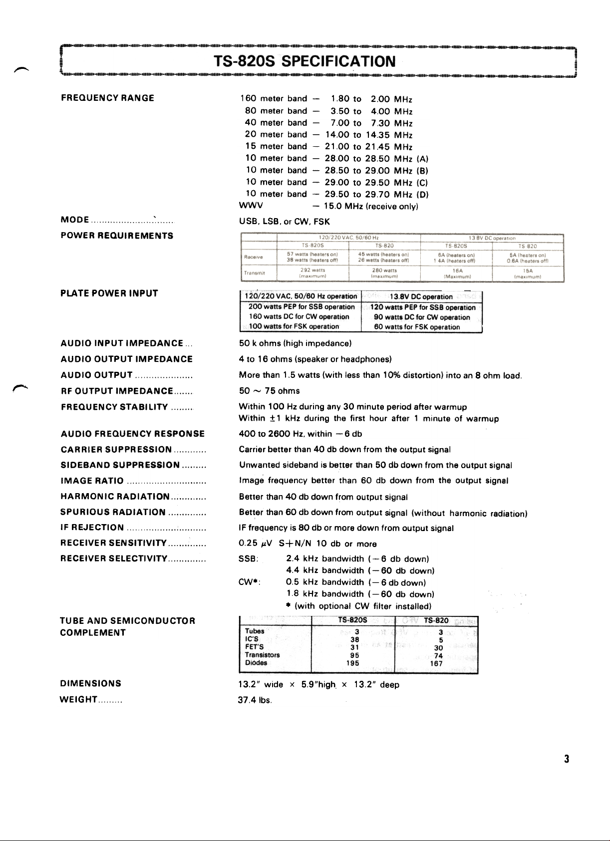
FREQUENCY RANGE
MOD E ~ POWER REQUIREMENTS
PLATE POWER INPUT
AUDIO INPUT IMPEDANCE ...
AUDIO OUTPUT IMPEDANCE
AUDIO OUTPUT RF OUTPUT IMPEDANCE., FREQUENCY STABILITY,
160 meter band -1.80 to 2.00 MHz
80 meter band -3.50 to 4.00 MHz
40 meter band -7.00 to 7.30 MHz
20 meter band -14.00 to 14.35 MHz
15 meter band -21.00 to 21.45 MHz
10 meter band -28.00 to 28.50 MHz (A)
10 meter band -28.50 to 29.00 MHz (B)
10 meter band -29.00 to 29.50 MHz (C)
10 meter band -29.50 to 29.70 MHz (D)
WWV -15.0 MHz (receive only)
use. LSB. or CW, FSK
1120/220 VAC. 50/60 Hz operation
200 watts PEP for sse operation
160 watts DC for CW operation
~at!! for FSK operation
13BV DC operation
120 watts PEP for sse operation
90 watts DC for CW operation
60 watts for FSK operatio~-
50 k ohms (high impedance)
4 to 16 ohms (speaker or headphones)
More than 1.5 watts (with less than 10% distortion) into an 8 ohm load.
50 ~ 75 ohms
AUDID FREQUENCY RESPONSE
CARRIER SUPPRESSION SIDEBAND SUPPRESSION IMAGE RATIO. HARMONIC RADIATION SPURIOUS RADIATION IF REJECTION , RECEIVER SENSITIVITY RECEIVER SELECTIVITY
TUBE AND SEMICONDUCTOR
COMPLEMENT
DIMENSIONS
WEIGHT
Within 100 Hz during any 30 minute period after warmup
Within :.t 1 kHz during the first hour after 1 minute of warmup
400 to 2600 Hz. within -6 db
Carrier better than 40 db down from the output signal
Unwanted sideband is be~ter than 50 db down from the output signal
Image frequency better than 60 db down from the output signal
Better than 40 db down from output signal
Bet~er than 60 db down from output signal (without harmonic radiation)
I F frequency is 80 db or more down from output signal
0.25 JlV S+N/N 10 db or more
SSB: 2.4 kHz bandwidth (- 6 db down)
4.4 kHz bandwidth (- 60 db down)
CW.: 0.5 kHz bandwidth (- 6 db down)
18kHz bandwidth (- 60 db down)
.(with optional CW filter installed)
1:o-tl205
Tubes
IC'S
FET'S
Transistors
DiOdes
38
31
95
195
3
30
74
167
3
5
13.2" wide x 5.9"high x 13.2" deep
37.4 Ibs.
3
~
SECTION 1. FEATURES
1. Pll System, HF Band SSB!CW!RTTY
Transceiver
This transceiver employs newly developed PLl (Phase
Locked loop) circuit covering 1 8 to 29.7 MHz (WWV
15 MHz) for SSB, CW and ATTY operations
2. Minimum Spurious and Excellent Overload
and Crossmod. Characteristic
The adoption of FET balanced type mixer. MaS FET and
single conversion system minimizes spurious during
transmission and assures excellent overload and cross-
mod. characteristic during reception.
3. Built-in IF SHIFT Circuit
IF SHIFT circuit is built in the transceiver to shift IF pass
band without changing receive frequency The circuit is
also called the "pass band tuning circuir., It allows you
to eliminate radio interference or set the receive fre-
quency characteristic to the desired bandwidth simply
by manipulating one C<;Introl knob
4. Built-in RF Processor
The unique speech processor uses a quick time constant
at 455 kHz. Since this circuit is of RF type, it produces
little distortion and, unlike the clipper system, does not
deteriorate the tonal quality
5. RF NFB
RF NFB from the transmit final stage to the driver stage
improves the cross modulation distortion. The use of
the amplification type AlC further improves the quality
of transmit signals
6. Newly Designed Analog Dial
The combination of newly designed mono-scale and su-
b-dial provides easy reading of frequencies. The adop-
tion of a circuit that is completely free from changes in
carrier frequencies permits accurate indication of fre-
quencies on one dial pointer.
7. Digital Display Dial
The digital dial of TS-820S indicates transmit and
receive frequencies using carrier. VFO and local oscillator signals instead of converting VFO frequencies.
Thus. accurate frequencies can be read at all times at
any band and any operating mode.
Since the accuracy of frequencies is set up only by the
10 MHz standard oscillator. frequencies can be read accurately up to 100 Hz order by calibrating the oscillator
with WWV.
The green indication on the dial assures many hours of
fatigue less operation
8. D.H. (Displav Hold) SWITCH
BV pressing the DH switch. the frequency read on the
digital remains on. thus serving as a memory system
9. Rigid Structure and Easy Operation
The transceiver is built with a die casting front panel
and a rigid chassis, providing outstanding mechanical
stability for mobile operation All the operating parts
such as control knobs and dials are designed and arran-
ged according to human engineering technology to en-
sure maximum case of operation
10. Monitor Circuit
The monitor circuit allows you to hear your own voice
during transmission. which is normally impossible with
collventional transceivers This is very useful when
checking the modulation condition or adjusting tho AF
processor
11. Selector Switch for SSB/CW Receive
Frequency Response
During CW reception the audio frequency response IS
automatically narrowed to improve the clarity of sound.
12. Build-in Fixed Channel Circuits with AIT
(crystals are optionall
The fixed channel circuits with AIT permit the Uie with
the built-in VFO for more enjoyable operation
13. Transverter Connector
Transverter TV-502 (2m) can be connected for ready
operation. Changeover to HF or VH F is accomplished
automatically with the power switch of the transverter.
14. ,Built-in AC Power Supply. and DC Operation with
Optional DC-DC Converter
DC- DC Converter DS-1 A (option) can be attached to
the transceiver for mobile operation.
16. Wide Variety of Auxiliary Circuits
and Devices
The transceiver is completed with a noise blanker
circuit, VOX circuit, side tone circuit, marker cIrcuit,
built-in speaker. 3-position AGC switch, heater swItch.
IF OUT terminal and linear terminal
The following devices are available as optional extra:
Remote VFO (VFO-820), CW Filter (YG-88CI, Digital
Display (DG-1 AI. Transverter (TV-502S). Microphone
(MC-50), Low Pass Filter (Lf-30A)
"
4
'" :
---
2.1 UNPACKING
Remove the TS-820S from its shipping box and packing
material and examine it for visible damage. If the equipment
has been damaged in shipment. save the boxes and packing
material and notify the transportation company immediately. It is a good idea to save the boxes and packing material
in any case because they are very useful for shipping or moving the equipment.
The following accessories should be included with the transceiver:
1 Operating Manual
1 Microphone Plug
1 Jumpered 9-pin Plug (installed)
5 RCA Phono Plugs
1 Alignment Tool
2 Plastic Extension Feet
with Screws
1 AC Power Cord
1 Speaker Plug
1 8P US Plug
4 Fuse (6A x 2, 4A x 2) .
2.2 OPERATION LOCATION
As with any solid state electronic equipment the TS-820S
should be kept from extremes of heat and humidity.
Choose an operating location that is dry and cool. and avoid
operating the transceiver in direct sunlight. Also. allow at
least 3 inches clearance between the back of the equipment
and any object. This space allows an adequate air flow from
the ventilating fan to keep the transceiver coo).
2.3 POWER CONNECTIONS
Make sure the POWER switch on the front panel of the
TS-820S is turned oft. the stand-by switch is put in the REC
position. and that the voltage switch on the back of the
TS-820S is switched to the correct line voltage (120 or 220.)
Connect the POWER cord to an appropriate external power
source.
2.4 ANTENNA
Connect a 50 ~ 75 ohms antenna feedline to the coaxial
connector on the rear panel.
Fixed Station -Any of the common antenna systems designed for use on the high frequency amateur bands may be
used with the TS-820S. provided the input impedance of the
transmission line is not outside the capability of the pi-output matching network. The transmission line should be of
the coaxial cable type. An antenna system which shows a
standing wave ratio of less than 2 : 1 when using 50 or 75
ohm coaxial transmission line. or a systerp that results in a
transmission line input impedance that is essentially resisti-
ve. and between 15 and 200 ohms will take power from the
transceiver with little difficulty. If openwire or balanced type
transmission line is used with the antenna. a suitable antenna tuner is recommended between the transceiver and
the feed line. Methods of construction and operating such
tuners are described in detail in the ARRL Antenna Handbook. and similar publications. For operation on 75 and 40
meter bands. a simple dipole antenna. cut to resonance in
the most used portion of the bands. will perform satisfacto-
rily. For operation of the transceiver on the 10. 15. and 20
meter bands. the efficiency of the station will be greatly increased if a good directional rotary antenna is used Remember that even the most powerful transceiver is useless
without a proper antenna.
Mobile Station -Mobile antenna installations are critical.
since any mobile antenna for use on the high frequency
bands represents a number of compromises. Many amateurs lose the efficiency of their antenna through improper
tuning. Remember the following points when using the
tS-820S with a mobile antenna.
The "Q" of the antenna loading coil should be as high as
possible. There are several commercial models available
which use high "Q" coils.
The loading coil must be capable of handling 1tle power of
the transceiver without overheating. In the CW mode the
power output of the transceiver will exceed 80 watts.
The SWR bridge is a useful instrument. but unfortunately it
is quite often misunderstood. and overrated in importance.
Basically. the SWR bridge will indicate how closely the antenna load impedance matches the transmission line With
long transmission lines. such as will be used in many fixed
station installations. it is desirable to keep the impedance
match fairly close in order to limit power loss. This is parti-
cularly true at the higher frequencies. The longer the line.
and the higher the frequency. the more important SWR becomes. However. in mobile installations the transmission
line seldom exceeds 20 feet in length. and an SWR of even
4 to 1 adds very little power loss. The only time SWR will
indicate a low figure is when the antenna presents a load
close the 50 ohms. but many mobile antennas will have a
base impedance as low as 15 or 20 ohms at their resonant
frequency. In such a case, SWR will indicate 3 or 4 to 1,
and yet the system will be radiating efficiently.
The really important factor in your mobile antenna is that is
should be carefully tuned to resonance at the desired fre-
quency. The fallacy in using an SWR bridge lies in the fact
that it is sometimes possible to reduce the SWR reading by
detuning the antenna. Field strength may actually be reduced in an effort to bring SWR down. Since field strength is
the primary goal. we recommend a field strength meter for
antenna tuning.
5
For antenna adjustments. the transceiver may be loaded
lightly. using the TUN position instead of operating at full
power output. This will limit tube dissipation during adjust-
ments. and will also help to reduce interference on the fre-
quency In any case. do not leave the transmitter on for very
long at one time Turn it on just long enough to tune and
load. and get a field strength reading. Start out with the antenna whip at about the center of its adjustment range. Set
the VFO to the desired operating frequency and then adjust
the PLATE control for a dip. and then the LOAD control
Then observe the field strength' redding The field strength
meter may be set on top of the dash. on the hood. or at an
elevated location some distance from the car.
Change the whip length a half inch. or so at a ti.me. retune
the finals each time. and again check the field strength at the
antenna. Continue this procedure until the point of maxi-
mum field strength is found. This adjustment will be most
critical on 75 meters. somewhat less critical on 40. until on
10 meters the adjustment will be quite broad. After tuning
the antenna to resonance. the finals can be loaded to full power.
2.5 MICROPHONE
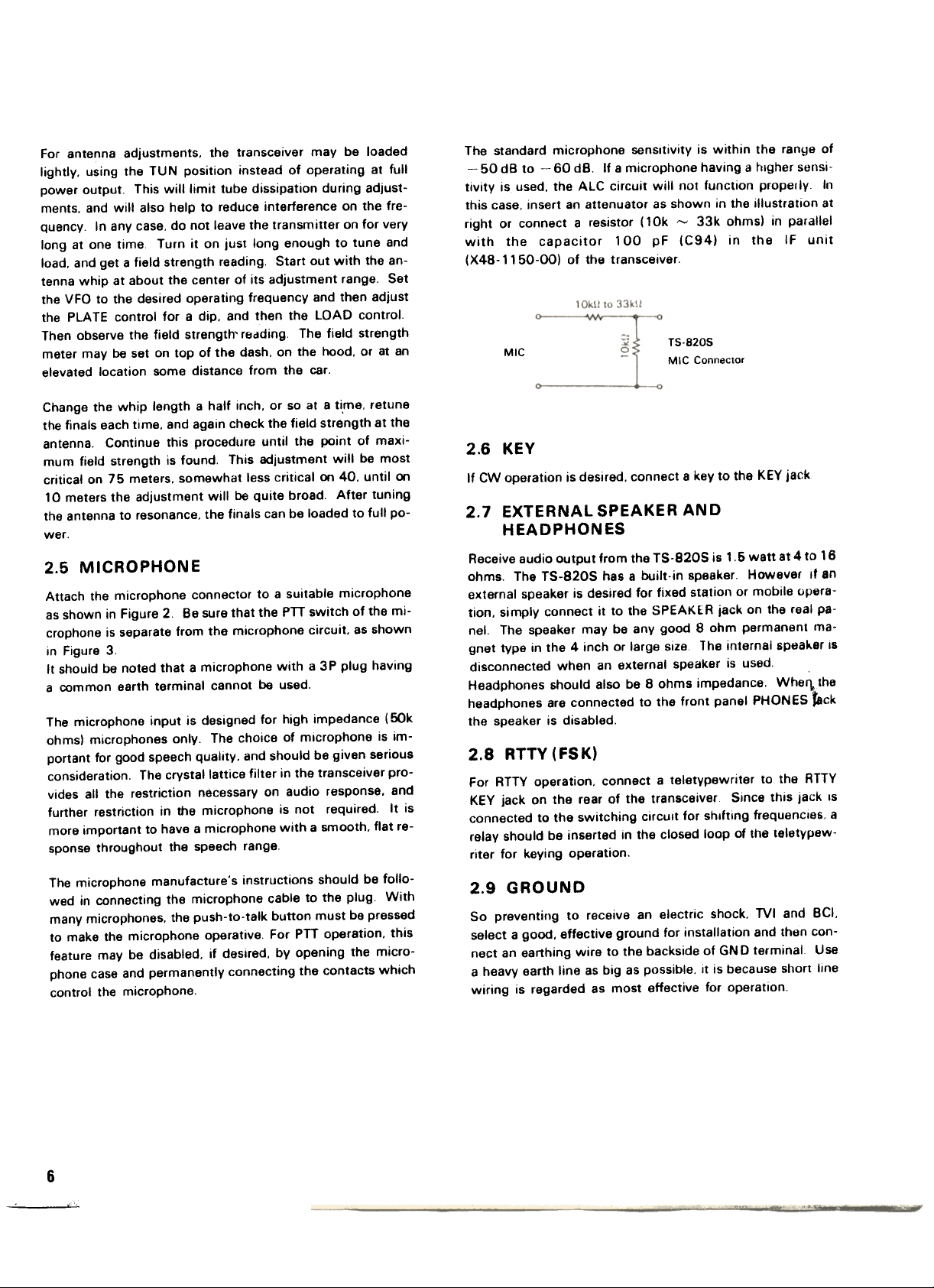
Attach the microphone connector to a suitable microphone
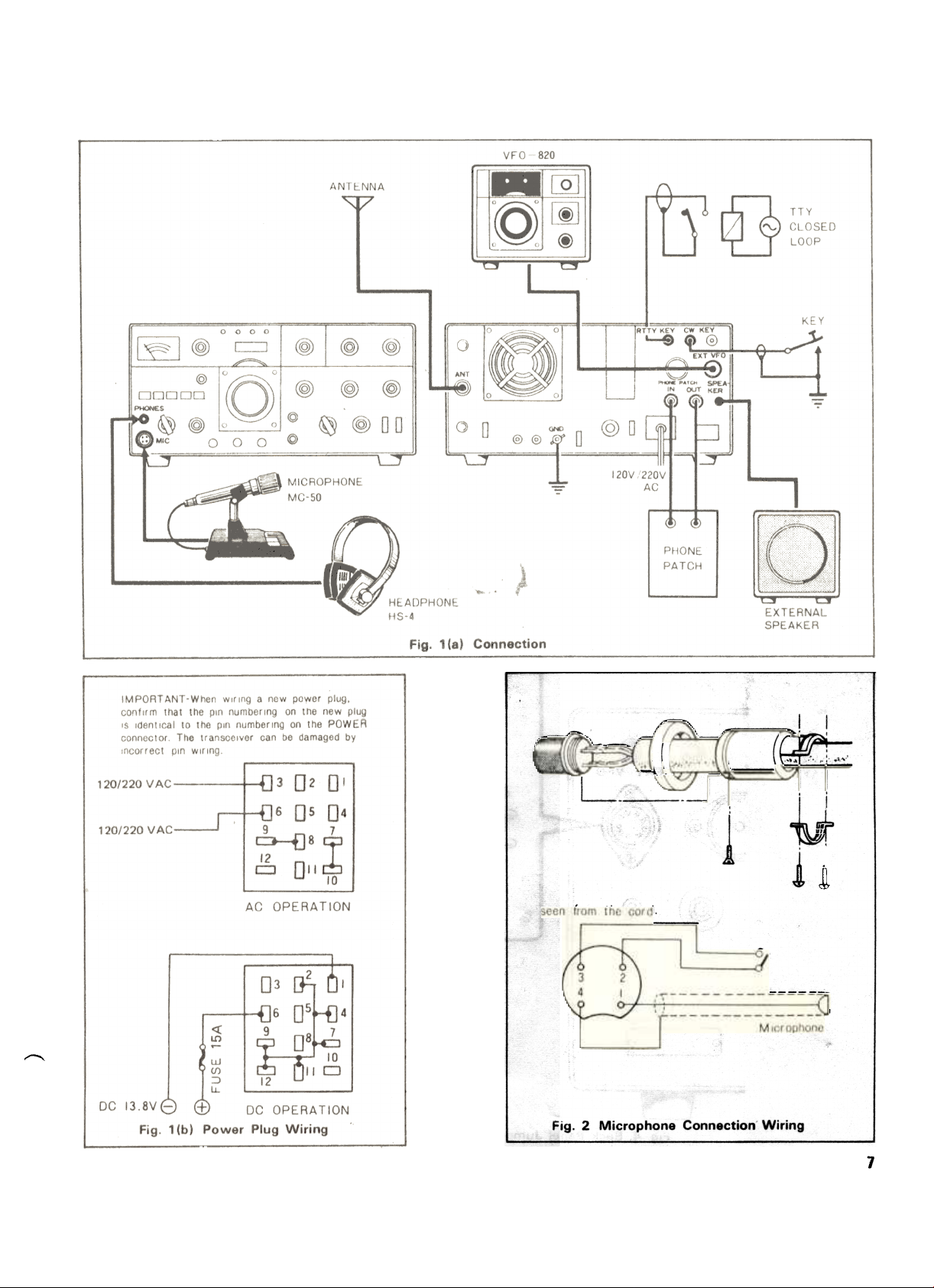
as shown in Figure 2 Be sure that the PTT switch of the mi-
crophone is separate from the microphone circuit. as shown
in Figure 3.
It should be noted that a microphone with a 3 P plug having
a common earth terminal cannot be used.
The microphone input is designed for high impedance (50k
ohms) microphones only. The choice of microphone is important for good speech quality. and should be given serious
consideration. The crystal lattice filter in the transceiver provides all the restriction necessary on audio response. and
further restriction in the microphone is not required. It is
more important to have a microphone with a smooth. flat re-
sponse throughout the speech range.
The microphone manufacture's instructions should be followed in connecting the microphone cable to the plug With
many microphones, the push-to-talk button must be pressed
to make the microphone operative For PTT operation, this
feature may be disabled, if desired, by opening the microphone case and permanently connecting the contacts which
control the microphone.
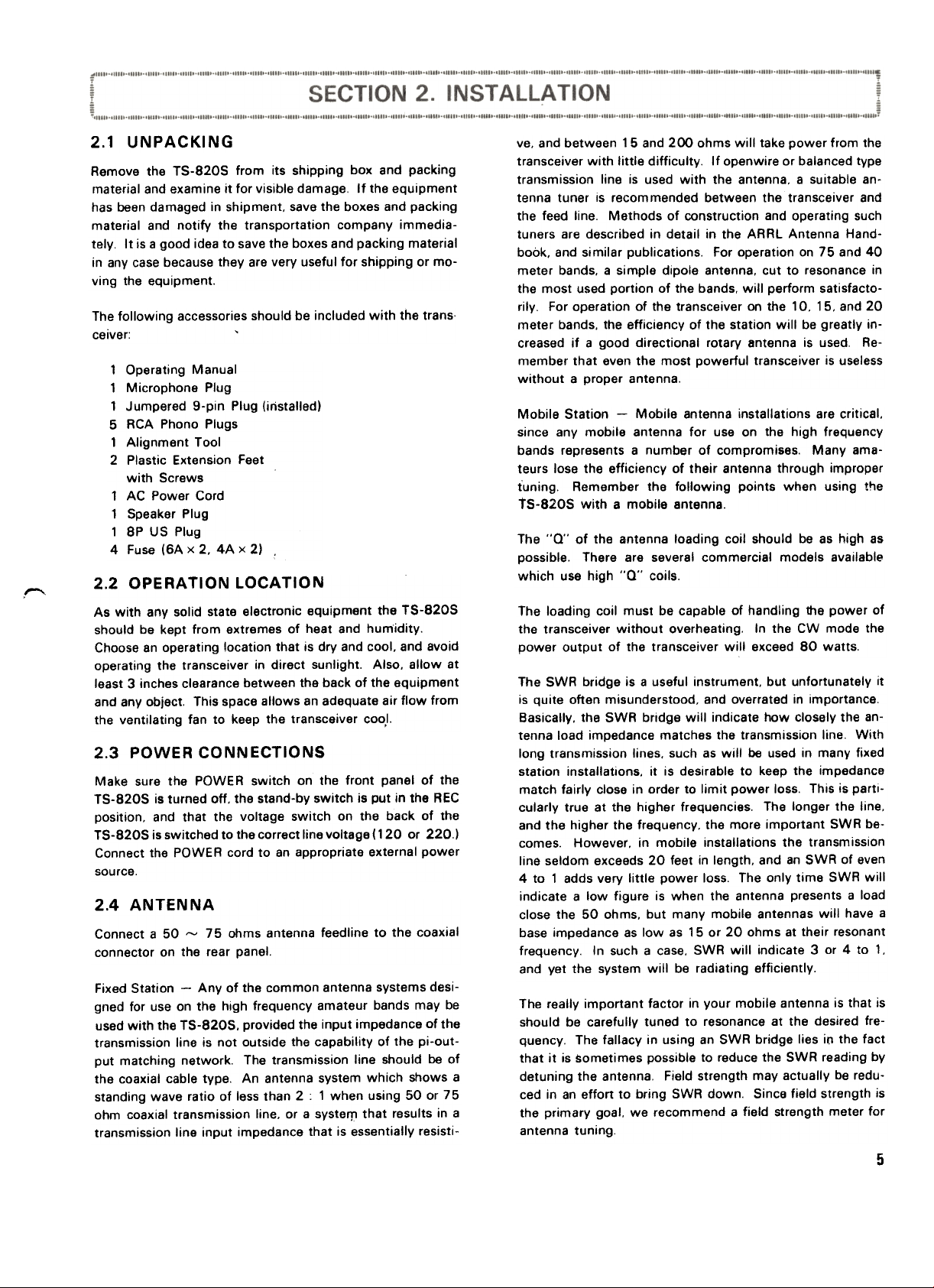
The standard microphone sensitivity is within the range of
-50 dB to -60 dB. If a microphone having a higher sensi-
tivity is used. the AlC circuit will not function properly In
this case. insert an attenuator as shown in the illustration at
right or connect a resistor (10k ~ 33k ohms) in parallel
with the capacitor 100 pF (C94) in the IF unit
(X48-1150-00) of the transceiver.
MIC
TS-820S
MIC Connector
2.6 KEY
If CW operation is desired. connect a key to the KEY jack
2.7 EXTERNAL SPEAKER AND
HEADPHONES
Receive audio output from the TS-820S is 1.5 watt at 4 to 16
ohms. The TS-820S has a built-in speaker. However If an
external speaker is desired for fixed station or mobile operation. simply connect it to the SPEAKER jack on the real pa-
nel. The speaker may be any good 8 ohm permanent ma-
gnet type in the 4 inch or large size The internal speaker IS
disconnected when an external speaker is used.
Headphones should also be 8 ohms impedance. Whel"l.the
headphones are connected to the front panel PHONES Jack
the speaker is disabled.
2.8 RTTY (FSK)
For ATTY operation. connect a teletypewriter to the ATTY
KEY jack on the rear of the transceiver Since this Jack IS
connected to the switching circuit for shifting frequencies. a
relay should be inserted in the closed loop of the teletypew-
riter for keying operation.
2.9 GROUND
So preventing to receive an electric shock. TVI and BCI.
select a good. effective ground for installation and then connect an earthing wire to the backside of GND terminal Use
a heavy earth line as big as possible. It is because short line
wiring is regarded as most effective for operation.
6
"..
-\
=
L
~
1 .
~
Fig. 2 Microphone Connection Wiring
7
-(b~:f{l
---
8
0_""-
~,."-"". -,"
~
1
~
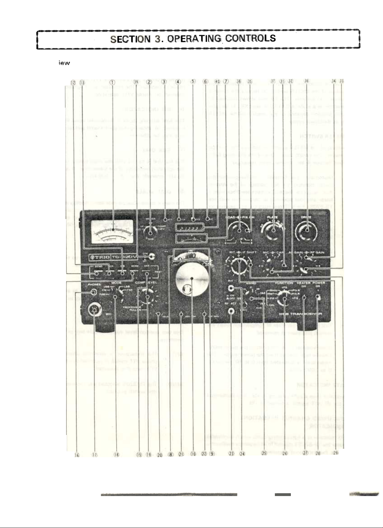
3.1 FRONT PANEL CONTROLS
CD METER
The meter monitors six different functions. depending on
the position of the METER switch. In receive the meter is
automatically an 5-meter The 5-meter shows received signal strength on a scale of 0 to 40 db over 59 In transmit
the meter function depends on the position of the METER
switch. as described below
~ METER SWITCH
VFO INDICATOR
@
The VFO indicator is a light emitting diode which illuminates
whenever the TS-820S's internal VFO is controlling the trans-
ceiver's operation. The indicator is not lighted during fixed
channel, or remote VFO. operation
RIT INDICATOR
@
This light emitting diode is illuminated when the RIT circuit
is turned on. showing that the transmit and receive frequencies may be different
The position of the METER switch determines the function
of the meter The switch selects one of the following func-
tions (see Section 4 for nominal meter readings):
ALC
IP
RF:
caMP:
HV
(Automatic Level Control) -In thIs position the
meter monitors the ALC voltage of the internal
ALC circuit (or the AlC voltage feedback from a
linear amplifier operated in conjunctIon with the
TS-820S). For SSB operation the ALC reading for
voice peaks shquld be within the indicated ALC
range of the meter. The ALC voltage adjustment
is made with the MIC control for SSB and with
the CAR control for CWo
(Plate Current) -In this position the meter monitors the plate current of the final tubes. The meter scale is calibrated from 0 to 350 ma.
(Output Power) -In this position the meter mo-
nitors the relative output power of the transcei-
ver. There is no meter scale for this Rosition.
Normally the reading should be adjusted with the
RF VOLT control for a 2/3 scale meter reading.
This indicates the state of compression when the
speech processor is operated.
(High Voltage) -In this position the meter monitors the high voltage from the power supply. The
meter scale is calibrated from 0 to 10. indicating
0 to 1000 volts.
SUB-DIAL
<1)
The sub-dial is turned with the main tuning knob to select
the operating frequency of the transceiver It is calibrated at
50 kHz intervals from 0 ~ 500 kHz.
@ DIAL SCALE
The unique mono-scale permits direct reading of frequencies
over the range of 0 to 500 kHz graduated at 1 kHz irller-
vats. Operating frequency can be obtained by adding the
frequency read on the dial to the frequency (MHz) indIcated
on the BAND switch.
(ii DIAL CALIBRATE KNOB
This knob is used to calibrate the reading on the dial scale.
It should not be used for turlll\g purposes
@ MAIN TUNIG KNOB
This knob turns the VFO and dial scale to select the fre-
quency to be added to the bslld frequency to establish the
transceiver's operating frequency
@ STAND-BY SWITCH
This two position lever switch selects one of the following
functions
REC:
The transceiver is receiving unless the microphone PTT switch is switched to transmit, or the
VOX circuit is activated.
~
-
@ ATT INDICATDR
This indicator uses a light emitting diode. It is illuminated
when the RF A TT switch is turned to ON
FIX (FIXED CHANNEL OPERATION)
@
INDICATOR
The FIX indicator is a lightemltting diode which illuminates
whenever the TS-820S's internal fixed frequency oscillator is
controlling the transceiver's operation
10
SEND
The TS-820S is locked into the transmit mode in
this switch position.
@ VOX SWITCH
This two-position lever switch selects one of the following
functions.
MAN
With the switch in this position. the transceiver is
switched into transmit or receive by the stand-by
switch or the PTT switch on the microphone.
TUN
Used for adjustment of transmit conditions. The
input power to the final stage is low as compared
with that for CW so that the final stage tubes can
be protected against damage due to overloading
during adjustment. Since the KEY circuit is inoperative in the TUN mode, the transceiver cannot
be used for transmission or reception.
vox
@
With the switch in this position. the VOX circuit is
turned on for voice operated transmit on. SSB semi-automatic break-in operation on CWo
NB SWITCH
off. The noise blanker is designed to reduce pulsating ignition type noises. When the lever switch is flipped up. the
circuit is turned on.
@ MONI (MONITOR) SWITCH
This switch is used to demodulate part of the output of the
transmit IF amplifier for monitoring transmit signals.
@ AGC SWITCH
The AGC switch controls the AGC (Automatic Gain Control)
circuit giving the operator three choices:
OFF: It may be desirable to turn the AGC off when re-
ceiving a very weak signal.
FAST:
The FAST AGC position is designed for use in CW
operation.
SLOW:
Use the SLOW AGC position for SSB operation
@ PHONES JACK
CW:
use
Used for CW operation
Used for USB operation It is internationally de.
termined that the 14. 21 and 28 MHz bands be.
long to USB.
LSBThe NB switch turns the built-in noise blanker circuit on and
Used for LSB operation. It is internationally determined that the 3.5 and 7 MHz bands belong to
LSB.
For RTTY operation with teletypewriter.
@) COMP lEVEL KNOB
Pull this knob during sse operation. The speech processor
is activated and the talk-power is increased. Adjust the
state of compression by turning the knob while observing
the COMP meter.
@ DELAY KNOB
The DELAY control adjusts the holding time of the VOX cir-
cuit for VOX or break-in CW operation. The control will have
to be adjusted to the preference of the individual operator.
@ ANTI VOX KNOB
This control adjusts the level of the anti VOX signal fed in to
the VOX circuit. Adjust the control to prevent feedback of
the speaker from tripping the VOX circuit.
The headphones jack allows use of a 4 to 16 ohm set of
headphones with a 1/4" phone plug attached. When the
phones are plugged into the transceiver. the speaker is disconnected.
@ MIC CONNECTOR
The microphone connector is four pronged. allowing use of
the PTT microphone. Figure 2 shows how to wire the plug
on the microphone cable.
@ MODE SWITCH
The MODE switch is used for selection of type of waves or
for TUNE operation.
@ VOX GAIN KNOB
This control adjusts the sensitivity of the VOX circuit by ad-
justing the gain of the VOX amplifier. for voice controlled
operation.
@ RF ATT SWITCH
With this switch set to ON. ATT (attenuator) of about 20 dB
is connected to the antenna circuit. protecting the RF amplifier and mixer circuit from strong input signals.
@ RIT SWITCH
This is the switch for the AfT (receiver incremental tuning)
circuit To turn on the circuit, press this switch; to turn off,
press it once again. The AIT indicator is illuminated when
11
~
the RIT circuit is ON By turning the RIT knob. the receive
frequency of VFO can be changed by :t3 kHz and the fre-
quency of fixed channel by :t 150 Hz without changing the
transmit frequency.
@ BAND SWITCH
This 11-position switch selects all the necessary circuits to
tune the transceiver to the desired 500 kHz band.
fixed channel crystals are installed in the transcei.
verI.
@ H. SW (HEATER) SWITCH
This switch turns the heater circuits of the three transmitting
tubes on and off. The heaters would normally be turned to
OFF to reduce power consumption in mobile or portable re-
ceiving.
@ FUNCTION SWITCH, ,
This 7 -position rotary switch selects one of the following
transceive functions.
GAL
FIX:
CAL.
RMT
CAL25 kHz:
This position allows calibration of the 1"5-8205'5
internal VFO to one of the transceiver's fixed fre-
quency channels (if an optional fixed channel crystal is installed), With the switch in this position a
signal is generated at the selected fixed channel
frequency and the main tuning knob can be tuned
to zero beat the calibrating signal,
This position alloWs calibration of the VFO-820
(remote VFO) to the transceiver's operating fre-
quency. With the switch in this position. the
transceiver generates a calibrating signal and the
VFO-820 can be tuned to zero-beat the calibra-
ting signal.
With the switch in this position. the transceiver's
calibrator circuit generates a marker signal at
every 25 kHz for normal calibration of the internal
VFO.
VFO:
The switch is kept in this position for normal
transceive operation.
~~ POWER SWITCH
The POWER switch turns all the power on and off in
TS-8205.
@ RIT KNOB
This knob is used to change receive frequency when the AIT
circuit is in operation Set the center position (0) of the
AIT knob to the AIT -OFF.
@ IF SHIFT KNOB
By using this knob during reception. the center frequency of
the IF crystal filter can be shifted by :t 17 kHz. facilitating
the adjustment of the tonal quality of receive signal or elimi-
nating radio interference from nearby frequencies. For normal operation. this knob should be set to the center position
(click is heard).
(:j~ MIC GAIN KNOB
This knob is used for adjustment of the gain of MIC amplifier
during sse operation. Adjust so that the meter pointer does
not deflect beyond the ALC lone.
@ CAR (CARRIER) LEVEL KNOB
Used to adjust carrier level during CW operation. Adjust so
that the meter does not deflect beyond the ALC lond.
VFO.R
FIXR:
FIX:
12
With the switch in this position. the TS.820S's internal VFO controls the receive function and the
internal fixed channel oscillator controls the trans-
mit function (if fixed channel crystals are installed
in the oscillator).
With the switch in this position, the TS-820S's internal VFO controls the transmit function and the
built-in fixed channel oscillator controls the receive function (if fixed channel crystals are installed in the oscillator) The VFO.R and FIX.R allow
cross-channel operation without an external VFO.
With the switch in this position. the IS-820S's
fixed channel oscillator controls the transmit and
receive function of the transceiver (if accessory
@ AF GAIN KNOB
This knob adjusts the gain of the receiving audio amplifier
The audio volume of the received signal increases as the
control is turned clockwise.
@ RF GAIN KNOB
This control adjusts the gain of the receiver sections RF am-
plifier. Turn the knob fully clockwise for maximum gain and
for a correct S-meter reading Turn the control counter--
clockwise to reduce the gain.
@ FIX CH (FIXED CHANNEL) SELECT SWITCH
This four-position rotary switch selects between four diffe-
rent fixed frequency channels which can be installed Inside
-
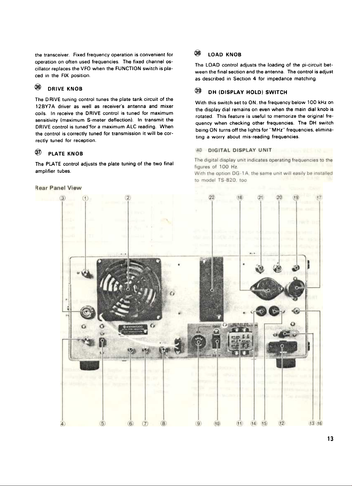
the transceiver. Fixed frequency operation is convenient for
operation on often used frequencies. The fixed channel oscillator replaces the VFO when the FUNCTION switch is placed in the FIX position.
@
DRIVE KNOB
The D RIVE tuning control tunes the plate tank circuit of the
12 BY7 A driver as well as receiver's antenna and mixer
coils. In receive the DRIVE control is tuned for maximum
sensitivity (maximum S-meter deflection). In transmit the
DRIVE control is tuned'for a maximum ALC reading. When
the control is correctly tuned for transmission it will be cor-
rectly tuned for reception.
@
PLATE KNOB
The PLATE control adjusts the plate tuning of the two final
amplifier tubes.
@
LOAD KNOB
The LOAD control adjusts the loading of the pi-circuit bet-
ween the final section and the antenna. The control is adjust
as described in Section 4 for impedance matching.
@
DH (DISPLAY HOLD) SWITCH
With this switch set to ON, the frequency below 100 kHz on
the display dial remains on even when the main dial knob is
rotated This feature is useful to memorize the original frequency when checking other frequencies. The DH switch
being ON turns off the lights for "MHz" frequencies, elimina-
ting a worry about mis-reading frequencies.
13

3.2 REAR PAN EL CONTROLS
CD RFVOLT
Use the RF VOLT control to adjust the sensitivity of the RF
output function of the meter. Adjust it for a 2/3 scale rea-
ding during CW transmission.
@ COOLING FAN
This fan cools the RF amplifier section of the TS-820S to in-
sure reliable and efficient opera'tion.
@ ANTENNA CONNECTOR
This SO-239 coax connector should be attached to a suita-
ble antenna for transmitting and receiving See Section 2.4
for a discussion of an appropriate antenna.
@ BIAS CONTROL
The BIAS control adjusts the bias voltage of the two
S2001A (6146B) amplifier tubes. Tuning the control clock-
wise increases the idling plate current of the tubes. Section
4 describes adjustment of ~he bias current.
@ SG SWITCH
The 5G slide switch controls the screen grid voltage o.n the
final tubes. For tuning or neutralizing the TS-8205 you can
set the switch to the OFF position Turn the switch back to
the ON position for normal operation The 5G voltage is on
when the switch is up and off when the switch is down.
@ TRANSVERTER IN JACK
This is the RF input jack for input from a VHF transverter.
(j) TRANSVERTER OUT JACK
This is the low level RF output jack for use with a VHF trans.
verter
@ GND (GROUND) LUG
To prevent accidental shocks from the chassis. as well as in-
terference. connect a good earth ground to this lug.
When the position of the AC Voltage Selector Switch is
changed. it is also necessary to change the power fuse for
120 volt operation a 6 ampere fuse, for 220 volt operation a
4 ampere fuse provided with the TS-820S should be used.
@ AC VOLTAGE SELECT SWITCH
This slide switch switches the primary of the power transfor
mer to select 120 or 220 VAC operation.
POWER SUPPLY CONNECTOR
C!~
This 12-pin connector is used to connect an AC or DC power
source to the transceiver.
TRANSVERTER CONNECTOR
~2)
This 12 -pin connector is used to control an accessory VH F
transverter.
@ X VERTER SWITCH
When VHF Transverter (TV-502S) is connected to the trans
ceiver, the selection of H F or VH F IS automatically accom
plished by setting the transverter switch to ON or OFF.
@ PHONE PATCH IN JACK
This is a phone patch input terminal for transmission of
SSTV or other line inputs.
\1~ PHONE PATCH OUT JACK
This is a line output terminal for phone patch or recording. It
is also used for connection to the input of FSK demodulator
SSTV.
(~
@ FUSE
This fuse is a JAG. 4 amp fuse which protects the power
supply of the transmitter against short circuits. Never use a
higher amperage fuse than the one specified. An improper
one can cause extensive damage to the transmitter. When
the fuse blows out. try to determine the cause before repla-
cing it.
14
SPEAKER JACK
The receiver audio output can be connected through this
jack to the external 4 to 16 ohm speaker. The internal
speaker is disconnected when an external speaker is connected
~

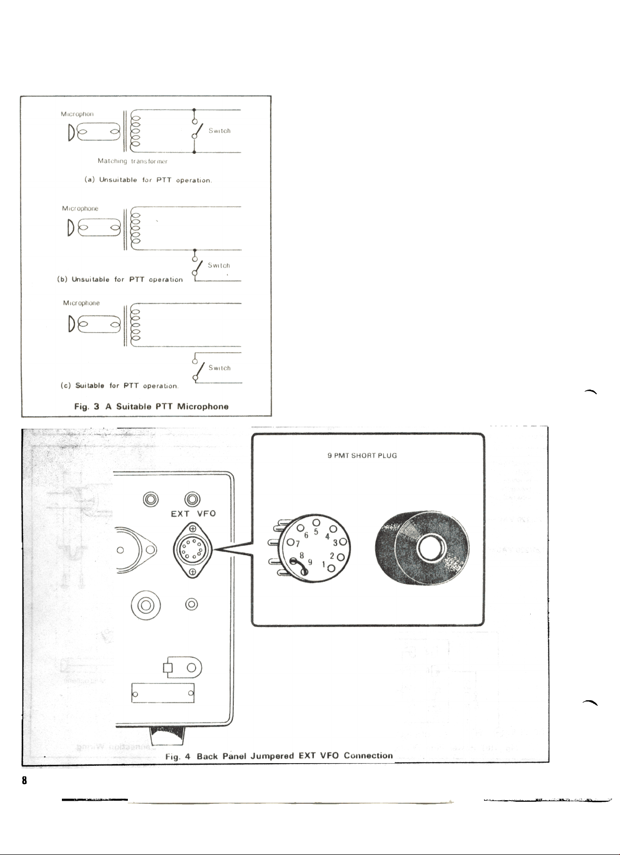
@ EXTERNAL VFO CONNECTOR
This 9-pin connector provides a means of interconnecting
the KENWOOD VFO-820. another external VFO. or an external receiver. The interconnecting cable is provided with
the VFO-820. The 9-pin jumpered VFO plug provided with
the TS-820S must be inserted in this socket for normal
transceiver operation.
@ REMOTE CONNECTOR
The REMOTE connector is an 8-pin socket for use in inter-
connecting a linear amplifier. an external speaker. or another
accessory item. (See Fig. 30)
@) IF OUT JACK
Receive signals from the final I F stage are supplied to this
jack for monitoring waveforms of opposite stations.
Frequency 8.83 MHz
Output Approx. 0.67 Vrms. (ANT input more than
3JlV. load resistance 4.7 kO)
@ CW KEY JACK
Connect a key to this 1/4" phone jack for CW operation
Key opened terminal voltage approx. -65V.
@ RTTY KEY JACK
This is used for FSK operation. A 2P plug should be inserted
for connection to the switching circuit of a teletypewriter.
@ DC-DC CONVERTER CONNECTING HOLE
DC-DC Converter (DS-1 A. option) can be wired through this
hole. For wiring. remove the cover plate.
15

i SECTION 4. OPERATING INSTRUCTIONS ,
'_Nt .ouo... 0 nil 0., HI". ouu 0 nuo.o IIU'. ..HI'. 01t'0 o. 0 no.. 0_. oHllO ..u 0 p. oUU o. ouu o. "UI'. ouop O U' ._."""._.0 o ,_Nt. u
4.1 PRELIMINARY PROCEDURE
Set the MIC and CAR controls to zero and the MODE switch
to LSB. USB. or CW to prevent accidental transmit conditions before tuning. The TS-820S must be operated into a
50 ~ 75 ohm antenna or dummy load with an SWR less
than 2 : 1. Random length wire antennas or light-bulb dum-
my loads cannot be used, Conventional half-wave dipoles
and beam antennas should only be used at or near their
resonant frequency. Exceeding an SWR of 2: 1 can
damage the components in the output stage of the
transceiver,
Be sure to complete all of the required cabling. as described
in Section 2.3 " 2.8.
With a suitable antenna and microphone (or key) connected
to the transceiver. set the T5-8205 switches to positions des-
cribed in Table 1
4.2 RECEIVER TUNING
Refer to Table 1 for the initial switch settings of the T5-8205
for receiving. and then continue with the described procedure.
Push the POWER switch on. The meter. dial scale. and VFO
indicator will light. indicating that the transceiver is operating The receiver section is fully solid-state allowing recep-
tion with the H SW switch turned to OFF Advance the AF
GAIN control clockwise until some receiver noise is heard in
the speaker Turn the main tuning dial within the frequency
range of the amateur band chosen until a signal is heard
Tune the signal for the clearest possible reception. and then
adjust the DRIVE control for maximum deflection of the S--
meter.
The RF GAIN control varies the AGC feedback voltage which
effects the S-meter reading. With the RF GAIN control fully
clockwise. the S-meter gives a proper signal strength rea-
ding Tuning the control counter-clockwise reduces the RF
GAIN. reducing signal strength and band noise
4.3 READING THE OPERATING
FREQUENCY
The frequency dial of T5-8205 indicates accurate carrier
positions regardless of operating modes because of the use
of a special circuit system. thus the transmit and receive frequency can be directly read on the dial. except for CW recep.
tion in which case the frequency on the dial is lower by the
beat frequency than the receive frequency
When the digital display is used.
If there is any difference between the frequencies on the dial
TABLE 1. Initial Switch Settings for Receiving
CONTROL LOCATION
FRONT PANEL CONTROLS
REAR PANEL CONTROLS
-
CONTROL
BAN D Switch
POWER Switch
H. SW Switch
Stand-by Switch
N B Switch
RIT Switch
RF ATT
FUNCTION Switch
AGC Switch
MODE Switch
PLATE Knob
DRIVE Knob
RIT Knob
AF GAIN Knob
IF SHIFT Knob
RF GAIN Knob
EXT VFO Connector
SG Switch
X VERTER Switch
The remaining controls do not affect reception so they may
be in any position.
-
Desired band
POSITION
OFF
OFF
REC
OFF
OFF
OFF
VFO
SLOW or FAST
To the appropriate sideband or CW
Middle of the range for the band
Centered
Centered
Fully counter-clockwise
Centered
Fully clockwise
The jumpered plug must be in this socket
ON (up position)
OFF
~
16

scale and the digital display. the correct frequency is on the
digital display In this case. the analog dial should be calibrated with the calibrate knob.
NOTE: When the digital display is used, the digits for
10 MHz order change according to the BAND switch and
are independent of the counter unit. In the 295 MHz band,
for example, the indication "29.9999" is followed by
,. 200000"
cw
Set the IF SHIFT knob to its center position. If CW filter is
not used, obtain a zero beat point of marker signal and turn
the main tuning knob counter-clockwise until a beat signal
of about 800 Hz is received. While holding the main tuning
knob, turn the dial calibrate knob so that the dial pointer in-
dicates the correct position on the dial.
When CW filter is used. turn the dial when the marker signal
casues maximum deflection on the S meter and then calibrate using the dial pointer. In this case. the beat frequency
is about 800 Hz (CW filter YG-88C is optional extra)
CALIBRATING THE FIXED CHANNEL AND
VFO FREQUENCIES
Fixed channel and VFO frequencies can be calibrated at the
CAL-FIX position of the FUNCTION switch. Set the switch
to the CAL-FIX position and turn the VFO main tuning knob
until a beat signal is received in the vicinity of fixed channel
frequency. Calibration is effected at the zero beat position
CALIBRATING THE TS-820S WITH VFO-820
Turn the FUNCTION switch to CAL-RMT to cal!brate the
T5-8205 with the VFO-820. a receiver. or another remote
VFO Tune the remote VFO to the frequency selected on the
T5-8205 and zero beat the generated marker signal. At zero
beat. the T5-8205 and remote VFO frequencies coincide.
4.4 CALIBRATING THE FREQUENCIES
To read frequencies correctly from the dial scale. the dial
must be calibrated previously using a 25 kHz marker. To ca-
librate. set the FUNCTION switch to CAL-25 kHz and the
AIT switch to OFF. Turning the AF ATT switch to ON reduces the incoming signal and the marker signal can be received more easily Detailed method of calibration is described
below.
sse
Set the MODE switch to use or LSe Marker signals are received at every 25 kHz so accurate calibration is possible
over the entire range of the dial.
With the transceiver set to your desired band, turn the main
tuning knob so that a beat signal can be received at every
25 kHz. Turning this knob further will cause the beat signal
to vary from high to low tone and finally become a zero
beat Accurate zero beat point is obtained by turning the IF
SHIFT knob in the "-" direction (for USe), and in the "+"
direction (for LSB). Stop turning the knob at the zero beat
point and rotate the dial calibrate knob alone while holding
the main tuning knob until the dial pointer indicates 0, 25,
50 or 75 on the dial.
The dial calibrate knob is forced against the main tuning
knob by means of a spring permit slip ro!ation with ease.
By calibrating the TS-820S for normal operation. as
described previously. the TS-820S can be used as a
frequency standard for calibrating the remote VFO.
4.5 RF GAIN
RF GAIN is controlled by changing the voltage of the AGC
circuit Adjust the RF GAIN knob so that the S meter does
not cause excessive deflection This minimizes the noise during reception and allows the S meter to indicate the correct
signal strength. For normal operation. this knob should be
turned fully clockwise for maximum sensitivity
4.6 RF ATT
If the transceiver is operated in a short-distance (within
several hundred meters) and strong signals of nearby frequencies are received. the wanted signals are blocked. Also.
if the wanted signals are very strong. the S meter is scaled
out In this instance. set the ATT switch to ON. The input
signals to the RF amplifier are attenuated by about 20 dB.
providing distortionless reception
4.7 RIT
By using the RIT knob, the receive frequency of VFO can be
shifted by about :t3 kHz and the frequency of fixed channel
by about :t 150 Hz without changing the transmit fre-
quency If the frequency of the opposite station is deviated.
your receive frequency can be set to the station by turning
the AIT switch to ON and using the AIT knob. The state of
17

AIT can be checked bh the indicator in the window of the
dial
4.8 IF SHIFT
By using the IF SHIFT knob during reception. the pass band
frequency of the crystal filter can be shifted by about
i 17kHz because of adoption of PLL (Phase Locked Loop)
circuit in the local oscillator circuit This is one of the major
features of TS-B20S and can be used in the following cases:
switch to SEND and check that the plate current (IP) is 60
ma. If the plate CUI rent is not correct. adjust the real !Janel
BIAS control for a correct 60 ma of idling current and return
the stand-by switch to REC.
CAUTION: If the plate current is very much higher than 60
ma do /lOt leave the stand-by switch on for more than a few
seconds Excessive plate current shortens the life of the fi-
nal tubes.
Adjustment of Tonal Quality and Interference Rejection
during SSB Reception.
When the transceiver is used in USB mode. turn the IF
SH I FT knob in the ..+.. direction and the lower frequen-
cies are cut out Turning the knob in the ..-" direction
cuts out the higher frequencies (these procedures are
reversed for LSB mode) Adjust the knob so that the to-
;.
-nal quality suits your listening preference The IF SHIFT
knob is also effective in eliminating interference when
the receive signals are superposed on nearby signals
Adjustment of Tonal Quality during CW Operation
2
For detailed descriptions, refer to Section 413 "CW
operation",
FSK (ATTY) Operation at 850 Hz Shift
3
For detailed descriptions, refer to Section 419 "ATTY
operation",
4.9 NOISE BLANKER
The T5-8205 has a sophisticated built-in noise blanker
designed to reduce ingition type impulse noise The noise
blanker IS particularly important for mobile operation. When
necessary. activate the noise blanker circuit by flipping the
NB switch up.
4.10 AGC (AUTOMATIC GAIN CONTROL)
Set the AGC switch to the position appropriate for the
received signal Generally for SSB reception set the AGC
switch to SLOW. for CW reception set the AGC switch to
FAST. and for reception of a very weak signal the switch
may be set to OFF
4.11 TRANSMITTER TUNING
Connect the T5-8205 to a 50 ohm du mmy load or a 50 ohm
antenna with an 5WR of less than 2 1 before making any
transmitter adjustments. The life of the final tubes is directly
related to the 5WR of the antenna and to the length of tu-
ning periods
Refer to Table 2 for the initial switch settings of the TS-820S
for transmitting Tune the main tuning knob to the desired
operating frequency
PLATE IDLING CURRENT (See Fig. 7)
Turn the main tuning knob to the desired operating fre-
quency within the amateuf band selected Flip the stand-by
DRIVE TUNING (See Fig 8)
Shift the METER switch to ALC and the MODE switch to
TUN and peak the ALC reading (maximum meter deflection)
with the DRIVE control The stand-by switch is in the SEND
position for adjustment.
NOTE: If there is no ALC reading indicated. increase the
CAR control until there is an ALC reading
PLATE TUNING (See Fig 8)
Turn the METER switch back to IP, leave the MODE switch
at TUN and flip the stand-by switch to SEND Quickly adjust
the PLATE control to dip the plate current (a minimum meter
reading) Return the stand-by switch to REC
NOTE: The TUNE position permits tuning of the finaltilok
circuit at reduced power without danger to the tubes With
the MODE switch io the TUN position, the screen voltage of
the finals is reduced to approximately 50% and the keying
circuit is shorted.
PLATE AND LOAD TUNING
CAUTION: When the MODE switch is in the CW position
the final tubes draw full plate current in transmit Final tube
life is directly related to the length of tune-up periods Do
not transmit with the tubes out of resonance for more than
10 seconds at a time
Turn the MODE switch to CW. turn the METER switch to RF.
and set the stand-by switch to the SEND position. Quickly
adjust the PLATE control and then the LOAD control alter-
nately to peak (maximum meter lit/flection) the power out.
put. If necessary. adjust the RF VOLT control on the rear pa-
nel to bring the output reading to about a 2/3 scale rrladlng.
NOTE 1: The ALC meter is less deflected at the ON positIon of the SG switch or at the CW poSition of the MODE
switch than at the OFF position or the TUN position of these
switches This indicates the normal state of RF NFB The
MIC knob and the CAR knob should be properly adjusted un
der normal transmit condItions.
NOTE 2: Transmission is not effet;ted at the WWV or AUX
position of the BAND switch If the transceiver is left in the
transmit mode over a few minutes, the driver tube 12 BY7 A
of the final stage may be dalnaged,
18
~

Table 2. Initial Switch Settings for Transmission
(The controls not described should be set as described in Table 1)
LOCATION
FRONT PANEL CONTROLS
REAR PANEL CONTROLS
CONTROL
BAN D Switch
POWER Switch
H. SW Switch
Stand-by Switch
MODE Switch
VOX Switch
MONI Switch
MIC Control
CAR Control
METER Switch
PLATE Control
DRIVE Control
FUNCTION Switch
RIT Switch
SG Switch
EXT VFO Connector
TABLE 3. Summery of Transmitter Tuning Procedures
POSITION
Desired band
ON
ON
REC
USB or LSB depending on selected band
MAN
OFF
Fully counter-clockwise ;'
Centered
Ip
Middle of the range for the band
Centered
VFO
OFF
UP (ON)
Jumpered plug inserted .
19

4.12 SSB OPERATION
Tune the TS-a20S as described in Sections 41 to 4.11. Set
the MOOE switch to USB or LSB and connect a microphone
to the MIC connector
NOTE: International amateur practice dictates using use
or LSB on the following bands
Key the transmitter and speak Into the microphone with the
tone of voice used in normal operation. Adjust the MIC control until voice peaks are just within the top limit of the ALC
range printed on the meter scale. The METER switch is in
the ALC position If the transmitter section is driven beyond
this range. the transmitted signal will be distorted.
PTT OPERATION
By connecting the microphone equipped with PTT switch.
the transceiver is readily used for PTT operation. For communication. depress PTT switch with 5T ANDBY switch left
in the R EC position.
CW transmissions are automatically monitored through the
speaker of the transceiver. The audio gain of the sidetone
can be adjusted with VR3 on the AF board.
For semi-break-in operation. turn the VOX switch on Hold
the key down and increase the VOX GAIN control. until the
VOX relay just operates. It is desired to change the release
time constant of the VOX circuit. adjust the DELAY control
The plate current for CW operation should be about 200
ma. Use the CAR control to adjust the carrier level for CW
operation. At 200 ma of IP there may be 00 ALC readIng
OPERATION WITHOUT CW FILTER
Set the IF SHIFT knob to its center position and the AIT
switch to the OFF position to receive CW signal, Turn the
main tuning knob for about 800 Hz of beat signal and your
transmit frequency will be set to the transmit freqllency of
the opposite station (zeroing) During reception, the side
tone monitor is activated by pressing down the key In this
case. listen to the side tone signal and the receive signal and
adjust the main tuning knob so that the cycle of the sound is
increased, By so doing. the zeroirlg of frequencies can be
achieved After zeroing. set the Ril switch to ON and turn
the RIT knob for the pitch that suits your listening taste
When interference is encountered. turn the IF SHIFT knob
and the interference can be eliminated For more effective
CW operation. use the CW filter VG-88C (option) bV referring to page 34,
VOX OPERATION
Adjust the transceiver as des(;ribed in the previous paragraph. Flip the VOX switch on and close-talk Into the microphone. increasing the VOX GAIN control until the VOX relay
just operates. For VOX operation it is desirable to close-talk
the microphone to prevent background noises from tripping
the TS-820S into transmission.
Check that the ALC reading for voice peaks is still within the
ALC range on the meter. If necessary. adjust the MIC con-
trol for a proper ALC reading
If the VOX circuit is activ~ted by speaker noise. adjust the
ANTI-VOX control. Increase the control as necessary for
proper VOX operation.
Do not use more VOX GAIN or more ANTI VOX gain than
necessary to control VOX operation If the VOX circuit
transfers between words. or holds too long. adjust the release time constant by turning the DELAY control.
4.13 CW OPERATION
Tune and load the TS-820S as described in Sections 4.1
through 4.11. Connect a key to the back panel CW KEY
jack. set the MODE switch to CW, and set the stand-by
switch to SEND for transmitting
OPERATION WITH CW FILTER (OPTION)
Set the transceiver in the receive mode by setting the IF
SHIFT knob to the center position and the RIT switch to the
OFF position Adjust the main tuning knob for maximum de-
flection of the S meter. The pitch of the sound of the receive
signal will now be about 800 Hz. indicating that the zeroing
is completed.
Turn the AIT switch to ON and adjust the AIT knob for your
desired pitch of the sound. Also. adjust the IF SHIFT knob
for maximum signal strength.
OPERATION WITH DIGITAL DISPLAY
(TS-820S ONLY)
The digital display indicates the frequency of carrier signal
(BFa signal) so that the frequency indicated is deviated from
the transmit frequency of the opposIte station by the receive
beat frequency during CW reception (with IF SHIFT knob set
to its center position. the frequency indicated becomes lo-
wer)
To zero-in the frequencies with the digital display. set the
AIT switch to ON and turn the AIT kl\ob while manipulating
the standby switch. in order to locate a point at which the
frequency Indicated is not changed regardless of the poSition
of the stand-by switch. With the AIT knob left in that
position. turn the main tuning knob until the signal from the
.
20

opposite station becomes a zero beat signal (zero beat signal
can be easily noted by turning IF SHIFT knob).
This completes the zeroing of the transmit frequency. Turn
the RIT knob for your desired pitch of sound.
TABLE 4. Meter Switch Positions for Different Modes
The crystal frequency is determined by the following formu
las.
Crystal Frequency (MHz) = 55 MHz
quency (MHz)
x -Operating Fre
x = 1.8 for the 160 meter band
X = 3.5 for the 80 meter band
X = 7.0 for the 40 meter band
X = 140 for the 20 meter band
X = 21 0 for the 15 meter band
X = 280 for the 10 meter band or
X = 28.5 for the 10 meter band or
X = 29.0 for the 10 meter band or
X = 29.5 for the 10 meter band
Crystal Specifications: HC-25/U holder. 5.0 to 5.5 MHz oscillation frequency. and see Figure 9 for type of oscillation
circuit.
Example: Desired Operating Frequency = 7.255 MHz
Crystal Frequency = 55 MHz + 7.0 MHz -
7.255 MHz = 5245 MHz
This same crystal will operate on each band
Operating Frequency = 5.5 MHz + X (in MHz) -
Crystal Frequency (in MHz)Recommended monitoring position during operation,
4.14 OPERATION WITH A LINEAR
AMPLIFIER (See Fig. 30)
Tune and load the TS-820S as described in Sections 4.1
through 4.11 and adjust it for the selected mode.
The REMOTE connector on the back panel is provided for in-
terconnections with an amplifier. See the instruction ma-
nual of the amplifier to determine whether the linear requires
a normally open Iduring receive) or a normally closed (during
receive) relay contact. Connect either pin 3 (normally closed
to ground during receive) or pin 5 (normally open to ground
during receive) of the REMOTE connector to the control jack
on the amplifier.
Connect the ALC feedback from the amplifier to pin 6 of the
REMOTE connector. The output of the TS-820S is quite
adequate to drive most amplifiers to full rated output.
4.15 FIXED FREQUENCY OPERATION
The TS-820S has a built-in crystal controlled oscillator for
fixed frequency operation. This feature is most useful for
commonly used frequencies. nets. or any situation where
crystal controlled operation is required. To use the fixed frequency oscillator. turn the FUNCTION switch to the FIX position. Select one of the four available channels with the fi-
xed channel selector switch and tune and load the TS-820S
as described in Sections 4.1 through 4.11. Simply operate
the transceiver as described in Sections 4.12 and 413.
Example: Crystal Frequency = 5.245 MHz
On the 14 MHz band the crystal will oscillate at
Operating Frequency = 55 MHz + 14.0 -
5.245 MHz
= 14255 MHz
21

4.16 INTERNAL CROSS CHANNEL
OPERATION
The TS-820S contains a unique design feature which allows
cross channel operation without a separate external VFO
'The TS-820S's internal VFO is used together with the fixed
frequency oscillaltor to allow reception and transmission on
different frequencies The fixed channel oscillator must have
one or more accessory crystals installed for this feature to
work
4.17 MOBilE OPERATION
The compact size and solid-state design of the TS-820S make
It Ideal for mobile use. by using optional DS-1 A
Be sure to use a mobile antenna IIIIhlCh meets the requirements described in Section 2
The normal operating procedures described previously. ap-
ply to mobile operation The noise blaker should be used to
reduce ignition and impulse noises for clear reception Remember that during transmission the transceiver draws
about 15 amps so be careful not to drain the car's battery.
4.18 OX OPERATION (Use of PROCESSOR)
OPERATING PRINCIPLE
The speech processor is inserted between the first and second stages of the microphone amplifier as shown in Fig
(AI. The MIC gain control is used to adjust the 8M. input
level.
MIC AMP 1 ON
D 0 ",,0-
MIC i ?,
Fig. (AI
OPERATING CHARACTERISTIC
The speech processor functions so that the output of the
MIC AMP 2 is maintained constant when the MIC input
level exceeds -65 dB. as shown in Fig. (B). It also functions so that the output remains unchanged when the
processor is set to ON and OFF at -40 dB of MIC Input
level.
The CaMP LEVEL knob is used to adjust the compreliSlon
level. It does not adjust the output of the microphuI18
amplifier
MICROPHONE SENSITIVITY
For proper function of the speech processor. the range of
microphone input sensitivity is limited The T8820 is fac-
tory adjusted to operate the processor at the input sensitivity
of MC-50 (see Note below).
If the sensitivity of your microphone is higher (eg. -30 dB)
than MC-50. the output of the MIC AMP 2 is decreased
when the processor is set to ON. See Fig. (B).
In SSB operation (particularly during OX operation), if your
transmit signals are too weak for your party and cannot be
received clearly by your party. the talk-power can be increased by using the speech processor.
The speech processor is activated by simply pulling the
COMP LEVEL knob toward you.
ADJUSTMENTS
1 Connect microphone and set the transceiver in transmit
mode (USB or LSB).
2. Set the METER switch to CaMP
3. Speak into the microphone in normal tone of voice.
The meter pointer will deflect according to the strength
of your voice.
4. Adjust the CaMP LEVEL knob so that the meter indicates about 20 dB on rhe CaMP scale at peak inputs.
5 Next. set the METER switch to ALC.
6. Speak into the microphone in normal tone of voice.
7 Adjust the MIC (MIC gain) knob until the meter pointer
deflects into the ALC scale
'5
s-
~
0
n.
~
-t
U
~
Fig. (8)
In this case. insert an attenuator as illustrated on page 6 and
adjust the MIC input to the proper level
NOTE: MC-50: Sensitivity to be --55 dB ::\:3 dB at about
5 cm from microphone
22
~

4.19 RTTY OPERATION
For RTTY operation. the use of demodulator and
teletypewriter is essential. The demodulator should be designed to operate from audio inputs and equipped with a filter for 2125/2295 Hz (NARROW. 170 Hz shift) or
2125/2975 Hz (WIDE. 850 Hz shift).
To key-in the FSK circuit of TS-820S. insert a relay coil into
the closed loop circuit of teletypewriter and connect the re-
lay contact to the RTTY KEY jack on the rear panel. Fig. 10
shows the relationship between the transmit and receive frequencies of TS-820S.
The frequency shift of the FSK circuit is preset at the factory
to NARROW but it can be changed to WIDE by inserting the
connector as shown in Fig. 11 When operating at the
WIDE position, turn theJF SHIFT knob in the ..-" direction
by about 1.2 kHz so that the mark and space signals are well
balanced during reception. If a CW filter (option) is used for
NA RROW operation. change the position of the connector of
the IF unit (refer to "Operation with CWo Filter")
Setting the MODE switch to FSK automatically decreases
the input power of the final stage. permitting a long time of
continuous operation.
4.21 OPERATION WITH A PHONE PATCH
The !S-820S has rear panel jacks to facilitate using the
TS-820S with a phone patch. The PHONE PATCH OUT jack
has an impedance of 4 '""'"' 16 ohms and the PHONE PATCH
IN jack requires a high impedance input. See the instruction
sheet of the phone patch for cabling instructions.
4.22 USE OF MONITOR SWITCH
To monitor the quality of transmit signal during sse
operation. set the MONITOR switch to ON to demodulate
part of transmit IF signal
This feature is useful when checking modulation conditions
or adjusting the RF speech processor.
When monitoring. use a headphone to avoid howling effect.
Note that if the H SW switch is OFF or the DRIVE knob is
incorrectly adjusted. the ALC circuit does not operate
properly. causing the level of transmit IF signal to become
extremely high which results is distortion in the signal being
monitored.
4.20 SSTV (SLOW SCAN TV) OPERATION
SSTV operation can be accomplished by simply connecting
the output of SSTV camera to the PHONE PATCH IN jack
(or MIC connector) and the input of SSTV monitor to the
PHONE PATCH OUT jack (or SPEAKER jack).
When transmitting signals from the SSTV camera. adjust its
output so that the input power of the final stage is less than
100W (less than 125 mA Ip).
~
~)
j: 0
CARRIER UNIT 0
0 ~ll
0
0
.0
..-
Fig.11 Change of the FSK WIDE-NARROW
23

~
24
~I
!::I
~I---
,.1 --
.
J J.IN{) XOI\-X'~
,
I
.
~X~~!
I ~ .
I :
I *
I "
I i
I ~
I
I
I
t
~~,)
~ ~
~ '!
i
~~
, L_. -_J>
0 ~ I L ..J
.I
~ I
I" :e
I ::
a~ I: ,,' !
! I I .
" II ::
E
I 5
I ~ 0;
I ;: :.,;
I
I
I
I
.~a
" " .
, , \!"
, "
, -
, .~ii
, ..
.
I '
I a \!i:
I
~I I ! ;:
I.:J-"
i
1
III
i--
.I 'I
~ ~ I! '
~.* 'I
]i .,,- -,
I, .
I,' I
j~ IN
'
-,
I
i
.
s
-I
I
I
r-
I
I
III
i" -
" .
I-r ..
Z--- , I I I I .
~
\
f-r-~
!
..
.
I
,
L'::'
t
a
, " 1~
1
=- ~-
f :L ,0::-
j
.I
'
II I~
I ,= I
r "" I -
I
I
L_-
--,
! '
I
' 1
I
.., i u ~~ ~ ~@ii
'" t
=.0 I oJ r~~
_
~' ..t~~
III
, ,. "
1 > "I
t 0/1 "t
, 0/1 "I
-I i
t ,
, ,
I
I
I
III
.J
; l~'
I "' t
I Q I
I Go I
L "
I.. a
I ~
1I
~~
)--@
I
r--> I
I C I
I oJ I
-J-_-,
--'11 (~
-==:-:,-- j
III
I
t u r
I o~ L
~j]
!CD ~
;
"::: i I-0
; I-'
: I
,
,
I
I
I
I
1 [,r I
I" t
I -_J
I 1-> I
I Z "' I /'-"\,
I ;) "' ,. \!J "
...
, I
t
r 1
I « I
I > I
I C I
I > I
I WI I
~
~
"
4
-
~
~
;
~
u
~
0
~
..
~
rt -J.. \ r-
1
I IL
I ~' ~'l I;)
~
1.1 , I
II I I
1.1 ~ I
II,. It
-I
1II ' I
I' I
II ' I
II ~ ; Iz
II " 10
Ir '
r4 I I I I I,' ;; I
I
I
I
I
III
I
IC
,11-
IC

5.1 BL,OCK DIAGRAM
GENERAL
The block diagram of TS-820S is shown on page 24.
The transceiver is composed of the single superheterodyne
receiver and the single conversion type transmitter with a filter type SSB generator. It uses 8,830 kHz IF and its local
oscillator is equipped with a PLL (phase locked loop) circuit
controlled by VFO. Both the receiver and transmitter use
balanced type mixer circuits with dual gate MOS FET's, thus
minimizing spurious durislg transmission and preventing the
effects of strong signals and suprious signals during reception.
Taking full advantage of PLL system, the transceiver offers
IF SHIFT function (electronic system pass,band tuning) and
permit one SSB filter to provide the same effect obtained by
USB and LSB filters, The transceiver also includes a number
of latest accessory circljits such as the RF speech processor,
the digital display circuit, transmit monitor circuit. etc,
TRANSMITTER SECTION
The microphone signal is fed to the IF unit. amplified by the
microphone amplifier and is then fed to the ring modulator
composed of 4 diodes. The DSB output from the modulator
passes through buffer amplifier and the crystal filter. The
sse signal thus obtained is further amplified and fed to the
transmit mixer of the RF unit.
The transmit mixer is a double balanced type mixer with 2
MaS FETs. The local oscillator is VCO type (voltage controlled oscillator) whose output is controlled by the PLL circuit
to minimize spurious during transmission. The sse signal
converted into the wanted transmit frequency is amplified by
the transmit driver tube (12 BY7 A) before being fed to the
two S200 1 A power amplifier tubes of the final stage.
They operate in class AB 1 because of low distortion amplifi-
cation fo sse signal.
The output signal is transmitted through a pi-network to the
antenna.
RF NFB is applied from the output of final stage to the driver
stage to further reduce the cross modulation distortion.
This signal is fed to the IF unit, passes through the noise
blanker circuit and the crystal filter. and is finally amplified
by the 3-stage IF amplifier, so that it is converted into AF
signal by the ring detector.
The AF signal is applied to the AF-AVR unit where it is amplified to th~ level to drive the speaker. The frequency characteristic of the AF amplifier is automatically changed to
suit CW or SSB operation by means of the MODE switch.
RECEIVER SECTION
The antenna signal passes through the RF ATT switch.
where it is attenuated by about 20 dB as necessary. and is
then amplified by the RF unit.
The amplified signal is fed to the buffer amplifier and mixed
with VCO output in the balanced mixer with 2 MOS FETs to
produce 8.830 kHz IF signal.
25

26
Fig. 12 IF Board
The I F Board is very important for operation of transmitter
I F BOAR D (X48-1150-00)
and the ring detector. in addition to the noise blanker circuit,
AGC amplifier. S meter amplifier. speech processor and mo-
ring modulator. crystal filter. transmit-receive IF amplifier
5.2 BOARD AND UNIT
and receiver. It is composed of the microphone amplifier.

nitor circuit.
Crystal filters are self contained for SSB operation. CW filters (YG-88C) are available as optional accessories. for easy
installation.
RF BOARD (X44-1150-00)
COIL PACK BOARD (X44-1140-00)
Tuning coils for the individual bands and stages, band select
rotary switch and variable capacitor are all arranged rationally in one unit. These parts function together with the RF
Board.
The RF Board holds the ALC amplifier circuit and the block
bias circuit as well as the RF amplifier and mixer circuit for
transmission and reception.
It also includes a coil pack unit for the tuning circuit.
VFO UNIT (X40-1110-00)
The PLL circuit is controlled by VFO signals. thus the fre-
quency stability ofTS-820S is virtually determined by the sta-
bility of VFO. The unit is composed of 2 FETs. 2 transistors
and 3 diodes. Its oscillation frequency is set to 5.0 -
5.5 MHz.
Fig. 14 Coil Pack Board
Fig. 15 VFO Unit
27


standard oscillator to produce a voltage to control VCO (vol-
tage controlled oscillator). It also forms a full electronic IF
shift loop using an external carrier signal. The VCO unit is
composed of FET type oscillators for each band, buffer amplifier circuit, and the oscillator shut off circuit at the time of
fault of the PLL circuit. The oscillator frequency is controlled
by the control voltage from the PD Board. The bands of
both units can be selected by means of the diode switches.
Counter Ass'y Unit
COUNTER ASS'Y UNIT (X60-1020-00)
(TS-a20S TYPE ONLY)
This unit is composed of the counter mixer board that
produces operating frequencies by mixing the VCO output
(local oscillator signal for the mixer) with carrier signal. and
the counter board that counts the frequencies in digits
These units are housed in a rigid shielding case Since the
frequencies are read by synthesizing all the local oscillator
signals. accurate operating frequencies are always counted
under any operating conditions. The counter output is picked up as a signal to drive the indicating tubes and is fed to
the display unit.
Fig. 17 Counter Ass'y Unit
29

DISPLAY UNIT (X54-1310-00) (TS-a20S TYPE ONLY)
This unit uses a 6 digit fluorescent indicator to indicate operating frequencies counted by the counter unit. All the digits
glow green to provide many hours of fatigue less operation.
CAR ASSV UNIT (X60-1000-00)
This is a crystal oscillator that functions as a carrier for the
generator during transmission and as a BFO for ring detection during reception The output is partly applied to the PLL
Unit and the COUNTER UNIT
~...
'...
-,. ~..~1.
30
~

AF-AVR BOARD (X49-1080-00)
This Board represents the final stage of the receiver circuit.
holding an AF amplifier and a 9V power stabilizer. The frequency characteristic of the AF amplifier can be varied for
CW and SSB operation.
FIX-VOX BOARD (X50-1350-001
This Board incorporates the fixed channel oscillator. the VOX
(voice control) circuit controls voice operated transmission.
the side tone oscillator to monitor CW signals and the voltage generator circuit for the clock bias circuit (- 6V).
Fig. 20 AF-AVR Board
'IX-VOX UNIT (X50-1350-001
, '~"I."~.~Wo.
" ~u.u., ,.
r;,x,
.
! ~I::~~
..."c..
.,...f.. .~::"
! ~,~..
1:~Ltttttt=:~~~
O"l+tfi
~
~.~ '"
.-~
.." '.;
) ". Qo
15
.& ..
j 5 0
mf4 ,.,. .' Q...!!'
I
~ ., ".
; Q:..'
J .,~
" f ii
~5:
01-.:151087
!', DI' :WZ-13D
t-
u
S
I 024 :XZ-D6D
LO~2~~. '::'=:'::""::'::'~C~Y~o.:,:'~~Y~~:~~)- 1
g.,
!l~ 07,',"-15,17:1060
IDo,' :151e08/3)
I~ ~. 00,10..."""""""
I0' 28"8(00'
.-,-,
~
~~{;
Fig. 21 FIX-VOX Board
31

FINAL BOARD (X56-1200-001VOX-VR BOARD (X54-1190-00)
Three variable resistors. VOX GAIN. ANTI VOX and DELAY,
are directly mounted on a printed circuit board.
5V AVR BOARD (OPTION) (X43-1220-00)
This is a 5V power stabilizer used for the counter unit. It
uses IC to provide rated voltage without making any adjustments.
MARKER BOARD (X62-0005--01)
The MARKER board holds the 100 kHz crystal oscillator
(Q 1) and a 25 kHz multivibrator (Q2 and Q3) to produce
marker signals at 25 kHz intervals to calibrate the TS-820.
Q4 amplifies the calibrator signal
RECTIFIER BOARD (X43-1090-02)
This board holds all of the diode rectifiers for the power sup-
ply section of the transceiver. D 1 through D4 rectify the
high voltage. D5 rectifies the 300 volt supply. D6 rectifies
the 210 volt supply. D7 rectifies the 90 volt supply. and D8
through D 11 rectify the 138 VDC supply.
HV (HIGH VOLTA
BOARD
(X43-1110-001
This voltage divider
signal for the HV
screen source used
circuit supplies a himeter
readmg and
in the TUN mode
gh voltage metering
also a low voltage
of operation
This unit includes all the circuits of the power amplifier of
the final stage with the exception of the pi-network circuit at
the output side.
Fig. 22 FINAL Board
5.3 FINAL STAGE POWER AMPLIFIER
This amplifier delivers 200W PEP input by 2 transmit power
tubes (S2001A). It is equipped with a cooling fan to avoid
temperature rise during operation
INDICATOR BOARD (X54-11BO-OOI
This circuit controls the light emitting diodes which indicate
when the AIT circuit is on. when the fixed frequency oscilla-
tor is operating. or when the VFO is oscillating.
RELAY BOARD (X43.1190.00)
This unit holds the stand-by relay. a 5V power stabilizer to
feed power to the PLL circuit. and smoothing capacitors to
obtain low voltage DC power.
The relay of this unit is used to select DC signal for con-
trolling block bias. cross channel operation. etc.
32
~
GEl

6.1 GENERAL INFORMATION
The TS-820S has been factory sligned and tested to
specifications before delivery to the customer. Under nor-
mal circumstances the transceiver will be properly adjusted
to operate in accordance with these operating instructions
In fact. the equipment owner can void the transceivers war-
ranty by attempting service or alignment without permission
from the factory.
When operated properly, the transceiver can give years of
service without requiring realignment. The information in
this section. some general service procedures which can be
accomplished without sophisticated test equipment.
REMOVING THE CABINET (See Fig. 23)
Figure 21 shows how to remove the TS-820S's cabinet. Re-
move the eight top cover screws and the nine bottom cover
screws and lift away the panels. The speaker leads will still
be attached to the chassis so be careful when removing the
top cover. The leads can be unplugged. if necessary.
SERVICE POSITION (See Fig. 24)
The TS-820S should be placed on its side. with the final sec-
tion up. for any alignment or service. This position permits
adequate ventilation for the final tubes as well as easy ac-
cessibility to the modules. Most of the described adjust-
ments can be made without removing the boards from the
transceiver.
!Q
;0 ~co
0
Fig. 23 Removing the Cabinet
J:
@@
Fig. 24 Service Position
p
::.'
r--
33

6.2 ACCESSORIES
CAUTION: BE SURE THE TRANSCEIVER IS
UNPLUGGED AND TURNED OFF BEFORE REMOVING
THE CASE
INSTALLING THE CW FilTER (VG-88C)
(See Figure 251
Install the filter unit according to the following procedures:
1 Remove the top cover of the transceiver using a screw-
driver. Care should be useQ not to break the leads connected between the 2 P connector and the speaker on
the cover. Next. remove the 2P connector
2. Turn the transceiver upside-down and remove the bottom cover
3 Insert the filter in place at the IF unit circuit board on the
left wall of the transceiver Solder the 4 pins from the
rear side using a small size soldering iron. Soldering
should be finished as quick as possible.
4 Change the position of the connector (IF2) located at
the lower section of the IF unit depending on whether
the FSK shift width is 170 Hz or 850 Hz
Only SS B filter used... ,... A
SSB and CW filters used:
FSK shift 170 Hz (CW filter used) B
FSK shift 850 Hz (SSB filter used) C
NOTE:
1) If you are not interested in FSK operation, plug in
the connector either to the "B" position or the "C"
position.
2) To facilitage the installation of filter and setting of
connector, remove the 3 screws holding the IF unit
fixture to the chassis and then pull the unit upward
Reconnect the 2P speaker connector in position, then
5
replace the bottom cover and the top cover The installation of the filter is now completed
INSTALLING THE DC-DC CONVERTER (DS-1A)
1 Remove the patch plate located on the rear panel of
TS-820S
2. Secure the DC-DC unit to the rear panel using the four
tapping screws supplied with the unit.
3 Select the correct color coded lead from the DC-DC unit
making sure that the color code corresponds to that of
the lead connected to the DC-DC terminal board adjacent to the power transformer
Solder the lead onto the terminal board.
34
Fig. 25 Installing the CW Filter
Fig. 26 Installing the DC-DC Converter

MOUNTING THE DIGITAL DISPLAY IDG-1A)
ITS-820 TYPE ONLY)
(See Fig. 27)
DG-1 is provided with the following 3 units:
Display Unit
5V AVA Unit
Counter Ass'y Unit
1 Mount the above 3 units in place in the set using screws
(Fig 27(a))
2 Insert the connector 'and the wiring is completed.
3 Calibrate the standard frequency of the counter ass'y
unit by WWV (refer to paragraph 6.3).
For detailed method of mounting, refer to the instruction manual of DG-1 A.
r
Fig. 27 (d)
35

TRANSVERTER (TV.502S)
To connect the transverter to TS-820S. proceed as follows:
1 Check that the power to the transverter and TS-820S is
OFF.
2 Connect the cable supplied with the transverter to the X
VERTER connector of TS-820S and the CONTROL con-
nector of the transverter (2m CONTROL connector for
TV-502S).
3 Connect the supplied pin-cords to the X VERTER OUT
jack ofTS-820S and the TX IN jack of the transverter (2 m
TX IN jack for TV.502S). '
4. Connect the supplied earth cable between the GND terminals of TS-820S and the Transverter. This connection
is necesarry because it prevents electrical shocks and
provides stabilized operation
5 Turn on the transverter switch on the rear panel of
TS-820S. The SG switch may be left in the ON position.
Changeover between HF and VHF is automatically accomplished by the POWER switch of the transverter.
Be sure to turn off the transverter switch when the
transverter is not connected. TS-820S requires no modification for transverter operation
6 Connect the antenna to the ANT terminal on the rear of
the transverter (144 MHz for TV-502S)
7 Check to see that the POWER switch and the standby
switch of TS-820S are set to OFF and REC respectively.
Also. check that the POWER switch of the transverter is
set to OFF. Then connect the power cords to AC outlet
(or DC power source for DC operation).
CONNECTION OF VFO-820 (See Fig 29)
Connect VFO-820 as shown in Fig 29 This connection makes your transceiver operation more enjoyable. After connection. keep the 9-P MT plug removed from the EXT VFO
connector of TS-820S in a proper place so that it is not lose
Connecting cord is supplied with VFO-820
By manipulating the function switch of VFO-820, you can
operate as if you are using 2 sets of transmitters and
receivers. To calibrate the VFO frequency of TS-820S and
that of VFO-820. proceed as follows:
1 Set TS-820S In the receive mode and then set the
FUNCTION switch to CAL-AMT position.
2. The FUNCTION switch of VFO-820 may be set in any
position
3 Tune the frequencies of TS-820S and VFO-820 so that a
beat is generated When they are tuned for zero beat,
the frequencies of both units are perfectly calibrated
For operation of VFO-820, refer to the instruction ma-
nual of VFO-820
--
36

Fig. 29 Connection of Accessory Remote VFO
REMOTE CONNECTIONS
Fig. 30 shows the REMOTE connector. This 8-pin plug
can be used for attaching linear amplifiers. or other external
accessories to the transceiver.
EXTENSION FEET
The TS-820S is provided with two extra feet which can be
used to raise the front panel of the transceiver. In some
operating positions the tilt makes it easier to read the dial
and meter. Fig. 31 shows how to install the feet.
r-
r 'RL
I -.-I
Fig. 31. Attaching the Extension Feet
To an external speaker
Fig. 30 Remote Connector
FIXED CHANNEL CRYSTAL INSTALLATION
Section 4.1 5 describes fixed channel operation with the TS-
8205. To install the accessory crystals, reemove the
transceivers bottom cover and locate the FIX-VOX board
side the power transformer.
Insert the crystal in the desired channel position (the positions are labeled on bottom of the case) and use the appropriate trimmer (TC1 through TC4) to net the crystal. The
CAL-FIX feature of the TS-820S can be used to net the
crystals as described in Section 4.4.
37

6.3 ADJUSTMENT OF RECEIVER SECTION
ADJUSTMENT OF 9V AVA VOLTAGE (AF-AVA UNIT)
Adjust VR4 for 9V between the terminal "g" and chassis.
ADJUSTMENT OF AGC BIAS (AF.AVR UNIT)
Adjust VA' for 3.5V between the terminal "AF'" and the
chassis.
RIT ADJUSTMENT (AF-AVR ~NIT)
Set the AIT knob to its center position and turn on the AIT
switch. Aotate the main tuning knob until the marker signal
can be heard in suitable beat tone. Then, adjust VA2 so that
the beat tone is not varied regardless of the positi.on of the
AIT switch.
MARKER FREQUENCY CALIBRATION (MARKER
UNIT)
The marker frequency is factory adjusted prior to shipment.
However. if it is deviated after a long period of use of the set.
it must be calibrated accurately TS-820S is designed to
receive WWV signals so that the marker frequency can be
calibrated precisely.
Set the BAND switch on the front to WWV and turn the
main tuning knob until it is aligned with the "0" on the sub
dial A standard 15 MHz WWV beat signal will be received.
By setting the FUNCTION switch to CAL-25 kHz. this beat
signal is superposed on the marker beat signal and is heard
as a double beat signal. Adjust the ceramic trimmer TC1 until a zero beat is obtained The marker frequency is now fully
calibrated.
COUNTER FREQUENCY CALIBRATION
(COUNTER UNIT. OPTION)
With the FUNCTION switch in the VFO position. turn the
BAND switch to receive 15 MHz WWV standard signal. By
connecting the counter calibration cable suppled to the
counter unit and the X VERTER IN jack on the rear panel. the
WWV beat signal is superposed on the higher harmonics of
the standard signal of the counter and is heard as a double
beat signal. Adjust the trimmer of the counter unit to obtain
a zero beat. By so doing. the frequency indicated on the di-
gital display is accurately calibrated. After the calibration.
disconnect the counter calibration cable.
Set the FUNCTION switch to CAL.25 kHz to receive a
marker signal Make certain that the ANT terminals are shorted
ted with a 50 ~ 7511 resistor With the DRIVE knob set to
its center position. adjust the ANT and MIX coils for maxi-
mum deflection of the S meter. using the frequency table given below In adjustment. start with the 1 8 MHz band and
then proceed to other bands To adjust the 10m band. use
only 29.0 MHz in the 290 MHz band
ADJUSTMENT OF RECEIVE IF COIL
(RF AND IF UNITS)
Receive 25 kHz marker signal using any frequency Adjust
the DRIVE knob and the main tuning knob for maximum def-
lection of the S meter Then adjust T2 of the RF unit and T 4,
T5 and T7 of the IF unit until the S meter indicates maxI-
mum deflection. Do not touch T1. T2, T3 and T6.
S METER ADJUSTMENT (IF UNIT)
Disconnect the antenna and set the transceiver in receive
mode. The zero-point adjustment of the S meter can now
be acomplished in the following manner:
Adjust VA 1 so that the meter pointer indicates its minimum
position. If a standard signal generator (SSG) is available.
adjust VA2 until the S meter indicates "g", using
14 175 MHz 40 dB signal (reading on SSG)
ADJUSTMENT OF ANT AND MIX COILS
(COIL PACK UNIT)
The ANT coil and MIX coil are included in the coil pack unit.
38
-

6.4 ADJUSTMENT OF TRANSMITTER
SECTION
ADJUSTMENT OF TRANSMIT DRIVE COIL
(COIL PACK UNIT)
ADJUSTMENT OF SIDE TONE LEVEL (AF-AVR UNIT)
Adjust VR3 to your desired level.
ADJUSTMENT OF MONITOR LEVEL (IF UNIT)
The drive coil is built in the coil pack unit. Set the SG switch
on the rear panel to OFF and the D RIVE knob to its center
position Then. set the METER switch to ALC and the
MODE switch to CW or TUN position.
With the standby switch in the SEND position. adjust the
drive coils for maximurQ ALC deflection for each band using
the same frequency as for the adjustment of ANT and MIX
coils
During the adjustment. turn the CAR knob just enough to
swing the meter (ALCI. This adjustment ~an be started with
any band.
ADJUSTMENT OF TRANSMIT IF COIL
(IF AND RF UNITS)
Using any frequency. set the transceiver in transmit mode at
CW or TUN position. Adjust T5 of the IF unit and T1 of the
RF unit until the meter (ALC) indicates maximum deflection.
CARRIER BALANCE ADJUSTMENT (IF UNIT!
(See Fig. 31)
With a dummy load connected to the ANT terminals, adjust
for the maximurn output using 14.175 MHz frequency. Set
the transceiver in LSB mode and turn the RF VOLT knob on
the. rear panel for maximum sensitivity. The pointer of the
RF meter will deflect if the carrier is unbalanced. In this
case, be sure to turn the MIC knob to the minimum position.
To balance the carrier, adjust the trimmer TC2 and the semifixed resistor VR5 alternately until the meter pointer indicates a minimum position. Change the mode to usa and
if the pointer deflects. then readjust so that the pointer
deflects the' same amount for both LSB and usa.
Adjust VR4 to your desired level
(j)
(.@)
0 0
--l L-J
OD'D@ 0
Fig. 31 Counter Frquency Calibration
,!\_~ r--
~
@ @ @
Oc
@@
D
NEUTRALIZING THE FINAL STAGE
Adjust the drive and final stages completely using
21.3 MHz. with a dummy load connected.
Set the SG switch to OFF and measure the output at the
ANT terminals (shorted with dummy load) with a high sensi-
tivity RF voltmeter or a tester having a rectifying diode such
as 1N60. Then turn the nuetralizing variable capacitor (TC1
viewed through the adjusting hole in the upper panel of the
final box) for minimum output. Normally. it is unnecessary
to remove the shielding case for this adjustment. but be sure
to use a insulated screwdriver Use of a non-insulated
screwdriver will result in incorrect adjustment and also
cause electric shocks.
39
~
~

7.1 GENERAL INFORMATION
The problems described in this table are failures caused in
general by improper operation or connection of the
transceiver. not by defective components There is a
separate service manual for repair of the TS-820S
7.2 TRANSMITTER AND RECEIVER CIRCUITS
~ --
SYMPTOMS I
P..IO" lights d:=== light an~t~ere i:;: r;. B~ power cable or connections
receiver noise when the POWER,swltch is I 2 Blown power suPflly fuse.
turned on. j 3. Wrong polarIty connoctton for DC
operation.
Frequency difference betWeen transmit
and receive.
FMmg on sideband operatIon
1. 9 VDC supply not adjusted
2. ~hort circuit In 9 volt 'lOwer supply or
line.
3. Improper battery voltlJgf' In mobile or
portable operation.
CAUSE
REMEDY
-,---=
1 Check cahll'~ and COnnf!CIIOn~
2 Replace Ihe lusl:.
3 Check lor it negallvl: ground IIOW"
~-
conm,cllon
1 See Section 63
2. Chock the 9 volt supply
3 Ch',ck battery or alturnator voltayf'
VFO (or F I X I indicator does not light.
The relays operate with the stand. by
switch in the REC position.
-~
Signal reports of off frequency operation
even though the dial scale is calibrated.
-
7.3 RECEIVER SECTION
SYMPTOMS
Accessory CW filter is installed but selec
tivity and intelligibility are poor.
An antenna is connected but no signals
are heard
---
-
An antenna is connected and the calibrator
signal is received. but no signals are heard.
One or more bands are operating but some
are not.
S.meter
S-meter reads too high or too low
lects without a received signal
1. Rear panel VFO plug not inserted
1 Improper microphone connection
~ 1. Calibrator requires aligrlment
CAUSE
1. Connection of IF board not moved to CW
2. Bad CW filter.
1 Inoperative VFO or FC oscillator.
2 MIcrophone PTT switch lor stand.by
switch) is In the transmit position.
3 Transverter switch is ON
1. Bad T/R relay.
1. The Pll unit is not operating on the defective
band
2. The antenna coil of the defective band
requires alignment.
-
1. IF board is out of adjustment
2. Low AC line voltage.
-
1. IF board is OU1 of adjustment.
2 RF gain control closed causing low
sensitivity.
1. Receiver section requires realignment.
1. The RIT control is out of adjustment.
1 See Secton 63
REMEDY
1. See Section 62
2. Replace thlJ CW flltlJr
1 Insert the shunt plug Into back
panel
2. Release the PTT switch.
3 Turn the switch OFF
.
1. Replace the relay.
Repair the PLL unit
2 See Section 63
-
1 See Section 63
2 Use a step-up transformer to raise
the line voltage
1 See Section 63
2 Open RF GAIN control
1. See Section 63
1. See Section 6.3
sse signal unintelligible.
sse received signal IS extremely high cut (or
low cut)
40
1. AfT circuit off
-
1. MODE switch is set to wrong sideband.
1 If SHIFT is out of adj"stment
1. Push RIT button.
1. Turn MODE switch to correct side
band
1 Set it in the center (on the position of clIck) 1
--

7.4 TRANSMITTER SECTION
SYMPTOMS CAUSE
RF meter deflects with no output (no plate
current.)
ALC meter does not deflect and there is
output. '
The TS.820 will not operate on sse.
There is output, but the RF meter shows
no output.
RF meter deflects too fIr.
VOX does not operate,
--
vox trips with AF sound from the speak-
er.
VOX circuit releases between words or
holds ~oo long.
Excessive plate current.
1. No high voltage (+800v) on the final
tubes.
2. Bad final tubes.
3. SG switch is turned off.
'" .
1. Too little MIC gain.
\ 1. Open microphone plug or bad micro-
phone.
2. Too little microphone gain.
3. Defective microphone amplifier on the
GENERATOR board.
,
1. RF VOLT control not adjusted cor.
rectlv.
1. RF VOLT control not adjusted cor.
rectlv.
1. VOX GAIN control is closed.
2. VOX switch is OFF.
1. ANTI VOX control requires adjust-
ment.
kI~".:, ,oqw... ..i."I' 1. VOX time hold control requires adju8t- 1. See Section 412.
ment.
1. Detuned final section.
2. Low negative power supply voltage.
3. Idling current requires adjustment.
~--
REMEDY
1. Check the HV power supply
2. Replace the tubes.
3. Slide the switch up.
lncrease the MIC GAIN control.
1. Check the microphone.
I 2. Increase the MIC GAIN control
3. Repair the circuit.
1. Adjust control for 2/3 scale reading
at full output.
1. Adjust control for 2/3 scale reading
at full output.
1. See Section 412
2. Turn the switch on,
1. See Section 4,12,
1. See Section 64
2. Check the power supply output.
3. See Section 4 11
".--
Low drive on one or more bends but not
on all bands.
Broad DRIVE tuning on one or more
bands.
No drive or intermittent drive on one or
more bands.
Low drive and broad DRIVE tuning on all
bands.
Plate current is too low.
Tuning becomes very broad.
Idling current increases.
Every time either of the final tubes is
replace, the TS.820S requires neutraliza-
tion.
1. Carrier requires adjustment.
1 PLL unit requires adjustment
1. Bad driver tube.
1. Carrier requires balancing.
1. Too much microphone gain.
1. Bad final tubes.
1. Adjust CAR control.
I ,. Replace the tube.
1. Replace the tubes.
41

II :..
4l
 Loading...