


Function Reference (FUNC)
For
T
K
T
T
T
R--775500//885500
K
R
K
R--775511//885511
K
R
Veerrssiioonn22
V
Version: 1.01 USA
Last Updated: Sep, 2005
Language: English
Type: K


About Copyright
All copyrights and other intellectual property rights for this technical document and relevant in-depth manuals as well as
the software described in this technical document, relevant in-depth manuals, and help texts and manuals attached to the
software are owned by Kenwood Corporation.
A right to use the software described in this technical document and relevant in-depth manuals is granted to a licensee by
Kenwood Corporation; however, the title to and ownership of the sof tware shall be owned by Kenwood Corporation. Refer
to the help texts attached to this software for details.
Kenwood Corporation does not warrant quality and performance of the software described in this technical document and
relevant in-depth manuals to conform to the applicability of any use, and Kenwood Corporation shall be free from liability
for any defects, damage or loss, or from any warranty to anything other than expressly described in this technical
document and relevant in-depth manuals.
Revision history
Date Description
Sep. 2005 K-USA R&D modify

CONTENTS
1 BASIC OPERATION ..................................1
1.1 Functions and Panel Layout .............................1
1.2 TX/RX Frequency .............................................2
1.3 Transmit output power ..................................... 3
1.4 Bandwidth ........................................................ 3
1.5 Mode ................................................................ 3
1.6 Display ............................................................. 4
1.6.1 7-segment LED .............................................. 4
1.6.2 TX LED ........................................................... 5
1.6.3 BUSY LED ...................................................... 5
1.6.4 POWER LED .................................................. 5
1.6.5 PF1 to PF6 keys LED . ... ... .. ............................ 5
1.7 Operation ......................................................... 6
1.7.1 Turning ON/OFF ............................................. 6
1.7.2 Adjusting Volume Level ................... ... ... .. ....... 6
1.7.3 PF keys .......................................................... 6
1.8 Squelch Level ...................................................6
2 PASSWORD ..............................................7
2.1 Data Password ................................................. 7
5.5 Off-hook Decode ............................................ 16
6 PTT OPERATION .................................... 17
6.1 Time-out Timer (TOT) ....................................17
6.2 TOT Pre-alert .................................................17
6.3 TOT Rekey Time ............................................ 17
6.4 TOT Reset Time ............................................ 18
6.5 Repeat Hold Time ..........................................18
6.6 Busy Channel Lockout ...................................18
6.7 PTT Priority ....................................................18
7 TOT (TIME OUT TIMER) .........................19
7.1 Repeater PTT or the External PTT ............... 19
7.2 Using the Local Mic PTT ................................ 19
8 BUSY CHANNEL LOCKOUT ..................21
9 TONE ....................................................... 22
3 EMBEDDED MESSAGE ............................8
3.1 Embedded Message ........................................8
3.2 Embedded Message w/Password .................... 8
4 CHANNEL INFORMATION .......................9
4.1 Reception Frequency ....................................... 9
4.2 Transmission Frequency .................................. 9
4.3 QT/DQT Decode ..............................................9
4.4 QT/DQT Encode .............................................. 9
4.5 Channel Name ...............................................10
4.6 Wide/ Narrow ................................................. 10
4.7 Encode Tone in Multiple .................................10
4.8 Operation Mode ............................................. 12
4.9 Beat Shift ........................................................12
4.10 TX High Power ............................................... 12
4.11 QT Reverse Burst .......................................... 12
4.12 Scan Add ........................................................13
4.13 Compander .................................................... 13
4.14 Voice Scrambler ............................................. 13
4.14.1 Scrambler Code ........................................... 13
4.14.2 Scrambler Backup ...... ... ... .. .......................... 14
4.15 CW ID .............................................................14
9.1 Beep Tone ..................................................... 22
9.1.1 Power-on Tone .............................................22
9.1.2 Control Tone ................................................. 22
9.1.3 Warning Tone ............................................... 22
9.2 Information Tone ............................................ 23
9.2.1 Courtesy Tone .............................................. 23
9.2.2 Backup Battery Tone .................................... 23
10 POWER CONTROL ................................24
10.1 Backup Battery System .................................. 25
10.2 Power Supply Lower Level ............................ 26
10.3 RX Signal Detect (Below) .............................. 26
10.4 DC Power Save ............................................. 26
10.4.1 Save Delay Timer A .....................................26
10.4.2 Save Delay Timer B .....................................26
10.4.3 Save Mode Duration .....................................26
10.4.4 Save On ....................................................... 27
10.4.5 Save Off ....................................................... 27
10.5 Start Up .......................................................... 27
10.6 Backup Power ................................................ 27
10.7 Main Power ....................................................27
11 EXTERNAL MONITOR ...........................28
5 QT/DQT ....................................................15
5.1 QT/DQT ..........................................................15
5.2 DQT Turn-off Code ........................................ 15
5.3 QT Reverse Burst .......................................... 15
5.4 QT Decode Delay ...........................................15
Version: 1.01 USA Function Reference (FUNC) I
12 FAN ACTION ..........................................29
13 TX STANDBY ON FREQUENCY ........... 30

CONTENTS
14 FIRMWARE PROGRAMMING
MODE SETTING ......................................31
15 KEY ASSIGNMENT ................................32
15.1 Available Functions .........................................32
16 SCAN .................................... ..... .... .... .... ..34
16.1 Priority Scan ...................................................34
16.2 Priority Channel ..............................................34
16.3 Look Back Time A ...........................................34
16.4 Look Back Time B ...........................................35
16.5 Revert Channel ...............................................35
16.6 Dropout Delay Time ........................................36
16.7 Dwell Time ......................................................36
16.8 Off-hook Scan .................................................36
17 DTMF ............................................. .... .... ..37
17.1 DTMF Speed ..................................................37
17.2 First Digit Delay Time .....................................37
17.3 First Digit Time ................................................37
17.4 * and # Digit ....................................................37
17.5 Encode ............................................................37
17.6 Decode ...........................................................38
17.7 Frequency .......................................................38
17.8 Period .............................................................38
17.9 Side Tone .......................................................38
20.1 AUX I/O Function ............................................45
20.2 AUXI Function ................................................46
20.2.1 Trigger Detection for Auxiliary Input Ports ....50
20.3 Assigning Functions to the Auxiliary Output Ports
50
20.3.1 Logic Type ....................................................51
21 MULTI-TABLE ........................................52
22 CW ID/CW MESSAGE ............................53
22.1 CW ID .............................................................53
22.1.1 CW ID ....................... ....................................53
22.1.2 TX Interval Time ............. ... .. ... ... ....................53
22.1.3 TX Delay Time .................................... ... .. ... ..54
22.1.4 CW Speed (CW ID) ............. ... ... .. ... ...............54
22.1.5 CW Mod. Delay Time (CW ID) ......................54
22.1.6 Audio Frequency (CW ID) .............................54
22.1.7 TX Required in Interval ............................ ... ..54
22.1.8 CW ID Override ................. .. ..........................54
22.1.9 Send CW ID to RA .... .. ... ... .. ... .......................54
22.1.10 CW ID on Channel change ...........................54
22.1.11 Encode with QT/DQT (CW ID) ......................55
22.2 CW Message ..................................................55
22.2.1 CW Message ................. ... .. ... .......................55
22.2.2 CW Speed (CW Message) ............................56
22.2.3 CW Mod. Delay Time (CW Message) ...........56
22.2.4 Audio Frequency (CW Message) ..................56
22.2.5 Send CW Message to RA .............................56
22.2.6 Encode with QT/DQT (CW Message) ...........56
23 TEST TONE ............................................57
18 REMOTE CONTROL ...............................39
18.1 Control PF keys ..............................................39
18.1.1 PF Key Activation ................. .........................39
18.1.2 PF Key Deactivation .....................................39
18.1.3 PF Key Transponder .....................................40
18.1.4 Single Tone for the PF Key Transponder .....40
18.2 Control the Auxiliary Ports ..............................40
18.2.1 Aux Input Activation ......................................40
18.2.2 Aux Input Deactivation ..................................40
18.2.3 Aux Output Activation ...................................41
18.2.4 Aux Output Deactivation ...............................41
18.2.5 Aux In/Out Transpond ...................................41
18.2.6 Single Tone for the Aux Transponder function .
41
18.3 Remote Access with QT/DQT .........................42
18.4 Clear to Transpond .........................................42
19 TRANSPOND ..........................................43
19.1 Remote Controlled ..........................................43
20 FUNCTION PORT ...................................44
24 PC MODE ................................................58
24.1 PC Programming Mode ..................................58
24.2 PC Test Mode .................................................58
24.2.1 Test Signalling ..............................................58
24.2.2 Test Frequency .............................................59
24.2.3 PC Tuning Mode ...........................................60
25 PROGRAM ..............................................62
26 BACKUP .................................................63
II Function Reference (FUNC) Version: 1.01 USA

About this manual
Description of the TKR-50 Series
This manual describes the functions of the TKR-750/850
version2 and TKR-751/851 and how to configure these
functions.
How to read this manual
This manual has the following sections. In each section,
each function has the reference data in order to find the
cross-referenced information. As for the functions that
you can configure using KPG-91D, you can see the reference data since it is described as (< Configuration on the
KPG-91D).
The abbreviation of sections are used to specify the documents.
Function Reference (FUNC)
This section describes every function.
Field Programming Reference (FPRG)
This section describes how to configure using KPG-91D.
Modification Information (MOD)
This section describes how to modify the hardware.
About notations
Following are notations used in this manual.
[]
The characters in parentheses indicate the name of the
operating portion of the TKR-750/850 version2 and the
key of the PC.
““
The characters in these marks indicate the name of the
functions, buttons, and menus displayed on the display of
KPG-91D.
About trademark
IBM® is a trademark or a registered trademark of International Business Machines Corporation.
Microsoft® and Windows are trademarks or registered
trademarks of Microsoft Corporation in the United States
and/or other countries.
Other company names and product names are trademarks or registered trademarks of the companies.
! About the TKR-50 Series
The TKR-750/850/751/851 is the rack-mounted
repeater operating with the UHF/VHF band and it can
be controlled by external devices and the Air Remote.
You can build the most advanced communications
system by using the monitoring function and the
remote control function.
! Features of the TKR-750/850 version 2 and 751/851
• Field Programing by KPG-91D.
• 16 channel capability.
• Firmware update into flash memory through the external source.
• QT/DQT signalling on each channel and decode up to
16 QT/DQT tones.
• DSP is processing audio frequency response.
• Time Out Timer limiting duration to make a continuous
transmission.
• The Priority Scan allows you to configure the channels
to be periodically scanned.
• CW ID function, you can configure the speed, transmission interval, and the frequency on each channel.
• Remote control by connecting the Remote Controller.
• Detect the malfunctions and report the status from the
AUX terminal.
• External terminal for connecting the external controller
to make Trunking systems.
• TKR-750/850 version2 has DTMF Air Remote function.
• Courtesy Tone notifying that is transmitted at end of
the transmission.
• Multi-mode.
TKR-750/751 Wide:30/25 kHz Narrow:15/12.5 kHz
TKR-850/851 Wide:25 Narrow:12.5 kHz
You can configure following items through the PC using
the KPG-91D.
• CW ID Deviation
• DQT Deviation
• Maximum Deviation
• QT Deviation
• Repeat Gain Level
•TX Power
• RX Audio Signal Output (RA)
• RX Detector Signal Output (RD)
• Test Tone Deviation
• TX Audio Input (TA)
'• DTMF Deviation
• Battery Operation Tone
Version: 1.01 USA Function Reference (FUNC) I

• Battery Warning Tone
• Courtesy Tone
• Squelch
• Frequency
• DQT Balance
• Power Down Detect
! About the TKR-*50 Series Programming Software
You can program each functions into TKR-750/850
version2 by KPG-91D through KPG-46 programing
cable. In this manual, the description of each function
in the Function Reference may have the corresponding reference in the Field Programming Reference.
Therefore, you can configure the function by referring
to the function also appearing in the Field Programming Reference.
II Function Reference (FUNC) Version: 1.01 USA
1 BASIC OPERATION
1.1 Functions and Panel Layout
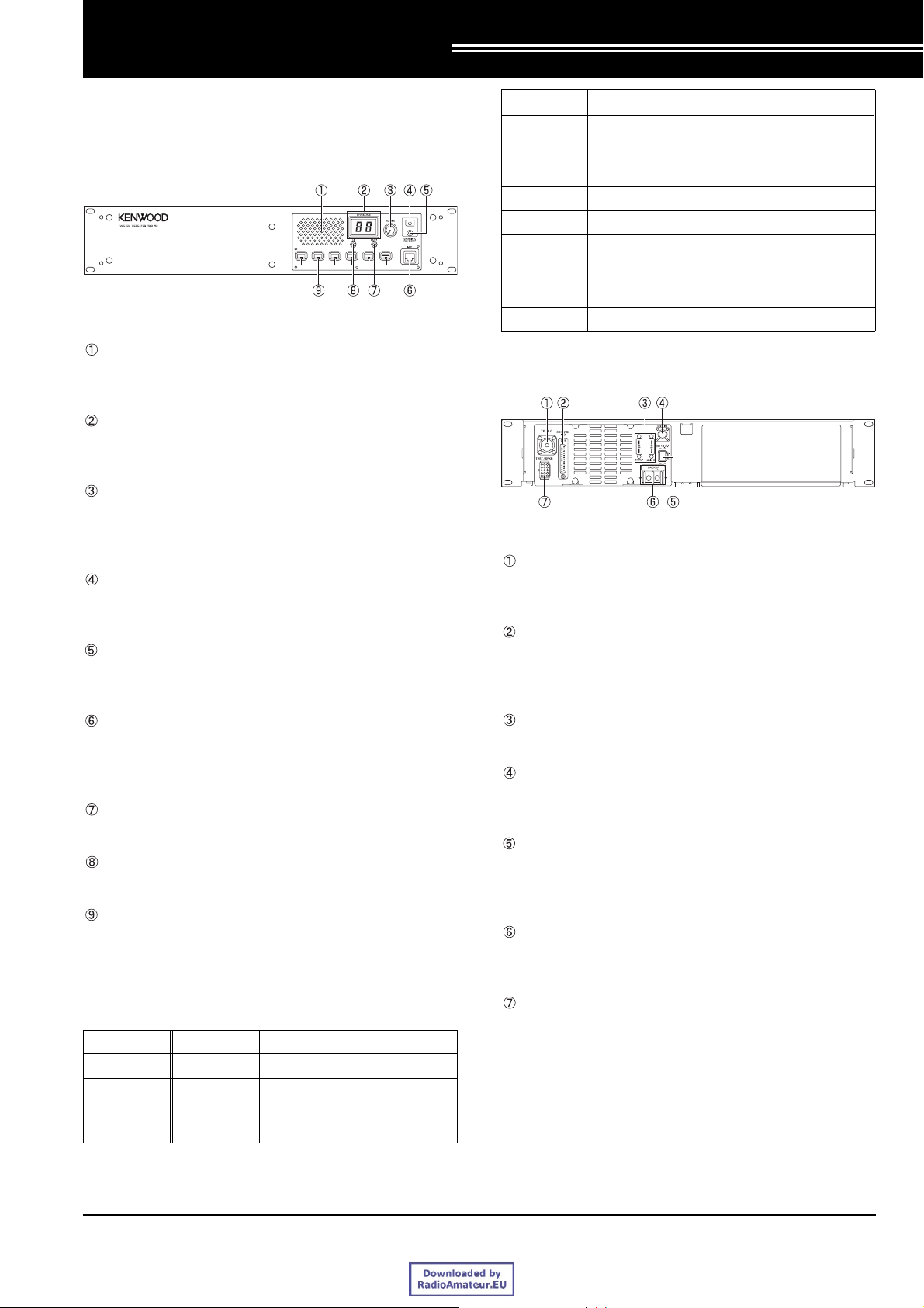
! Front Panel
Figure 1-1 Front Panel
Speaker
The speaker emits the received audio signals and
alert tones.
Channel/Status display
Two 7-segment LEDs can display channel numbers,
name and the status.
Volume Knob
The volume increases while turning the volume knob
clockwise and decreases while turning it
counterclockwise.
Power switch
Press this switch to turn ON and press it again to turn
OFF.
POWER LED
The LED lights green while using with main power
(DC) or lights red while using with the backup power.
Pin number Pin name Description
PTT signal input./
4PTT/TXD1
5MIG 6MIC -
7HOOK/RXD1
8 NC No connection
PC serial data from TKR-750/
850/751/851. PC read, PC
tuning, Firmware programming
HOOK signal input. /
PC serial data to TKR-750/850/
751/851. PC write, PC tuning,
Firmware programming
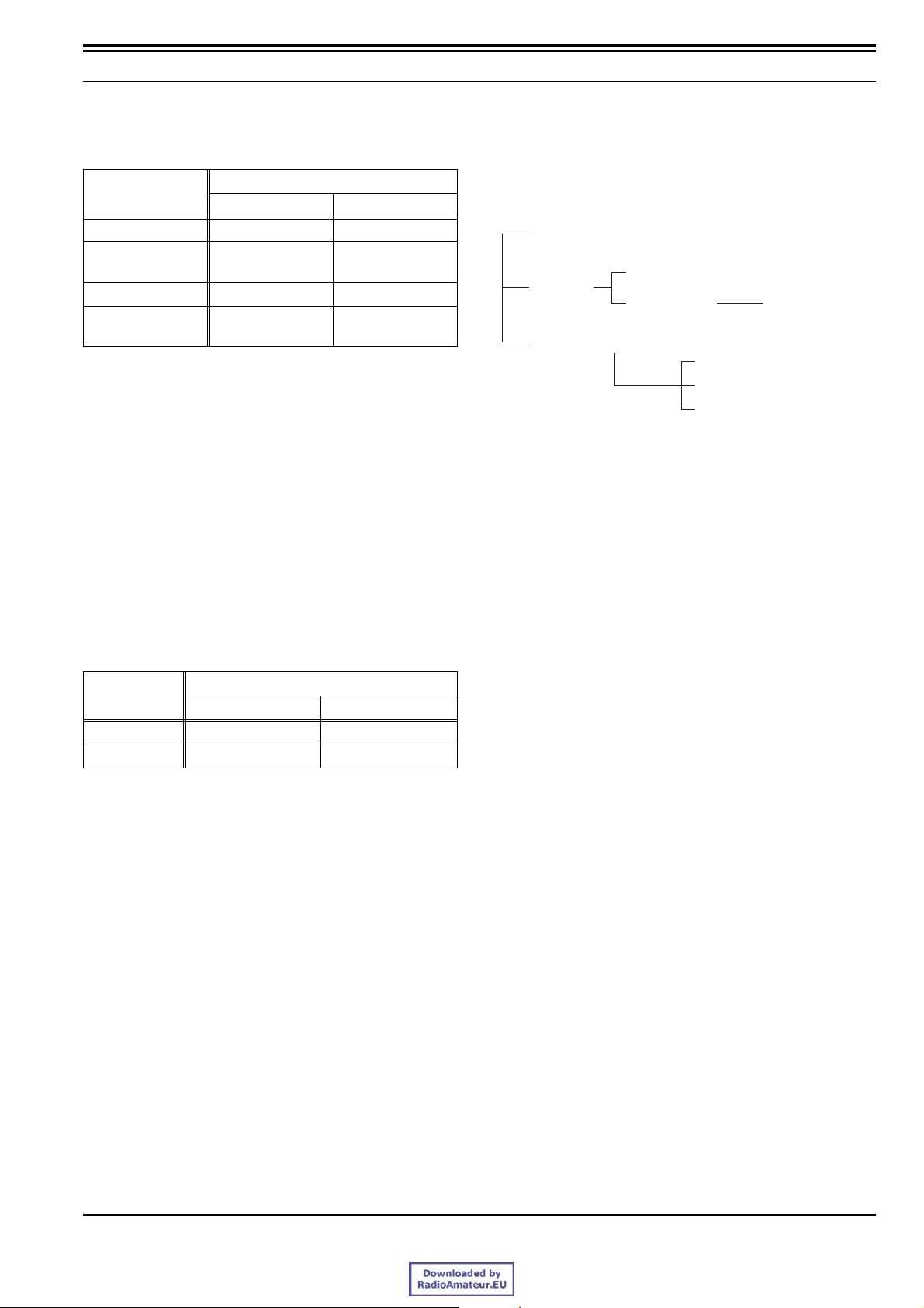
! Rear Panel
Figure 1-2 Rear panel
Antenna jack for transmission
This jack allows you to connect the transmission
antenna, duplexer or RF amplifier.
Control Interface jack (25-pin connector)
This jack allows you to connect an external device or
controller. (Refer to Table 1-2 Assigning signals to 25-
pin connector.)
Microphone connector (8-pin connector)
You can connect a microphone with this connector.
(Refer to Table 1-1 Assigning signals to the 8-pin
connector.)
BUSY LED
This LED lights green while receiving signal.
TX LED
This LED lights red while transmitting.
PF key (Programmable Function key)
Press a PF (Programmable Function) key to activate
the assigned function. A key LED lights orange while
the assigned function is activated.
Tabl e 1-1 Assigning signals to the 8-pin connector
Pin number Pin name Description
1 NC No connection
2SB
3 GND Ground
Switched + B output:
10.8 - 15.6 V/ 0.2 A max.
Fuse
You can attach a 10 A fuse.
Antenna jack for reception
This jack allows you to connect the reception antenna,
duplexer or Pre-selector.
Power connector
This connector allows you to connect a power cable.
With this code, DC 13.6 V (K-type) power are supplied
into TKR-750/850/751/851.
Backup Battery terminal
This terminal allows you to connect the backup
battery.
TEST/SPKR jack (15-pin connector)
This jack allows you to connect an external speaker.
You can use this jack for making input/output tests.
Also some signals arrive on these connector. (Refer
to Table 1-3 Assigning signals to the 15-pin
connector.)
Version: 1.01 USA Function Reference (FUNC) 1

1 BASIC OPERATION
Table 1-2 Assigning signals to 25-pin connector
Pin
number
Pin
number
Pin name Input/output Description
1 NC --- No connection
2 RXD2 Input
3TXD2Output
4 AUXI 1 Input CMOS Input
5 AUXI 2 Input CMOS Input
6 AUXI 3 Input CMOS Input
7DG --- Digital GND
8 TD Input Transmitted data input
9 TA Input
10 RD Output
11 RA Output
12 RXG --- RX GND
13 SPM Input
14 NC --- No connection
EXT.
15
MON
16 EXT. PTT Input
17 SC Output
18 NC --- No connection
19 TXG --- TX GND
20 AUXIO 1 Input/output CMOS Input/Output
21 AUXIO 2 Input/output CMOS Input/Output
22 AUXIO 3 Input/output CMOS Input/Output
23 AUXIO 4 Input/output CMOS Input/Output
24 AUXIO 5 Input/output CMOS Input/Output
25 AUXIO 6 Input/output CMOS Input/Output
Table 1-3 Assigning signals to the 15-pin connector
Pin name Input/output Description
1SB Output
2SB Output
3 NC --- No connection
4 GND --- Ground
Input
PC serial data input
RS-232C Level/Polarity
PC serial data output
RS-232C Level/Polarity
Transmitted audio signa l
input
Received Detect signal
output
Received audio signal
output
Speaker Mute input
Mute “L”
External Monitor Switch
input
Monitor “L”
External PTT Switch
input
PTT ON “L”
Squelch Control output
BUSY “L”
Output voltage
10.8 - 15.6 V:
1 A maximum
Output voltage
10.8 - 15.6 V:
1 A maximum
Pin
number
Note: Refer to the “Modification Information” for the detailed
Pin name Input/output Description
5 GND --- Ground
6 SPG --- Speaker ground
7 RD Output Received Detect output
8 RSSI Output RSSI signal output
9 SPI Input Internal Speaker input
Auxiliary
10
output 1
Auxiliary
11
output 2
12 SPO Output
Auxiliary
13
output 3
Auxiliary
14
output 4
Auxiliary
15
output 5
information.
Output Open collector
Output Open collector
External Speaker output
(4 W/ 4Ω)
Output CMOS Output
Output CMOS output
Output CMOS output
1.2 TX/RX Frequency
This is a frequency pair used for transmitting and
receiving. The value differs corresponding to the area,
where a repeater is used.
Table 1-4 Transmission/Reception Frequency, Step
Model Type
TKR-751 K 146 - 174 2.5/ 5/ 6.25
TKR-851
K 450 - 480 5/ 6.25
K2 480 - 512 5/ 6.25
You can program a transmission frequency and a
reception frequency of TKR-750/850/751/851 to each
channel.
! Configuration of KPG-91D
" Configuring a transmission frequency and a
reception frequency to a channel
(Refer to FPRG 6.2.1 Reception Frequency and
6.2.2 Transmission Frequency.)
Transmission/Reception Frequency
Range [MHz] Step [kHz]
2 Function Reference (FUNC) Version: 1.01 USA
1 BASIC OPERATION
1.3 Transmit output power
Table 1-5 Transmission Outp ut Power: Low/High
Model
TKR-750 Version 1 25 50
TKR-750 Version 2
TKR-850 Version 1 25 40
TKR-850 Version 2
Transmission Output Power [W]
Low High
25
(Adjustable to 15W)
25
Adjustable to 15W)
50
40
! Configuration of KPG-91D
" Configuring the transmission output power (low or
high) to a channel (Refer to 4.10 TX High Power.)
1.4 Bandwidth
Frequency bandwidth is a width of frequency used for
making a transmission. It has to select a bandwidth
approved. The value differs corresponding to the area,
where a repeater is used.
Table 1-6 Bandwidth: Wide/ Narrow
Model
TKR-750(VHF) 30, 25 15, 12.5
TKR-850(UHF) 25 12.5
! Configuration of KPG-91D
" Configuring the transmission bandwidth to a
channel (Refer to 4.6 Wide/ Narrow.)
Transmission Bandwidth [kHz]
Wide Narrow
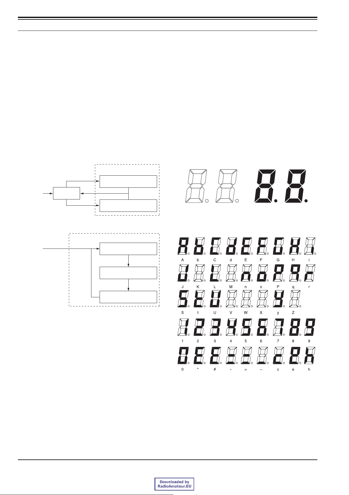
1.5 Mode
Following are modes operating and transition to each
mode:
" Mode
User Mode
PC Programming Mode
PC Mode
PC Test Mode PC Tuning Mode
Firmware Programming Mode
115200 bps Mode (DG-binary)
57600 bps Mode (DG-binary)
38400 bps Mode (DG-binary)
• User Mode
This mode allows you to operate the TKR-750/850/
751/851 as a base station or repeater. The TKR-750/
850/751/851 automatically starts up under User Mode
when turning it ON while data is correctly configured.
In this case, you do not have to press any keys. You
can configure a base station function or repeater
function on each channel. (Refer to 4 Channel
Information.)
With this mode, DSP program in a internal flash
memory is written to the DSP RAM when turning it
ON. When it is controlling remotely, high/low signal is
entered from an external device via an auxiliary input
terminal, then various functions are activated. (Refer
to 20 Function Port.)
This mode supports DTMF Air Remote function.
(Refer to 17 DTMF, 18 Remote Control.)
• PC Mode (Refer to 24 PC Mode.)
PC Mode is a mode activated after starting up under
the User Mode and this mode is controlled with
commands entered through a PC. Data
communication is made through the microphone
connector (8-pin connector) located on the front
panel or the control interface jack (25-pin connector),
which is in conformity with the RS-232C standard
located on the rear panel. The baud rate of data
communication is 9600 bps. (Refer to Table 1-2
Assigning signals to 25-pin connector.)
• PC Programming Mode (Refer to 24.1 PC
Programming Mode.)
This Mode is activated by the PROGRAM command
sent from a computer and allows you to read or write a
configuration data between FPU and TKR-750/850/
751/851.
Version: 1.01 USA Function Reference (FUNC) 3
1 BASIC OPERATION
• PC Test Mode (Refer to 24.2 PC Test Mode.)
The PC Test Mode is a mode to activate by the
TUNING command sent from a computer, and in this
mode, you can control transmission and reception by
the computer.
• PC Tuning Mode (Refer to 24.2.3 PC Tuning Mode.)
This mode allows you to adjust various transmission
and reception adjustment under the PC Test Mode.
• Firmware Programming Mode (Refer to 25 Program.)
You can program a firmware update in this mode. You
are able to program the firmware using a special
software (FPRO.EXE) and a programming speed is
115200 bps, 57600 bps, or 38400 bps. The DSP
software is also written into a flash memory.
" Transition to each mode
PC Mode
Power ON
Command
User Mode
Command
PC Programming Mode
Command "E"
PC Test Mode
1.6 Display
Following are display functions of the front panel:
" LED
• 7-segment LED: 2 digits
•TX LED: red
• BUSY LED: green
• POWER LED: green and red
• PF1 to PF6 keys LED
1.6.1 7-segment LED
Alpha-numeric characters are displayed by switching On
and Off 7 bars.
All segments unlit All segments lit
PC Firmware Programming Mode
Power ON
+
PF1 key
PF1 key
Note: The Firmware Programming setting must be enabled by
FPU before entering into PC Firmware Programming Mode.
(Refer to 14 Firmware Programming Mode Setting.)
115200 bps Mode "P.G."
PF1 key
57600 bps Mode "P.G."
PF1 key
38400 bps Mode "P.G."
Figure 1-3 All 7-segment LEDs while lit and un-lit.
Figure 1-4 Available characters
Note:
# Although you can use “A” to “_”, you cannot use the upper “C”
since it is used in the scanning display and the Programming
Mode display.
# In addition, you cannot use “K”, “M”, “V”, “W”, “X”, and “Z”.
4 Function Reference (FUNC) Version: 1.01 USA

1 BASIC OPERATION
Table 1-7 Example of LED display
Repeater status
Non-Priority
Channel (ADD)
Non-Priority
Channel (DEL)
Priority Channel .1
PC Programming
Mode
PC Test Mode
PC Tuning Mode
Firmware
Programming
Mode
Un-Programmed E1
Channel data
blank
PLL Un-Lock E3
TX frequency
data blank
Scanning Mode SC “SC” appear automatically.
LED
display
16.
16 -
PC
P.G.
PG.
PG
E2
E4
Description
DOT (.) appears on the right
side of the right digit.
DOT (.) appears on the right
side of the left digit.
“PC” appears automatically
after receiving PC command.
DOTs (.) appear on the right
side of left and right digit s for
115200 bps data speed.
DOT (.) appears on the right
side of the right digit for
57600 bps data speed.
No DOT for 38400 bps data
speed.
This character appears when
all channels are blank.
This character appears when
the selected channel is
blank.
(In case of a blank channel is
selected in remote controller,
etc.)
TX PLL Un-Lock: TX LED
blinking.
RX PLL Un-Lock: BUSY LED
blinking.
This character appears when
attempting to transmit with a
channel which does not be
assigned a transmission
frequency.
(Val id for Repeater PTT, local
microphone PTT, external
PTT)
! Configuration of KPG-91D
" Configuring the function for switching On/Off the
display (Refer to FPRG 6.5 “Key Assignment”
window, 6.9 “Remote Control” window, and 6.10
“Function Port” window.)
1.6.3 BUSY LED
Following are the conditions for the BUSY LED to light
green:
• TKR-750/850/751/851 is receiving a signal.
• TKR-750/850/751/851 reads data by KPG-91D.
You can assign the function for switching the display On/
Off function to an auxiliary port and PF key. (Refer to 15
Key Assignment, 18 Remote Control, 20 Function Port.)
! Configuration of KPG-91D
" Configuring the function for switching On/Off the
display (Refer to FPRG 6.5 “Key Assignment”
window, 6.9 “Remote Control” window, and 6.10
“Function Port” window.)
1.6.4 POWER LED
The LED lights green while TKR-750/850/751/851 is
using a main power and the LED lights red while using a
backup power.
Note: You must connect backup battery terminal with a backup
battery to use the backup power.
1.6.5 PF1 to PF6 keys LED
When functions are assigned to PF1 to PF6 keys and
pressed, the LED lights and the assigned function is
activated.
You can assign switching the display On/Off function to
auxiliary ports and PF keys. (Refer to 15 Key Assignment,
18 Remote Control, 20 Function Port.)
1.6.2 TX LED
! Configuration of KPG-91D
" Configuring the function for switching On/Off the
Following are the conditions for the TX LED to light red:
• TKR-750/850/751/851 is transmitting.
display (Refer to FPRG 6.5 "Key Assignment"
window, 6.9 "Remote Control" window, and 6.10
"Function Port" window.)
• TKR-750/850/751/851 is sending data to PC during
FPU reading.
Y ou can assign a function for switching the display On/Off
function to an auxiliary port and PF key. (Refer to 15 Key
Assignment, 18 Remote Control, 20 Function Port.)
Version: 1.01 USA Function Reference (FUNC) 5
1 BASIC OPERATION
1.7 Operation
1.7.1 Turning ON/OFF
Press the Power switch to turn TKR-750/850/751/851
ON. Press the switch again to turn it OFF.
When TKR-750/850/751/851 is turned ON, the PF keys,
TX LED, BUSY LED, and Channel/Status display light for
one second, then the status appears on the Channel/
Status display. (Refer to 1.6 Display.)
The POWER LED lights green when TKR-750/850/751/
851 is using a main power (DC) or lights red while using
backup power.
1.7.2 Adjusting Volume Level
Turn the VOLUME knob clockwise to increase the audio
level from the speaker and decreases by turning it
counterclockwise.
Note: You cannot change the beep volume by the VOLUME knob
since it is configured by FPU. (Refer to 9 Tone.)
1.7.3 PF keys
Press a PF key to activate a function assigned on each
key. A key LED light s orange while the assigned function
is activating. (Refer to 15 Key Assignment.)
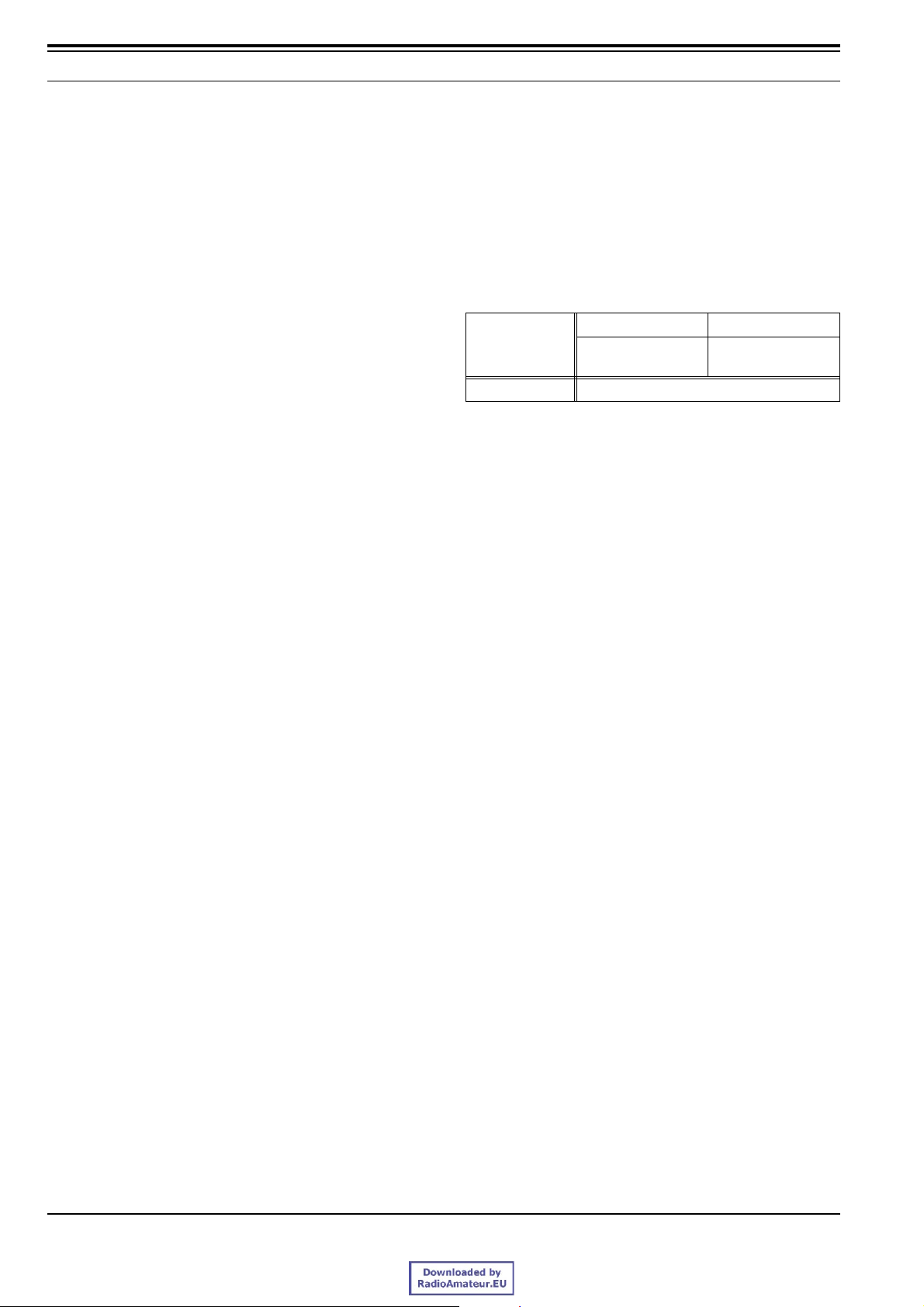
1.8 Squelch Level
Squelch is a function that eliminate noise occurring when
there is no signal to receive. With this function, TKR-750/
850/751/851 automatically eliminates the noise and it
opens squelch during receiving a call in order to listen to
the received audio signals.
The squelch level is a open level of the squelch when
receiving signal is weak.
Table 1-8 Squelch level
01 - 15
Range
Step 1
You can configure the squelch level and assign On/Off
status to auxiliary ports and PF keys.
(Refer to 15 Key Assignment, 20 Function Port.)
The configured squelch level is used as the starting level
of the repeat operation.
! Configuration of KPG-91D
" Configuring the squelch level (Refer to FPRG
6.4.1 "Optional Features 1" tab.)
" Assign the function for switching On/Off. (Refer to
FPRG 6.5 "Key Assignment" window, 6.10
"Function Port" window.)
Mute function is
completely disabled.
Shallow - Tight
6 Function Reference (FUNC) Version: 1.01 USA

2 PASSWORD
TKR-750/850/751/851 has a function for setting a
password to prevent the configuration data.
2.1 Data Password
The data password function prevents a configuration data
from being read by unauthorized persons. With this
function, the configuration data of TKR-750/850/751/851
will not be read even when it is stolen.
You can configure the password by FPU (up to 6
characters).
When the password is set to TKR-750/850/751/851, it is
impossible to read its configuration data by KPG-91D
unless you enter the correct password. If you lost the
password, call our Technical Support or Service center.
Note: Data Password prevents from reading the configured data,
and this does not prevent from writing the configured data.
! Configuration on the KPG-91D
" Configuring the function for setting a password to
the configuration data of TKR-750/850/751/851.
(Refer to FPRG 6.4.1 “Optional Features 1" tab.)
Version: 1.01 USA Function Reference (FUNC) 7

3 EMBEDDED MESSAGE
The TKR-750/850/751/851 has the function to embed a
message.
3.1 Embedded Message
This function allows you to store a message with up to 64
alphanumeric characters (combination of alphabets and
numerals) into TKR-750/850/751/851.
You can embed the specific information, such as the
control number and the name of the configuration data
You can write/ read messages into/ from TKR-750/850/
751/851 by FPU. The message is stored as a part of the
configuration data.
! Configuration of KPG-91D
" Configuring a message to be embedded in TKR-
750/850/751/851 (Refer to FPRG 6.14 “Embedded
Message” window.)
" Writing the configuration data to TKR-750/850/751/
851 (Refer to FPRG 7.2 Write Data to TKR-750/
850/751/851.)
" Reading the configuration data from TKR-750/850/
751/851 (Refer to FPRG 7.1 Read Data from TKR750/850/751/851.)
3.2 Embedded Message w/
Password
Embedded Message w/Password is a function for storing
a message with up to 64 alphanumeric and protecting it
with a password.
You can embed the specific information of TKR-750/850/
751/851, such as the control number and the name of the
configuration data with a password.
You are able to write the message and password into
TKR-750/850/751/851 by FPU.
By writing the Embedded Message w/Password, you can
store the message as a separate data from the
configuration data instead of as a part of the configuration
data, which differs from writing the Embedded message.
You must enter the correct password to write a message.
You are not allowed to embed the message unless you
enter correct password.
You can read the messages embedded into TKR-750/
850/751/851.
! Configuration on the KPG-91D
" Writing a message with password to TKR-750/850/
751/851 (Refer to FPRG 7.2 Write Data to TKR750/850/751/851.)
" Reading the configuration data from TKR-750/850/
751/851 (Refer to FPRG 7.1 Read Data from TKR750/850/751/851.)
8 Function Reference (FUNC) Version: 1.01 USA

4 CHANNEL INFORMATION
A pair of transmission and reception frequencies is called
as channel for making a communication. You can
configure maximum 16 channels in order to transmit and
receive.
You can configure following functions by KPG-91D.
RXFrequency
TX Frequency
QT/DQT Decode
QT/DQT Encode
Channel Name
Wide/ Narrow
Encode Tone in Multiple
Operation Mode
Multi Table
Beat Shift
TX High Power
QT Reverse Burst
Scan Add
Compander
CW ID
Scrambler
! Configuration of KPG-91D
" Configuring a channel (Refer to FPRG 6.1
“Channel Information” window.)
4.2 Transmission Frequency
This is a frequency used for transmitting.
You can specify your desired transmitting frequency
within the range. (Refer to 1.2 TX/RX Frequency.)
! Configuration of KPG-91D
" Configuring the Transmission Frequency (Refer to
FPRG 6.2.2 Transmission Frequency.)
4.3 QT/DQT Decode
QT/DQT Decode is a function to wait for a specific call.
QT/DQT Decode facilitates communication within the
specified group when the same channel is sharing with
other groups. It will effects to exclude the other group
communication with muting. With this function, you can
communicate without listening to conversations of other
groups.
It is possible to configure the QT/DQT Decode code on
each channel by FPU.
TKR-750/850/751/851 unmutes audio when the received
QT/DQT matched and a received audio is transmitted
under repeat operating.
TKR-750/850/751/851 does not unmute when the
received QT/DQT does not matched and a received
audio is not transmitted if it is operating as Repeater.
You can use the QT/DQT Decode function of the Multi
Table at the same time in order to wait for a call. (Refer to
4.7 Encode Tone in Multiple, 21 Multi-table.)
! Configuration of KPG-91D
4.1 Reception Frequency
This is a frequency used for reception.
You can specify your desired receiving frequency within
the range. (Refer to 1.2 TX/RX Frequency.)
! Configuration of KPG-91D
" Configuring the Reception Frequency (Refer to
FPRG 6.2.1 Reception Frequency.)
Version: 1.01 USA Function Reference (FUNC) 9
" Configuring the QT/DQT Decode (Refer to FPRG
6.2.3 QT/DQT Decode.)
4.4 QT/DQT Encode
QT/DQT Encode is a function to make a Group call.
Encoding QT/DQT limits communication within the
specified group when the same channel is sharing with
other groups. Signals from other groups are muted. With
this function, you can communicate without listening to
conversations of other groups.
It is possible to configure the QT/DQT Encode code on
the each channel by FPU.
The configured QT/DQT Encode code is transmitted
while transmitting with audio continuously.
Note:

4 CHANNEL INFORMATION
# When QT Encode and the QT Reverse Burst function are
enabled, TKR-750/850/751/851 transmits the QT Reverse Burst
code at end of transmission.
# When the DQT Encode is selected, TKR-750/850/751/851
transmits the QT Turn-off Code at end of transmission.
! Configuration of KPG-91D
" Configuring the QT/DQT Encode (Refer to FPRG
6.2.4 QT/DQT Encode.)
4.5 Channel Name
You can assign 2 digit characters to each channel name.
The configured channel name appears on the Channel/
Status display. (Refer to 1.6 Display.)
! Configuration of KPG-91D
" Configuring a Channel Name (Refer to FPRG
6.2.5 Channel Name.)
transmit. (The operation of repeat PTT switch is
excluded.)
The encode operation varies depending on the PTT type.
4.6 Wide/ Narrow
You can choice a transmission bandwidth. The value
depends on the area or your license. (Refer to 1.4
Bandwidth.)
! Configuration of KPG-91D
" Configuring the frequency bandwidth (Refer to
FPRG 6.2.6 Wide/ Narrow.)
4.7 Encode Tone in Multiple
This function allows you to wait calls with maximum 16
different QT/DQT codes by setting additional 15 QT/DQT
(Current) as well as the QT/DQT code (Primary) set on a
each channel. You can set a Main code and a Sub code
in a Multi table. (Refer to 21 Multi-table.)
TKR-750/850/751/851 encodes QT/DQT Encode code
matching QT/DQT Decode in primary and current QT/
DQT codes while it operates under Repeat Mode or
Duplex Mode.
Note: You cannot use Multi Table while the TKR-750/850/751/851
operates under Simplex Mode. (Refer to 4.8 Operation
Mode.)
If TKR-750/850/751/851 receives a transmission request
from Local Mic PTT or external PTT except Simplex
Mode, it automatically selects the signalling code to
10 Function Reference (FUNC) Version: 1.01 USA

Tabl e 4-1 Primary: TKR-750/850/751/851 transmits with a
configured signalling on each cha nnel.
Status PTT Priority Operation Description
Repeater PTT <
Local Mic PTT,
A channel becomes
free or a signalling of
Multi-table is
unmatched.
TKR-750/850/751/851
makes a repeat
operation since a
signalling on Multitable is matched.
External PTT
Repeater PTT >
Local Mic PTT,
External PTT
Repeater PTT <
Local Mic PTT,
External PTT
Repeater PTT >
Local Mic PTT,
External PTT
Local Mic PTT /
External PTT is
On
4 CHANNEL INFORMATION
TKR-750/850/751/851 transmits a Primary signalling code configured on
each channel. It keeps to transmit the Primary code even if it receives a
signalling code of Multi-table during transmitting. When Local Mic PTT or
External PTT is released, It starts repeat operation with a Current signalling
code of Multi-table after transmitting a QT Reverse Burst or DQT Turn-off
Code of Primary code.
TKR-750/850/751/851 transmits a Primary signalling code configured on
each channel. It starts repeat o perat io n wi th a Curre nt s ign all in g code wh en
it receives a signalling of Multi-table during transmitting. When the recei vin g
signalling code of Multi-table i s unmatched, It st arts to tra nsmit Primary code
after transmitting a QT Reverse Burst or DQT Turn-off Code of Current
signalling code.
TKR-750/850/751/851 transmits a Priority signalling code configured on
each channel. When Local Mic PTT or External PTT is released while it is
receiving a Current signalling code, it starts repeat operation with the
Current signalling code of the Multi-table after transmitting a QT Reverse
Burst or DQT Turn-off Code of Primary signall ing code.
TKR-750/850/751/851 keeps repeat o peration with a Current signalling code
of Multi-table. When Local Mic PTT or External PTT keeps On and a
signalling of Multi-table is unmatched, I t transmits a Primary signalling code
configured on a channel after transmi tti ng a QT Reve rse Burst or DQT Turnoff Code of Current signalling code.
Tabl e 4-2 Current: TKR-750/850/751/851 transmits with a
encode signalling in order to match a Current decoded
signalling code.
Status PTT Priority Operation Description
Repeater PTT <
Local Mic PTT,
A channel becomes
free or a signalling of
Multi-table is
unmatched.
TKR-750/850/751/851
makes the repeat
operation since a
signalling of Multitable is matched.
External PTT
Repeater PTT >
Local Mic PTT,
External PTT
Repeater PTT <
Local Mic PTT,
External PTT
Repeater PTT >
Local Mic PTT,
External PTT
Local Mic PTT/
External PTT is
On
TKR-750/850/751/851 transmits a Primary signalling code configured on
each channel. It keeps to transmit the Primary code even if it receives a
signalling of the Multi-table during transmitting. When Local Mic PTT or
external PTT is released, It starts repeat operation with a Current signalling
code of Multi-table after transmitting a QT Reverse Burst or DQT Turn-off
Code of Primary signalling code.
TKR-750/850/751/851 transmits a Primary signalling code configured on
each channel. It starts repeat o perat io n wi th a Curre nt s ign all in g code wh en
a signalling of Multi-table is matched during transmitting. When the
signalling of Multi-table is unmatched, I t starts to transmit a Primary code
after transmitting a QT Reverse Burst or DQT Turn-off Code of Current
signalling code.
TKR-750/850/751/851 keep to transmit with the Current signalling code on
the Multi-table. When Local Mic PTT or External PTT is On and a signalling
of Multi-table is unmatched, it st arts to transmit a Primary signalling code of
Multi-table after transmitting a QT Reverse Burst or DQT T urn-off Code of
Current signalling code.
TKR-750/850/751/851 keep to transmit a Current signalling code of Multitable.
When Local Mic PTT or External PTT is On and a signalling of Multi-table is
unmatched, it starts to transmit a Primary signalling cod e of Mul ti- t ab le after
transmitting a QT Reverse Burst or DQT Turn-off Code of Current signalling
code.
! Configuration of KPG-91D
" Configuring the Encode Tone in Multiple (Refer to
" Configuring the Multi Table (Refer to FPRG 6.2.9
Multi Table (Channel Edit).)
FPRG 6.2.7 Encode Tone in Multiple.)
" Configuring Operation Mode (Refer to FPRG 6.2.8
Operation Mode.)
Version: 1.01 USA Function Reference (FUNC) 11

4 CHANNEL INFORMATION
4.8 Operation Mode
You can configure Repeat, Simplex or Duplex mode to
each channel.
Select Repeat Mode for repeat operation channel.
Select Duplex Mode for two-way simultaneous
communication channel (using different frequencies for
transmission and reception).
Select Simplex Mode for one-way communication
channel (using a same frequency for transmission and
reception).
Table 4-3 Operation Mode Function
Mode Description
TKR-750/850/751/851 starts a repeat operation
when QT/DQT code is matched and transmits using
Repeat
Simplex
Duplex
the transmission frequency and a QT/DQT Encode
code. When it is operating under this mode, a
received audio is modulated and you can monitor
the audio.
This communication method is referred to as
“Simplex system” since same frequency, which is
for RX and TX is used for each other. On a channel
configured this Mode, it is impossible to receive a
call while transmitting. A received audio is muted
when the Local Mic PTT or the External PTT is on.
This communication method is referred to as
“Duplex system” since different frequencies, which
is for RX and TX are used. On the channel
configured this Mode, it is possible to receive a call
even while transmitting. TKR-750/850/751/851
transmits without muting the recei ved audio when
the Local Mic PTT or the External PTT is on.
4.9 Beat Shift
This function eliminates a problem of receiver's internal
interference caused by internal oscillators.
The harmonic of oscillator implemented for the
microprocessor may interfere with receiving audio. You
can eliminate this problem by slightly shifting a frequency
of oscillator used for the microprocessor.
Each channel can be assigned as enable or disable this
function separately by KPG-91D.
! Configuration of KPG-91D
" Enabling/disabling the Beat Shift function in each
channel (Refer to FPRG 6.2.10 Beat Shift.)
4.10 TX High Power
You can select a transmission output power (high or low)
on each channel.
! Configuration of KPG-91D
" Configuring the transmission output power (high or
low) to each channel (Refer to FPRG 6.2.11 TX
High Power.)
Note: Scan does not work on the Repeat channel. That channel is
limited for repeat operation only. (Refer to 4.12 Scan Add.)
! Configuration of KPG-91D
" Configuring Operation Mode (Refer to FPRG 6.2.8
Operation Mode.)
4.11 QT Reverse Burst
This function eliminates a squelch tail noise of the end of
communication. TKR-750/850/751/851 transmits a QT
Reverse Burst code immediately at end of transmitting.
(Refer to 5 QT/DQT.)
You can configure a QT Reverse Burst using KPG-91D
! Configuration of KPG-91D
" Configuring the QT Reverse Burst (Refer to FPRG
6.2.12 QT/DQT Reverse Burst.)
Note: A DQT Turn-off code is always transmitted even if a QT
Reverse Burst is configured as disabled.
(Refer to 5.2 DQT Turn-off Code.)
12 Function Reference (FUNC) Version: 1.01 USA

4 CHANNEL INFORMATION
4.12 Scan Add
This function is to check a signal on each channel.
TKR-750/850/751/851 scans an available signal to
receive and when it finds an available signal, scanning is
paused.
Y ou can configure the scan operation and select channels
to be scanned. (Refer to 16 Scan.)
You can also configure the function for activating/
deactivating scan to an auxiliary port and PF keys.
! Configuration of KPG-91D
" Selecting a channel to be scanned (Refer to FPRG
6.2.13 Scan Add.)
" Configuring the scan operation (Refer to FPRG 6.6
“Scan Information” window.)
Note: It is impossible to assign a scan function on a channel
configured Repeat Mode since it is only used for repeat
operation. (Refer to 4.8 Operation Mode.)
code selection ports are available inside of TKR-750/850/
751/851 for a Scrambler code selection.
(Refer to 4.14.1 Scrambler Code.)
! Configuration of KPG-91D
" Enabling/disabling the Compander function on
each channel (Refer to FPRG 6.2.17 Voice
Scrambler.)
Note:
# The repeat audio under the Repeat Mode is not scrambled even
if the Voice Scrambler function is enabled.
# When the function for switching Scrambler On/Off is assigned to
the PF key, the key top LED lights when the Voice Scra mbler
function is On.
4.14.1 Scrambler Code
The Voice Scrambler function is switched On when TKR750/850/751/851 is ON or a channel is changed. The
code selection ports are available inside of TKR-750/850/
751/851 to select a Scrambler code.
It is possible to select a Scrambler code on each channel.
4.13 Compander
This function is a function to improve quality of the
received audio by reducing noise while transmitting.
A compressor effects on the Local microphone input
signal and TA input signal, and a expander effects on a
speaker audio and RA audio.
It is possible to assign Compander function enable or
disable on each channel separately.
! Configuration of KPG-91D
" Enabling/disabling the Compander function for
each channel (Refer to FPRG 6.2.14 Compander.)
Note: The Compander function does not operate on the audio
signal to be repeated.
4.14 Voice Scrambler
Voice Scrambler is a function to keep a conversation
private within a group. With this function, a
communication is made using a special signal in order to
prevent communications from being monitored by
unauthorized people intercepting communications. You
can use this function only when a optional voice scramble
board is installed into the TKR-750/850/751/851. (Refer
to: FPRG 5.1 “Model Information” window.)
The Voice Scrambler function can be turned On when
TKR-750/850/751/851 is ON or changing a channel. The
Table 4-4 Scrambler Code
Scrambler
Code
1LLLL
2LLLH
3LLHL
4LLHH
5LHLL
6LHLH
7LHHL
8LHHH
9HLLL
10 H L L H
11HLHL
12 H L H H
13 H H L L
14 H H L H
15 H H H L
16HHHH
CODE4 CODE3 CODE2 CODE1
Code selection port
! Configuration of KPG-91D
" Configuring the Scrambler code to each channel
(Refer to FPRG 6.2.18 Scrambler Code.)
Note: The code selection port in TKR-750/850/751/851/751/851
selects a Scrambler code when TKR-750/850/751/851/751/
851 is ON a channel is changed even if the Voice Scrambler
function is off.
Version: 1.01 USA Function Reference (FUNC) 13

4 CHANNEL INFORMATION
4.14.2 Scrambler Backup
This function restores a Voice Scrambler configuration.
With this function, the configuration is not cleared even if
TKR-751/851 is turned OFF after configure Voice
Scrambler function. When this function is switched Off,
the configuration of the Voice Scrambler is cleared and
returns to the default values.
! Configuration of KPG-91D
" Configuring the Scrambler Backup function (Refer
to FPRG 6.4.1 “Optional Features 1" tab.)
Note:
# You can use this function only when the optional Voice
Scrambler Board is installed into the TKR-750/850/751/851.
# Refer to the Modification Manual when installing a optional Voice
Scrambler Board into the TKR-750/850/751/851.
4.15 CW ID
You can transmit a fixed message, such as Call sign by
Morse code. (Refer to 22 CW ID/CW Message.)
! Configuration of KPG-91D
" Configuring the CW ID to each channel (Refer to
FPRG 6.2.15 CW ID.)
14 Function Reference (FUNC) Version: 1.01 USA

5 QT/DQT
The TKR-750/850/751/851 supports the QT/DQT
signalling.
The QT/DQT allows you to ignore unwanted calls from
other persons who are using a same frequency. With the
QT/DQT signalling, you can hear calls from only specific
persons or group that have a same QT/DQT code.
(Refer to 4.3 QT/DQT Decode, 4.4 QT/DQT Encode.)
You can also receive and make a call by a QT/DQT
Decode code of Multi-table at the same time. (Refer to
21 Multi-table.)
5.1 QT/DQT
The QT (Quiet Talk) uses a sub-audible tone (67.0 - 254.1
[Hz]). The DQT (Digital Quiet Talk) uses a 3-digit octal
number (23-bit/word) (code: 000 - 777). The DQT signal
has polarity and can be configured as Normal or Inverse.
Note: QT/ DQT cannot be heard from the speaker since it uses a
sub-audible tone.
You can configure the QT/DQT Encode and Decode
codes for each channel. (Refer to 4.3 QT/DQT Decode,
4.4 QT/DQT Encode.)
This function allows you to wait for a call a maximum of
16 QT/DQT codes while configuring 15 QT/DQT codes
(Current) as well as the QT/DQT code (Primary) to each
channel. (Refer to 4.7 Encode Tone in Multiple.)
! Configuration of KPG-91D
" Configuring the QT/DQT Decode (Refer to FPRG
6.2.3 QT/DQT Decode.)
" Configuring the QT/DQT Encode (Refer to FPRG
6.2.4 QT/DQT Encode.)
" Configuring the Encode Tone in Multiple (Refer to
FPRG 6.2.7 Encode Tone in Multiple.)
" Configuring the duration for the DQT Turn-off Code
transmission (Refer to FPRG 6.4.1 "Optional
Features 1" tab.)
5.3 QT Reverse Burst
This function eliminates squelch tail noise when the
transmitting party ends the communications. TKR-750/
850/751/851 transmits the QT Reverse Burst code at the
end of communications. It mutes the output audio when it
receives the QT Reverse Burst.
When the QT/DQT Encode code configured to the
channel is QT, TKR-750/850/751/851 transmits the QT
Reverse Burst Code.
You can configure the duration for transmitting the QT
Reverse Burst code in conjunction with the DQT Decode
performance of receiver.
! Configuration of KPG-91D
" Configuring the duration for transmitting the QT
Reverse Burst Code (Refer to FPRG 6.4.1
"Optional Features 1" tab.)
5.4 QT Decode Delay
This function is a delay time to start detecting a QT/DQT
signalling , which is transmitted from the radio as a
normal QT signalling, as the QT Reverse Burst code.
Y ou must configure the duration between the time that the
received QT signalling unmatches and starts the QT
Decode operation in order to use this function.
! Configuration of KPG-91D
" Configuring the QT Decode Delay (Refer to FPRG
6.4.1 "Optional Features 1" tab.)
5.2 DQT Turn-off Code
This function eliminates squelch tail noise when the
transmitting party ends the communications. A DQT
Turn-off Code is transmitted at the end of
communications. TKR-750/850/751/851 mutes the
output audio when the Turn-off Code is received.
When the QT/DQT Encode configured to the channel is
DQT, TKR-750/850/751/851 transmits the Turn-off Code.
YYou can configure the duration for transmitting the DQT
Turn-off Code in conjunction with the DQT Decode
performance of receiver.
! Configuration on the KPG-91D
Version: 1.01 USA Function Reference (FUNC) 15

5 QT/DQT
5.5 Off-hook Decode
TKR-750/850/751/851 receives the QT/DQT signalling
and opens squelch (Signalling Squelch) regardless of the
position of the local microphone. It operates under the
signalling squelch mode when the microphone is in onhook position and it receives a carrier and opens squelch
(Carrier squelch) while the microphone is in off-hook
position if this function is disabled.
! Configuration on the KPG-91D
" Configuring the off-hook Decode (Refer to FPRG
6.4.1 "Optional Features 1" tab.)
Note: When this function is disabled and the local microphone is in
off-hook position, TKR-750/850/751/851 operates in the
carrier squelch mode to mute or unmute the speaker. TKR750/850/751/851 operates in the signalling squelch mode
when TKR-750/850/751/851 makes the repeat operation.
16 Function Reference (FUNC) Version: 1.01 USA
 Loading...