


Function Reference (FUNC)
For
Version: 1.02
Last Updated: July, 2005
Language: English
Type: K
© Kenwood Corporation

About Copyright
All copyrights and other intellectual property rights for this technical document and relevant in-depth manuals as well as
the software described in this technical document, relevant in-depth manuals, and help texts and manuals attached to the
software are owned by Kenwood Corporation.
A right to use the software described in this technical document and relevant in-depth manuals is granted to a licensee by
Kenwood Corporation; however, the title to and ownership of the software shall be owned by Kenwood Corporation. Refer
to the help texts attached to this software for details.
Kenwood Corporation does not warrant quality and performance of the software described in this technical document and
relevant in-depth manuals to conform to the applicability of any use, and Kenwood Corporation shall be free from liability
for any defects, damage or loss, or from any warranty to anything other than expressly described in this technical
document and relevant in-depth manuals.

CONTENTS
1 OUTLINE .................................................... 1
1.1 Description of the TK-5210 ............................... 1
1.2 Features of the TK-5210 ................................... 1
1.3 Functions and Panel Layout.............................. 2
1.4 Description of Zone/ Channel............................ 4
1.5 Display (K2- or K3-type only) ............................ 5
1.6 Icons.................................................................. 5
1.7 Key Guide ......................................................... 6
1.8 Tone Pattern ..................................................... 7
1.8.1 Beep Tone....................................................... 7
1.8.2 Transpond Pattern........................................... 9
2 BASIC OPERATION.................................10
2.1 Turning the Transceiver ON/ OFF................... 10
2.1.1 Turning the Transceiver ON ......................... 10
2.1.2 Turning the Transceiver OFF ........................ 11
2.2 Selecting the Zone .......................................... 12
2.2.1 Selecting the Zone using the Selector........... 12
2.2.2 Selecting the Zone using the
Concentric Switch.......................................... 13
2.2.3 Selecting the Zone using the Lever Switch ... 13
2.2.4 Selecting the Zone using PF keys................. 13
2.2.5 Operations after Selecting a New Zone ........ 14
2.3 Selecting a Channel........................................ 14
2.3.1 Selecting the Channel using the Selector ..... 14
2.3.2 Selecting the Channel using PF keys............ 15
2.3.3 Operation after Selecting a New Channel..... 15
2.4 Home Channel ................................................ 15
2.5 Direct Channel ................................................ 16
2.6 Communication ............................................... 17
2.6.1 Receive ......................................................... 17
2.6.2 Transmission ................................................. 18
2.6.3 Transmitting with the Talk Around Function..... 18
2.7 Transmit Power ............................................... 18
2.7.1 Changing the Transmit Power....................... 18
2.8 Channel Spacing............................................. 19
2.9 Busy Channel Lockout .................................... 19
2.10 BCL Override .................................................. 20
2.11 Transceiver Password
(K2- or K3-type only)....................................... 20
2.12 Read Authorization Password......................... 22
2.13 Overwrite Password ........................................ 22
2.14 Beat Shift......................................................... 22
2.15 Compander ..................................................... 22
2.16 Key Lock ......................................................... 23
2.17 Keypad Operation (K3-type only).................... 24
2.18 Mic Sense Control........................................... 24
2.19 Battery Saver .................................................. 25
3 DISPLAY FUNCTION
(K2- AND K3-TYPE ONLY)...................... 26
3.1 Zone Name ..................................................... 26
3.2 Channel Name (Personality Name) ................ 26
3.3 Zone-name Text Length.................................. 27
3.4 Sub-LCD Display ............................................ 27
3.5 Display Character ........................................... 27
3.6 Power-on Text................................................. 28
3.7 Busy LED ........................................................ 28
3.8 Transmit LED .................................................. 28
3.9 Light ................................................................ 29
3.9.1 Using the Light Key ....................................... 29
3.9.2 Using the Auto Backlight functions ................ 29
3.10 Battery Status/ Warning .................................. 29
3.10.1 Battery Status................................................ 30
3.10.2 Battery Warning............................................. 30
4 SOUND FUNCTION ................................. 32
4.1 Minimum Volume ............................................ 32
4.2 Maximum Volume ........................................... 32
4.3 Tone Volume Offset ........................................ 32
4.4 Tone Volume................................................... 32
4.5 Alert Tone Pattern........................................... 33
4.6 Speaker Attenuation ....................................... 33
5 TALK AROUND FUNCTION .................... 34
6 TIME-OUT TIMER (TOT) FUNCTION ...... 35
6.1 TOT Pre-alert .................................................. 35
6.2 TOT Rekey Time............................................. 35
6.3 TOT Reset Time ............................................. 35
7 SIGNALING FUNCTION .......................... 36
7.1 QT/DQT Decode/ Encode............................... 36
7.2 Optional Signaling........................................... 36
7.3 Controlling Received Audio using Signaling
(Audio Control)................................................ 37
7.4 Conditions to Decode Optional Signaling
(Decode) ......................................................... 38
7.5 Monitor ............................................................ 38
7.6 Squelch Off (Analog Conventional)................. 39
7.7 Squelch Level ................................................. 40
FUNC (K)/Ver. 1.02 Confidential Index I

CONTENTS
8 DTMF FUNCTION.....................................41
8.1 Sending DTMF Tone .......................................41
8.1.1 Manual Dialing (K3-type only)........................41
8.1.2 Store & Send (K3-type only) .......................... 42
8.1.3 Autodial List Selection....................................43
8.1.4 Redial (K3-type only) .....................................44
8.1.5 Dial ID (K3-type only)..................................... 45
8.2 DTMF Encode Function...................................45
8.2.1 DTMF Sidetone .............................................. 45
8.2.2 DTMF Speed..................................................45
8.2.3 First Digit Time ............................................... 46
8.2.4 First Digit Delay Time.....................................46
8.2.5 * and # Digit Time ..........................................46
8.2.6 DTMF Hold Time............................................46
8.3 DTMF Decode Function...................................46
8.3.1 Code .............................................................. 46
8.3.2 Transpond/ Alert Tone ...................................47
8.3.3 Auto Reset Timer (DTMF)..............................47
8.3.4 Stun................................................................48
8.3.5 Clear to Transpond (DTMF)...........................48
8.3.6 Selective Call-alert LED (DTMF).................... 48
8.4 Autodial List .....................................................48
9 2-TONE FUNCTION..................................49
9.1 2-tone Decode Function ..................................49
9.1.1 Decoder 1 to 4 ...............................................49
9.1.2 A Tone, B Tone, C Tone, D Tone ..................50
9.1.3 Auto Reset Timer (2-tone) .............................50
9.1.4 Clear to Transpond (2-tone)...........................51
9.1.5 Selective Call-alert LED (2-tone) ...................51
10 PTT ID FUNCTION..................................52
10.1 PTT ID Type ..................................................52
10.2 Timing for Sending the PTT ID ......................52
10.3 Restricted ID in TA ........................................53
11 VOX (VOICE OPERATED
TRANSMISSION)....................................54
11.1 VOX Gain Level.............................................54
11.2 VOX Delay Time ............................................55
11.3 Transmit Inhibit while Receiving ....................55
11.4 Cancel Operation...........................................55
11.5 VOX Proceed Tone .......................................56
13 SCAN FUNCTION .................................. 59
13.1 Priority Scan ..................................................59
13.2 Revert Channel..............................................60
13.3 Dropout Delay Time.......................................61
13.4 Dwell Time.....................................................61
13.5 Lookback Time ..............................................61
13.6 AC Control .....................................................61
13.7 Priority Temporary Delete..............................62
13.8 Scan List........................................................62
13.9 Scan Sequence .............................................62
13.10 Channel Recall............................................63
13.11 Scan Delete.................................................63
13.12 Scan Program (K2- or K3-type only) ........... 64
13.12.1 The Transceiver Enters
Scan Program Mode. ....................................64
13.12.2 Editing the Scan List .....................................64
13.12.3 Changing the Priority Channel......................65
14 OST FUNCTION
(K2- AND K3-TYPE ONLY) .................... 66
14.1 OST Status Memory ......................................67
14.2 Tone Off.........................................................67
14.3 Direct OST (K3-type only) ............................67
14.4 OST Table .....................................................68
15 EMERGENCY MODE FUNCTION.......... 70
15.1 Emergency Channel Type .............................72
15.2 Emergency Zone-channel .............................73
15.3 Emergency Cycle/ Man-down Cycle.............. 73
15.4 Duration of Locator Tone 1............................73
15.5 Transmit Duration ..........................................73
15.6 Duration of Locator Tone 2............................74
15.7 Receive Duration ...........................................74
15.8 Emergency Display (K2- or K3-type only) .....74
15.9 Emergency Mode Type/
Man-down Mode Type................................... 74
15.10 Emergency LED ..........................................75
15.11 Emergency ID Type.....................................75
15.12 Suspended Power-off..................................75
16 FLEETSYNC FUNCTION .......................76
16.1 PTT ID ...........................................................76
12 VOICE SCRAMBLER FUNCTION..........57
12.1 SC20-460 Scrambler (Option) .......................57
12.2 Scrambler Status Memory .............................58
16.1.1 Caller ID Display (K2- or K3-type only)..........76
16.1.2 PTT ID Sidetone (FleetSync) .........................77
16.2 Selcall ............................................................77
16.2.1 Making a Selcall.............................................78
16.2.2 Receiving a Selcall......................................... 79
16.2.3 ID List.............................................................80
16.2.4 Group ID ........................................................81
II Index Confidential FUNC (K)/Ver. 1.02

CONTENTS
16.3 Status Message ............................................ 82
16.3.1 Sending a Status Message ........................... 82
16.3.2 Receiving a Status Message ......................... 84
16.3.3 Status ............................................................ 85
16.3.4 Status List...................................................... 85
16.3.5 Status Message on
Data System-Personality ............................... 86
16.3.6 Status Message Serial Output....................... 86
16.3.7 Power-on Status Message ............................ 87
16.3.8 Power-off Status Message ............................ 87
16.3.9 Target Fleet/ ID (Status Message) ................ 87
16.3.10 Status 80 to 99 (Special) .............................. 87
16.3.11 Emergency Status Response....................... 87
16.4 Short Message Function ............................... 88
16.4.1 Sending a Short Message............................. 88
16.4.2 Receiving a Short Message .......................... 89
16.4.3 Short Message on
Data System-Personality ............................... 90
16.4.4 Short Message Serial Output ........................ 90
16.5 Long Message Function
(K2- or K3-type only)..................................... 90
16.5.1 Sending a Long Message.............................. 90
16.5.2 Receiving a Long Message........................... 91
16.5.3 Long Message on
Data System-Personality ............................... 92
16.6 Stack ............................................................. 92
16.6.1 Caller ID Stack .............................................. 92
16.6.2 Status Message Stack................................... 93
16.6.3 Short Message Stack .................................... 95
16.6.4 Storing Latest Received Messages............... 96
16.6.5 Message Memory.......................................... 96
16.6.6 ID/ Message Stack with Time Stamp
(K2- or K3-type only) ..................................... 97
16.7 Timer (K2- or K3-type only)........................... 97
16.8 Other FleetSync Functions ........................... 97
16.8.1 Fleet/ ID (Own) .............................................. 97
16.8.2 Unit ID Encode Block .................................... 98
16.8.3 Interfleet Call ................................................. 98
16.8.4 FleetSync Baud Rate .................................... 98
16.8.5 Auto Reset Timer .......................................... 98
16.8.6 FleetSync II ................................................... 99
16.8.7 GTC Count .................................................... 99
16.8.8 Number of Retries ......................................... 99
16.8.9 Transmit Busy Wait Time ............................ 100
16.8.10 Maximum ACK Wait Time .......................... 100
16.8.11 ACK Delay Time......................................... 100
16.8.12 Transmit Delay Time (Receive Capture).... 100
16.8.13 Data Transmit Modulation Delay Time....... 100
16.8.14 Random Access (Contention) .................... 101
16.8.15 Unit ID Serial Output .................................. 101
16.8.16 Selective Call Alert LED ............................. 101
16.8.17 Message Display Type
(K2- or K3-type only) .................................. 102
16.8.18 Alert Tone (Individual Call)......................... 102
16.8.19 Alert Tone (Other Selective Calls).............. 102
16.8.20 Alert Tone (Paging Call)............................. 102
16.8.21 Alert Tone (Status Message Call) .............. 102
16.8.22 Alert Tone (Emergency Response)............ 103
16.8.23 PC Interface Protocol ................................. 103
17 CLOCK FUNCTION
(K2- AND K3-TYPE ONLY) .................. 104
17.1 Displaying the Current Time ....................... 104
17.2 Displaying the Time when the
Transceiver is Turned ON........................... 104
17.3 Adjusting the Current Time ......................... 105
17.4 Adjustment Time ......................................... 106
18 VOICE ANNUNCIATION ...................... 107
19 DATA COMMUNICATION
FUNCTION............................................ 108
19.1 Data (per Personality) ................................. 108
19.2 Data System-Personality ............................ 108
19.3 COM port .................................................... 108
19.4 Data Transmit with QT/DQT ....................... 108
20 FSFS FUNCTION
(K2- AND K3-TYPE ONLY) .................. 109
20.1 Tactical Group............................................. 109
20.2 Direct Channel & OST ................................ 110
21 KEY ASSIGNMENT.............................. 113
21.1 Assigning Functions to the Selector............ 114
21.2 Assigning Functions to the
Concentric Switch ....................................... 114
21.3 Assigning Functions to the Lever Switch .... 116
21.4 Assigning Functions to PF Keys ................. 117
21.5 Functions in each Operation Mode ............. 120
22 P25 FUNCTION .................................... 122
22.1 Encryption (DES/ AES) ............................... 122
22.1.1 Relationship between Analog Scrambler
and P25 Encryption Functions ................... 122
22.1.2 Enabling or Disabling the
Encryption Function ................................... 123
22.1.3 Configuring the Encryption Key ID............. 123
22.1.4 Deleting the Encryption Key ID .................. 124
22.1.5 Transmitting using the
Encryption Function ................................... 125
22.1.6 Receiving using the Encryption Function... 126
22.1.7 Operation of the Scrambler/
Encryption Switch....................................... 126
22.1.8 Password Operation................................... 126
22.1.9 Ignore Encryption Switch When Strapped ...127
22.1.10 Transmit Clear Alert Tone .......................... 127
22.1.11 Encryption Key Name Display
(K2- or K3-type only) .................................. 128
22.1.12 Key Strapped ............................................. 128
22.1.13 Multi-key List .............................................. 129
FUNC (K)/Ver. 1.02 Confidential Index III

CONTENTS
22.1.14 Key Variable Loader (Supporting KVL-3000
and KVL-3000 Plus)....................................129
22.2 Individual Call (P25)
(K2- or K3-type only) ...................................130
22.2.1 Making an Individual Call.............................130
22.2.2 Receiving an Individual Call .........................131
22.2.3 Stack Display ...............................................132
22.3 Group Call (P25)..........................................133
22.3.1 Making a Group Call ....................................133
22.3.2 Receiving a Group Call ................................133
22.3.3 Selecting the Talkgroup ID List ....................134
22.3.4 Talkgroup Display ........................................135
22.4 Radio Check ................................................135
22.5 Remote Monitor ...........................................135
22.6 Radio Inhibit/ Uninhibit.................................136
22.6.1 Operation when Receiving the
Radio Inhibit Command ..............................136
22.6.2 Operation when Receiving the
Radio Uninhibit Command..........................136
22.6.3 Operation in Radio Inhibit Status................136
22.6.4 Inhibit/ Uninhibit Operation in
Emergency Mode........................................138
22.6.5 Inhibit/ Uninhibit Operation
during the Scan...........................................138
22.7 Response when Receiving a Command .....139
23 MODE FUNCTION ................................140
23.1 Clone Mode .................................................140
23.2 Firmware Version Information Mode
(K2- or K3-type only) ...................................141
23.3 Self-programming Mode
(K2- or K3-type only) ...................................142
23.4 How to Enter each Mode .............................142
IV Index Confidential FUNC (K)/Ver. 1.02
About this Manual
About Notations
This manual describes the functions of the TK-5210 and
how to configure various functions.
How to Read this Manual
This manual has the following sections. Each function
has reference data in order to find the cross-referenced
information.The reference information for functions
configurable using KPG-95D can be found in
Configuration using KPG-95D. Abbreviations as shown
below are used to specify the documents that contain
different manual sections.
Function Reference
(Function Reference: FUNC)
This section describes every function of the TK-5210.
“2 Basic Operation” describes basic functions and how to
use various functions.
Field Programming Reference
(Field Programming Reference: FPRG)
This manual describes how to configure the TK-5210
data using KPG-95D.
The following notations are used in this manual.
[ ]
The characters in parentheses indicate the name of the
operating portion of the transceiver and the key of the PC.
“ ”
The characters in these marks indicate the items
displayed on the KPG-95D display and the name of the
functions, buttons, and menus displayed on the TK-5210
display.
Bold Letters
The characters in bold letters indicate the names of the
windows, tabs, checkboxes, and functions assigned to
keys of the KPG-95D.
[ ] + [ ]
This notation is used for functions that activate when
pressing 2 keys on the PC at the same time. For
example, when the notation is [Shift] + [a], a user must
press the [a] key and shift key at the same time.
Modification Information
(Modification Information: MOD)
This manual describes how to modify the transceiver.
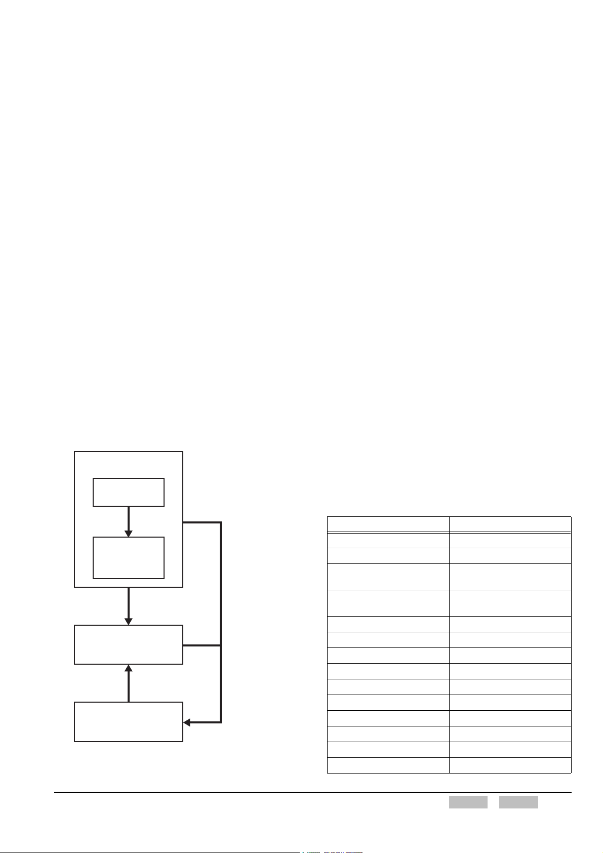
Function Reference
2 Basic Operation
Refer to other
section if
necessary.
3 Display function
to
23 Mode function
Program data
using the
KPG-95D.
Field Programming
Reference
Edit the program
after modifying
the transceiver.
Modification Information
Figure 1 Basic Operations Flow
Install the optional
board, such as a Voice
Scrambler board, to
the transceiver.
Modified Terms in TK-5210
In the in-depth manual, conventional ambiguous function
names, function names that do not correspond to
operations, grammatical mistakes, and non-unique terms
are revised. Therefore, some function names were
changed even though the operations have not changed.
Refer to the comparison list for new and old function
names.
New Description Description in the Past
2-tone 2 Tone
2-tone 2-Tone
3 Reference Level
Adjustments
5 Reference Level
Adjustments
5-tone 5 Tone
Autodial Auto Dial
Battery Saver Battery Save
Cl e a r t o Ta lk Cl e a r To Ta l k
End of Transmission End Of transmission
Key Beep Key Press Tone
Key-entry Error Tone Key Input Error Tone
Low transmit Power Low Power
Low transmit Power RF Power Low
Manual Dialing Manual Dial
3 Point Tuning
5 Point Tuning
FUNC (K)/Ver. 1.02 Confidential Contents Index I

New Description Description in the Past
Off-hook Off Hook
On-hook On Hook
Optional Board Option Board
Optional Signaling Option Signalling
OST Status Memory OST Back Up
Password Authorization Tone password agreement Tone
Power-on Scan Power On Scan
Power-on Text Power On Text
Power-on Tone Power On Tone
Pre-alert Pre-Alert
Read Authorization Password Read Password
Receive Frequency RX Frequency
Ringer Tone Ringing Tone
Scrambler Status Memory Scrambler Backup
Sidetone Side Tone
Single Reference Level
Adjustment
Store & Send Store&Send
Stun-off Tone Stun Off Tone
Stun-on Tone Stun On Tone
Time-out Timer Time Out Timer
Tone Off (OST) Selectable No Tone
TOT T.O.T.
Transceiver Radio
Transceiver Password Radio Password
Transceiver-kill Radio-kill
Transmission Frequency TX Frequency
Transmission Power TX Power
Trunking Logic Board Trunking Board
Turn-off Code Turn off Code
Transmit Inhibit While
Receiving
Warning Tone Warning Alert Tone
While Transmitting On TX
Wide 4k Wide4k
Wide 5k Wide5k
Zone-name Text Length Zone Name Text length
1 Point Tuning
TX Inhibit on Receive
Abbreviations
The following abbreviations are used in the in-depth
manual since this manual was created in English.
Abbreviation Full Spelling or its Meaning
ACK Acknowledgement
AES Advanced Encryption Standard
ANI Board Automatic Number Identification Board
ANT Antenna
APCO
AQUA Kenwood's audio signal processing IC
AUX Auxiliary
BCL Busy Channel Lockout
BOT Beginning of transmit
CAI Common Air Interface
CC Control Channel
CCIR
CH Channel
CKR Common Key Reference
COM port Communication port
COR Carrier-operated Relay
CW Continuous Wave
Dec ID Decode ID code
deg degree (s)
Del Delete
DES DATA Encryption Standard
DQT Digital Quiet Talk
DR Direct Channel
DTMF Dual Tone Multiple Frequency
DYN Dynamic Regrouping
Enc ID Encode ID code
EOT End of transmit
ESN Electronic Serial Number
Ext. PTT An external PTT switch
FCC Federal Communications Commission
FDMA Frequency Division Multiple Access
FEC Forward Error Correction
FIFO First-in First-out
FILO First-in Last-out
FPU Field Programming Unit
GID Group ID code
GPS Global Positioning System
GTC Go to Channel
Hex Hexadecimal
Hi High
Association of Public-Safety
Communications Officials
Comité Consultatif International des
Radiocommunications
II Index Contents Confidential FUNC (K)/Ver. 1.02

Abbreviation Full Spelling or its Meaning
I/O Input/Output
IMBE Improved Multi-band Excitation
ISP Inbound Signaling Packets
KDS-100 Kenwood Data Terminal
KGP-2A/ KGP-2B GPS Receiver Modem Unit
KMM
LC Link Control Information
LDU Logical Link Data Units
LOK Link OK (connected to the repeater)
LRA Local Registration Area
LSD Low Speed Data
LTR I D
MFID Manufacturer ID
MI Message ID
MI2 Microphone Input II
Mic Microphone
Mid Medium
MK Multi-Key
MSK Minimum Shift Keying
NAC Network Access Code
NID Network ID
OP CODE Operation Code
OST Operator Selectable Tone
OTAR Over-the-air Re-keying
PA Public Address
PABX Private Automatic Branch Exchange
Per No. Personal Number
PF Programmable Function
Prv. Private
PSTN Public Switched Telephone Network
PTT Push-to-Talk
PTT ID PTT (Push-to-talk) ID code
QT Quiet Talk
RCM Radio Communications Management
RFSS ID RF Subsystem ID
RSSI Received Signal Strength Indication
RTC Real Time Clock
RX Reception, Receiver, Receive
RXD Received data
RXVCO Receiver's voltage controlled oscillator
SF State Flag
SID System ID
SU Subscriber Unit
Key Management Message
(APCO)
ID used in the Logic Trunked Radio
system
Abbreviation Full Spelling or its Meaning
SW Switch
SYS System
SYS ID System ID
Sys No. System Number
TA Talk Around
TEL Telephone
Thr. Threshold
TOR Tone-operated Relay
TOT Time-out Timer
TX Transmission, Transmitter, Transm it
TX LED Transmit LED
TXD Transmitted data
TXS Transmission Sense
TXVCO
UID Unit ID
UTC Universal Time Coordinated
VC Voice Channel
VCO Voltage Controlled Oscillator
VGS Voice Guidance and Storage
VGS-1 Voice Guidance and Storage Unit
VOC Voice on Control
Vocoder Voice Encoder/ Decoder
VOX Voice-operated Transmission
w/QT/DQT with QT and DQT signaling
w/STE With Squelch Tail Eliminator
WACN Wide Area Communication Network
WACN ID Wide Area Communication Network ID
WG ID Working Group ID
WU ID Working Unit ID
Transmitter's voltage controlled
oscillator
FUNC (K)/Ver. 1.02 Confidential Contents Index III

About Trademark
Microsoft, Windows®98, Windows®Me,
Windows
registered trademarks of Microsoft Corporation.
Other company names and product names are
trademarks or registered trademarks of the companies.
®2000, Windows®XP and Windows logo are
About the Programming Software
for TK-5210
The functions of the TK-5210 can be configured using
KPG-95D. The configuration data configured using KPG95D can be written in the transceiver by connecting the
TK-5210 to the PC using the KPG-36 cable. In this
manual, the description of each function in the Function
Reference may have a corresponding reference in the
Field Programming Reference. Therefore, you can
configure the function by referring to the corresponding
reference in the Field Programming Reference.
IV Index Contents Confidential FUNC (K)/Ver. 1.02

1 OUTLINE
1.1 Description of the TK-5210
The TK-5210 is a VHF portable transceiver. This
transceiver is designed for the P/S (Public Safety) market
and the transceiver features conventional analog FM
mode (Analog Conventional). This transceiver is also
compliant with the APCO Project 25 Standard specified
by the TIA-102.
There are 3 versions of TK-5210 transceiver equipped as
follows:
K-type: TK-5210 (K) Basic Model
K2-type: TK-5210 (K2) 4-key with LCD
K3-type: TK-5210 (K3) Full key set with LCD
Note:
TIA stands for Telecommunications Industry Association.
APCO stands for Association of Public safety Communication
Officials. This organization promotes the safety
communications in public. APCO Project 25 Standard is the
standard of the digital communications specified by P25.
1.2 Features of the TK-5210
The TK-5210 has the following features.
Transmit/ Receive
z The transceiver covers the VHF frequency range
of 136 MHz to 174 MHz.
z The transmit power is switchable 5 W and 1 W.
z The transceiver is equipped with a modem function
that utilizes DSP.
z A maximum of 250 channels can be configured to
each zone.
z A user can select P25 Conventional or Analog
Conventional on each channel.
z The transceiver is equipped with Monitor, Squelch
Off and VOX functions.
z The transceiver is equipped with Radio Inhibit/
Uninhibit function. (This function works in P25
Conventional Mode.)
z This transceiver supports conventional FleetSync
and FleetSync II enhanced with Error Correct
function in conventional FleetSync.
Emergency
z The transceiver is equipped with Emergency
function. (The operation of this function differs
between P25 Conventional Mode and Analog
Conventional Mode.)
z The transceiver can be equipped with an optional
Man-down switch (CAE-3).
Chassis
z The chassis complies with water-resistance
specifications, such as IP66, IP67 and MIL
Immersion. (Optional accessories are required.
The transceiver meets IP54/ 55 specifications
when it is shipped.)
z This transceiver complies with all 12 items
specified by MIL-810 C/ D/ E/ F and features
robust construction.
PF Key (Programmable Function Key)/
Switch
z The TK-5210 comes equipped with the following
PF keys and switch.
• Selector (16 positions)
• Concentric switch (3 positions)
• Lever switch (2 positions)
• Orange key
• 3 PF keys (Left Side)
• 4 PF keys (Front panel) (K2- or K3-type only)
• 12-key keypad (K3-type only)
Scan
z The transceiver can scan in both P25
Conventional Mode and Analog Conventional
Mode.
z The transceiver features Dual Priority Scan using 2
Priority Channels.
Display (K2- or K3-type only)
z The transceiver is equipped with a full dot matrix
display (43 dots x 96 dots). The LCD features the
main display, the sub-display, and various icons
and key guides.
z This transceiver has a function to display the
remaining battery life.
Battery
z The battery life of the 1700 mAh Ni-cd battery is
approximately 8 hours. The battery life may be
reduced if an optional board is installed in the
transceiver.
z This transceiver supports a 1700 mAh Li-ion battery
(optional accessory).
z This transceiver supports a 2500 mAh Ni-MH
battery (optional accessory). The battery life of
this battery type is 12 hours. (5 minutes transmit, 5
minutes receive, 90 minutes standby, and when an
optional board is not installed.)
FUNC (K)/Ver. 1.02 Confidential Contents Index 1
1 OUTLINE
Scalability
z The following optional boards are available. These
boards can be installed at the same time.
• Voice Scrambler: SC20-460 (Transcrypt)
• ANI Board: QE-2 (Cimarron)
Communication
z The transceiver is equipped with Clone function
allowing a user to copy configuration data to
another transceiver. (This function is only
available when the optional Clone cable is used.)
Other Functions (K2- or K3-type only)
z This transceiver is equipped with an RTC (Real
Time Clock). (RTC error is less than 30 seconds
per month at room temperature.)
z The transceiver is equipped with the Read
Authorization Password/ Overwrite Password
function.
Orange key
Press this PF key to activate the programmed
function.
Transmit/ Receive/ Battery Low indicator (LED)
The LED indicates the status of the transceiver.
• When the LED lights red:
The transceiver is transmitting. (Refer
to 3.8 Transmit LED on page 28.)
• When the LED lights green:
The transceiver is receiving. (Refer to
3.7 Busy LED on page 28.)
• When the LED is flashing red:
The LED flashes red when the battery
level is too low while transmitting.
(Refer to 3.10 Battery Status/ Warning
on page 29.)
Signaling indicator (LED)
The LED flashes orange when the Optional Signaling
is matched. (Refer to 7 SIGNALING FUNCTION on
page 36.)
Table 1-1 Compliance with Signalings (Analog Mode)
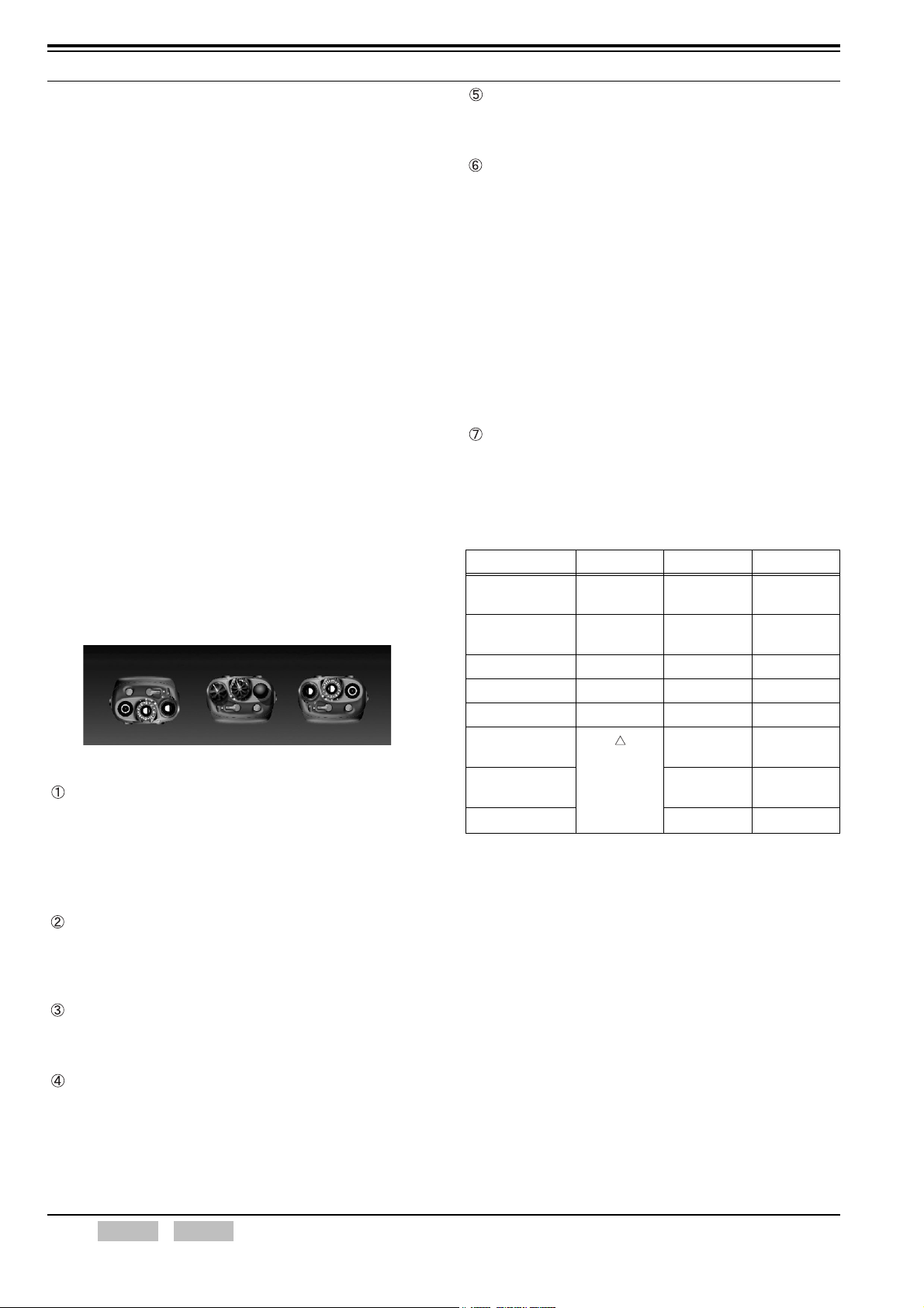
1.3 Functions and Panel Layout
Top Panel (K2- or K3-type only)
Figure 1-1 Top Panel
Power switch/ Volume control
Turning this switch clockwise to switch ON the
transceiver.
The volume increases while turning the Volume
control clockwise and the volume decreases while
turning the Volu me control counterclockwise.
Selector (16 positions)
Turning the Selector to activate the programmed
functions. This Selector can change the Zone or
Channel.
Concentric switch (3 positions)
Select different switch positions (A/ B/ C) to activate
the programmed functions.
Signaling K type K2-type K3-type
QT Encode/
Decode
DQT Encode/
Decode
2-tone Decode O O O
DTMF Encode O O O
DTMF Decode O O O
FleetSync
Encode/ Decode
FleetSync II
Encode/ Decode
OST O O
OOO
OOO
Functions
relevant to
the display
are not
supported.
OO
OO
Lever switch (2 positions)
Toggle the switch (Front/ Rear) to activate the
programmed function. Moving the switch to front
position disables the programmed function and
moving the switch to rear position enables the
function.
2 Index Contents Confidential FUNC (K)/Ver. 1.02
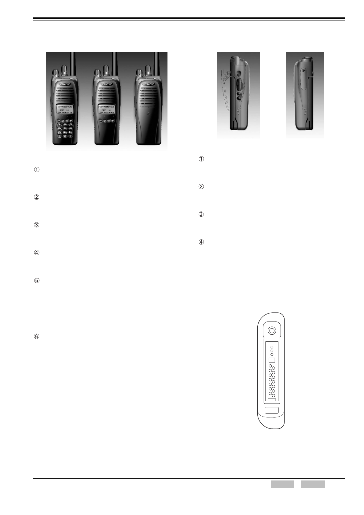
1 OUTLINE
Front Panel
Figure 1-2 Front Panel
[A] key (K2- and K3-type)
Press this key to activate the corresponding
programmed function.
[B] key (K2- and K3-type)
Press this key to activate the corresponding
programmed function.
[<C] key (K2- and K3-type)
Press this key to activate the corresponding
programmed function.
[D>] key (K2- and K3-type)
Press this key to activate the corresponding
programmed function.
12-key keypad (K3-type)
This keypad has 12 keys: [#], [*] and [0] to [9] keys.
The transceiver transmits the corresponding DTMF
code when a key is pressed. This keypad can be
used to select the status number and list number in
FleetSync. (Refer to 2.17 Keypad Operation (K3-type
only) on page 24.)
Side Panel (common to K2- and K3-type)
Figure 1-3 Side Panel
Side 1 key
Press this key to activate the corresponding
programmed function.
PTT switch
Press this switch to make a transmission. Speak into
the microphone while pressing the PTT switch.
Side 2 key
Press this key to activate the corresponding
programmed function.
Side 3 key
Press this key to activate the corresponding
programmed function.
14-pin Universal Connector
The 14-pin connector is available on the TK-5210
transceiver and you can connect external devices to
this connector.
LCD (K2- and K3-type)
The activated zone and channel appears on the
display.
135791113
2468101214
Figure 1-4 14-pin Universal Connector
FUNC (K)/Ver. 1.02 Confidential Contents Index 3

1 OUTLINE
Table 1-2 14-pin Universal Connector Pin Assignment
Pin
number
1 SSW Ext/Int Speaker Switch input
2 SP+ BTL Output + for External Speaker
3 SP- BTL Output - for External Speaker
4 MSW Ext/Int Mic Switch input
5 EMC Ext Mic input
6 ME External Mic GND
7 PTT External PTT input
8 PF Programmable Function Key input
9 OPT AUX I/O port (for External Option)
10 E GND
11 5M 5 V
12 TXD Serial Data Output
13 RXD Serial Data Input
14 NC (E) Not use (GND)
Name Functio
1.4 Description of Zone/ Channel
A zone consists of channels configured with transmit
frequency and receive frequency. KPG-95D allows you
to configure Analog Conventional System channels or
P25 Conventional System channels to each zone.
A maximum of 50 zones can be configured. A maximum
of 250 channels can be configured to each zone.
Zone Data
Zone Data
Zone Data
Zone Data
Zone Data
Zone Data
Channel
Figure 1-5 Zone/ Channel Configuration
Configure a Personality and assign the Personality Data
to a channel in each zone. You can assign the same
Personality to multiple channels so that a user does not
need to configure the same frequency data repeatedly.
A configured Personality does not need to be assigned
immediately to each channel. Therefore, you can assign
the Personality to a channel easily once the basic
System/ Personality is configured for each other.
Link
System Data
Personality Data
Configuration using KPG-95D
z Configuring the Zone/ Channel (Refer to FPRG
6.5 Zone/ Channel Parameters Window.)
4 Index Contents Confidential FUNC (K)/Ver. 1.02
1 OUTLINE
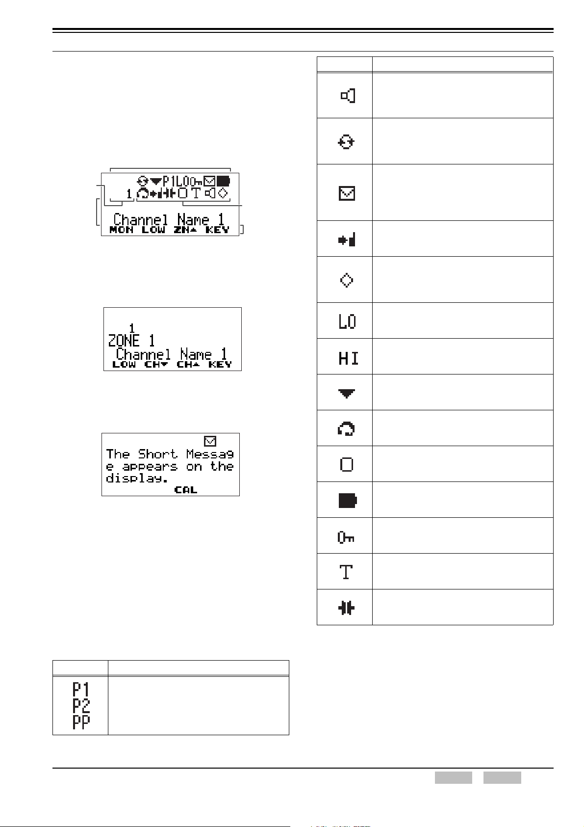
1.5 Display (K2- or K3-type only)
The K2- and K3-type transceiver are equipped with an
LCD display. Activated Zone/ Channel and functions
appear on the display as icons and they represent the
current status of the transceiver. Received messages
also appear on the display.
Icon display area
Sub display
Main
display
Figure 1-6 Standard Standby Display
Icon display
area
Key Guide
area
Standard Display (2-digit Display)
Figure 1-7 2-digit Display
Message Display (3-digit Display)
Figure 1-8 3-digit Display
1.6 Icons
The following icons are used by the TK-5210 to display
the status of the transceiver. Each icon appears in the
icon display area of the transceiver.
Icon Description
This icon indicates 2 statuses of the transceiver.
• Monitor On (Refer to 7.5 Monitor on page 38.)
• Squelch Off (Refer to 7.6 Squelch Off (Analog
Conventional) on page 39.)
This icon indicates 2 statuses of the transceiver.
(Refer to 13 SCAN FUNCTION on page 59.)
• While receiving
• While the scan pauses.
This icon indicates that the transceiver received
the FleetSync Short Message or Status
Message.
(Refer to 16.3 Status Message on page 82,
16.4 Short Message Function on page 88.)
This icon indicates that the Talk Around function
is enabled. (Refer to 5 TALK AROUND
FUNCTION on page 34.)
This icon indicates that the Voice Scrambler
function or Encryption function is enabled.
(Refer to 12 VOICE SCRAMBLER FUNCTION
on page 57, 22 P25 FUNCTION on page 122.)
This icon indicates that the transmit power is
switched to Low Transmit Power. (Refer to 2.7
Transmit Power on page 18.)
This icon indicates that the transmit power is
switched to High Transmit Power. (Refer to 2.7
Transmit Power on page 18.)
This icon indicates that the current channel is
included in the scan list during the scan.
(Refer to 13 SCAN FUNCTION on page 59.)
This icon indicates that the VOX function is
enabled. (Refer to 11 VOX (VOICE
OPERATED TRANSMISSION) on page 54.)
This icon indicates that the OST function is
enabled. (Refer to 14 OST FUNCTION (K2-
AND K3-TYPE ONLY) on page 66.)
This icon indicates the remaining life of the
battery. (Refer to 3.10.1 Battery Status on page
30.)
This icon indicates that the keys on the
transceiver are locked. (Refer to 2.16 Key Lock
on page 23.)
This icon indicates that the transceiver is in
Tactical Group Configuration Mode. (Refer to
21 KEY ASSIGNMENT on page 113.)
This icon indicates that the Compander function
is enabled. (Refer to 2.15 Compander on page
22.)
Table 1-3 Available Icons
Icon Description
This icon indicates the current Priority Channel.
(Refer to 13 SCAN FUNCTION on page 59.)
P1: Priority Channel 1
P2: Priority Channel 2
PP: Priority Channels 1/ 2
FUNC (K)/Ver. 1.02 Confidential Contents Index 5

1 OUTLINE
1.7 Key Guide
The following annunciators appear on the display in the
TK-5210. Each annunciator appears on the key guide
area on the transceiver.
Table 1-4 List of Key Guide
Keys Annunciator
None Nothing displayed.
Autodial (K2- or K3-type only) AD
Battery Status BAT
Call Response RES
Channel Down CH
Channel Recall RCL
Channel Up CH
Clock (K2- or K3-type only) CLK
Direct Channel 1 DC1
Direct Channel 2 DC2
Direct Channel 3 DC3
Direct Channel 4 DC4
Direct Channel 5 DC5
Display Character (K2- or K3-type only) CHR
Emergency EMG
External Speaker ESP
Function FNC
Home Channel HOM
Individual (P25) IDV
Key Delete KDL
Key Lock LCK
Light (K2- or K3-type only) LIT
Low Transmit Power LOW
Monitor MON
Monitor Momentary MON
Operator Selectable Tone OST
OST Down OS
OST Up OS
Page PAG
Scan SCN
Scan Delete DEL
Scan Program SCP
Scrambler/ Encryption SE
Scrambler/ Encryption Code (K2- or K3type only)
Selcall (K2- or K3-type only) SEL
Selcall Status (K2- or K3-type only) SES
Site Lock SIT
Squelch Level SQL
SEC
Squelch Off MON
Squelch Off Momentary MON
Status (K2- or K3-type only) STS
System Search SRC
Tactical Group TAC
Talk Around TA
Talkgroup TGR
Tone TON
VOX VOX
Zone Down ZN
Zone Up ZN
Table 1-5 Multi-operation (mode) display
Announciator Keys
SET Set
MNU Menu
DEL Delete
CHG Change
ESC Escape
CAL Call
CAN Cancel transmission
BAK Back
YES Yes
NO No
REC Record
PLY Play
STP Stop
SEL Select
SND Sending Data (Clone mode)
CNF Password Confirmation
*1
*1
FRQ Frequency (Self-Programming mode)
QT QT (Self-programming mode)
DQT DQT (Self-programming mode)
NXT Next (Self-programming mode)
NAC
MSG Short Message display mode selection
*1:
Used in the VOX Gain/ Squelch Level/ Encryption Code.
Down (VOX Gain)
Up (VOX Gain)
NAC/ Talk Group selection (Selfprogramming mode)
6 Index Contents Confidential FUNC (K)/Ver. 1.02
1 OUTLINE
1.8 Tone Pattern
The transceiver emits a beep tone when the transceiver is
turned ON, a PF key is pressed or an error occurs. The
transceiver can also transmit the Transpond tone to the
caller when the transceiver receives a call.
1.8.1 Beep Tone
The TK-5210 emits the following tones.
KPG-95D can configure the volume level of each tone.
(Refer to 4.4 Tone Volume on page 32.)
Power-on Tone
The transceiver emits this tone when the transceiver is
turned ON.
Frequency 1477 Hz
Length 500 ms
Alert Tone
z User Program Alert Tone
A maximum of 8 tones can be configured or
changed. (Refer to 4.5 Alert Tone Pattern on page
33.)
z Key-entry Error Tone
The transceiver emits this tone when a key is
pressed and denied. This tone also emits when a
key with no assigned function is pressed.
Frequency 697 Hz
Length 100 ms
z Rollover Tone
The transceiver emits this tone when a key is
pressed and accepted. This tone also emits when
the lowest Zone/ Channel Number is selected.
Frequency 1633 Hz
Length 200 ms
z Password Authorization Tone
The transceiver emits this tone when the entered
password is correct.
Frequency 1633 Hz 1633 Hz
Length 50 ms 50 ms 50 ms
Control Tone
z Key Beep A
The transceiver emits this tone when a key is
pressed and accepted. The transceiver also emits
this tone when a function is enabled with the toggle
key.
Frequency 1633 Hz
Length 50 ms
z Key Beep B
The transceiver emits this tone when a key is
pressed and accepted. The transceiver also emits
this tone when a function is disabled with the
toggle key.
Frequency 1633 Hz 1633 Hz
Length 50 ms 50 ms 50 ms
z Key Beep C
The transceiver emits this tone when a key is
pressed and accepted. This tone also emits when
writing data, such as DTMF Memory or Test Mode
adjustment values, to the transceiver.
Frequency
Length 50 ms 50 ms 50 ms 50 ms 50 ms
1633
Hz
1633
Hz
1633
Hz
FUNC (K)/Ver. 1.02 Confidential Contents Index 7
1 OUTLINE
z Priority Channel Tone
The transceiver emits this tone when scan pauses
on the Priority Channel. (Refer to 13 SCAN
FUNCTION on page 59.)
Frequency 2000 Hz
Length 50 ms
z Scan Stop Tone
The transceiver emits this tone every 5 seconds
when the channel is changed with the Home
Channel key or Direct Channel key and scan
stops.
Frequency 700 Hz 700 Hz
Length 50 ms 50 ms 50 ms
z VOX Proceed Tone
The transceiver emits this tone when the
transceiver transmits using the VOX function.
(Refer to 11 VOX (VOICE OPERATED
TRANSMISSION) on page 54.)
Frequency 1550 Hz
Length 30 ms
Sidetone
z PTT ID Sidetone
The transceiver emits this tone when the
transceiver sends the PTT ID in FleetSync. (Refer
to 16.1 PTT ID on page 76.)
Frequency 1209 Hz 1633 Hz 1209 Hz 1633 Hz
Length 30 ms 30 ms 30 ms 30 ms
Locator Tone
z Locator Tone
The transceiver emits this tone before or after the
transmission when the transceiver makes an
automatic transmission in Emergency Mode.
(Refer to 15.4 Duration of Locator Tone 1 on page
73.)
Frequency 1633 Hz 941 Hz
Length 90 ms 90 ms
Warning Tone
z Warning Tone
The transceiver emits Warning Tone in the
following conditions. The transceiver emits this
tone continuously until the following conditions are
reset.
• When the transceiver finishes a transmission
with the Time-out Timer. (Refer to 6 TIME-
OUT TIMER (TOT) FUNCTION on page 35.)
• When an unprogrammed zone or channel is
selected using the Selector.
• While the Busy Channel Lockout function
activates. (Refer to 2.9 Busy Channel Lockout
on page 19.)
Frequency 697 Hz
Length
The transceiver keeps emitting this tone
until the specified conditions are reset.
z TOT Pre-alert Tone
The transceiver emits this tone to notify a user that
the transmission is going to be restricted by the
Time-out Timer. (Refer to 6.1 TOT Pre-alert on
page 35.)
Frequency
Length 50 ms 50 ms 50 ms 50 ms 50 ms
1633
Hz
1633
Hz
z Battery Warning Tone
The transceiver emits this tone when the battery
level is lower than the configured threshold level
while receiving. (Refer to 3.10.2 Battery Warning
on page 30.)
Frequency 697 Hz 697 Hz 697 Hz
Length 50 ms 50 ms 50 ms 50 ms 50 ms
z PLL Unlock Tone
The transceiver emits this tone when the PLL
circuit is unlocked.
Frequency 1400 Hz
Length 50 ms
Configuration using KPG-95D
z Configuring the volume level of Beep Tone (Refer
to FPRG
z Configuring the User Program Alert Tone (Refer to
FPRG 6.10 Special Alert Tone Window.)
Tone Volume Offset.)
1633
Hz
8 Index Contents Confidential FUNC (K)/Ver. 1.02

1.8.2 Transpond Pattern
The TK-5210 emits the following Transpond tones.
Transpond Tone
The transceiver emits the Transpond tone when the
transceiver receives a call using DTMF or 2-tone. The
transceiver only modulates this tone and does not
emit the tone from the speaker.
Frequency 2100 Hz
Length 1 s
Stun On Tone
The transceiver emits the Transpond tone when the
transceiver receives the Stun code and the
transmission is restricted. The transceiver only
modulates the tone and does not emit this tone from
the speaker.
Frequency 1470 Hz
Length 2 s
1 OUTLINE
Stun Off Tone
The transceiver emits the Transpond tone when the
transceiver receives the code used to disable the Stun
function while transmission is restricted by the Stun
function. The transceiver only modulates this tone
and does not emit the tone from the speaker.
Frequency 1470 Hz 1470 Hz
Length 2 s 500 ms 2 s
FUNC (K)/Ver. 1.02 Confidential Contents Index 9
2 BASIC OPERATION
2.1 Turning the Transceiver ON/ OFF
Turn the Power switch clockwise to turn ON the
transceiver. The transceiver is turned OFF when turning
the Power switch counterclockwise until it clicks. The
operation of the transceiver when the transceiver is
turned ON/ OFF varies depending on how the transceiver
was configured with KPG-95D.
The transceiver is turned ON after turning the Power
switch clockwise or installing the battery after turning the
Power switch clockwise. In each case, all segments of
the LCD and LEDs light and the Power-on Tone sounds
for 500 ms.
After the transceiver beeps, it transfers the firmware for
DSP IC, diagnoses and verifies the available frequency
data for the channels for several seconds.
All dots lit
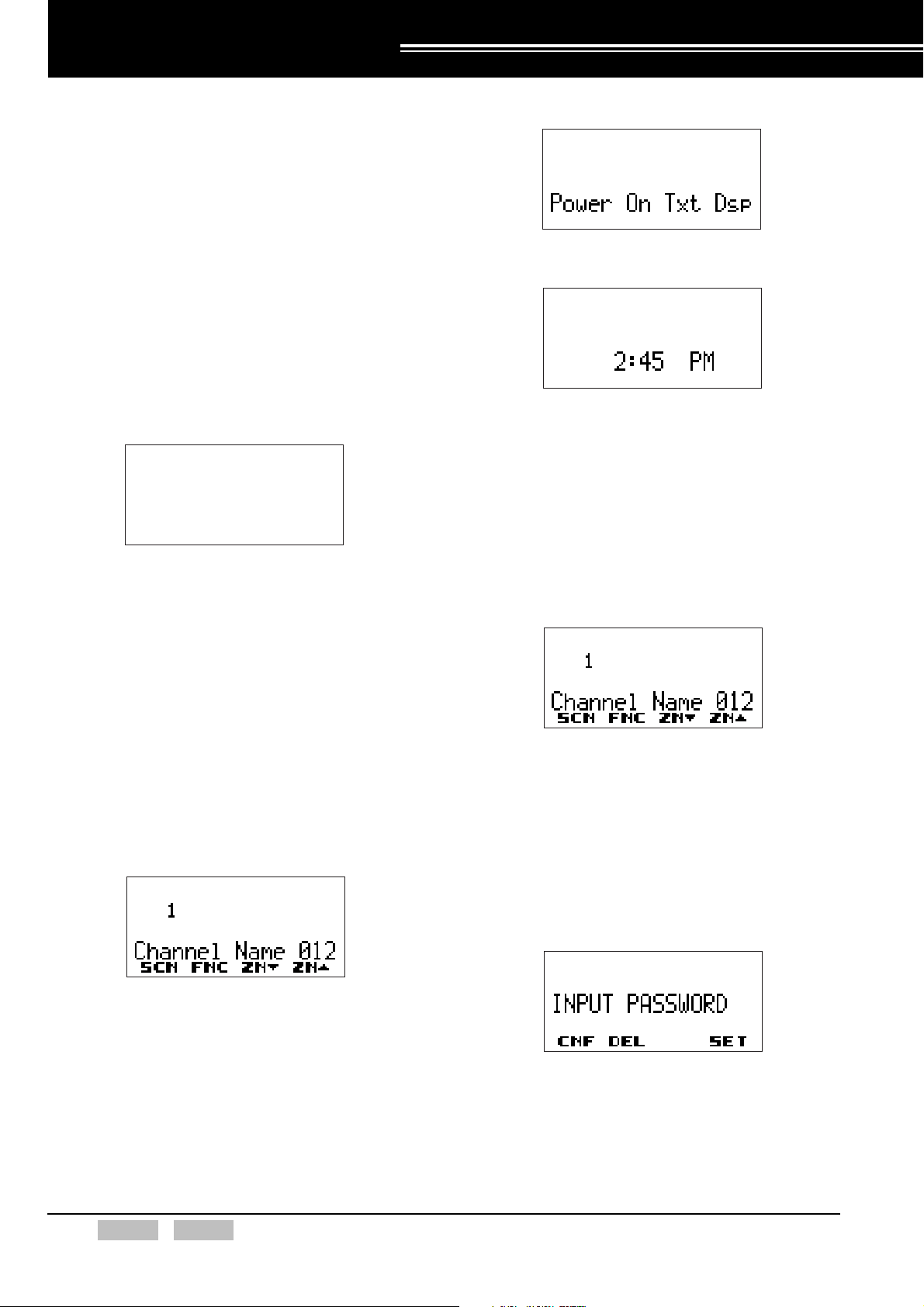
z Power-on Text configured:
z Power-on Clock configured:
Note:
The Zone/ Channel name or number appears when
the time is not configured even if the Power-on
Clock is configured in the transceiver.
The Zone/ Channel name or number appears if a
key other than the Light key or Function key is
pressed. The transceiver enters Emergency Mode
when the Emergency key is pressed.
Figure 2-1 Status of the Display When the
Transceiver is Turned ON.
Note:
There is no display on the K-type transceiver.
Key functions are temporarily disabled while the transceiver is
turning ON/ OFF.
2.1.1 Turning the Transceiver ON
No Function Configured:
1. Turn the transceiver ON.
2. The Zone/ Channel name or number appears on
the display.
Power-on Text or Power-on Clock
Configured (K2- or K3-type only):
(Refer to 3.6 Power-on Text on page 28, 17.2
Displaying the Time when the Transceiver is Turned
ON on page 104.)
1. Turn the transceiver ON.
2. The text or clock configured in the transceiver
appears on the display for 2 seconds.
3. The Zone/ Channel name or number appears on
the display.
Transceiver Password Configured (K2- or
K3-type only):
(Refer to 2.11 Transceiver Password (K2- or K3-type
only) on page 20.)
1. Turn the transceiver ON.
2. The Transceiver Password Entry window
appears on the display.
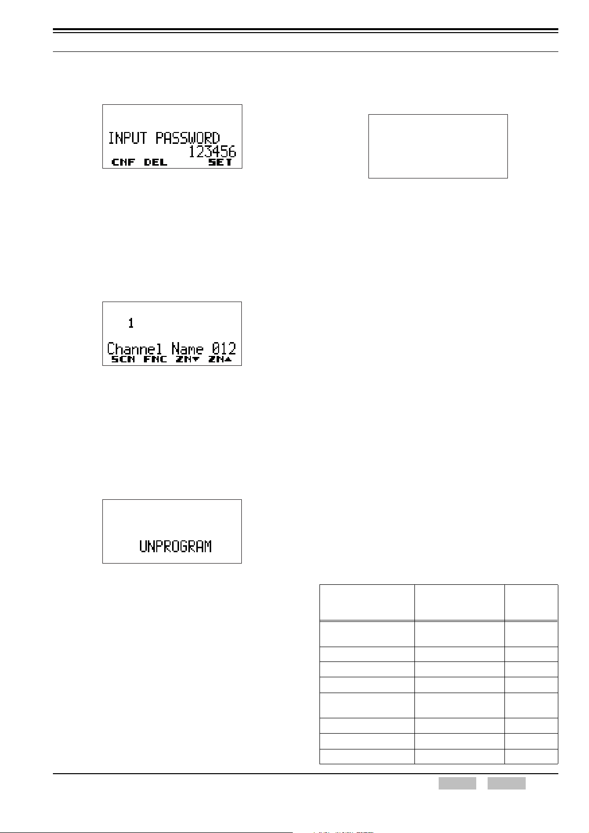
“INPUT PASSWORD” appears on the display.
10 Index Contents Confidential FUNC (K)/Ver. 1.02
2 BASIC OPERATION
3. Enter the password using the keypad or PF keys.
(Refer to 2.11 Transceiver Password (K2- or K3type only) on page 20.)
Note:
The entered password is verified when the [A] key
or [*] key (K3-type only) is pressed.
After entering a wrong password, the Key-entry
Error Tone sounds and the display returns to the
Transceiver Password Entry window.
4. The Password Authorization Tone sounds when
the entered password is correct and the Zone/
Channel name or number appears on the display.
When the Power-on Text or Power-on Clock is
configured to the transceiver, the text or clock
appears on the display for 2 seconds. Then, the
Zone/ Channel name or number appears on the
display.
Transceiver Inhibit Function Enabled:
1. Turn the transceiver ON.
2. No items appear on the display.
Note:
The Radio Inhibit function disables operation of the
transceiver with an over-the-air command.
Therefore, the transceiver is actually turned ON
even though it appears to be turned OFF. To
disable Radio Inhibit, the transceiver must receive
the Transceiver Uninhibit command.
The transceiver starts the same operation when the
transceiver is turned ON.
Configuration using KPG-95D
z Configuring the Power-on Text (Refer to FPRG
6.6.1 Common Page 1 Tab.)
z Configuring the Power-on Clock (Refer to FPRG
6.6.2 Common Page 2 Tab.)
z Configuring the Transceiver Password (Refer to
FPRG 6.6.1 Common Page 1 Tab.)
z Configuring the Radio Inhibit Function (Refer to
FPRG 6.2.4 Advanced Tab.)
No Available Frequency Data:
1. Turn the transceiver ON.
2. “UNPROGRAM” appears on the display.
Firmware Data Not Configured:
The transceiver automatically enters Firmware
Programming Mode when the transceiver is turned
ON.
2.1.2 Turning the Transceiver OFF
Turn the Power switch counterclockwise until it clicks to
turn OFF the transceiver. The transceiver is also turned
OFF when the battery is removed from the transceiver.
Some of the transceiver’s configuration parameters are
stored even after the transceiver is turned OFF.
Only the clock function continues after the transceiver is
turned OFF.
Table 2-1 Stored Configurations
Stored KPG-95D
Function
Scrambler (SC20-460)
VOX Gain Level No Off
Squelch Level No 1
Scan Switch No Off
Test Channel/ Signaling
Number
Last Channel No Off
Key Lock No Off
Stun No Off
Configuration
Parameters
Scrambler
configuration is stored.
No Ch1 - Sig1
Default
Off
FUNC (K)/Ver. 1.02 Confidential Contents Index 11

2 BASIC OPERATION
Stored KPG-95D
Function
OST
Low Transmit Power No Off
FleetSync Message
Stack
Tactical Group No Off
Clock No On
Display Character No Off
Monitor No Off
Squelch Off No Off
Scan Delete No Off
Note: The transceiver cannot be turned OFF when the Suspended
Power-off function is enabled while the transceiver is in
Emergency Mode.
Configuration
Parameters
OST configuration is
stored.
FleetSync Message
Stack configuration is
stored.
Default
Off
Off
The only channel name appears on the display for
2 seconds.
3. “**********” appears on the display and Warning
Tone sounds when a zone that is not configured in
the transceiver is selected.
2.2 Selecting the Zone
Zone consists of channels with configured transmit
frequency and receive frequency. A user can select the
zone using the Selector and PF keys.
2.2.1 Selecting the Zone using the Selector
Assign the Zone Select function to the Selector. (Refer
to 21 KEY ASSIGNMENT on page 113.)
A user can increase the zone number by turning the
Selector clockwise and decrease the zone number by
turning the Selector counterclockwise.
The user can select the zone number from 1 to 16 using
the Selector.
The user can display or hide the zone name. Transceiver
operation after selecting the zone varies depending on
configuration.
Transceiver Operation
z Zone Name Configured to be Displayed:
1. Select the zone by turning the Selector.
2. The new zone name appears on the first line of the
display with the channel name when a new zone is
selected.
If a zone with data is selected, the transceiver
functions as stated in step 2.
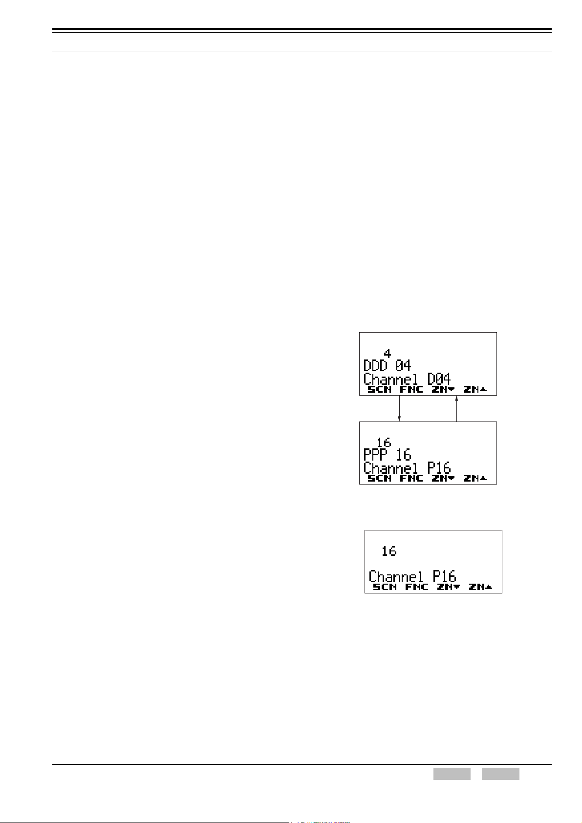
z Zone Name Configured to be Hidden:
1. Select the zone by turning the Selector.
2. The previous channel name used for a new zone
appears on the display when the new zone is
selected.
Note: The smallest channel number in the new zone is
selected if KPG-95D configuration data already has
been written into the transceiver.
3. Warning Tone sounds when a zone that is not
configured in the transceiver is selected.
If a zone with data is selected, the transceiver
functions as stated in step 2.
Configuration using KPG-95D
z Assigning the Zone Select Function to the
Selector (Refer to FPRG 6.8 Key Assignment
window.)
z Configuring the Zone Name to be Displayed or
Hidden (Refer to FPRG 6.6.1 Common Page 1
Tab.)
z Configuring the Zone/ Channel (Refer to FPRG
6.5 Zone/ Channel Parameters Window.)
12 Index Contents Confidential FUNC (K)/Ver. 1.02
2 BASIC OPERATION
2.2.2 Selecting the Zone using the Concentric Switch
When the Zone Select funstion is assigned to one of the
positions of the Concentric switch, the same function is
assigned to the other 2 positions of the switch (Co). In
this case, any zone can be configured to A, B and C
positions.
When the Concentric switch is positioned where the
Zone Select function is configured, the transceiver jumps
to the configured zone.
Note: When the Zone Select function is assigned to the
Concentric switch, the Zone Select function cannot be
assigned to the Lever switch. In this case, the Zone Select
function can be assigned to the Selector.
Configuration using KPG-95D
z Assigning the Zone Select Function to the
Concentric switch (Refer to FPRG 6.8 Key
Assignment Window.)
2.2.3 Selecting the Zone using the Lever Switch
2.2.4 Selecting the Zone using PF keys
Assign the Zone Up/ Zone Down functions to one of the
PF keys (Refer to 21 KEY ASSIGNMENT on page 113.)
A user can increase the zone number by pressing the
Zone Up key and decrease the zone number by pressing
the Zone Down key. The zone number automatically
changes by pressing and holding Zone Up or Zone
Down key for more than 1 second. The Rollover Tone
beeps when the smallest zone number is selected.
(Refer to 1.8.1 Beep Tone on page 7.)
The user can display or hide the zone name. Transceiver
operation to select the zone varies depending on
configuration.
Transceiver Operation
z Zone Name Configured to be Displayed:
1. Press the Zone Up or Zone Down key once.
The new zone name appears on the first line of the
display for 2 seconds.
When the Zone Select function is assigned to the Lever
switch, any zone can be configured for positions A and B.
When the Lever switch is positioned on the position
where the Zone Select function is configured, the
transceiver jumps to the configured zone.
Note: When the Zone Select function is assigned to the Lever
switch, the Zone Select function cannot be assigned to the
Concentric switch. In this case, the Zone Select function
can be assigned to the Selector.
Configuration using KPG-95D
z Assigning the Zone Select function to the Lever
switch (Refer to FPRG 6.8 Key Assignment
Window.)
Press the Zone Up key. Press the Zone Down key.
2. Only the channel name appears on the display in 2
seconds.
z Zone Name Configured to be Hidden:
1. Press the Zone Up or Zone Down key once.
The previous channel name used for a new zone
appears on the display when the new zone is
selected.
FUNC (K)/Ver. 1.02 Confidential Contents Index 13

2 BASIC OPERATION
2.3 Selecting a Channel
A user can select the desired channel using the Selector
or the PF keys.
Press the Zone Up key. Press the Zone Down key.
Configuration using KPG-95D
z Configuring the Zone Name to be Displayed or
Hidden (Refer to FPRG 6.6.1 Common Page 1
Tab.)
z Configuring the Zone/ Channel (Refer to FPRG
6.5 Zone/ Channel Parameters Window.)
z Configuring the Zone Up/ Zone Down functions
(Refer to FPRG 6.8 Key Assignment Window.)
2.2.5 Operations after Selecting a New Zone
The transceiver pauses scanning if the zone is changed
during scan operation. The transceiver resumes
scanning after 1 second. The transceiver’s operation
varies in the following way.
2.3.1 Selecting the Channel using the Selector
Assign the Channel Select function to the Selector of the
transceiver. (Refer to 21 KEY ASSIGNMENT on page
113.)
Transceiver Operation
A user can increase the channel number by turning
the Selector clockwise and decrease the channel
number by turning the Selector counterclockwise.
The user can select the channel number from 1 to 16
using the Selector.
Turn the Selector
clockwise.
Turn the Selector
counterclockwise.
Auto Scan Function Configured on the
Selected Channel:
(Refer to 13 SCAN FUNCTION on page 59.)
The transceiver starts scanning after the Key Delay
Time has elapsed.
Operations while scanning by pressing the
Scan key:
(Refer to 21 KEY ASSIGNMENT on page 113.)
z Scanning Initiated by Pressing the Scan key:
The transceiver pauses scanning. The transceiver
starts scanning after the Key Delay Time has
elapsed when selecting a channel configured in
the Scan List.
z Selected Channel Configured in the Scan List:
The transceiver starts scanning from the first
channel in the Scan List after the Key Delay Time
has elapsed.
“**********” appears on the display and Alert Tone
sounds when selecting a channel that is not
configured in the transceiver. Warning Tone stops
sounding and the channel name of the selected
channel appears on the display when selecting the
channel that is configured to the transceiver.
Turn the Selector
clockwise.
Turn the Selector
counterclockwise.
14 Index Contents Confidential FUNC (K)/Ver. 1.02
2 BASIC OPERATION
Configuration using KPG-95D
z Configuring the Zone/ Channel (Refer to FPRG
6.5 Zone/ Channel Parameters Window.)
z Configuring the Channel Select Function (Refer to
FPRG 6.8 Key Assignment Window.)
2.3.2 Selecting the Channel using PF keys
Assign the Channel Up/ Channel Down functions to one
of the PF keys. (Refer to 21 KEY ASSIGNMENT on page
113.)
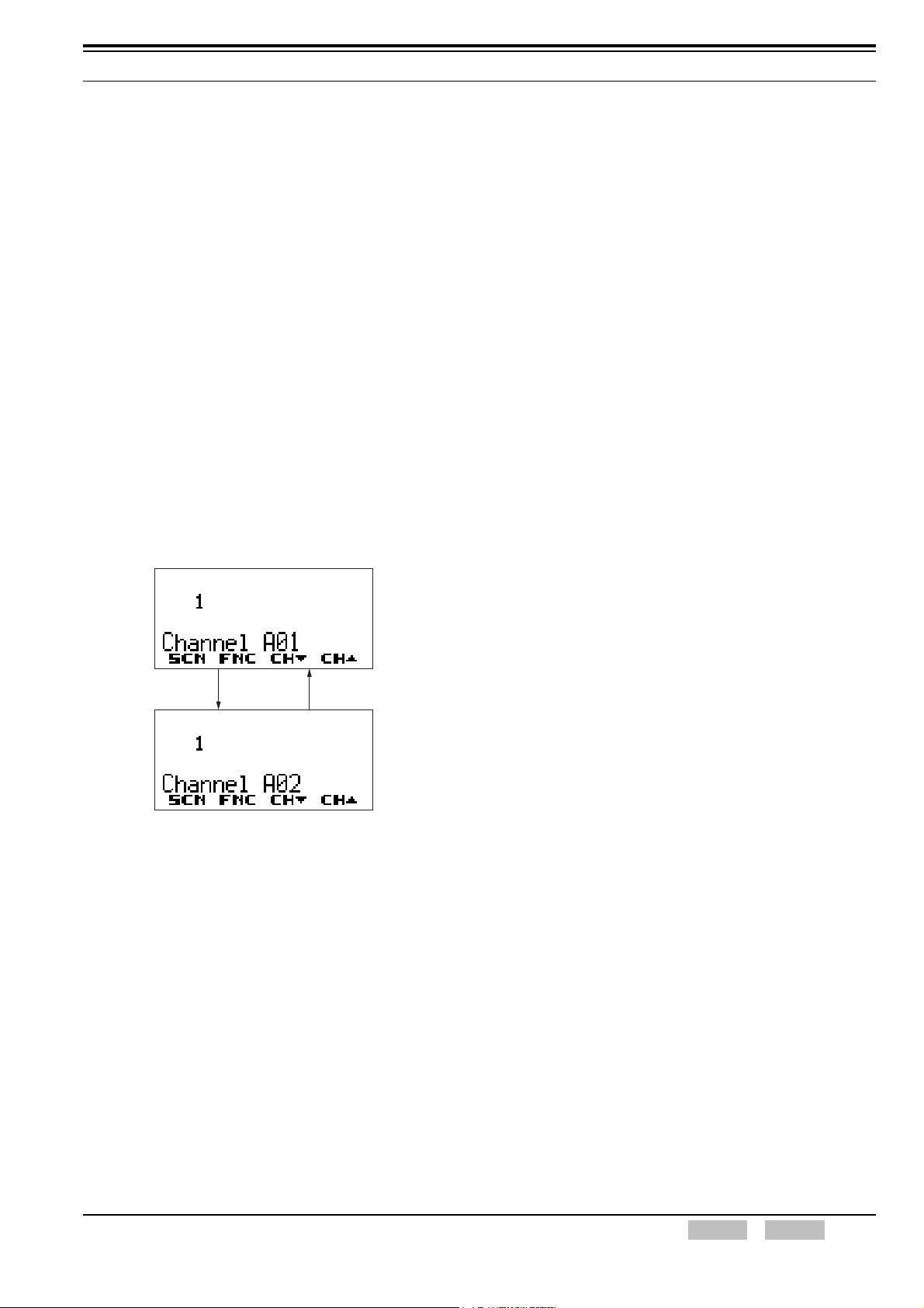
Transceiver Operation
A user can increase the channel number by pressing
the Channel Up key and decrease the channel
number by pressing the Channel Down key. The
channel number automatically changes in 0.1 second
increments when pressing and holding the Channel
Up or Channel Down key for more than 1 second.
The Rollover Tone beeps when the smallest channel
number is selected. (Refer to 1.8.1 Beep Tone on
page 7.)
Auto Scan Function Configured on the
Selected Channel:
(Refer to 13 SCAN FUNCTION on page 59.)
The transceiver starts scanning after the Key Delay
Time has elapsed.
Scanning Initiated by Pressing the Scan
key:
(Refer to 21 KEY ASSIGNMENT on page 113.)
z Selected Channel Not Configured in the Scan
List:
The transceiver pauses scanning. The transceiver
starts scanning after the Key Delay Time is
elapsed when selecting the channel configured in
the Scan List.
z Selected Channel Configured in the Scan List:
The transceiver starts scanning from the first
channel in the Scan List after the Key Delay Time
has elapsed.
Press the
Channel Up key.
Note: The channel that is not configured to the transceiver
cannot be selected.
Press the
Channel Down key.
Configuration using KPG-95D
z Configuring the Zone/ Channel (Refer to FPRG 6.5
Zone/ Channel Parameters Window.)
z Configuring theChannel Up/ Channel Down
Functions (Refer to FPRG 6.8 Key Assignment
Window.)
2.4 Home Channel
This function allows a user to jump to the frequently used
channel by pressing the PF key. When this function is
enabled, the user can jump to a frequently used channel
by pressing the PF key which has been assigned with the
Home Channel function. One Home Channel can be
configured for each zone.
The Home Channel can be changed via the transceiver if
the Operator Selectable Home Channel function is
enabled.
Assign the Home Channel function to one of the PF keys.
(Refer to 21 KEY ASSIGNMENT on page 113.)
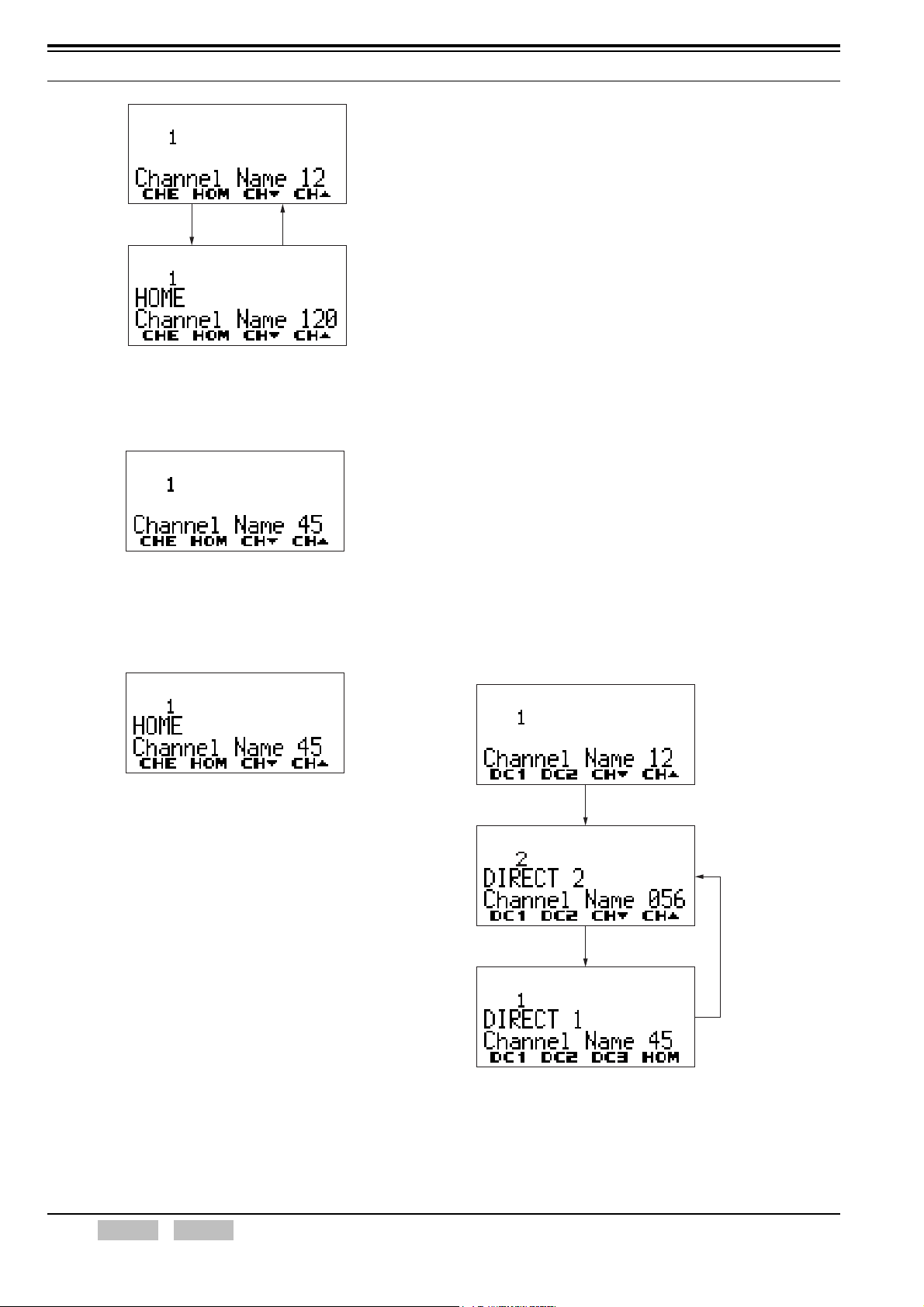
Transceiver Operation
z Jumping to the Home Channel:
1. Press the Home Channel key.
The transceiver jumps to the configured Home
Channel. The transceiver jumps to the previous
channel when the Home Channel key is pressed
again.
2.3.3 Operation after Selecting a New Channel
The transceiver pauses scanning when a channel is
changed during the scan. The transceiver resumes
scanning when conditions to make scan are satisfied.
The transceiver operation varies in the following ways.
FUNC (K)/Ver. 1.02 Confidential Contents Index 15
2 BASIC OPERATION
z Configuring the Home Channel Function (Refer to
FPRG 6.8 Key Assignment Window.)
z Configuring the Operator Selectable Home
Channel (Refer to FPRG 6.5 Zone/ Channel
Parameters Window.)
Press the
Home Channel key.
Press the
Home Channel key.
z Changing the Home Channel:
1. Select the channel to be configured as the Home
Channel.
2. Press and hold the Home Channel key for 3
seconds.
The current channel is configured as the Home
Channel.
2.5 Direct Channel
This function allows a user to jump to a frequently used
channel by pressing the PF key. When this function is
enabled, the user can jump a the frequently used channel
by pressing the PF key which has been assigned the
Direct Channel function. A maximum of 5 Direct
Channels can be configured in the transceiver.
The Direct Channel can be changed with the operation on
the transceiver if the Operator Selectable function is
enabled.
Assign the Direct Channel function to one of the PF keys
(Refer to 21 KEY ASSIGNMENT on page 113.)
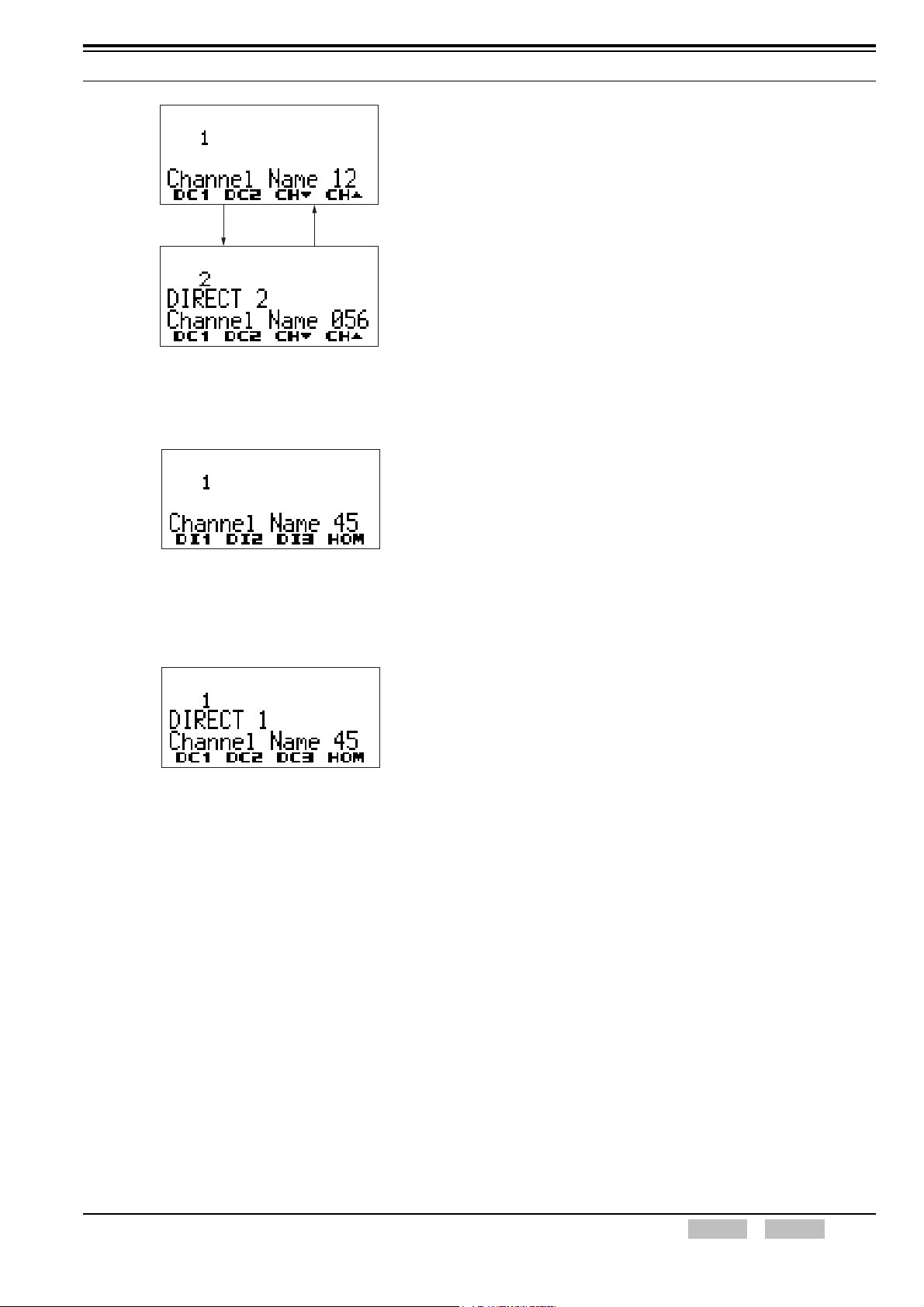
Transceiver Operation
z Jumping to the Direct Channel:
1. Press one of the Direct Channel 1 to Direct
Channel 5 keys.
The transceiver jumps to the configured Direct
Channel.
Note:
If the channel is changed with the Selector after the
transceiver jumps to the Home Channel by pressing
the Home Channel key, the previously selected
channel is configured as the Home Channel. In this
case, the transceiver jumps to the channel selected
using the Selector.
The transceiver pauses scanning on the selected
Home Channel and does not do the Lookback
operation when the Home Channel key is pressed
during scan. The transceiver does not resume
scanning until the PF key is pressed again. In this
case, the transceiver emits Alert Tone (Scan Stop
Tone (Normal)) every 5 seconds to notify a user that
scan is paused. The transceiver transmits using the
Home Channel and does not use the Revert
Channel while scanning pauses.
Configuration using KPG-95D
z Configuring the Home Channel to the Zone (Refer
to FPRG 6.5 Zone/ Channel Parameters Window.)
Press the
Direct Channel 2 key.
Press the
Direct Channel 1 key.
Press the
Direct Channel 2 key.
The transceiver returns to the previous channel
when the Direct Channel key is pressed again if
the Return function is configured for the Direct
Channel.
16 Index Contents Confidential FUNC (K)/Ver. 1.02
2 BASIC OPERATION
Configuration using KPG-95D
z Configuring the Direct Channel (Refer to FPRG
6.8.4 Direct Channel Tab.)
z Configuring the Direct Channel Function (Refer to
FPRG 6.8 Key Assignment Window.)
Press the
Direct Channel 2 key.
Press the
Direct Channel 2 key.
z Changing the Direct Channel:
1. Select the channel to be configured as the Direct
Channel.
2. Press and hold one of the Direct Channel 1 to
Direct Channel 5 keys for 3 seconds.
The current channel is configured as the Direct
Channel.
2.6 Communication
A user can select one of the following systems to
communicate with the TK-5210.
• Analog: The transceiver communicates using the
conventional FM Mode.
• P25: The transceiver communicates using the digital
modulation system compatible with APCO P25.
• Mixed Mode: The transceiver receives data with both
of Analog and P25 systems. The transceiver receives
data of both of Analog and P25 systems.
2.6.1 Receive
Analog:
The transceiver unmutes when the transceiver
receives the carrier. This occurs and the transceiver
emits the received audio signal if the received QT/
DQT matches with the configured QT/DQT Decode
code. (Refer to 7.1 QT/DQT Decode/ Encode on
page 36.)
Note:
The transceiver pauses scanning and jumps to the
selected Direct Channel when one of the Direct
Channel 1 to Direct Channel 5 keys is pressed
during the scan if the Return function is disabled.
The transceiver resumes scanning in conjunction
with the conditions of the target channel.
The transceiver transmits using the Home Channel
and does not use the Revert Channel while scan
pauses. The transceiver pauses scanning on the
selected Direct Channel and does not make the
Lookback operation when one of the Direct
Channel 1 to Direct Channel 5 keys is pressed
during the scan if the Return function is enabled.
The transceiver does not resume scanning until the
PF key is pressed again. In this case, the
transceiver emits Alert Tone (Scan Stop Tone
(Normal)) every 5 seconds to notify a user that scan
is paused.
If the Priority Type of scan is configured to Selected,
the Priority Channel is configured to Direct Channel
1 to Direct Channel 5.
If the Revert Channel is configured to Selected, the
Revert Channel is configured to Direct Channel 1 to
Direct Channel 5.
Note: Residual Audio Noise may not occasionally sound from
the transceiver when Squelch opens. This may occur
while the audio mute circuit is activated until the
transceiver receives audio signals after the transceiver
starts receiving.
P25:
z Squelch Type Configured to NAC:
The transceiver unmutes and emits the received
audio signal if the NAC matches.
z Squelch Type Configured to Selective Call:
If the NAC matches and Talkgroup ID or Individual
ID matches, the transceiver unmutes and emits the
received audio signal.
Mixed Mode:
The transceiver receives data with Analog or P25
depending on the received audio signal.
FUNC (K)/Ver. 1.02 Confidential Contents Index 17

2 BASIC OPERATION
Configuration using KPG-95D
z Configuring the Channel Type (Refer to FPRG 6.3
Personality Window.)
z Configuring the Analog Channel (Refer to FPRG
6.3.18 Analog Tab.)
z Configuring the P25 Channel (Refer to FPRG
6.3.19 P25 Tab (P25 Conventional).)
2.6.2 Transmission
Analog:
1. The transceiver transmits voice when speaking
into the microphone while pressing the PTT switch.
The transceiver continues sending the QT/DQT
while the PTT switch is pressed if the QT/DQT
encode code is configured. (Refer to 7.1 QT/DQT
Decode/ Encode on page 36.)
The Transmit LED lights red while the transceiver
is transmitting.
2. The transceiver stops transmitting when the PTT
switch is released and the transceiver returns to
standby mode.
2. The Talk Around function is enabled when the Tal k
Around key is pressed.
The “ ” icon appears on the display while the Talk
Around function is operating. (Refer to 1.6 Icons on
page 5.)
3. When the PTT switch is pressed, the transceiver
transmits on the receive frequency and the QT/DQT
decode code instead of on the transmit frequency and
the QT/DQT encode code.
Configuration using KPG-95D
z Configuring the Talk Around Function (Refer to
FPRG 6.8 Key Assignment Window.)
2.7 Transmit Power
Transmit Power is the transmission power of the
transceiver. This function allows a user to switch the
transmission power to High or Low.
Table 2-2 Transmit Power
P25:
1. The transceiver starts transmitting when the PTT
switch is pressed while the transceiver is in
standby mode.
The Transmit LED lights red while the transceiver
is transmitting.
2. The transceiver stops transmitting when the PTT
switch is released and the transceiver returns to
standby mode.
Configuration using KPG-95D
z Configuring the Channel Type (Refer to FPRG 6.3
Personality Window.)
z Configuring the Analog Channel (Refer to FPRG
6.3.18 Analog Tab.)
z Configuring the P25 Channel (Refer to FPRG
6.3.19 P25 Tab (P25 Conventional).)
2.6.3 Transmitting with the Talk Around Function
Assign the Talk Around function to one of the switches or
one of the PF keys. (Refer to 5 TALK AROUND
FUNCTION on page 34.)
1. Select the target channel for transmitting. (Refer to
2.3 Selecting a Channel on page 14.)
Configuration Transmit Power
High 5 W
Low 1 W
Select Low to reduce power when a repeater or the
receiving party is nearby.
High Transmit Power or Low Transmit Power can be
configured for each channel.
2.7.1 Changing the Transmit Power
Assign the Low Transmit Power function to a switch or
one of the PF keys. (Refer to 21 KEY ASSIGNMENT on
page 113.)
Transceiver Operation
1. Press the Low Transmit Power key.
The transceiver switches the Transmit Power from
High Transmit Power to Low Transmit Power. The
“ ” icon appears on the display.
Note:
The Key Beep A sounds when the transmit power is
switched from High Transmit Power to Low Transmit
Power and the Key Beep B sounds when the
transmit power is switched from Low Transmit
Power to High Transmit Power. (Refer to 1.8.1
Beep Tone on page 7.)
A user can switch the transmit power (High Transmit
Power or Low Transmit Power) using the Low
Transmit Power key only when the transceiver is
configured for High Transmit Power. The transmit
18 Index Contents Confidential FUNC (K)/Ver. 1.02
power cannot be switched to High Transmit Power
even if the Low Transmit Power key is pressed if
the transceiver is configured for Low Transmit
Power.
The status of the Transmit Power is stored even if
the transceiver is turned OFF. (Refer to 2.1.2
Turning the Transceiver OFF on page 11.)
2. Press the Low Transmit Power key again.
The transceiver switches the Transmit Power from
Low Transmit Power to High Transmit Power. The
“ ” icon appears on the display.
2 BASIC OPERATION
Mixed Mode:
Table 2-5 Channel Spacing (Mixed Mode)
Channel Spacing
Wide Narrow
25 kHz 12.5 kHz
Note: The transmit and receive frequencies of the configured
channel is configured to 25.0 kHz (Wide), 12.5 kHz
(Narrow) or 12.5 kHz (P25).
Configuration using KPG-95D
z Configuring the Transmit Power (Refer to FPRG
6.3 Personality Window.)
2.8 Channel Spacing
Frequency bandwidth is the width of frequency used for
communications. When the bandwidth is configured to
wide, the transceiver can transmit a larger amount of
information using a broader range of frequencies. A user
can select 25.0 kHz (Wide), 12.5 kHz (Narrow) or 12.5
kHz (P25) for each channel. Available bandwidth varies
depending on the modulation system. (Refer to 2.6
Communication on page 17.)
Analog:
Table 2-3 Channel Spacing (Analog)
Channel Spacing
Wide Narrow
25 kHz 12.5 kHz
P25:
Table 2-4 Channel Spacing (P25)
Channel Spacing
P25
12.5 kHz
Note: For P25, a narrower filter is used compared with the
receive filter used for Analog.
Configuration using KPG-95D
z Configuring the Transmit Bandwidth of the
Transceiver (Refer to FPRG 6.3 Personality
Window.)
2.9 Busy Channel Lockout
If a user transmits on a channel while other groups are
using the channel, the user may interfere with
communications. This function prevents such
interference.
With this function, the user can transmit without checking
the status of the channel.
Transmission can be disabled with the following 5
methods. The transceiver cannot transmit even if the
PTT switch is pressed while transmission is disabled with
the following functions. In this case, Warning Tone
beeps. Functions that can be configured vary depending
on the Channel Type. (Refer to 2.6 Communication on
page 17.)
• Carrier (Analog, P25)
The transceiver cannot transmit while receiving a
carrier. The transceiver can transmit when the
Monitor function is enabled. (Refer to 7.5 Monitor on
page 38.)
• Incorrect Tone (Analog)
The transceiver cannot transmit when the Signaling
does not match.
• Optional Signaling (Analog)
The transceiver cannot transmit until the Optional
Signaling matches. The transceiver can transmit
when the Optional Signaling matches.
• Incorrect NAC: (P25)
The transceiver cannot transmit when the NAC does
not match.
FUNC (K)/Ver. 1.02 Confidential Contents Index 19
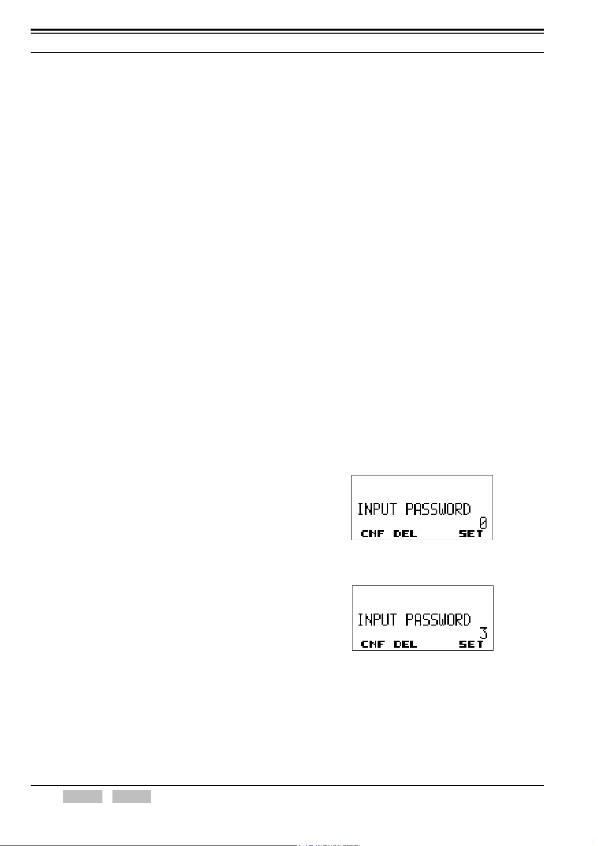
2 BASIC OPERATION
• Correct NAC: (P25)
The transceiver cannot transmit when the NAC
matches.
Note:
Warning Tone stops beeping when the PTT switch is released.
The Busy Channel Lockout function is used when the
transceiver transmits using the VOX function. (Refer to 11 VOX
(VOICE OPERATED TRANSMISSION) on page 54.)
The Busy Channel Lockout function is not used in the following
situations.
• Transceiver is in Emergency Mode.
• Transceiver transmits the Status ACK in FleetSync.
• Transceiver receives the Radio Monitor command.
Configuration using KPG-95D
z Configuring the Busy Channel Lockout function
(Refer to FPRG 6.3 Personality Window.)
2.10 BCL Override
This function allows the transceiver to transmit data while
transmission is restricted with the Busy Channel Lockout
function. This function is used for high priority
communications. (Refer to 2.9 Busy Channel Lockout on
page 19.)
A user can transmit by pressing or releasing the PTT
switch, and then pressing the switch again within 0.5
seconds even if the Busy Channel Lockout function is
enabled.
Configuration using KPG-95D
z Configuring the BCL Override function (Refer to
FPRG 6.2.1 Option Tab.)
2.11 Transceiver Password (K2- or K3-type only)
The Transceiver Password protects from the
unauthorized usage of the transceiver. This password
prevents the transceiver from being used by unauthorized
persons. A user cannot use the transceiver until the user
enters the correct password when the transceiver is
turned ON.
The Transceiver Password can be configured using KPG95D. The password can consist of a 6 numeric digits.
If no password is configured in the transceiver, the
transceiver can be used when the transceiver is ON. If a
password is configured in the transceiver, “INPUT
PASSWORD” appears on the display and the user is
required to enter the password.
The password can be entered with or without using the
12-key keypad.
Operation on the transceiver
z Entering the Password without using the
Keypad:
1. Turn the transceiver ON.
The “INPUT PASSWORD” appears on the display.
Transceiver Operation
1. Press the PTT switch.
Warning Tone beeps and the transceiver cannot
transmit.
2. Release the PTT switch, then press the switch
again within 0.5 seconds.
The transceiver starts transmitting.
Note:
The transceiver starts transmitting when the PTT
switch is released and the PTT switch is pressed
again within 5 seconds. In this case, the transceiver
emits Warning Tone until the switch is released.
The BCL Override function is enabled and
transmission becomes available when the PTT
switch is released and the switch is pressed again
in 0.5 seconds.
The BCL Override function is disabled if the
transceiver transmits using the VOX function.
(Refer to 11 VOX (VOICE OPERATED
TRANSMISSION) on page 54.)
2. Enter the first numeric digit by pressing the Side 2
or Side 3 key.
20 Index Contents Confidential FUNC (K)/Ver. 1.02
 Loading...