

Page 1
70%
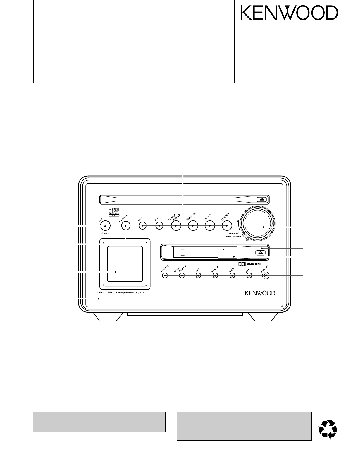
MICRO HiFi COMPONENT SYSTEM
RXD-M52-L
SERVICE MANUAL
(HM-532-L)
Althrough this service manual is described MD circuit
description, it is no concern with RXD-M52(deck version).
Knob
(K29-7769-03)
© 2000-6/B51-5639-00 (K/K) 3453
Knob
(K29-7772-14)
Indicator
(B12-0398-04)
Front glass
(B10-3606-03)
Dressing panel *
(A21-)
Knob
(K29-7773-04)
Escutcheon
(B07-2525-12)
Panel
(A29-1104-04)
Knob
(K29-7770-13)
In compliance with Federal Regulations, following are reproduction of labels on, or inside the product relating to laser
product safety.
* Refer to parts list on page 27.
KENWOOD-Crop. certifies this equipment conforms to DHHS
Regulations No.21 CFR 1040. 10, Chapter 1, subchapter J.
DANGER : Laser radiation when open and interlock defeated.
AVOID DIRECT EXPOSURE TO BEAM.
Page 2
(T90-0852-05)
(A70-1401-05): KMX.....RC-M0302
(A70-1403-05): TEH......RC-M0302E
Battery cover (A09-1161-08)
(E30-5828-05)
(T90-0858-05) (J02-0624-08)
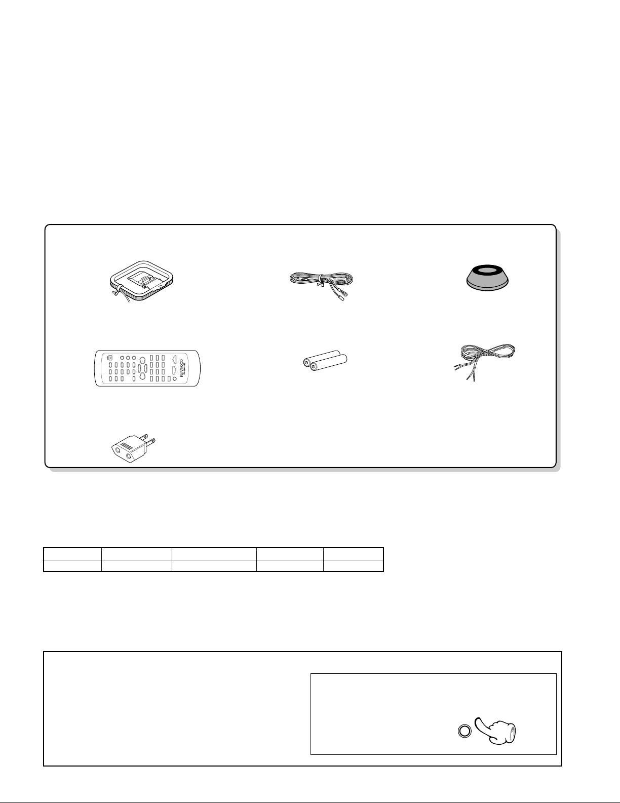
AM loop antenna (1)
Remote control unit (1)
Batteries (R6/AA) (2)
Feet for speaker (8)
Speaker cords(2)
FM indoor antenna (1)
* AC plug adaptor (1)
(E03-0115-05)
* Use to adapt the plug on the power cord to the shape of the wall outlet.
(Accessory only for regions where use is necessary)
RXD-M52
menu
/demo
CONTENTS / ACCESSORIES / CAUTIONS
Contents
CONTENTS / ACCESSORIES / CAUTIONS............. 2
EXTERNAL VIEW .......................................................3
CIRCUIT DESCRIPTION ............................................4
ADJUSTMENT ............................................................7
PARTS DESCRIPTIONS ............................................8
Accessories
PC BOARD ................................................................ 9
SCHEMATIC DIAGRAM .......................................... 13
EXPLODED VIEW ....................................................25
PARTS LIST..............................................................27
SPECIFICATIONS ......................................Back cover
System configuration
SYSTEM MAIN UNIT DESTINATION SPEAKER COLOR
HM-532-L RXD-M52-L KETMXH LS-M52-L BLUE
Cautions
Operation to reset
The microcomputer may fall into malfunction (impossibility
to operate, erroneous display, etc.) when the power cord is
unplugged while unit is ON or due to an external factor. In
this case, execute the following procedure to reset the
microcomputer and return it to normal condition.
• Please note that resetting the microcomputer clears the
contents stored in and it returns to condition when it left
the factory.
2
Unplug the power cord from the power outlet then, while
holding the menu/demo key depressed, plug the power
cord again.
Page 3
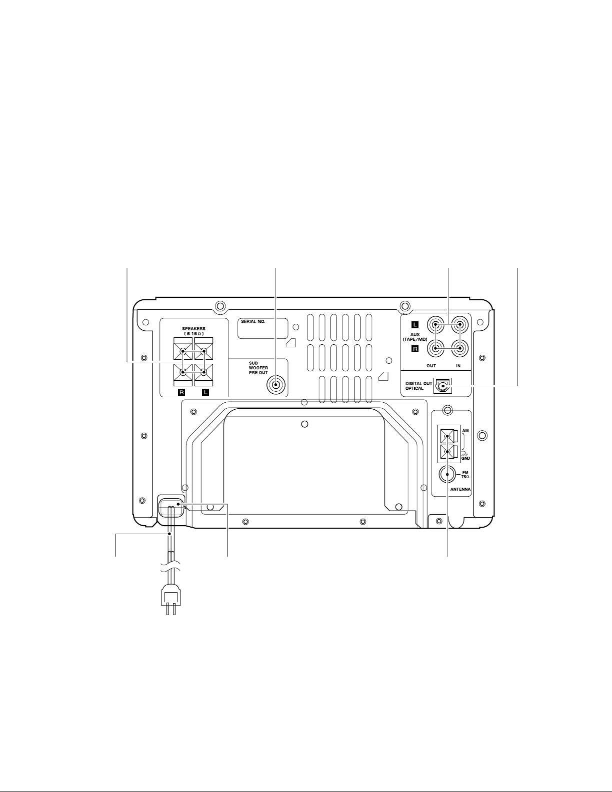
EXTERNAL VIEW
+
-
+
-
RXD-M52
Lock terminal board
(E70-0053-05)
Pin jack
(E63-0164-05)
Pin jack
(E63-1082-05)
Oscillating module
(W02-2732-05)
AC power cord *
(E30-)
AC power cord bushing
(J42-0083-05)
Lock terminal board
(E70-0127-05)
* Refer to parts list on page 27.
3
Page 4
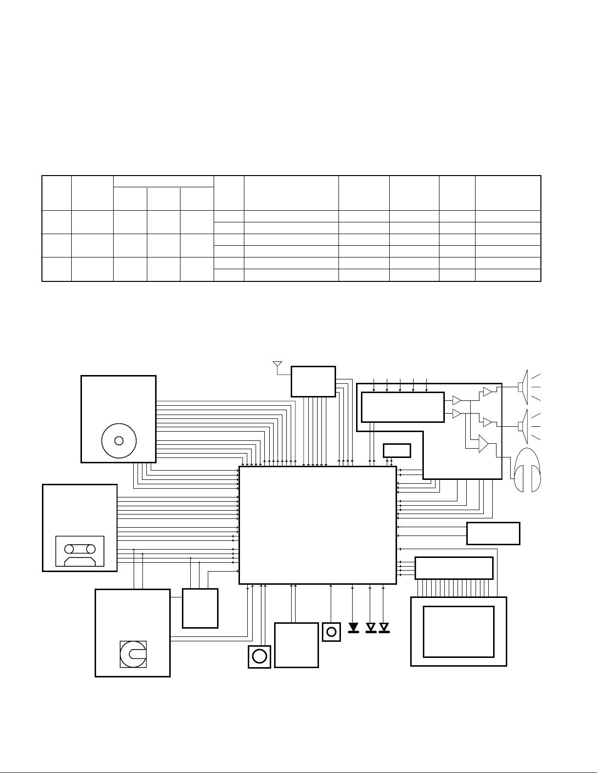
RXD-M52
CD mecha unit
CDM-34
DECK mecha unit
NJU3713D (IC4)
EXPANDER IC
X28
MDM-06
MD mecha unit
HD6432227N01FA
Back up
circuit
A/D
X29, IC1
M30624MG-304FP(DECK)
-303FP(MD)
SIO
SIO
PWM
Main uCOM
PWM
A/D
A/D
AMP hadrware
circuit
AMP_ system_IC
(input selecter)
TUNER unit
(RDS unit)
CD TAPE MD TUNER AUX
X29, IC8
A/D
A/D
A/D
INT
INT
RESET
EEPROM
INT
INT
UART
A/D A/D
encoder
REM
stnby
eject
cd md/ tape
Key matrix
(8keys X
2 lines)
LCD module
(64✽64dot)
LCD driver
RESET & CE
circuit
(mech ucom)
CIRCUIT DESCRIPTION
1. Initializing the CD/CASSETTE Receiver
1-1 Initialization Method
The CD/CASSETTE receiver will be initialized when you pressed [SOUND] key and turn the AC on.
1-2 Contents of Initialization
CD disc will be ejected from CD mechanism after initialized.
2. Conditions according to the Destination
( ) Port of Microprocessor
UNIT 3 2 1 BAND FREQUENCY IF RF EMPHASIS
DESTI-
NATION
K,P KI 0 0 0
ME1 0 0 1
E,T
E3
(RDS) AM 531kHz~ 1602kHz 9kHz +450kHz 9kHz 0
DESTINATION SW RECEIVING
(40Pin) (39Pin) (38Pin) RANGE
FM 87.5MHz~108.0MHz 100kHz +10.7MHz 25kHz 1
AM 530kHz~ 1700kHz 10kHz +450kHz 10kHz 0
FM 87.5MHz~108.0MHz 50kHz +10.7MHz 25kHz 0
AM 531kHz~ 1602kHz 9kHz +450kHz 9kHz 0
110
FM 87.5MHz~108.0MHz 50kHz +10.7MHz 25kHz 0
CHANNEL
SPACE
3. Microprocessor :M30624MG-303FP(MD version)
3-1 Microprocessor periphery block diagram
:M30624MG-304FP(DECK version)
4
Page 5
RXD-M52
CIRCUIT DESCRIPTION
3-2 Pin Description of Microprocessor
Pin No. Pin Name I/O Description
1 8SW2 I Detection port of 8cm disc for CD mechanism.
2 SCLK O Clock output to DSP IC(X29,IC9).
3 SENS I Sense input port from DSP IC(X29,IC9).
4 FAN/DA O Control port of fan motor.
5 DATA O Data output to DSP IC(X29,IC9).
6 XRST O Reset output to DSP IC(X29,IC9).
7 CLOK O Clock output to DSP IC(X29,IC9).
8 BYTE - Connected to ground.
9 CNVSS - Connected to ground.
10 XTIN I Clock input(32.768kHz).
11 XTOUT O Clock output(32.768kHz).
12 RESET I Reset signal input.
13 XOUT O Main clock output(1MHz).
14 VSS - Connected to ground.
15 XIN I Main clock input(1MHz).
16 VCC - Power supply.
17 NMI - Power supply.
18 u-COM CE I Detection port of AC off.
19 REM I Input port of remote control signal.
20 SCOR I Input port of sub code synchronized signal.
21 STBY RED O Standby LED(red) control terminal.
22 LCD BKLT O Control terminal of LCD back light.
23 STBY GR O Standby LED(green) control terminal.
24 LED CD O LED(CD) control terminal.
25 LED MD/TAPE O LED(MD/TAPE) control terminal.
26 CD XLAT O Latch output to DSP IC(X29,IC9).
27 ENC A I Input port of volume encoder.
28 ENC B I Input port of volume encoder.
29 MD RXD I Data input from MD mechanism microprocessor.
30 MD TXD O Transmission data output to MD mechanism microprocessor.
31 LCD SI O Data output to LCD driver.
32 LCD AO O AO control to LCD driver.
33 LCD SCL O Clock output to LCD driver.
34 LCD RST O Reset output to LCD driver.
35 SMK M/D I Discrimination port for deck and MD.
36 SQSO I Data input for CD sub Q data.
37 SQCK O Clock output for CD sub Q data.
38-40 SMK1-3 I Discrimination port of destination for TUNER.
41 STB O Strobe output to NJU3713D(X28,IC4).
42 W/R O Unused.
43 SDA I/O E2PROM data.
44 SCL O E2PROM clock output.
45 OP SW I Input port of open switch for deck(deck version only).
46 LCD CSI O CE output to LCD driver.
47 CL SW I Input port of close switch for deck(deck version only).
48 PH SW I Input port of photo sensor for deck(deck version only).
49 REC F SW I Deck forward switch input(deck version only).
50 HALF SW I Input port of half switch for deck(deck version only).
51 PLAY SW I Input port of play switch for deck(deck version only).
52 TYPE SW I Detection port for tape type(Normal/CrO2).
53 REC R SW I Deck reverse switch input(deck version only).
54 SBUSY - Unused.
55 SDATA - Unused.
56 RDS DATA I RDS data input(E/T type only).
57 TMUTE O TUNER muting control.
58 SD I Detection terminal of SD signal for TUNER.
59 ST I Detection terminal of stereo signal for TUNER.
60 PLL DATA O Data output to PLL IC.
61 PLL CLK O Clock output to PLL IC.
62 VCC - Power supply.
63 PLL CE O PLL chip enable.
64 VSS - Connected to ground.
65 PLL DO I PLL IF count input.
66 EMP/MONO O Control port of DE-emphasis.
5
Page 6
RXD-M52
CIRCUIT DESCRIPTION
Pin No. Pin Name I/O Description
67 AMUTE O Audio muting control.
68 SPRLY O Speaker relay control.
69 PWRRLY O Power relay control.
70 NC - Disconnected.
71 HPRLY O Relay control terminal for headphones.
72 HPDET I Detection terminal of headphones.
73 EVR CLK O Clock output to sound controller(X29,IC6).
74 EVR DATA O Data output to sound controller(X29,IC6).
75 RDS CLK I RDS clock input(E/T type only).
76 BACK CHK/ DECK SLT CL O
77 BACK ON/ DECK SLT OP O
78 MD RST/DECK CLK O Reset of MD mechanism and the clock of expander IC for deck.
79 MD CE/DECK DATA O CE of MD mechanism and the data of expander IC for deck.
80 MSTOP I Detection port of loading end for CD mechanism.
81 LD ON O Control port of laser on.
82 SPEED O Play back output port of hi-speed for CD.
83 DC OFF O Power control of system IC(X29,IC10) for CD.
84 LOAD OUT O Control port of loading out for CD mechanism.
85 LOAD IN O Control port of loading in for CD mechanism.
86 V/H O Control port of vertical and horizontal for CD. V/H version only
87 DINSW I Detection port of disc in for CD.
88 8SW1 I Detection port of 8cm disc for CD.
89 XY SW I Input port of sensor for vertical and horizontal. V/H version only
90 PROT I Detection port of current protection.
91 PROT TEMP I Detection port of temperature compensating for protection.
92 AIN LEVEL I Input port of audio signal.
93 BACKV I Input port of back up voltage for MD.
94 RDS SLEVEL I RDS signal level input(E/T type only).
95 KRO I Key return signal input.
96 AVSS - Connected to ground.
97 KR1 I Key return signal input.
98 AVREF - A/D,D/A reference voltage.
99 AVCC - A/D,D/A power supply.
100 12SW I Detection port of 12cm disc for CD.
Deck version only.
Detection port of back up voltage for MD mechanism. (MD version)
Control port of slot closing for deck. (Deck version)
Power on for MD mechanism. (MD version)
Control port of slot opening for deck.(Deck version)
4. CD Test Mode
4-1 Entering the Test Mode
To enter the test mode, press the CD [PLAY/PAUSE] key
and turn the AC on.
4-2 Cancelling the Test Mode
Turn the AC off.
4-3 Keys and Operation in the Test Mode
KEYS LCD OPERATION
CD CD TEST-03 Tracking servo off.
PLAY/PAUSE CD TEST-05 All servo on.
menu/demo –
sound
set
6
CD TEST-22 HI Hi speed (CD servo) when
CD TEST-22 Normal speed (CD servo) when
CD TEST-05
FB operation when servo on.
Sled in when servo off.
stop mode
stop mode.
FF operation when servo on.
Sled out when servo off.
5. Cassette Deck Test Mode
5-1 Entering the Test Mode
5-1-1 Tape Check Mode
• Turn the AC on with pressing the TAPE[PLAY] key.
5-1-2 Mechanism Check Mode
• Turn the AC on with pressing the TAPE[PLAY] and
[menu] keys simultaneously.
5-2 Cancelling the Test Mode
Turn the AC off
5-3 Keys and Operation in the Test Mode
TEST MODE KEYS OPERATION
DISPLAY
1Mecha.Test menu/demo Loading Test(Load in)
Mode sound Loading Test(Load out)
SLEEP Change-over the vertical and
(remote control) horizontal for LCD.
rec 4seconds recording
2Tape Check set Change-over the dolby on/off.
Mode
sound
Change-over the test mode
indication.
Change-over the beat cancel
on/off.
Page 7
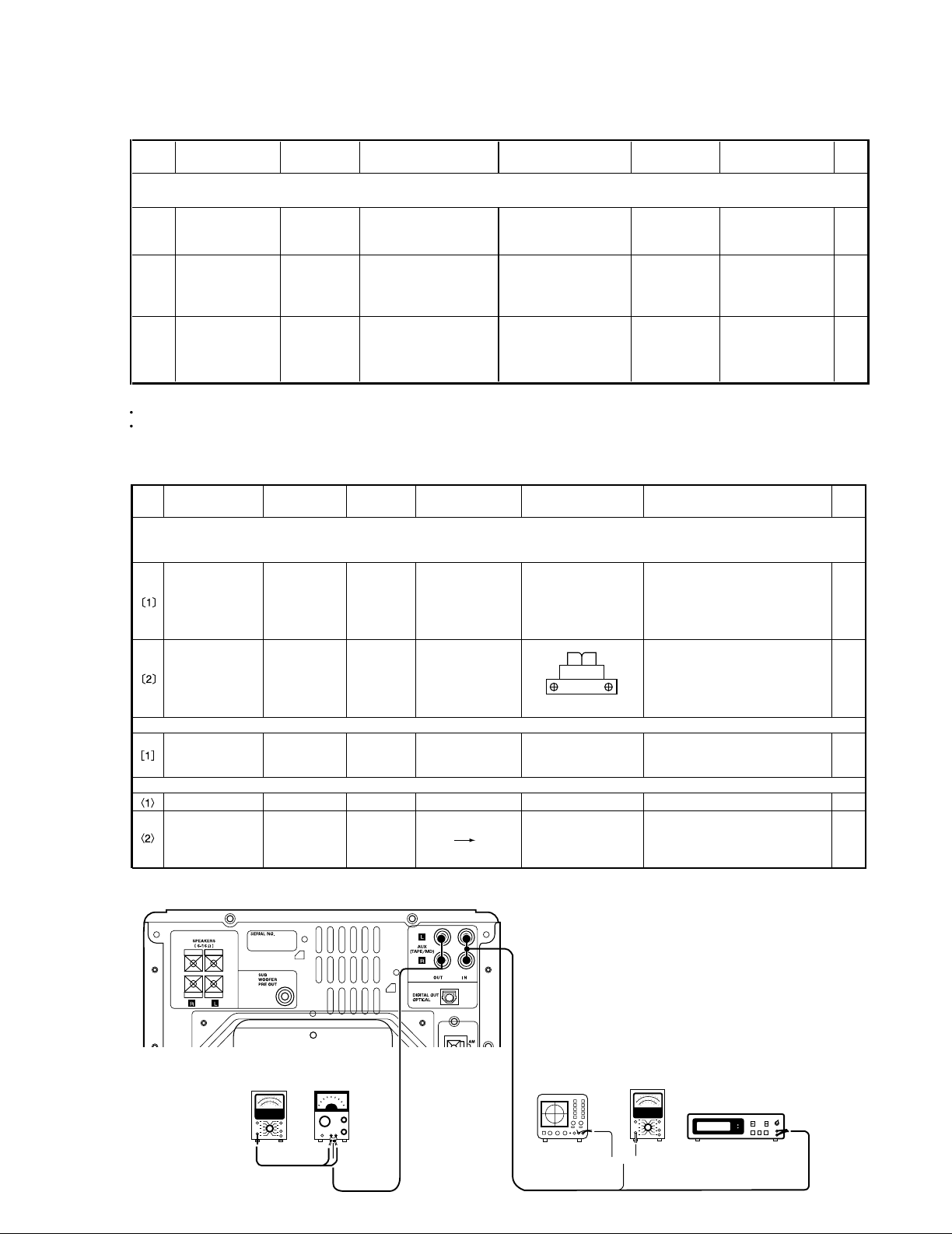
CD section
NO. ITEM
INPUT
SETTINGS
OUTPUT
SETTINGS
CD PLAYER
SETTINGS
ALIGNMENT ALIGN FOR FIG.
TEST MODE : While pressing the CD PLAY/PAUSE key, plug the power cord into the AC power wall output.
Load the TEST DISC.
[1]
LASER CURRENT
CHECK
Test disc
type 4
Connect the DC voltmeter
between 3 and 4 of CN4
on X29.
Press the PLAY/PAUSE
key to check that the
display is 03 or05.
—
50±20mA
[2]
FOCUS ERROR
BIAS
(Set up vertically)
Test disc
type 4
Connect an oscilloscope
as follows.
Press the PLAY/PAUSE
key . Confirm that the
display is 05.
FE BIAS
VR 1
(V/H version only)
Optimum eye pattern
[3]
FOCUS ERROR
BIAS
(Set up horizontally)
Test disc
type 4
Connect an oscilloscope
as follows.
CH1:RF(X29,CN4, 1)
GND:VC(X29,CN4, 2)
CH1:RF(X29,CN4, 1)
GND:VC(X29,CN4, 2)
Press the PLAY/PAUSE
key . Confirm that the
display is 05.
FE BIAS
VR 2
Optimum eye pattern
Note:
Type 4disc: SONY YEDS-18 Test Disc or equivalent.
Keep the step of adjustment.
+
-
+
-
CASSETTE DECK
NO. ITEM
INPUT
SETTINGS
OUTPUT
SETTINGS
CASSETTE DECK
SETTINGS
ALIGNMENT ALIGN FOR FIG.
Unless otherwise specified, set the respective switches as follows:
TAPE: NORMAL INPUT: AUX IN OUTPUT: AUX OUT 0dBm=0.775V
ø. Cassette mechanism (REC/PB head adjustment)
Demagnetization
and cleaning
——
(POWER OFF)
demagnetization
(PLAY)
cleaning
REC/PB head
erase head
capstan
pinch roller
Demagnetize the REC/PB head by
head eraser. Clean the REC/PB head
,eraser head, capstan and pinch
roller with a cotton swab immersed
in alcohol.
REC/PB head
azimuth
TCC-153
MTT-114
10kHz,-10dB
(B) PLAY
Adjust the output to maximum and
adjust the azimuth adjustment
screw for the Lissajous waveform
pattern of the oscilloscope to
become close to a 45ß straight line.
¿. Capstan motor adjustment
Tape speed
(NORMAL)
TCC-110
MTT-111
3kHz
(B) PLAY
VR.
inside motor
Adjust so that the frequency 3kHz
at the center of the tape.
¡. PC board adjustment
Playback level TCC-130 (B) PLAY
VR1(Lch),VR2(Rch)
-2.5dBm
(B) REC PLAY
Bias current
TCC-108
12.5kHz
-24dBm
(A)
VR3(Lch)
VR4(Rch)
-24dBm
Measurement equipment connection
FWD
RVS
{
(A) (B)
AC voltmeter AC voltmeter
Oscilloscope
Distortion meter
AG
ADJUSTMENT
RXD-M52
7
Page 8
RXD-M52
PARTS DESCRIPTIONS
8
Page 9

R37
R119
R128
R130
R122
R118
R121
R38
C111
R25
R24
C108
C110
C107
C106
R129
W309
R235
R229
R223
R237
R239
R236
R203
R209
R208
R132
R131
R133
R210
R218
R220
R222
R221
R212
R211
R213
R214
R9
R19
R21
C112
R10
R22
C114
C113
R20
R15
R18
R17
R23
R16
W308
R116
R117
C9C10
R108
R101
R102
R227
R228
R232
R233
R2
R3
R1
R4
R5
R6
C1
C2
R271
R270
R33
R103
R104
R105
R106
R107
R31
C30
R32
R219
R238
R215
R216
R217
R12
W301
W306
W305
R262
R272
R273
R231
R11
R135
R136
R261
W310
R234
R8
R7
C13
C14
C109
C102
C101
C16
C15
C104
C4
C12
C11
C223
C20
C228
C3
C224
C236
C29
C115
R225
C217
C23
C21
C22
C24
C232
R240
C25
R126
R241
C116
C27
C26
C28
8
1
4
5
TH1
EB
E
B
EB
EB
EB
EB EB
EB
EB
EB
EB
C257
C256
R250
R255
BE
R254
R252
C255
R251
R253
4
3
1
5
C254
R124
R115
R123
C18
C17
C105
R114
R113
R112
R111
R110
R109
R125
D39
Q5
Q6
Q105
D40
D31
D32
D24
D20
D21
Q8
Q2
Q1
Q10
Q11
D28
Q103
D15
D115
D41
IC4
D19
Q7
Q101
D26
Q13
IC7
D4
W40
R224
W66
W73
W33
W30
W91
W29
W38
W78
W79
W71
W48
W4
W76
W16
W14
W59
W64
W69
W70
W72
W52
W68
W65
W58
W12
W83
W18
W56
W27
W41
W86
W46
W50
W17
W15
W60
W2
W77
W21
W20
W5
W3
W31
W8
W1
W9
W11
W43
W51
W67
W36
W26
W37
W23
W22
W63
W62
W28
W25
W35
W85
W32
W34
W53
W55
W7
W49
W19
W89
W87
W47
W42
W74
W45
W54
SKIP
DOWN
TUNER
STOP
CD
EJECT
UP
SKIP
MD
CD
1
+7V AVR.
+9V
AVR.
AVR.
POWER AMP
I.PROTECTION
MUTE DRIVE.
FAN
DRIVE.
LCD CONT.
+10V AVR.
POWER
R204
R205
R201
R206
R120
W10
C225
C258
C221
C6
C5
C229
C205
C103
W13
W207
W210
W211
W208
W209
W212
W213
C31
C202
R259
C201
C241
R28
R27
R29
R30
R13
R14
C227
K2
K3
C8
C32
C203
C204
C238
W6
R134
R127
C208
W61
C206
C216
C218
C19
C213
C214
C219
C222
W44
C237
C212
C209
C210
R230
R207
W57
W24
C7
W201
W202
-10V
1
6
1
2
4
5
7
1
IO
G
GIO
5
1
1
2
1
2
4
5
1
13
15
1
14
15
2
1
BE
2
1
12
13
1
5
4
2
10
11
2
1
16
17
W75
2
F1
R258
1
2
1
K1
2
F.OFF
R256
W90
C252
R249
6
C253
1
T1
W80
C251
+5.1V AVR.
R257
MD EJECT
W39
1
5
H.P.
P4
REC AUX
1
2
4
5
ENTER
SET
DISPLAY
MENU
B
E
B
E
B
E
BE
EB
E
B
E
B
WH5
WH2
X07-3220-10 A/5 (J70-1422-11)
X07 E/5
X07 D/5
X07 C/5
X07 B/5
D34
D30
D33
D29
D27
Q3
Q4
CN8
Q9
D108
D107
CN14
D23
IC3
Q102
S8
S2
S3
S4
S6
S1
S7
S5
A2
E2
CN9
D101
Q15
CN7
D25
CN6
J2
A1
J1
D3
D1
P1
CN3
IC6
IC1
D109
Q14
DIGITAL IN
SUPER
WOOFER
PRE OUT
L
SPEAKERS
R
OPTICAL
CN5
CN4
IC5
WH4
D113
D110
D112
IC2
D2
CN15
D106
D114
E6
S16
P3
CN2
CN16
CN17
CN1
D6
D13
D5
D37
D8
D7
Q12
D10
E1
WH1
D11
D12
D102
S15
Q104
WH5
E4
WH3
PHONES
J4
D36
D35
S14 S13
E5
WH2
E3
S12 S11
D103
S10 S9
D104
A BDFHJCEG I
PC BOARD (Component side view)
1
2
3
4
5
6
7
Refer to the schematic diagram for the value of resistors and capacitors.
109
Page 10

KMOQSLNPRT
R91
R286
C158
C110
C109
C34
R104
R105
R110
R111
R77
C8
R76
R103
R101
R102
R125
R126
R124
R122
R123
R129
R127
R128
R115
R116
R114
R112
R120
R121
R119
R117
R118
R45
R46
R44
R43
R51
R47
R48
R35
R36
R34
R32
R33
R40
R41
R39
R65
R66
R63
R67
R68
R55
R56
R54
R52
R53
R60
R59
R57
R58
R231
R232
R283
R223
R213
R214
R211
R212
R215
R221
R222
R216
R217
W22
R301
R302
R303
R306
R304
R305
C7
R147
C9
R148
R258
R138
R139
R153
R188
R201
R186
R185
R202
R203
R204
R187
C160
C164
R154
R183
R184
R181
R182
C188
C182
C58
C65
C59
C64
C61
C187
C208
C120
C147
C148
C119
C118
C207
C243
C53
C117
C57
C69
C104
C115
C102
C103
C126 C125
C116
C131
C134
C133
C132
C68
C66
C67
C75
C74
C101
C152
C14
C16
C15
C33
C32
C50
C31
C22
C21
C23
W6
R14
R15
R11
R12
C10
R1
C12
R18
R2
W4
R16
W3
W5
C40
R26
R25
C39
R259
C130
C129
C127
C128
L5
C11
C63
W21
C174
C177
C175
C194
R161
R255
L6
L8
C226
C84
R261
R262
C153
C78
R251
R252
W13
W8
R172
R171
C46
C45
W14
C26
C105
C193
W1
C244
C146
C49
W31
R162
C176
C178
C232
R315
C231
R316
R241
R106
C172
C156
C157
C155
C235
W12
C236
C167
C210
C209
C28
C82
R253
R254
C224
C85
C225
C192
R190
R189
C25
C20
C227
C165
R317
R318
R320
R319
R49
R72
R64
R70
R71
R69
R8
R140
R141
R158
R152
R166
R165
R80
W7
R82
R81
R157
R13
C191
R313
R17
C251
C71
5
8
1
4
1
8
5
4
80
1
20
21
40
41
60
61
20
11
10
1
E
B
EB
E
BEB
EB
SG
D
SG
D
SG
D
EB
EB
EB
EB
EB
EB
EB
EB
EB
E
B
EB
EB
E
B
IC8
Q13
Q12
Q17
Q18
Q19
Q14
Q15
Q16
Q3
Q1
Q24
Q23
Q25
Q4
Q7
D22
D4
D2
D1
IC7
D26
IC15
D3
Q29
D25
Q30
Q6
IC9
Q22
Q20
Q21
D24
D10
Lch
IN
OUT
IN
Rch
OUT
JIGU
C81
R207
R78
C150
C72
C149
C201
C185
C205
C202
C163
C181
C171
C113
C124
C123
C114
C135
C139
C136
C143
C42
C1
C41
C3
C52
C154
C55
C35
C36
C27
C24
C2
C56
C212
X1
C140
C145
C144
R85
C76
C51
R233
R234
C169
VR2
VR1
C151
C166
R167
3
1
EB
X3
for
4
2
1
5
1
5
4
2
O
G
I
12
13
2
1
L7
L2
1
25
2
26
14
31
30
2
1
13 1 1 13
212
1
2
11
10
X2
X4
R151
C108
C107
C111
C106
C137
R107
R108
R10
R74
R73
R130
R131
R37
R38
R62
R61
R282
R281
R312
R309
R310
C4
C5
R308
R285
R307
R145
R146
R143
R144
R150
R149
R142
R137
R205
R206
C186
C62
C183
C184
C43
C77
C142
C70
C73
C237
C18
R19
C17
C238
C37
R20
R9
R7
R30
R31
R29
R27
R28
R22
R21
C38
R23
R24
C83
L4
C60
L1
R159
R257
C6
R194
R192
R191
R176
R175
R174
R173
R177
R178
R179
W11
R160
R180
C213
R242
R239
R42
R79
W2
R1
C141
C138
C19
R197
R198
C161
R238
R164
R311
C204
C203
R10
R321
R325
R243
R244
R326
R324
R323
C13
C241
C211
C112
C173
R256
C91
R113
R314
R156
R195
R196
E
B
B
E
B
E
R193
R75
1
21
22
42
1
100
81
80
51
50
31
30
1
8
9
16
54
28
27
1
4
1
8
5
1
8
4
5
IGO
4
1
1
13
1
15
1
13
S1
Q28
J2
IC2
J1
CN3
CN5
CN6
CN7
CN9
CN4
CN8
CN2
CN1
IC14
X29-2700-00 (J70-1405-11)
TUNER
SYSTEM CONTROLLER
CD DRIVER
SELECTOR & VOLUME
A1
IC3
IC4
MD I/O AMP.
IC5
CD DSP & DAC
E1
Q11
Q2
Q10
D21
IC11
D12
IC12
IC1
IC6
IC10
IC13
R
L
AUX
AM
GND
FM
R98
C23
R22
R33
R20
R32
R35
C20
C19
R18
R17
C35
C47
R38
C24
R37
R41
R42
R301
R302
R83
R82
R88
R78
R81
R85
R86
C50
R68
R84
R80
R76
R45
R24
C42
R46
C45
R44
R53
R52
R55
C48
C58
C46
R49
R50
R19
R23
R21
C31
R31
R39
R40
R10
R9
R77
C36
R75
C14
R8
R7
R5
R6
C68
C57
R69
R57
R60 R70
C53
R72
R71
C54
C67
C51
R56
R87
R79
R16
C5
R15
C6
R13
R14
R26
R25
R29
R30
R28
R27
C55
R11
R93
R90
R91
R1
R2
C40
C39
R4
R3
R92
R97
R96
R95
R94
C13
C41
C32
C60
C52
EB
EB
EB EB
EB
EBEB
EB
EB
EB
EB
EB
EB
Q5
Q4
Q8
Q6
Q16
Q10
D1
Q18
Q23
Q15
D2
Q17
D5
Q11
Q21
Q22
D6
D7
Lch
Rch
11
1
W22
W14
W18
W10
W23
W28
W25
W5
W15
W13
W32
W31
W17
W19
W40
W37
W7
W8
W30
W12
W6
W20
W21
W16
W24
W36
W26
W27
W29
W34
W33
W42
W41
W2
W9
W39
W35
W11
W38
W3
W4
W1
DOLBY IC
BIAS
EX IC
MECHA CONT.
PB LEVEL
PB & REC EQ IC
OSC
BIAS
Lch
Rch
R54
R47
R48
L6
C34
C44
C49
C33
R43
C43
C301
C37C38
R36
C59
L1
L2
C22
C21
C27
L5
R51
C28
C30
L4
L3
C11
C3
C12
VR2
VR1
C66
C9
C10
C29
C25
C26
C18
C8
C7
R12
C15
C4
C16
C17
W46
VR3
VR4
1
9
1
7
1
11
12
22
5
1
13
1
1
212
13
1
13
1
5
10
9
9
18
1
1
18
916
E
E
B
B
E
B
B
B
EEB
E
E
B
E
B
WH1
IC4
Q12
Q1
Q2
CN3
E1
CN1
IC1
Q13
Q14
Q7
Q9
IC5
CN5
Q3
IC3
X28-3050-10 (J70-1407-01)
CN4
CN2
IC2
D3
D4
E3
E2
PC BOARD(Component side view
1
2
3
4
)
5
6
7
Refer to the schematic diagram for the value of resistors and capacitors.
11 12
Page 11

A BDFHJCEG I
22
21
20
19
18
17
16
15
14
13
12
RIN-L
RIN-R
B-1/2
A/B
A-N/C
PNF-L
PEQ-L
OUT-L
OUT-R
PEQ-R
PNF-R
1
2
3
4
5
6
7
8
9
10
11
VCC
ROUT-R
ROUT-L
REC-RET
B-IN-L
B-IN-R
VREF
A-IN-R
A-IN-L
IREF
GND
16151413121110
9
R
GND
R
BIAS
R-P
RRR
1
2
3
4
5
6
7
8
L
VCCLV-REF
DOLBYLL
L
1
2
345
678
9
IN2
VCC
OUT2NCGNDVSOUT1
VREF
IN1
18
17
16
15
14
13
12
11
10
VDD
REC EQ.
A/B1
A/B2
PLAY EQ.
CLR
STB
CLK
DATA
1
2
3
4
5
6
7
8
9
REC/PLAY
DOLBY
BEAT
BIAS2
VSS
BIAS1
MUTE
CPM
SOL
7
6
5
4
3
2
1
L-PLAY
L-REC
GND
R-REC
R-PLAY
GND
ERASE
5
4
3
2
1
MOTOR(CCW)
MOTOR(CW)
GND
OPEN SW
CLOSE SW
1
2
3
4
5
6
7
8
9
10
11
12
13
R REC SW
CrO2 SW
PLAY SW
COM(GND)
CPM(12V)
GND
PACK SW
SOL(12V)
PHOTO
F REC SW
REC-R
PLAY-R
GND
REC-L
PLAY-L
13
12
11
10
9
8
7
6
5
4
3
2
1
PLAY Rch
REC Rch
GND(ANALOG)
REC Lch
PLAY Lch
+12V(ANALOG)
GND(BIAS)
+12V(BIAS)
GND(MECHA)
+12V(MECHA)
GND(LOADING)
+7V(LOADING)_
NC
13
12
11
10
9
8
7
6
5
4
3
2
1
DATA
CLK
R-REC-SW
CrO2-SW
PLAY-SW
PACK-SW
F-REC-SW
PHOTO
CLOSE-SW
OPEN-SW
OPEN
CLOSE
STB
REC-IN
PLAY-IN
REC-OUT
DETECT
PLAY-OUT
10K
2.2K
SENSOR
SOLENOID
1
4
2
3
6
5
2
1
3
4
5
1
2
3
4
5
7
6
9
8
10
11
13
12
150K
R37
680P
C35
680P
C36
150K
R38
10mH
L2
220P
C40
15K
R42
10u16
+
C38
10K
R40
10K
R39
L1
R41
15K
220P
C39
10mH
10u16
+
C37
1K
1K
22K
330u10
+
C33
10K
R55
0.22
C50
22uH
L6
820
R54
2K
R53
4
6
36K
R52
3.3u50
C49
+
10
R51
1/4W
1/4W
5600P
C47
27K
R50
5600P
C46
27K
R49
0.01
C45
R48
3.3
R47
1/4W1/4W
3.3
L5
16
34
52
10u16
+
C44
6800P
C43
1K
R35
+
100u16
C34
47P
C31
47P
C32
270
R18
180K
R20
15K
R24
20K
R22
0.01
C24
1.5K
R16
4.7u50
+
C22
3900P
C20
10K
R14
4.7u35
+
C10
4.7u50+1.5K
+
C19
3900P
C21 R15
C9
4.7u35
R13
10K
180K
C23
0.01
20K
R21
R23
15K
R19
R17
270
15
14
17
22u16
+
C18
7.5K
R26
1u50
C28
+
2.2u50
+
C30
1.8K
R30
2.4K
R28
10u35
+
C26
1u50
C27
2.2u50
+
C29
R29
1.8K
+
R27
2.4K
C25
10u357.5K
R25
+
6
1
2
34
34
2
16
3.9K3.9K
R10
6800P
C14
6800P
2.2u50
+
27K 10u16
+
+
2.2u50
C12
27K
R6
+
10u16
C16
1.6K1.6K
R8
C15R5
C13
R9
C11
R7
R12 10 1/4W
C17 47u25
+
C8 1u50
+
C7 22u16
+
4.7u50
+
C4
100
R2
100K
R4
+
4.7u50
C3
100
R1
100K
R3
C6 0.22 0.22
18K
220P
C42
33K
R46
220K
VR4
220P
C41
33K
R45
VR3
220K
10
R43
1/4W
1000P
C56
0.01
C57
100
R71
100
R72
R84 10K
R85 10K
R80 10K
REC SW
REC SW
P/B SW
CONT
P/B SW
7
3
1
G
2
5
GND
4
VCC
6
G
9
8
+
10u16
C59
10K
R44
6
10K
R79
R86 22K
5.6K
R87
47K
R78
4.7K
R76
R75
4.7K
R77
47K
R81 10K
R82 10K
R83 10K
R88 10K
IC2
L3
L4
R93 1K
R92 1K
R96 1K
R97 1K
R57 10K
R91 1K
R70 3.9K
R60 9.1K
R90 1K
R98 100
C60 220P
R69 100
C55 220P
C54 220P
R68 100
0.1
C51
1
C52
270
R56
+B
3
9
8
9
8
6
4
3
1
1
IC1
R33
R31
R32
C5
R11
+12V+12V
+12V
+12V+12V+12V
+12V
+12V+12V
+12V+12V
+12V +12V
+12V
+12V
+12V
+12V
+12V
+12V+12V
BIASBIAS
BIAS
BIAS
+12V+12V+12V
+12V
+12V
+12V +12V
+12V
+12V
+12V
+7V
+7V
+7V+7V
+5V
+5V+5V
+5V+5V
+5V
+7V
+7V
+5V
+5V
+5V
+5V+5V
+5V
3
5
1
2
14
15
17
1
2
4
2
1
3
6
5
7
11
9
8
10
12
13
1
13
12
11
10
9
8
7
5
4
2
5
10
R36
1/4W
NC
NC
NC
0.01
C48
0.01
C53
+12V
5
4
3
2
1
10K
VR1VR2
10K
IC1
IC2
IC5
IC4
IC3
B
C
(X28-3050-10)
RXD-M52 (1/3)
CN5
CN3
CN4
E1
CN2
REC-R
HALF
CrO2
REC-F
CAPSTAN
MOTOR
MODE SW
OPEN SW
CLOSE SW
MOTOR
LOADING
MECHANISM ASS’Y D40-1673-05
R/P/E HEAD (PCB)
Lch
Rch
ERASE
R/P HEAD
HEAD
Q17
Q18
R/P
SW
D2
Q3
Q4 Q5 Q6
BIAS
AVR
BIAS
OSC
Q1
Q2
E3
P.B REC
EQ
Lch
Rch
DOLBY B TYPE
NR SYSTEM
BIAS
(L)
MOTOR
CONTROLLER
SW
HEAD
PLAY/REC
Q11
Q9
Q10
SOLENOID
DRIVER
D3
Q7
D4
Q8
CAPSTAN
DRIVER
D5
Q12
+5.0V AVR
TEST PIN
2/3
CN8
X29-
2/3
CN9
X29-
B LINE
GND LINE
SIGNAL LINE
RECORDING LINE
IC1 : HA12219NT
IC2 : HA12136A
IC3 : BA3126N
IC4 : NJU3713D
IC5 : TA8409S
Q1,2,12 : 2SC1740S(Q,R) or
2SC2458(Y,GR)
Q3 : 2SC3940A(R,S) or
2SD863(F,E)
Q4-6,8,10,18 : DTC124EUA or
UN5212
Q7,9 : 2SA1286-T11
Q11 : 2SC4081(R,S) or
2SC4116(Y,GR)
Q17 : DTA124EUA or
UN5112
D1,5 : UDZ5.6B
D2 : MA111
D3,4 : 1SS133 or
HSS104A
D1
PB LEVEL
WH1
BAIS
(R)
EXPANDER IC
5.7V
5.7V
11.9V
12.0V
PLAY : 6.0V
REC : 11.9V
PLAY : 11.9V
REC : 0V
PLAY : 0V
REC : 4.7V
4.6V
4.9V
7.1V
4.9V
4.6V
LOADING
OUT : 5.3VIN : 5.3V
LOADING
4.9V
12.1V
12.0V
11.4V
4.9V
REC : 6.7V
REC : 7.0V REC : 11.9V
7.7V
CrO2 : 11.4V
Nor : 0V
CrO2 : 0V
Nor : 4.7V
REC : 4.7V
12.0V
11.8V
5.7V
5.7V
5.7V
5.7V
5.7V
5.7V
5.7V
5.7V
1.3V
5.6V
5.6V
CrO2 : 4.9V
Nor : 0V
PLAY : 0V
REC : 4.8V
Nor : 0V
CrO2 : 4.9V
5.7V
: 5.8V
REC
: 8.7V
PLAY
5.7V
5.8V
5.8V
REC
:0V
: 4.7V
PLAY
0.9V
5.7V
5.8V
1.3V
5.8V
1.3V
5.8V
5.6V
5.8V
11.9V
5.8V
12.0V
12.0V
12.1V
7.1V
5.6V
REC : 4.9V
PLAY : 0V
4.9V
Nor : 4.9V
CrO2 : 0V
REC : 4.9V
PLAY : 0V
: 4.9V
PLAY/REC
PLAY : 0V
REC : 4.9V
Nor : 0V
CrO2 : 4.9V
4.9V
1
2
3
4
5
6
7
CAUTION: For continued safety, replace safety critical
components only with manufacturer's recommended parts
(refer to parts list). indicates safety critical components.
For continued protection against risk of fire, replace only
with same type and rating fuse(s). To reduce the risk of
electric shock, leakage-current or resistance measurements shall be carried out (exposed parts are acceptably
insulated from the supply circuit) before the appliance is
returned to the customer.
The DC voltage is an actual reading measured with a
high impedance type voltmeter. The measurement value
may vary depending on the measuring instruments used
or on the product. Refer to the voltage during RECORDABLE MD PLAY unless otherwise specified; The value
shown in ( ) is the voltage measured at the moment of
STOP. The voltage followed by (REC) refers to the value
during MD RECORDING.
Y39-3560-10
RXD-M52
Page 12

KMOQSLNPRT
IC8
(X29-270X-XX)
SW PCB (X29-2660-00)
CD MECHANISM (D40-1674-05) / CDM-34(B)
TRAVERSE UNIT (D40-1639-05)
PICKUP
C
A
B
A1
CN3
AUX IN 3
AUX OUT 4
Lch
AUX OUT 2
AUX IN 1
Rch
FM75
AM ANT
J2
GND
J1
Q10
D21
CN4
LD
ON/OFF
Q12
Q11
RF AMP
Q16
Q17
Q19
Q18
CD FOCUS BIAS
V/H CHANGE-OVER
FE BIAS
(VERTICAL)
FE BIAS
(HORIZONTAL)
CD DISC
SENSOR
LOAD
DISC SENSOR
E1
D24
B LINE
B LINE
GND LINE
SIGNAL LINE
RECORDING LINE
B
A
PD
E
C
D
F
LD
SLED MOTOR
STL SW
DISC MOTOR
Q1
D1
Q4
D4
Q2
D2 D3
Q3
(H: DISC
DETECTOR
8cm DISC
(H: DISC
DETECTOR
12cm DISC DISC IN
EXSIT)
(L: DISC
EXSIT)EXSIT)
S1
POSITION
DETECT
LOADING
STOP
LOADING
MOTOR
M
M
CN4
CN2
CN3
CN1
IC1 :
IC2 : S-80840ANY
IC3 :
IC4 :
IC5 : uPC2905HF or
IC6 : M62498AFP
IC7,11,13 : NJM2100M
IC8 : CXA1821M
IC9 : CXD3017Q
IC10 : BA5801FS
IC12 : BU1923F
IC14 : TA79005SB
Q1,4 : 2SC4081(R,S) or
2SC4116(Y,GR)
Q2,16-19 : 2SA1576A(R,S) or
2SA1586(Y,GR)
Q3,7,11 : UN5112 or
DTA124EUA
Q6,15 : UN5212 or
DTC124EUA
Q10 : 2SA1577(Q,R)
Q12 : UN5216 or
DTC143TUA
Q13 : 2SC4213(B)
Q20-22 : 2SK2158
Q28 : 2SB1640
D1,4,21,22,26 : MA111
D2 : 1SS402
D3 : UDZ3.9B
D10 : DAN202U
D12 : UDZ5.1B
D24 : DA204U
RXD-M52-L (X29-270X-XX)
RD-VH5MD-L/S (X29-2702-71)
RD-M72MD (X29-2702-72)
RD-VH5MD-L/W/S (X29-2700-00)
RD-IT2000MD-R (X29-2700-01)
TUNER PACK (AM/FM)
CD RF3T
CHANGE-OVER
LM2940CT-5.0
Q29,30 DTC143TUA or:
UN5216
D25 : UDZ2.7B
M
2/4
X28CN2
1/4
CN1
X33-
2/4
X28E1
20
19
18
17
16
15
14
13
12
11
VCC
L DON
LC/PD
RFE
RFO
FE
FE-BIAS
TE
VC
EO
1
2
3
4
5
6
7
8
9
10
LD
PD
A
B
C
D
VEE
F
E
EI
PLL CE
S LEVEL
11
13
12
3
1
2
4
GND
AM IN
FM DET
SD(TUNED)
4
365
8
7
10
9
Lch
ST(STEREO)
Rch
GND
+9V
PLL DATA
PLL CLK2DE-EMPH/MONO
1
PLL DO
BSW2
12SW
BSW1
D IN SW
M STOP
SW 5V
SW GND
LOD+
LOD-
SLD-
SLD+
SLT SW
DM+
DM-
FCS-
TRK-
TRK+
FCS-
GND
D
B
C
A
LD
PD
VR
VC
VCC
F
E
220K100K220K 100K
100
100
C103C101
R187
220P
R181
220P
R185
R183
1K
C102 C104
220P
R182
220P
R186
R184
1K
R188
W21
59
58
94
4
65
636160
66
L6
1
6
4
3
2
5
8
7
10
9
12
11
16
15
14
18
17
20
19
23
22
21
24
13
27
26
25
28
29
31
30
R2 200K
R1 200K
R11 13K
R12 30K
R9
91
10uH
L1
100u4
C1
+
10
R7
4VCC
3LD
2VC
1RF
47K
R8
Q10
5.1K
R23
15P
C5
10P
C4
1.0
R80
22K
R22
R21 30K
10K
R16
22K
VR1
22K
VR2
10K
R14
R15 10K
220
R18
22K
R17
10K
R91
R19 100
R20 100
C3 47u4
+
R13 10K
82
81
+
330u6.3
33
34
37
36
35
45
46
32
48
47
15K
R66
R65
10K
1
15K
R67
10K R68
100
R71
10K
15K
R72
87
10K
R69
88
R70
15K
R10
4.7K
Q12
VR1VR2
Q16-18
+9V
42
7
41
36
10u50
+
C113
220K
R189
10u50
+
C114
220K
R190
41
39
42
86
27
Q19
C146
1
B
+B
R4
R1
R2
LAND
SHORT
FOCUS COIL
TRACKING COIL
VCC
F
E
VC
PD
VR
LD
C
A
B
GND
D
TRK-
FCS-
TRK+
FCS+
C1
IK
VR1
C2
C3
VC
VCC
SLD-
STL SW
SLD+
DM-
DM+
GND
8SW1
DINSW
8SW2
12SW
LOD-
LOD+
GND
MSTOP
+5V
R3
W1
Q1,2,D1,2 Q4,D4 Q3,D3
1
2
3
4
5
6
16
15
14
13
12
11
10
9
8
7
6
5
4
3
2
1
3
2
1
4
5
7
6
9
8
1
2
3
4
5
6
7
8
9
10
11
12
13
14
15
16
17
18
19
20
21
22
23
24
25
26
27
28
29
30
31
E
F
VCC
VC
VR
PD
LD
A
C
B
D
GND
FCS-
TRK+
TRK-
FCS+
DM-
DM+
SLT SW
SLD+
LOD-
LOD+
SW GND
SW 5V
M STOP
D IN SW
8SW1
12SW
8SW2
SLD-SLD-
1
SLT SW
3
SLD+
2
DM+
SLT GND
5
4
DM-
6
1
2
3
4
5
6
7
8
9
LOD-
LOD+
SW GND
SW 5V
M STOP
D IN SW
8SW1
12SW
8SW2
E
1
VCC
3
F
2
VR
VC
5
4
LD
PD
7
6
A
8
9
C
TRK+
14
GND
12
B
10
11
D
FCS-
13
FCS+
16
TRK-
15
0-11
2-73
0-21
UNIT No.
AUSTRALIA
KOREA
EUROPE
U.K.
H
E
X
T
DESTINATION
COUNTRY
U.S.A.
GENERAL MARKET
ABB.
M
K
BC
YES
DE
165,167,169,252,254
C107,108,117,118,152,NOC111,
112
YES
A1
W02-2741
C151
220u16 100u16
C154
M30624MG-304FP
IC1
SI-3120F
IC3,4
NO
IC14
YES
R16-18,63,64,116,
147,241,242 232,237,238
R117,231,
NO
R118
YESNONO
YES
NO
NO
YES
R120
YES
NO
YES
R121
NO
YES
R122
YES
S1
YES
15
Q12,
YES
VR1
YES
W8,31
SI-3025F
C
NO
T,T 2
E
HKOREA
U.K.
EUROPE 2-71 YES
ABB.
DESTINATION
COUNTRY
UNIT No. B
W02-2742
165,167,169,252,254
C107,108,117,118,152,
YES
DE A1
NOYES 100u10
112
C111,
M30624MG-303FP
IC1 IC3
NO
R116,
241,242
Q12,
15
YESSI-3050F YES
IC4 IC14
YES
R16-18,63,64,117,
147,231,231,237,238
NOYES
W8,31
YES NOYES
S1 VR1
SI-3025FNO
C
YES2-72EUROPE E
HKOREA
T
ABB.
U.K.
COUNTRY
DESTINATION
UNIT No. B
100u10YES NO
W02-2742
C107,108,117,
118152,169
EDA1
C111,112,165,
167,252,254
M30624MG-303FP
IC1 IC3
NONOSI-3050F NO
15
Q12,
IC4 IC14
123,147,237,238,241,242
R16-18,63,64,116,119,120,
YES NONONO
W8,31
S1 VR1
YES
NO
R123R119
C107,108,117,118,152,
165,167,169,252,254
JAPAN 0-00
J,J1,J3
YESNO
W02-2740
COUNTRY
DESTINATION
ABB.
UNIT No. DBC A1E
YES NO 100u10 M30624MG-303FP SI-3050FSI-3025F YES YES YES NO
C111,
112
IC1
15
IC4IC3 IC14
Q12,
123,147,231,232,238,239
R16-18,63,64,117,119,120,
YESYES NO
VR1S1
W8,31
YES
118,152,169
C107,108,117,
DESTINATION
COUNTRY ABB.
JAPAN 0-01J2
UNIT No.
167,252,254
NOYES 100u10 M30624MG-303FP
C111,112,165,
IC1
122,147,238,239,241,24215
SI-3050FSI-3025F NONO NO
IC4IC3 IC14
Q12, R16-18,63,64,116,118,121,
NONO
VR1S1
W8,31
NO
122
R118,121,
123
R119,120
122,231,232
R117,118,121,
R116,118,121,
122,241,242
YESNO
W02-2740
EDCBA1
154
C151,
154
C151,
C151,
154
C151,
154
R117,119,120,
123,231,232
C2
Q11
YES
NO
NO
W02-2742
R221 100
R222 100
R223 100
80
+9V
0.022
C6
2.2u100
C139,
140
4.7u50
C139,
140
140
140
C139,
2.2u100
4.7u50
C139,
C253 100P
140
4.7u50
C139,
+B
+B
+B
+B
+5V
+B
+5V
+5V
+B
9.1V
5.1V
3.3V
1.6V
3.3V
2.0V
1.6V
1.6V
1.3V
1.2V
1.6V
1.6V
1.6V
2.0V
1.9V
4.2V
1.7V
1.7V
1.7V
1.7V
3.3V
1.6V
1
2SA1286-T11
2SA992
2SC1845
2SC3940A
DTA124ESA
DTC124ESA
UN4112
2SA1048
2SD863
2SC2458
2SC1740S
2
DTC143TUA
UN5216
2SA1576A
2SA1586
2SC4116 UN4212
2SC4081 DTA124EUA
3
DTC124EUA
TA8409S NJU3713D BA3126N
4
HA12219NT NJM2904M LM2940CT-5.0
DAN202U DA204U UN5212
5
SI-3050C BU1923F NJM2100M
6
UPC2905HF CXA1821M
7
HA12136A
CAUTION: For continued safety, replace safety critical components only
with manufacturer's recommended parts (refer to parts list). indicates
safety critical components. For continued protection against risk of fire,
replace only with same type and rating fuse(s). To reduce the risk of electric shock, leakage-current or resistance measurements shall be carried
out (exposed parts are acceptably insulated from the supply circuit) before
the appliance is returned to the customer.
S-80840ANY
The DC voltage is an actual reading measured with a high impedance type voltmeter.
The measurement value may vary depending
on the measuring instruments used or on the
product. Refer to the voltage during PLAY
unless otherwise specified; The value shown
in ( ) is the voltage measured at the moment
of STOP.
Page 13

U VXZABADWYAAAC
IC10
IC9
IC6
(X29-270X-XX)
(BOTTOM VIEW)
CN7
D22
Q13
Q28
+3.3V AVR
(CD)
CD SPINDLE
CONTROLLER
6ch BTL
DRIVER
BIAS
CHANGE-
V/H
Q15
IC11(1/2)
IC11(2/2)
IC13(2/2)
IC13(1/2)
OPE
AMP
D.S.P
(CD SCOR)
AMP
VOLTAGE
(CD SENS)
Q22 AMP
VOLTAGE
Q21
(1/2)
Lch
D3
OPE AMP
Rch
IC7(2/2)
(CD SQSO)
VOLTAGE
AMP
Q20
CN8
TRACKING
OVER
CD
VOLTAGE
A
B
E
C
SOUND
CONTROLLER
IC7
Q29
Q30
OPE
AMP
D25
28
293031323334353637383940414243
44
454647484950515253
54
REG BASE
REG OUT
PRE VCC
POW VCC
SF OUT
SR OUT
TF OUT
TR OUT
FF OUT
FR OUT
POW GND 1
HEAT GND
POW GND 2
SPF OUT
SPR OUT
LD OUT 1R
LD OUT 1F
LD OUT 2R
LD OUT 2F
LD VCC
N.C.
N.C.
VREF OUT
27
26
252423
22
21
201918
17
16
151413
12
11
10
9
876
543
2
1
SF IN
SR IN
TF IN
TR IN
FF IN
FR IN
SOP IN+
SOP IN-
SOP OUT
BIAS
PR GND
REGMUT
DRMUT
LD IN 1R
LD IN 1F
LD IN 2R
LD IN 2F
LD CNT1
LD CNT2
C-F
C-T
C-S
123 4 567891011121314151617181920212223242526
H +5V
H GND
+3.3V
BACK UP
CTXD
CRXD
BACK ON
CE
RST
A IN R
D GND
A IN L
-5V
D GND
A GND
A OUT R
A +5V
A OUT L
D +5V
D IN 2
M +5V
D IN 1
M +5V
M GND
D OUT
M GND
REF AMP.
B
A
REC-B SW
TREBLE
TREBLE
VOLUME1
INPUT
ATT S W
INPUT
REC-C SW
REC-A SW
B
A
LOUDNESS
SW
SELECTOR1
INPUT TONE
VOLUME1
MAIN
MID1 BASS1
1
SURROUND
REC-C SW
REC-A SW
A
B
INPUT
ATT S W
REC-B SW
INPUT
VOLUME2
A2
VOLUME
A1
SELECTOR
VOLUME
SELECTOR
A
B
SELECTOR2
IN OUT TONE
A
A
B
B
MID2 BASS22
LOUDNESS
MAIN
VOLUME2
SW
VOLUME1
SELECTOR
MAIN
VOLUME
B
A
VOLUME
MICRO COMPUTER INTERFACE
SELECTOR
A
B
MAIN VOLUME2
42
41
39
40
38
37
36
35
34
33
32
31
30
29
28
27
26
25
24
23
22
1
2
3
4
5
6
7
8
9
10
11
12
13
14
15
16
17
18
19
20
21
1200P
C141 220P
1K
R205
2.2u50
C135
+
R207
2.2 1/4W
C232 47P
R201
6.8K
R203
10K
C125
0.1
C129
C131
0.082
10u50
C123
+
12K
R243
12K
R241
C107 1
4.7u50
C149
+
1
C111
C105 1
C109 1
C147
82P
56P
C137
0.056
0.15
C127
C133
68P
C138
68P
C148
1200P
C134
1K
R206
2.2u50
C136
+
6.8K
R202
10K
R204
0.1
C126
0.15
C130
0.056
C132
0.082
C128
10u50
C124
+
4.7u50
C150
+
C112
C108 1
12K
R244
12K
R242
1
C110
C106 1
C120
47P
C118 220P
C116 220P
220P
C142
C117 220P
C115 220P
C119 47P
C145
10u50
+
C144
10u50
+
C143
47u25
+
R62 1K
R61 1K
C37 1000P
C38 0.1
85
84
R79
220K
R53
1.8K
R52
0.047
R54
4.7K
R51
R55
0.01
C40
10K
C39
1.8K
22K
3534333236
484746
45
C235
22P
37
0.1
R85
1/4W
1/4W
10
R78
C35 470u4
+
28
29
30
31
32
33
220K
R56
Q14,15
100P
C213
C231
2.2
R313
100
0.33u5.5
+
C212
4.7u50
C201
+
4.7u50
C202
+
20uH
L2
L5
L4
78
797730
93
29
6
5
7
3
2
8
4
1
2
3
1
5
6
8
4
7
100
R312
100
R311
39K
R320
7.5K
R318
39K
R319
7.5K
R317
100P
C209
6.8K
R308
100P
C210
R322 1K
100u10
+
3.9K
R306
4.7K
R304
3.9K
R309
R315
3.3K
100K
R301
R303
4.7K
820P
C207
C203
1200P
R305
3.9K
3.3K
R316
100K
R302
3.9K
R310
C208 820P
1200P
C204
6.8K
R307
R167
R314 10K
1/4W
2.2
41
42
7
36
73
74
A VDD
C8
PCO
FILI
FILO
CLTV
A VSS
RFAC
BIAS
SYI
ASYO
A VDD
IGEN
A VSS
ADIO
RFDC
CE
TE
1.0
R75
C237
33P
220P
C7
R25
100K
42
41
R24
15K
C9
0.022
R35C14 0.47
48
C238
33P
44
43
42
41
C13
1000P
R34
33K
45
47
46
2700P
C16
C17
1500P
R36 1M
C15 0.01
R37 C18
0.04710K
R74
R38
3.3K
100K
50
49
52
51
3.3K
R39
54
53
57
56
55
25
SE
FE
VC
XTEL
TES1
TEST
VSS
FRDR
FFDR
TRDR
TFDR
SRDR
SFDR
SSTP
MDP
LOCK
15K
39
39
40
R26
38
37
36
35
30
32
33
32
34
33
31
30
31
27
29
28
29
28
27
26
Lch
FOK
DFCT
MIRR
C OUT
23
24
22
21
GFS
C2PO
SCOR
WFOK
XUGF
XPCK
SPOA
SPOB
XL ON
VDD
ATSK
Rch
SENS
SCLK
XLAT
CLOK
SYSM
DATA
XRST
181920
141516
17
12
131011
R32
47K
8
R30 470
R29 470
R27 470
470
R31
8
9
6
7
220P
4
5
0.1
2
3
R28
C12
220
R42
C11
470
3
2
7
26
5
6
C236
D OUT
VDD
VSS
C78
R40
150
2.2
22P
C19
1000P
C43
0.1
586059
A VSS 2
C22
67
BCK
LRCK
PCMD
R77
R76
2.2
2.2
61
62
EMPH
X VDD
XTAI
XTAO
65
63
64
66
15P1000P
33.8688MHz
2200P
33P
C20
X3
C23
R41
1M
C21
12P
A OUT I
X VSS
A VDD 1
C27
220u6.3
68
69
+
L OUT 1
A IN 1
A VSS 1
70
71
R81 1K
C45 100P
72
73
R47
15K
100P
C26
+
100P
C33
8
R45
15K
820P
C41
22u50
R43
9.1K
R49
1K
C31
6
5
4
7
22u50
77
L OUT 2
A IN 2
A OUT 2
C46 100P
75
74
76
R82 1K
A VDD 2
RMUT
SQSO
SQCK
LMUT
79
78
80
100P
2
330u6.3
+
C24
+
C32
820P
3
1
R48
15K
R46
15K
R44
9.1K
C42
C34
C10 100P
1
36
37
2.2
R73
26
26
14
470P
42
42
14
8
+12
0.1
C161
3
A GND
12
REC R
PLAY R
76 54
REC L
PLAY L
A +12V
BIAS
C158
0.1
11
L GND
9
M GND
10
M +12V
13
N.C
12
L +7V
+12V
+12V
+7V
C205
83
R64
180K
2.2M
R63
R57
1M
430K
R58
BIAS
GND
C50 100P
C49
C211 0.1
220u10
C36
+
+7V
+9V +9V
+7V
+7V
+5V
+B
+7V
+7V+7V
+7V
+5V+5V
+7V
4.7K
R33
W8
1K
R321
1
1000P
C83
C28
2200P
100P
R323
6.2K6.2K
R324
6.8K
R325
6.8K
R326
54
100P
C244
100P
C243
L7
20uH
1
C225
C226
2.2
100P
C224
0.033
C254
+B
+5V
5V
+5V
+5V
+12V
+12V
+B
+B
5V
+B
+B
+B
+B
+B
+B
+B
+B
+B
+B
+B
+B
+B
+B
+5V
+B
+B
+B
5V
+5V
+B
+B
+B
+B
3.3V
0V
0V
3.3V
5.0V
3.3V
3.3V
3.9V
3.9V
3.9V
3.9V
3.3V
7.1V
3.3V
3.3V
3.3V
3.3V3.3V
3.3V
5.1V2.5V
2.5V
2.5V
2.5V
5.1V
5.1V
5.1V
5.1V
5.1V
2.5V
2.5V
2.5V
2.5V
2.5V
2.5V
12.1V
7.1V
12.0V
6.8V
6.2V
3.3V
5.1V
7.1V
7.0V
1.6V
1.6V
0V
3.6V
H : 3.6V
V : 3.5V
H : 3.5V
V : 3.7V
7.1V
H : 0V
V : 4.5V
V : 0V
H : 3.0V
V : 4.6V
H : 0V
5.1V
Page 14

IC1
IC12
IC2
IC3
IC4
IC14
IC5
(X29-270X-XX)
RXD-M52 (2/3)
D
E
F
G
CN2
CN1
CN5
CN6
Q7
Q6
MD BACK UP
DETECTOR
POWER
D
CN9
RDS
DEMODULATOR
Q2
D12
S1
D10
PROTECTION
DRIVER
D1
Q1
D4
D2
RESET
RESET
IC
+5V AVR
-5V AVR
(MD)
Q4
Q3
B
SYSTEM u-COM
-10V
ON/OFF
DRIVER
(Q4)
C
D26
3/3
X07-A/5
-CN5
3/3
-CN6
X07-A/5
3/3
-CN14
X07-E/5
3/3
-CN9
X07-C/5
80
79
78
7776757473
72717069686766656463626160
59
58
57
5655545352
51
50
49
48
47
46
45
44
43
42
41
40
39
38
37
36
35
34
33
32
31
1
2
345
678
9
10
11
12
131415
1617181920
21
22
232425
262728
29
30
81
82
83
84
85
86
87
88
89
90
91
92
93
94
95
96
97
98
99
100
M STOP
MD CE/DECK DATA
MD RST/DECK CLK
BACKV ON/DECK SLT OP
BACKV CHK/DECK SLT CL
RDS CLK
EVR DATA
EVR CLK
HP DET
HP RLY
PWRRLY
SPRLY
A MUTE
EMP/MONO
PLL DO
VSS
PLL CE
VCC
PLL CLK
PLL DATA
ST
SD
T MUTE
RDS DATA
ATRAC
REC GAIN
REC R SW
TYPE SW
PLAY SW
HALF SW
REC F SW
PH SW
CL SW
LCD CS1
OP SW
SCL
SDA
STB
W/R
SMK 3
SMK 2
SMK 1
SQCK
SQSO
SMK M/D
LCD RST
LCD SCL
LCD AO
LCD SI
B SW2
SCLK
SENS
FAN D/A
DATA
XRST
CLOK
BYTE
CN VSS
XT IN
XT OUT
RESET
X OUT
VSS
X IN
VCC
NMI
uCOM CE
REM
SCOR
STBY RED
LCD BKLT
STBY GR
LED CD
LED MD/TAPE
CD XLAT
ENC A
ENC B
MD RXD
MD TXD
LD ON
SPEED
DC OFF
LOAD OUT
LOAD IN
V/H
D IN SW
8 SW 1
XY SW
PROT
PROT TEMP
A IN LEVEL
BACKV
RDS S LEVEL
KRO
A VSS
KRI
AVREF
A VCC
12SW
876
5
4
321
SC OUT
C IN
VSS A
VDD A
MPX
VREF
RD DATA
QUAL
9
10
11
12
131415
16
TSTLD
TEST
VSS D
VDD D
OSC1
OSC0
T57
RD CLK
11
10
9
8
7
6
5
4
3
2
1
LCD CS1
GND
STB
W/R
LCD RST
LCD AO
LCD SCL
LCD SI
+5V
-10V
DIMMER
1
2
3
4
5
6
7
8
9
10
11
12
13
ENC B
ENC A
LED CD
LED MD/TAPE
STBY GR
STBY RED
REM
LED +5V
u+5V
GND
KEY GND
KRO
KRI
5
9
11
13
10
7
8
6
1
3
4
2
12
Lch
A GND
S GND
Rch
u +5V
u GND
TUNER V
F OFF
CD +7V
CD S GND
CD R GND
CD S HOT
MD NR
MD GND
-10V
HPRLY
PROT
SPRLY
PWRRLY
D VDD
T MUTE
PROT TEMP
D GND
SPD I/F
A MUTE
HP DET
A IN LEVEL
FAN CONT
57
91
90
67
68
72
71
69
92
4
X2
X1
R198 1K
R157 10K
R107 220
1000P
C59
1M
R112
100K
R111
4.7M
R110
C57
22P
C58
22P
R109 1K
C60
0.1
10K
R113
0.1
C61
R255 1K
R253 1K
R251 1K
R252 1K
R161 100
R162 100
C64 1000P
C63 1000P
C62 470P
R156 10K
R108 470
R146 10K
5
3
2
1
7
6
26
19
8
21
22
2324252728
R114
R124 220
45
R256 1K
46
48
R125 220
47
R126 220
R127 220
R128 220
49
50
41
41
1000P
R123
R122
C68 R121 R120
C67 R119 R118
100K
100K
C66
R176 1K
34
R175 1K
33
R174 100
32
R173 100
31
42
1000P 100K 100K
100K100K1000P
100K
100K
C69
R116
R117
1000P
R115 220
C65 470P
37
36
R158 1K
79
1.2K791.2K
78
78
1K
77
77
1K
76
R191
R192
R193
R194
R180 1K
R177 1K
R179 1K
R178 1K
68
69
71
72
R142 10K
C70 1000P
73
74
75
67
R160 4.7K
66
65
60
61
63
59
58
47K
R141
R140
47K
47K
R139
R138
47K
57
47K
R137
51
R129 220
R130 220
52
R131 220
53
470P
C173
15K
R153
C75
C74
R195
R196
R148 100
R144 10K
R143 10K
88
84
85
86
87
81
82
83
92
91
15K
R154
R145
2200P
2200P
10K
100
80
93
94
13
8
10
11
12
9
6
7
5
4
1
2
3
STB
PH SW
CL SW
OP SW
SLT CL
SLT OP
TYPE SW
PLAY SW
HALF SW
REC F SW
DECK CLK
DECK DT
REC R SW
51
50
53
52
78
79
41
76
47
77
45
48
49
13
8
12
11
10
9
6
7
5
4
1
3
2
15
14
R282 100
2.2u50
C181
+
330P
2.2
R286
4.332MHz
C186
0.01
47P
C188
C187
22P
R281 47K
0.01
C184
47u6.3
C185
+
560P
C182
100
R283
R285 100
X4
C183
75
56
0.01
C73
R155 100K
R152 100K
C71 0.01
4.3K
R159
4.3K
R151
4.7u50
+
C72
15K
R150
3.3K
R149
R147 10K
90
97
95
4
1
C77
22
R106
100u10
C55
+
330u6.3
C56
+
10K
R105
1
R171
4.7
R172
10K
R102
100K
R103
1u50
+
C521KR104
1K
R101
INOUT
GND
C51
2.2u50
+
0.01
C85
47u25
C81
+
18K
R166
10K
R165
10
R164
+
C154
R231
2.7K
VO
GND
ON/OFF
C152
R232
2.7K
0.1
1
2
3
0.1 1/2W
ON/OFF
VREF
V IN
V IN
W31
5
4
R233
VREF
VO
GND
2
1
4
5
3
4.7 1/4W
R234
1000P
10V
470u16
C167
+
C169
4.7
4.7
R238
R239
OUT
2
3
IN
GND
1
C165
33P
57
OUT
C164
C160
3
2
1
GND
IN
33P
0.1
41
33
31
32
34
42
46
97
95
19
21
23
25
24
27
28
220
30
29
22
56
4
+
C151
for CD
MD/DECK
AMP
TUNER
DECK
for CD for CD
R254 1K
DISPLAY
C140
+
C139
+
330P
C193
330P
C194
1000P
C192
1000P
C191
+7V
+B
10V
+5
+5V
+5V
+5V
10V
+5V
10V 10V
10V
+5V
+B
+7V+7V
+5V
+B
+5V
+B
+7V
+9V +9V +9V
+9V
+7V
+5V
+5V
1K
1K
R197
1K
+5V
C53
0.01
R257 4.7K
54
100K
R258
100u10
C163
+
10u50
C252
+
5V
+12V
+12V
+5V
+5V
+5V
+B
+B +5V
+B
+5V
+5V
+B
+B
+5V
+5V
+B
+B
5V
+12V
+12V
+5V
+5V
+B
+5V
+5V
+5V
+5V
+5V
+12V
5V
+12V
+12V
+B
+B
+5V
+B
+B
+B
+B
+B
+B
+5V
+12V
+5V
5V
+5V
+B
+12V
+B
+5V
5V
7.1V
5.1V
DECK : 20.0V
MD : 8.2V
DECK : 20.4V
MD : 8.7V
4.6V
4.7V
DECK VERSION : 12.1V
MD VERSION : 5.1V
DECK VERSION : 12.0V
MD VERSION : 5.1V
4.6V
4.7V
MD VERSION : 8.7V
DECK VERSION : 20.4V
4.6V
5.1V
4.7V
5.1V
DECK VERSION : 12.0V
MD VERSION : 5.1V
DECK VERSION : 20.4V
MD VERSION : 8.4V
5.1V
4.7V
-9.3V
-10.0V
-10.0V
4.9V
7.1V5.1V
5.1V
: 12.1V
DECK VERSION
MD VERSION
: 5.1V
-10.0V
7.1V
9.1V
5.1V
: 8.7V
: 20.4V
DECK VERSION
MD VERSION
ANAE AG AI AK AMAF AH AJ AL
Y39-3560-10
RXD-M52
Page 15

AO AP AR AT AV AXAQ AS AU AW
15
14
13
12
11
10
9
8
7
6
5
4
3
2
1
AUDIO L
AUDIO GND
AUDIO R
S GND
TUNER +9V
U GND
U+5V
F.OFF
+7V GND
+7V GND
CD+7V
CD+7V
MD GND
MD/DECK +B
-10V
13
12
11
10
9
8
7
6
5
4
3
2
1
DGND
DVDD
SPD I/F
T.MUTE
PROT TEMP
PROT
A MUTE
SP.RELAY
POWER RELAY
HP RELAY
HP DET
AIN LEVEL
FAN CONT
151413
12
11
10
9
8
7
6
5
4
3
2
1
Rch VCC
Rch IN
Rch NF
Rch MUTE
Rch GND
Lch IN
Lch NF
Lch MUTE
Lch GND
VEE
Lch OUT
Lch VCC
Rch OUT
C30 C29
470P
C16
C4 1000P
R6 20K
C3 1000P
R5 20K
1K
R7
C6
10u25
360
R10
C5
10u25
470P
C15
360
R9
20K
R11
20K
R12
2.2K
R4 1K
R8
22K
R2
22K
R1
2.2K
R234
2.2K
R233
2.2K
R3
R235 2.2K
R14
0.22 2W
R13
0.22 2W
4.7K
R20
4.7K
R19
4700P
C12
4700P
C11
10K
R17
10K
R18
560
R232
4.7K
R230
10K
R228
C227
10u25
1K
R227
4.7K
R219
10K
R218
47u35
C229
+
2200u35
C201
+
2200u35
C202
+
0.1
C205C206
0.01
C203
+
C204
+
0.01
C208
1
2
3
4
5
6
7
R21 47K
R22 47K
K2
1
2
3
5
4
K1
100K
R251
0.056
330K
R253
R250
1M
R252
2.2
C256
C253 47u25
+
C251
+
10K
R255
4.7K
R254
CN16CN17
F1
T1
2
1
12
3.3M
R258
1/2W
: AC240V~ 50Hz
: AC230V~ 50Hz
(H,X)
(T,E)
: AC110-120V/220-240V~
: AC120V 60Hz
50/60Hz
(K)
(M)
2.2
C2
2.2
C1
R241 6.2K
47K
R229
C237
C116 1000P
470
R37
10P
C13
1K
R15
47010P
C14 R38
0.01
C228
10K
R217R215
10K
INOUT
GND
C258 10u50
+
R205
1.0
R207
1.0
1/4W 1/4W
47K
R237
47K
R236
47K
R238
1K
R16
R23
6.8K
R24
6.8K
2.2u50
C19
+
100K
R25
5
4
1
2
3
GND
OUTINON/OFF
1.0 1/4W
R201
47u25
C212
+
OUT
IN
GND
10
R204
1/4W
0.1
C219
10u50
C221
+
3
2
1
10K
R216
5
8
7
6
4
1K
R208
2200P
C223
C224
0.01
4.7K
R209
4.7K
R213
10u50
C225
+
2
1
4.7K
R211
10K
R214
4.7K
R206
1/4W
C238
ON/OFF
GND
2
1
OUT
4
3
IN
5
0.1
C217
430
R203
1.2K
R225
100
R272
C214
1000P
100
R273
6
5
4
3
2
1
9
8
0.1
C213
4.7K
R262
TH1
12
13
11
R239
4.7K
R22010K
R221
82
R224
1/4W
2
5
4
3
1
4700P
C10
4700P
C9
820
1000P
R32 5.6K
R31 5.6K
C20
R33
0.22
C32
C8 2.7 1W
R30
0.22
C31
2.7 1W
R29
C7
K3
1
2
3
OPT OUT
+5V
GND
OPT IN
GND
+5V
3
2
1
W212
W211
W210
W209
W208
W207
10
R259
3.3K
R271
3.3K
R270
C232 0.1
C241 100u10
+
4.7K
R222 10K
R223
R27
330 1W
330 1W
R28
3
1
6
12
11
13
10
3
4
C255
+B
C254 1000P
R256
R249
0.1
C252
R257
C257 0.01
: AC100V 50/60Hz(J)
+10V
+10V
10V
10V
10V
10V
10V
+9V
+9V
+9V +9V +9V
+9V
+7V
+7V
+7V
+7V
+7V
+7V
+7V
+7V
2
10
3
2
4
6
5
9
8
5
3
1
R240
2.2K
+B
220K
R212
1K
47P
C236
Q11
W202
W201
+B
+B
+B
+B
+B
+B
+B
+B
+B
B
+B
+B
+B
+B
+B
+B
+B
+B
+B
+5V
+B
+B
+B+B
+B
BB
+B
+B
B
+B
B
+B
+B
+B
+5V
+B
B
+B
+B
+B
B
+B
B
+B
B
+B
+5V
+B
+B +5V
CN5
CN6
WH1
(BOTTOM VIEW)
Q7
Q1
Q2
Q3
D31
Q4
D32
Q8
D25
MUTING
MUTING
Q5
Q6
D29
D30
PROTECTION
D1
D2
D3
CN3
CURRENT
PROTECTION
J1
1
D4
D7 D8
Q12
D10
D6
Q13
D5
D13
CN1
CN2
P3
RELAY
DRIVER
2
E1
DC
+10V AVR
D33
D34
D26
+9V AVR
-10V AVR
IC4 (1/2) IC4 (2/2)
CN8
Q9
FAN
CONTROL
+7V AVR
FAN CONTROL
D19
D20
D21
D24
POWER AMP
POWER IC
MUTING
D23
D27
Q10
J2
A1 (W02-2732)
CN7
A1 (W02-2731)
SUPER
WOOFER
Q14
Q15
D28
Q11
F.O F F
+5.1V
AVR
D11
D12
2/3
X29CN2
CN5
2/3
X29-
2/3
CN6
X29-
X29-
2/3
CN1
CN4
D37
SP.RELAY
DRIVER
P1
Lch
Rch
RELAY
DRIVER
OPTICAL
CONTROLLER
FAN
IC1
IC7
(X07- ) (B/5)
(X07-3XXX-XX) (A/5)
IC6
IC2
IC5
IC3
F
D
E
G
TUNER
MODE : 9.1V
5.1V
7.1V
7.1V
DECK : 20.4V
MD : 8.7V
-10.0V
5.1V 13.4V
9.1V
13.5V
: 0.6V
FAN OFF
7.1V
7.1V
13.5V
4.9V
-10.0V
10.0V
25.2V
-25.7V
4.9V 4.9V
25.4V
25.4V
-25.7V
13.5V
DECK VERSION : 20.4V
MD VERSION : 8.7V
10.0V
5.1V
POWER ON : 3.8V
STANDBY : 0V
4.4V
23.4V
23.4V
4.4V
5.0V
5.1V
1
2
3
4
5
6
7
Page 16

BHAY BA BC BE BGAZ BB BD BF
R111
3K
R113
6.2K 18K
R115
2.4K
R110
4.3K
R112 R114
9.1K
5
4
3
2
1
1
2
3
4
5
13
12
11
10
9
8
7
6
5
4
3
2
1
KEY 1
KEY 0
GND
GND
U +5V
+5V
REMOCON
ST-BY LED
TIMER LED
EJECT MD LED
EJECT CD LED
VOL A
VOL B
1000P
C17
1000P
C18
R109
2.7K
300
R125
300
R124
300
R123
2
1
3
4
5
R101
2.7K
R102
2.4K
R104
4.3K
R103
3K
R105
6.2K
R107
18K
R106
9.1K
R108
39K
R117
R116
(RED)
(GREEN)
300
R122
100K
R119
1000P
C102
1000P
C101
100K
R118
100
R120
100u10
C103
+
1
2
3
R121
1K
100P
C104
11
10
9
8
7
6
5
4
3
2
1
CS1
GND
WR
RD
RST
AO
CLK
DATA
+5V
-10V
DIMMER
1
2
3
4
5
6
7
8
9
10
11
12
13
14
15
16
17
CS1
RST
AO
WR
RD
CLK
DATA
VDD
GND
-10V
V1
V2
V3
V4
V5
VR
IRS
33K
R134
0.47
C107
0.47
C108
0.47
C106
30
R12930R13030R126
100
R127
10K
C110 0.47
C111 0.47
C112 0.47
C113 0.47
C114 0.47
0.1
C109
62K
R131
62K
R133
62K
R132
6
7
3
1
6
7
3
1
R128
99
98
97
96
95
94
93
92
91
90
89
88
87
86
85
84
83
82
80-81
78-79
77
75-76
73-74
69-70
68
66-67
22
21
20
19
18
17
16
15
14
13
12
11
10
9
8
7
6
5
4
3
2
1
NC
TEST9
TEST8
TEST7
TEST6
TEST5
VDD
IRS
VSS
HPM
VDD
P/S
C86
VSS
CLS
M/S
VDD
NC
TEST4
TEST3
NC
TEST2
TEST1
VR
NC
V5
D5
D4
D3
D2
D1
D0
VDD
RD
WR
VSS
AO
RES
VDD
CS2
CS1
VSS
TEST0
DOF
CL
FR
FRS
NC
17
16
15
14
13
12
11
10
9
8
7
6
5
4
3
2
1
IRS
VR
V5
V4
V3
V2
V1
VOUT
VSS
VDD
SI
SCL
RD
WR
AO
RES
CS1
24
23
SI
SCL
25
VDD
NC
VSS2
VSS
NC
VOUT
NC
CAP3-
CAP1-
CAP1+
CAP2+
CAP2-
VRS
53-54
51-52
VSS
V3
V2
57-58
55-56
VDD
V1
61
59-60
NC
64-65
62-63
V4
30-32
26-29
49-50
40-41
33-36
38-39
45-46
43-44
47-48
49-50
71-72
VDD
33-36
1
2
3
4
5
6
7
9
8
10
12
11
15
13
14
16
10
2
1
6
4
3
5
8
7
9
14
12
11
13
16
15
17
17
SEG 0
SEG 63
COM 63
COM 32
0-10
0-21
2-71
AUSTRALIA
KOREA
EUROPE
U.K.
H
E
X
T
DESTINATION
COUNTRY
U.S.A.
GENERAL MARKET
ABB.
M
K
L07-2858-05
T1
UNIT
No.
L 250V
1.6A 125V
F1
T800mA
NO
NO
YES
R258NOP3
YESL07-2758-05
B
+B
COM 31
COM 0
R135 200
R136 56
W311
0.22
0.1
C7,
8
NO
P4
56P
10P
C29,
30
1W1W
R257
330
R250
27K
68K
10
R256
R124,125,
135,136,239
1.2K
R117
220
R116
+5V
+5V
+5V
+5V
+5V
+5V
+5V
12V
+5V
+5V
+5V
+5V +5V
+5V
12V
+5V+5V
+5V
S9
S10
S11
S14
S13
S12
S15
E4
E3
CN9
J4
D35
D36
DISPLAY
WH5
P4
MENU
SET
ENTER
AUX
REC
TAP E
EJECT
D103
D104
D102
Q104
LED
DRIVER
MD/TAPE
EJECT
E2
S2
S1
TUNER
S3
CD
S5
S4
TAPE
S6
S7
S8
EJECT
CD
STOP
DOWN
SKIP
POWER
D110
Q102
Q101 Q103
D101
S16
D40
D39
WH4
A2
SKIP UP
CN14 CN15
D109
D112
D107
D108
D113
D114
D106
Q105
RXD-M52-L (X07-322X-XX)
IC1 : LM4766T
IC2 : SI-3090C(1109)
IC3 : SI-3050C(1113)
IC4 : NJM2904M
IC5 : TA79010SB
IC6 : TA7810SB
IC7 : XC62HR5102P
Q1,2 : 2SC4213(B)
Q3,4 : 2SC1845(F,E)
Q5,6 : 2SC4081(R,S) or
2SC4116(Y,GR)
Q7,8 : 2SA1576A(R,S) or
2SA1586(Y,GR)
Q9 : 2SC3940A(R,S) or
2SD863(E,F)
Q10,11,13,105 : 2SC4097(Q,R)
Q12 : 2SA992(F,E)
Q14 : 2SA933AS(Q,R) or
2SA1048(Y,GR)
Q15 : DTA124ESA or
UN4112
Q101,103 : DTC124EUA
Q102,104 : DTC124ESA or
UN4212
D1,3 : D4SBL20UF03
D2 : D2SBA20F03
D4 : S1ZB20(4072)
D5-8,10,13,27,29,30,
33-37,109 : 1SS133 or
HSS104A
D11,12,23
: S5688B(TPB5)
D19-21,24,26,28,31,32,
39,40,115 : MA111
D25 : MTZJ3.9(B) or
RD3.9ES(B2)
D101-104 :
D106-108 : B30-2575-05
D110 : B30-2538-05
D112-114 : MTZJ5.1(B) or
RD5.1ES(B2)
WH3
LED
DRIVER
HEADPHONES
(D102)
WH2
STANDBY
EJECT
CD
LED
DRIVER
REMOTE
SENSOR
B LINE
B LINE
GND LINE
SIGNAL LINE
DIGITAL LINE
D115
WH5
1/4W
100
R249
RXD-M52 (3/3)
(X07- ) (D/5)
(X07- ) (C/5)
(X07- ) (E/5) LCD ASS’Y
4.9V
-10.0V
5.1V
5.1V
4.7V
0-10
0-21
2-71
AUSTRALIA
KOREA
EUROPE
U.K.
H
E
X
T
DESTINATION
COUNTRY
U.S.A.
GENERAL MARKET
ABB.
M
K
E11-0924-05
J4
UNIT
No.
3300u25
C204
D101,
102
NO B30-2541-05
D23,103,
104,115
A1
W02-2732-05
W207-
NO
209
W210-
YES
212,311
3300u16
3300u10
C251C203
4700u16
4700u16
3300u25
YES
NO
C31,
32
NO
202
W201,
YES
NO
WH4
YES
WH5
220P
100P
238
C237,
CAUTION: For continued safety, replace safety critical components only with manufacturer's recommended parts (refer
to parts list). indicates safety critical components. For
continued protection against risk of fire, replace only with
same type and rating fuse(s). To reduce the risk of electric
shock, leakage-current or resistance measurements shall be
The DC voltage is an actual reading measured with a high
impedance type voltmeter with no signal input. The measurement value may vary depending on the measuring
instruments used or on the product.
carried out (exposed parts are acceptably insulated from the
supply circuit) before the appliance is returned to the customer.
RXD-M52
Y39-3560-10
Page 17

CDM-34
AE
33
53
25
30
5
857
4
6
49
51
40
39
19
20
AD
AD
17
18
37
AD
23
24
AD
41
32
35
847
855
848
27
38
36
26
24
AD
31
2
52
50
829
829
42
28
54
15
14
13
16
11
10
12
14
12
1
20
8
AB
AB
AB
AB
AB
AC
AC
AC
AB
AB
AB
AB
AA
AB
AC
AD
AE
SCREW
:
:
:
:
:
N09-5129-08
N89-2606-46
N09-5113-08
N19-1105-04
N09-3366-08
AB
AC
AC
AC
x3
AC
AC
AC
AC
AB
AA
AB
834
9
3
7
856
RXD-M52
EXPLODED VIEW (CD MECHANISM)
A B
1
2
3
25
Parts with exploded numbers larger than 700 are not supplied.
Page 18

BM
BS
PR
PF
X29-2700-11
X07D/5
X07C/5
X07E/5
RXD-M52
X07-3320-10
A/5
X07B/5
X28-3050
-10
S1
S2S3S4 S6 S5S7
TUNER
/ BAND
TAPE
CD
S8
CD
S16
627
VOLUME/
MULTI
CONTROL
S 9 S10 S11 S12 S13 S14
DISPLAY
MENU/
DEMO
SET SOUND
J1
AUX
J2
ANTENNA
A1
DIGITAL
IN
OPTICAL
AUX RECJ4PHONES
S15
TAPE
J1
SPEAKERS
J2
SUPER
WOOFER
PRE OUT
2.6x8
3x6
SCREW
M3x6
3x8
4x6
3x8 (BLK)
3x18
M3x10
3x12(BLK)
WASHER
: N82-2608-46
: N89-3006-46
: N09-5194-05
: N30-3006-41
: N89-3010-46
: N86-4006-46
: N89-3008-45
: N89-3018-46
: N09-2961-05
: N89-3012-45
: N19-0364-05
A
B
C
D
E
G
J
K
L
M
N
A
A
A
A
A
A
A
x2
Ax2
A
A
A
x2
Cx2
Ax2
Ax2
Nx4
Ax2
B
B
B
B
B
B
B
B
B
B
B
x2
Bx2
B
B
G
G
G
x2
Jx2
Jx3
Kx2
Jx3
B
B
B
B
B
M
M
B
B
J
J
J
B
x2
Bx2
Dx2
Dx2
J
L
B
J
x2
B
J
J
J
J
J
J
J
J
J
J
J
J
J
x2
Jx2
Jx3
B
B
799
798
796
793
707
794
794
774
773
769
794
794
771
706
782
703
794
795
778
718
704
772
776
770
777
775
730
692
691
633
602
617
613
667
657
x2
657x2
610
651
687
686
621
685
653
688
626
624
616
609
689
622
662
625
668
654
652
637
638
612
631
657
x2
657x2
655
634
666
x2
690
648
639
657
611
664
664
655
655
638
639
636
637
659
x2
647
697
642
635
601
679
663
663
663
658
658
636
B
B
x2
Ax2
A
26
RXD-M52
C
1
Parts with exploded numbers larger than 700 are not supplied.
2
D
E
EXPLODED VIEW (UNIT)
Page 19

✽ New Parts
Parts without Parts No. are not supplied.
Les articles non mentionnes dans le Parts No. ne sont pas fournis.
Teile ohne Parts No. werden nicht geliefert.
Ref. No
Add-
ress
New
Parts
Parts No.
Description
Destination
RXD-M52
601 1E ✽ A02-2954-11 PLASTIC CABINET
602 1C A09-1161-08 BATTERY COVER
609 2C ✽ A21-3862-03 DRESSING PANEL K
609 2C ✽ A21-3863-03 DRESSING PANEL TEH
609 2C ✽ A21-3875-03 DRESSING PANEL MX
610 2D ✽ A29-1104-04 PANEL (CASSETTE DECK)
611 2D ✽ A40-1053-01 BOTTOM PLATE
612 1D ✽ A50-1346-12 SIDE PLATE
613 2E ✽ A50-1350-12 SIDE PLATE
616 2C ✽ A60-1843-11 PANEL
617 1C ✽ A70-1401-05 REMOTE CONTROL ASSY(RC-M0302) KMX
617 1C ✽ A70-1403-05 REMOTE CONTROL ASSY(RC-M0302E) TEH
622 2C ✽ B07-2516-13 ESCUTCHEON (CD)
623 2C ✽ B07-2524-03 ESCUTCHEON (CASSETTE DECK)
624 2C ✽ B07-2525-12 ESCUTCHEON
625 2C ✽ B10-3606-03 FRONT GLASS
626 2C ✽ B12-0398-04 INDICATOR
627 2C ✽ B38-0199-05 LIQUID CRYSTAL
- B46-0096-53 WARRANTY CARD X
- B46-0197-00 QUESTIONAIRE CARD K
- B46-0310-03 WARRANTY CARD TE
- B46-0328-03 WARRANTY CARD K
- B46-0347-03 WARRANTY CARD K
- B46-0350-00 QUESTIONAIRE CARD T
- B58-0964-13 CAUTION CARD (UL) K
- B58-0965-13 CAUTION CARD (T,XtypePL) XT
- B58-0966-13 CAUTION CARD (ELMtypePL) ME
- ✽ B58-1674-03 CAUTION CARD (P1,PRA,A4,1) K
- ✽ B58-1680-04 CAUTION CARD
- ✽ B58-1681-04 CAUTION CARD
- ✽ B60-4695-00 INSTRUCTION MANUAL (FR) K
- ✽ B60-4696-00 INSTRUCTION MANUAL (NE) E
- ✽ B60-4697-00 INSTRUCTION MANUAL (IT) E
- ✽ B60-4698-00 INSTRUCTION MANUAL (ES) E
- ✽ B60-4699-00 INSTRUCTION MANUAL (EN) KMXT
- ✽ B60-4701-00 INSTRUCTION MANUAL (GE) E
631 1D ✽ D40-1673-05 CASSETTE MECHANISM ASSY
633 1C E03-0115-05 AC PLUG ADAPTER M
634 2D ✽ E29-1654-04 LEAD PLATE
635 1E E30-2788-05 AC POWER CORD ME
635 1E E30-2790-05 AC POWER CORD X
635 1E E30-2791-05 AC POWER CORD T
635 1E E30-2924-05 AC POWER CORD K
635 1E E30-2950-05 AC POWER CORD H
636 1C,2E ✽ E35-2570-05 FLAT CABLE (31P)CD
637 2D,2E ✽ E35-2710-05 FLAT CABLE (11P)LCD
638 2D,2E ✽ E35-2573-05 FLAT CABLE (13P)OPERATION
639 1D,2E ✽ E35-2595-05 FLAT CABLE (13P)X28toX29
642 1E ✽ F07-1703-02 COVER
647 2E ✽ F20-3559-04 INSULATING BOARD
648 1D ✽ F20-3558-04 INSULATING BOARD
L : Scandinavia K : USA P : Canada R : Mexico C : China I : Malaysia
Y : PX(Far East,Hawaii) T : England E : Europe G : Germany V : China(Shanghai)
Y : AAFES(Europe) X : Australia Q : Russia H : Korea M : Other Areas indicates safety critical components .
27
1
Re-
marks
✽ New Parts
Parts without Parts No. are not supplied.
Les articles non mentionnes dans le Parts No. ne sont pas fournis.
Teile ohne Parts No. werden nicht geliefert.
New
Ref. No
651 2D ✽ G01-4205-04 TORSION COIL SPRING
652 1D ✽ G11-2419-04 CUSHION
653 2C ✽ G11-2727-14 CUSHION
654 1C ✽ G11-2750-04 CUSHION
655 2D,2E ✽ G11-2751-04 CUSHION
657 2D,2E ✽ G11-2773-04 CUSHION
658 1C ✽ G11-2776-04 CUSHION
659 2E ✽ G11-2777-04 CUSHION
662 2C ✽ G53-0084-04 PACKING
- ✽ H10-7667-12 POLYSTYRENE FOAMED FIXTURE
- ✽ H10-7668-12 POLYSTYRENE FOAMED FIXTURE
- H25-0672-04 PROTECTION BAG KXTEH
- H25-1595-04 PROTECTION BAG
- ✽ H25-1669-04 PROTECTION BAG M
- ✽ H50-3777-04 ITEM CARTON CASE KX
- ✽ H50-3778-04 ITEM CARTON CASE M
- ✽ H50-3779-14 ITEM CARTON CASE TE
- ✽ H50-3780-14 ITEM CARTON CASE H
663 1C J02-1449-04 INSULATOR
664 2D ✽ J02-1475-14 FOOT
666 1D J19-3732-04 UNIT HOLDER
667 2E ✽ J19-6103-05 HOLDER
668 2C ✽ J19-6071-23 HOLDER
679 1E J42-0083-05 POWER CORD BUSHING
- ✽ J69-0220-04 ADHESIVE TAPE
685 2C K29-7769-03 KNOB
686 2D ✽ K29-7770-13 KNOB
687 2D ✽ K29-7771-04 KNOB
688 2C ✽ K29-7772-14 KNOB
689 2C ✽ K29-7773-04 KNOB
690 1E ✽ L07-2863-05 POWER TRANSFORMER K
690 1E ✽ L07-2864-05 POWER TRANSFORMER TEH
690 1E ✽ L07-2865-05 POWER TRANSFORMER MX
691 1C T90-0852-05 LOOP ANTENNA
692 1C ✽ T90-0858-05 LEAD WIRE ANTENNA
Add-
ress
Parts
Parts No.
Description
Desti-
nation
2
Re-
marks
POWER AMPLIFIER UNIT(X07-3220-10)
D101,102 B30-2541-05 LED(GRN3(80))
D106-108 B30-2575-05 LED(WHITE)
D110 B30-2538-05 LED(RED/GREEN)
C1 ,2 CK73EB1C225K CHIP C 2.2UF K
C3 ,4 CK73GB1H102K CHIP C 1000PF K
C5 ,6 CE04HW1E100M NP-ELEC 10UF 25WV
C7 ,8 CQ93FMG1H104J MYLAR 0.10UF J K
C7 ,8 CQ93FMG1H224J MYLAR 0.22UF J MXTEH
C9 -12 CK73GB1H472K CHIP C 4700PF K
C13 ,14 CC73GCH1H100D CHIP C 10PF D
C15 ,16 CK73GB1H471K CHIP C 470PF K
C17 ,18 CK73GB1H102K CHIP C 1000PF K
C19 CE04KW1H2R2M ELECTRO 2.2UF 50WV
C20 CK73GB1H102K CHIP C 1000PF K
C29 ,30 CC73GCH1H100D CHIP C 10PF D KMX
C29 ,30 CC73GCH1H560J CHIP C 56PF J TEH
C31 ,32 CQ93FMG1H224J MYLAR 0.22UF J MXTEH
L : Scandinavia K : USA P : Canada R : Mexico C : China I : Malaysia
Y : PX(Far East,Hawaii) T : England E : Europe G : Germany V : China(Shanghai)
Y : AAFES(Europe) X : Australia Q : Russia H : Korea M : Other Areas indicates safety critical components .
PARTS LIST
RXD-M52
Page 20

28
✽ New Parts
Parts without Parts No. are not supplied.
Les articles non mentionnes dans le Parts No. ne sont pas fournis.
Teile ohne Parts No. werden nicht geliefert.
New
Ref. No
C101,102 CK73GB1H102K CHIP C 1000PF K
C103 CE04RW1A101M ELECTRO 100UF 10WV
C104 CC73GCH1H101J CHIP C 100PF J
C105 CK73GB1H103K CHIP C 0.010UF K
C106-108 CK73FF1C474Z CHIP C 0.47UF Z
C109 CK73GB1C104K CHIP C 0.10UF K
C110-114 CK73FF1C474Z CHIP C 0.47UF Z
C115 CK73GB1H103K CHIP C 0.010UF K
C116 CK73GB1H102K CHIP C 1000PF K
C201,202 C90-3928-05 ELECTRO 2200UF 35WV
C203 CE04KW1C472M ELECTRO 4700UF 16WV KTEH
C203 CE04KW1E332M ELECTRO 3300UF 25WV MX
C204 CE04KW1E332M ELECTRO 3300UF 25WV
C205 C91-1567-05 FILM 0.1UF J
C206 CK45FF1H103Z CERAMIC 0.010UF Z
C208 CK45FF1H103Z CERAMIC 0.010UF Z
C212 CE04KW1E470M ELECTRO 47UF 25WV
C213 CQ93FMG1H104J MYLAR 0.10UF J
C214 CQ93FMG1H102J MYLAR 1000PF J
C217 CK73GB1C104K CHIP C 0.10UF K
C219 CQ93FMG1H104J MYLAR 0.10UF J
C221 CE04KW1H100M ELECTRO 10UF 50WV
C223 CK73GB1H222K CHIP C 2200PF K
C224 CK73GB1H103K CHIP C 0.010UF K
C225 CE04KW1H100M ELECTRO 10UF 50WV
C227 CE04HW1E100M NP-ELEC 10UF 25WV
C228 CK73GB1H103K CHIP C 0.010UF K
C229 CE04KW1V470M ELECTRO 47UF 35WV
C232 CK73GB1C104K CHIP C 0.10UF K
C236 CC73GCH1H470J CHIP C 47PF J
C237,238 CC45FSL1H101J CERAMIC 100PF J K
C237,238 CC45FSL1H221J CERAMIC 220PF J MXTEH
C241 CE04KW1A101M ELECTRO 100UF 10WV
C251 CE04KW1A332M ELECTRO 3300UF 10WV MXTEH
C251 CE04KW1C332M ELECTRO 3300UF 16WV K
C252 CQ93FMG1H104J MYLAR 0.10UF J
C253 CE04KW1E470M ELECTRO 47UF 25WV
C254 CK73GB1H102K CHIP C 1000PF K
C255 CK73GB1C563K CHIP C 0.056UF K
C256 CK73EB1C225K CHIP C 2.2UF K
C257 CK73GB1H103K CHIP C 0.010UF K
C258 CE04KW1H100M ELECTRO 10UF 50WV
CN1 ,2 E40-4245-05 PIN ASSY
CN3 E40-3242-05 PIN ASSY
CN4 E40-3250-05 PIN ASSY
CN5 E40-9831-05 SOCKET FOR PIN ASSY
CN6 E40-9829-05 SOCKET FOR PIN ASSY
CN7 E40-3249-05 PIN ASSY
CN8 E40-3246-05 PIN ASSY
CN9 E40-8250-05 FLAT CABLE CONNECTOR
CN14 E40-8268-05 FLAT CABLE CONNECTOR
CN15 ✽ E40-8637-05 FLAT CABLE CONNECTOR
J1 E70-0053-05 LOCK TERMINAL BOARD
J2 E63-0164-05 PIN JACK
Add-
ress
Parts
Parts No.
Description
Destination
3
Re-
marks
✽ New Parts
Parts without Parts No. are not supplied.
Les articles non mentionnes dans le Parts No. ne sont pas fournis.
Teile ohne Parts No. werden nicht geliefert.
New
Ref. No
J4 ✽ E11-0924-05 PHONE JACK (MINI GRY)
697 1E F09-0142-05 FAN
F1 F05-8013-05 FUSE (SEMKO) (250V T800MAL) MXTEH
F1 F50-0068-05 FUSE(5X20) K
CN16,17 J13-0092-05 FUSE CLIP
E5 ,6 J11-0809-05 WIRE CLAMPER
T1 L07-2758-05 POWER TRANSFORMER K
T1 ✽ L07-2858-05 POWER TRANSFORMER MXTEH
R1 ,2 RK73FB2A223J CHIP R 22K J 1/10W
R3 ,4 RK73FB2A222J CHIP R 2.2K J 1/10W
R5 ,6 RK73FB2A203J CHIP R 20K J 1/10W
R7 ,8 RK73FB2A102J CHIP R 1.0K J 1/10W
R9 ,10 RK73FB2A361J CHIP R 360 J 1/10W
R11 ,12 RK73FB2A203J CHIP R 20K J 1/10W
R13 ,14 RS14KB3DR22J FL-PROOF RS 0.22 J 2W
R15 ,16 RK73FB2A102J CHIP R 1.0K J 1/10W
R17 ,18 RK73FB2A103J CHIP R 10K J 1/10W
R19 ,20 RK73FB2A472J CHIP R 4.7K J 1/10W
R21 ,22 RK73FB2A473J CHIP R 47K J 1/10W
R23 ,24 RK73FB2A682J CHIP R 6.8K J 1/10W
R25 RK73FB2A104J CHIP R 100K J 1/10W
R27 ,28 RS14KB3A331J FL-PROOF RS 330 J 1W
R29 ,30 RS14KB3A2R7J FL-PROOF RS 2.7 J 1W
R31 ,32 RK73FB2A562J CHIP R 5.6K J 1/10W
R33 RK73FB2A821J CHIP R 820 J 1/10W
R37 ,38 RK73FB2A471J CHIP R 470 J 1/10W
R101 RK73FB2A272J CHIP R 2.7K J 1/10W
R102 RK73FB2A242J CHIP R 2.4K J 1/10W
R103 RK73FB2A302J CHIP R 3.0K J 1/10W
R104 RK73FB2A432J CHIP R 4.3K J 1/10W
R105 RK73FB2A622J CHIP R 6.2K J 1/10W
R106 RK73FB2A912J CHIP R 9.1K J 1/10W
R107 RK73FB2A183J CHIP R 18K J 1/10W
R108 RK73FB2A393J CHIP R 39K J 1/10W
R109 RK73FB2A272J CHIP R 2.7K J 1/10W
R110 RK73FB2A242J CHIP R 2.4K J 1/10W
R111 RK73FB2A302J CHIP R 3.0K J 1/10W
R112 RK73FB2A432J CHIP R 4.3K J 1/10W
R113 RK73FB2A622J CHIP R 6.2K J 1/10W
R114 RK73FB2A912J CHIP R 9.1K J 1/10W
R115 RK73FB2A183J CHIP R 18K J 1/10W
R116 RK73FB2A221J CHIP R 220 J 1/10W
R117 RK73FB2A122J CHIP R 1.2K J 1/10W
R118,119 RK73FB2A104J CHIP R 100K J 1/10W
R121 RK73FB2A102J CHIP R 1.0K J 1/10W
R122,123 RK73FB2A301J CHIP R 300 J 1/10W
R126 RK73FB2A300J CHIP R 30 J 1/10W
R128 RK73FB2A103J CHIP R 10K J 1/10W
R129,130 RK73FB2A300J CHIP R 30 J 1/10W
R131-133 RK73FB2A623J CHIP R 62K J 1/10W
R201 RD14NB2E1R0J RD 1 J 1/4W
R203 RK73FB2A431J CHIP R 430 J 1/10W
R204 RD14NB2E100J RD 10 J 1/4W
Add-
ress
Parts
Parts No.
Description
Desti-
nation
4
Re-
marks
RXD-M52
PARTS LIST
L : Scandinavia K : USA P : Canada R : Mexico C : China I : Malaysia
Y : PX(Far East,Hawaii) T : England E : Europe G : Germany V : China(Shanghai)
Y : AAFES(Europe) X : Australia Q : Russia H : Korea M : Other Areas indicates safety critical components .
L : Scandinavia K : USA P : Canada R : Mexico C : China I : Malaysia
Y : PX(Far East,Hawaii) T : England E : Europe G : Germany V : China(Shanghai)
Y : AAFES(Europe) X : Australia Q : Russia H : Korea M : Other Areas indicates safety critical components .
Page 21

✽ New Parts
Parts without Parts No. are not supplied.
Les articles non mentionnes dans le Parts No. ne sont pas fournis.
Teile ohne Parts No. werden nicht geliefert.
New
Ref. No
R205 RD14NB2E1R0J RD 1 J 1/4W
R206 RD14NB2E4R7J RD 4.7 J 1/4W
R207 RD14NB2E1R0J RD 1 J 1/4W
R208 RK73FB2A102J CHIP R 1.0K J 1/10W
R209 RK73FB2A472J CHIP R 4.7K J 1/10W
R211 RK73FB2A472J CHIP R 4.7K J 1/10W
R212 RK73FB2A224J CHIP R 220K J 1/10W
R213 RK73FB2A472J CHIP R 4.7K J 1/10W
R214-218 RK73FB2A103J CHIP R 10K J 1/10W
R219,220 RK73FB2A472J CHIP R 4.7K J 1/10W
R221 RK73FB2A103J CHIP R 10K J 1/10W
R222 RK73FB2A472J CHIP R 4.7K J 1/10W
R223 RK73FB2A103J CHIP R 10K J 1/10W
R224 RD14NB2E820J RD 82 J 1/4W
R225 RK73FB2A122J CHIP R 1.2K J 1/10W
R227 RK73FB2A102J CHIP R 1.0K J 1/10W
R228 RK73FB2A103J CHIP R 10K J 1/10W
R229 RK73FB2A473J CHIP R 47K J 1/10W
R232 RK73FB2A561J CHIP R 560 J 1/10W
R233-235 RK73FB2A222J CHIP R 2.2K J 1/10W
R236-238 RK73FB2A473J CHIP R 47K J 1/10W
R240 RK73FB2A222J CHIP R 2.2K J 1/10W
R241 RK73FB2A622J CHIP R 6.2K J 1/10W
R249 RD14NB2E101J RD 100 J 1/4W
R250 RK73FB2A273J CHIP R 27K J 1/10W MXTEH
R250 RK73FB2A683J CHIP R 68K J 1/10W K
R251 RK73FB2A104J CHIP R 100K J 1/10W
R252 RK73FB2A105J CHIP R 1.0M J 1/10W
R253 RK73FB2A334J CHIP R 330K J 1/10W
R254 RK73FB2A472J CHIP R 4.7K J 1/10W
R255 RK73FB2A103J CHIP R 10K J 1/10W
R256 RS14KB3A100J FL-PROOF RS 10 J 1W
R257 RS14KB3A331J FL-PROOF RS 330 J 1W
R258 R92-1844-05 CARBON 3.3M J 1/2W K
R262 RK73FB2A472J CHIP R 4.7K J 1/10W
R270,271 RK73FB2A332J CHIP R 3.3K J 1/10W
R272,273 RK73FB2A101J CHIP R 100 J 1/10W
W301 R92-0670-05 CHIP R 0 OHM
W305,306 R92-0670-05 CHIP R 0 OHM
W308,309 R92-0670-05 CHIP R 0 OHM
W311 R92-0670-05 CHIP R 0 OHM
K1 S76-0099-05 MAGNETIC RELAY
K2 ,3 S76-0076-05 MAGNETIC RELAY
S1 -15 S70-0031-05 TACT SWITCH
S16 T99-0619-05 ROTARY ENCODER
D1 D4SBL20UF03 DIODE
D2 D2SBA20F03 DIODE
D3 D4SBL20UF03 DIODE
D4 S1ZB20(4072) DIODE
D5 -8 HSS104A DIODE
D5 -8 1SS133 DIODE
D10 HSS104A DIODE
D10 1SS133 DIODE
Address
Parts
Parts No.
Description
Desti-
nation
5
Re-
marks
✽ New Parts
Parts without Parts No. are not supplied.
Les articles non mentionnes dans le Parts No. ne sont pas fournis.
Teile ohne Parts No. werden nicht geliefert.
New
Ref. No
D11 ,12 S5688B(TPB5) DIODE
D13 HSS104A DIODE
D13 1SS133 DIODE
D19 -21 MA111 DIODE
D24 MA111 DIODE
D25 MTZJ3.9(B) ZENER DIODE
D25 RD3.9ES(B2) ZENER DIODE
D26 MA111 DIODE
D27 HSS104A DIODE
D27 1SS133 DIODE
D28 MA111 DIODE
D29 ,30 HSS104A DIODE
D29 ,30 1SS133 DIODE
D31 ,32 MA111 DIODE
D33 -37 HSS104A DIODE
D33 -37 1SS133 DIODE
D39 ,40 MA111 DIODE
D109 HSS104A DIODE
D109 1SS133 DIODE
D112-114 MTZJ5.1(B) ZENER DIODE
D112-114 RD5.1ES(B2) ZENER DIODE
IC1 LM4766T ANALOGUE IC
IC2 SI-3090C(1109) ANALOGUE IC
IC3 SI-3050C(1113) ANALOGUE IC
IC4 NJM2904M IC(OP AMP X2)
IC5 ✽ TA79010SB ANALOGUE IC
IC6 TA7810SB ANALOGUE IC
IC7 XC62HR5102P ANALOGUE IC
Q1 ,2 2SC4213(B) TRANSISTOR
Q3 ,4 2SC1845(F,E) TRANSISTOR
Q5 ,6 2SC4081(R,S) TRANSISTOR
Q5 ,6 2SC4116(Y,GR) TRANSISTOR
Q7 ,8 2SA1576A(R,S) TRANSISTOR
Q7 ,8 2SA1586(Y,GR) TRANSISTOR
Q9 2SC3940A(R,S) TRANSISTOR
Q9 2SD863(E,F) TRANSISTOR
Q10 ,11 2SC4097(Q,R) TRANSISTOR
Q12 2SA992(F,E) TRANSISTOR
Q13 2SC4097(Q,R) TRANSISTOR
Q14 2SA1048(Y,GR) TRANSISTOR
Q14 2SA933AS(Q,R) TRANSISTOR
Q15 DTA124ESA DIGITAL TRANSISTOR
Q15 UN4112 DIGITAL TRANSISTOR
Q101 DTC124EUA DIGITAL TRANSISTOR
Q102 DTC124ESA DIGITAL TRANSISTOR
Q102 UN4212 DIGITAL TRANSISTOR
Q103 DTC124EUA DIGITAL TRANSISTOR
Q104 DTC124ESA DIGITAL TRANSISTOR
Q104 UN4212 DIGITAL TRANSISTOR
Q105 2SC4097(Q,R) TRANSISTOR
TH1 NTH20P40B473J THERMISTOR
A1 W02-2732-05 OSCILLATING MODULE
A2 W02-2571-05 OPTIC RECEIVING MODULE
Add-
ress
Parts
Parts No.
Description
Desti-
nation
6
Re-
marks
PARTS LIST
RXD-M52
L : Scandinavia K : USA P : Canada R : Mexico C : China I : Malaysia
Y : PX(Far East,Hawaii) T : England E : Europe G : Germany V : China(Shanghai)
Y : AAFES(Europe) X : Australia Q : Russia H : Korea M : Other Areas indicates safety critical components .
29
L : Scandinavia K : USA P : Canada R : Mexico C : China I : Malaysia
Y : PX(Far East,Hawaii) T : England E : Europe G : Germany V : China(Shanghai)
Y : AAFES(Europe) X : Australia Q : Russia H : Korea M : Other Areas indicates safety critical components .
Page 22

30
RXD-M52
✽ New Parts
Parts without Parts No. are not supplied.
Les articles non mentionnes dans le Parts No. ne sont pas fournis.
Teile ohne Parts No. werden nicht geliefert.
New
Ref. No
Add-
ress
Parts
Parts No.
Description
RECORD/PLAY BACK UNIT(X28-3050-10)
C3 ,4 CE04KW1H4R7M ELECTRO 4.7UF 50WV
C5 ,6 CK73GF1C224Z CHIP C 0.22UF Z
C7 CE04KW1C220M ELECTRO 22UF 16WV
C8 CE04KW1H010M ELECTRO 1.0UF 50WV
C9 ,10 CE04RW1V4R7M ELECTRO 4.7UF 35WV
C11 ,12 CE04RW1H2R2M ELECTRO 2.2UF 50WV
C13 ,14 CK73GB1H682K CHIP C 6800PF K
C15 ,16 CE04KW1C100M ELECTRO 10UF 16WV
C17 CE04KW1E470M ELECTRO 47UF 25WV
C18 CE04KW1C220M ELECTRO 22UF 16WV
C19 ,20 CK73GB1H392K CHIP C 3900PF K
C21 ,22 CE04KW1H4R7M ELECTRO 4.7UF 50WV
C23 ,24 CK73GB1H103K CHIP C 0.010UF K
C25 ,26 CE04RW1V100M ELECTRO 10UF 35WV
C27 ,28 CE04KW1H010M ELECTRO 1.0UF 50WV
C29 ,30 CE04KW1H2R2M ELECTRO 2.2UF 50WV
C31 ,32 CC73GCH1H470J CHIP C 47PF J
C33 CE04RW0J331M ELECTRO 330UF 6.3WV
C34 CE04RW1C101M ELECTRO 100UF 16WV
C35 ,36 CK73GB1H681K CHIP C 680PF K
C37 ,38 CE04RW1V100M ELECTRO 10UF 35WV
C39 -42 CK73GB1H221K CHIP C 220PF K
C43 CQ93HP2A682J MYLAR 6800PF J
C44 CE04KW1C100M ELECTRO 10UF 16WV
C45 CK73GB1H103K CHIP C 0.010UF K
C46 ,47 CK73GB1H562K CHIP C 5600PF K
C48 CK73GB1H103K CHIP C 0.010UF K
C49 CE04KW1H3R3M ELECTRO 3.3UF 50WV
C50 CK73GF1C224Z CHIP C 0.22UF Z
C51 CK73GF1C104Z CHIP C 0.10UF Z
C52 CK73GF1A105Z CHIP C 1.0UF Z
C53 CK73GB1H103K CHIP C 0.010UF K
C54 ,55 CK73GB1H221K CHIP C 220PF K
C57 CK73GB1H103K CHIP C 0.010UF K
C58 CK73GB1H102K CHIP C 1000PF K
C59 CE04KW1C100M ELECTRO 10UF 16WV
C60 CK73GB1H221K CHIP C 220PF K
CN2 E40-4938-05 FLAT CABLE CONNECTOR
CN3 E40-3249-05 PIN ASSY
CN4 E40-3257-05 PIN ASSY
CN5 E40-3251-05 PIN ASSY
E3 J11-0808-05 WIRE CLAMPER
L1 ,2 L40-1035-29 SMALL FIXED INDUCTOR(10MH, J)
L3 ,4 L79-1242-05 LC FILTER
L5 L32-1010-05 BIAS OSCILLATING COIL
L6 L40-2201-58 SMALL FIXED INDUCTOR(22UH,K)
R1 ,2 RK73FB2A101J CHIP R 100 J 1/10W
R3 ,4 RK73FB2A104J CHIP R 100K J 1/10W
R5 ,6 RK73FB2A273J CHIP R 27K J 1/10W
R7 ,8 RK73FB2A162J CHIP R 1.6K J 1/10W
R9 ,10 RK73FB2A392J CHIP R 3.9K J 1/10W
Desti-
nation
7
Re-
marks
✽ New Parts
Parts without Parts No. are not supplied.
Les articles non mentionnes dans le Parts No. ne sont pas fournis.
Teile ohne Parts No. werden nicht geliefert.
New
Ref. No
R11 RK73FB2A183J CHIP R 18K J 1/10W
R12 RD14NB2E100J RD 10 J 1/4W
R13 ,14 RK73FB2A103J CHIP R 10K J 1/10W
R15 ,16 RK73FB2A152J CHIP R 1.5K J 1/10W
R17 ,18 RK73FB2A271J CHIP R 270 J 1/10W
R19 ,20 RK73FB2A184J CHIP R 180K J 1/10W
R21 ,22 RK73FB2A203J CHIP R 20K J 1/10W
R23 ,24 RK73FB2A153J CHIP R 15K J 1/10W
R25 ,26 RK73FB2A752J CHIP R 7.5K J 1/10W
R27 ,28 RK73FB2A242J CHIP R 2.4K J 1/10W
R29 ,30 RK73FB2A182J CHIP R 1.8K J 1/10W
R31 ,32 RK73FB2A102J CHIP R 1.0K J 1/10W
R33 RK73FB2A223J CHIP R 22K J 1/10W
R35 RK73FB2A102J CHIP R 1.0K J 1/10W
R36 RD14NB2E100J RD 10 J 1/4W
R37 ,38 RK73FB2A154J CHIP R 150K J 1/10W
R39 ,40 RK73FB2A103J CHIP R 10K J 1/10W
R41 ,42 RK73FB2A153J CHIP R 15K J 1/10W
R43 RD14NB2E100J RD 10 J 1/4W
R44 RK73FB2A103J CHIP R 10K J 1/10W
R45 ,46 RK73FB2A333J CHIP R 33K J 1/10W
R49 ,50 RK73FB2A273J CHIP R 27K J 1/10W
R51 RD14NB2E100J RD 10 J 1/4W
R52 RK73FB2A363J CHIP R 36K J 1/10W
R53 RK73FB2A202J CHIP R 2.0K J 1/10W
R55 RK73FB2A103J CHIP R 10K J 1/10W
R56 RK73FB2A271J CHIP R 270 J 1/10W
R57 RK73FB2A103J CHIP R 10K J 1/10W
R60 RK73FB2A912J CHIP R 9.1K J 1/10W
R68 ,69 RK73FB2A101J CHIP R 100 J 1/10W
R70 RK73FB2A392J CHIP R 3.9K J 1/10W
R71 ,72 RK73FB2A101J CHIP R 100 J 1/10W
R75 ,76 RK73FB2A472J CHIP R 4.7K J 1/10W
R77 ,78 RK73FB2A473J CHIP R 47K J 1/10W
R79 -85 RK73FB2A103J CHIP R 10K J 1/10W
R86 RK73FB2A223J CHIP R 22K J 1/10W
R87 RK73FB2A562J CHIP R 5.6K J 1/10W
R88 RK73FB2A103J CHIP R 10K J 1/10W
R90 -93 RK73FB2A102J CHIP R 1.0K J 1/10W
R96 ,97 RK73FB2A102J CHIP R 1.0K J 1/10W
R98 RK73FB2A101J CHIP R 100 J 1/10W
VR1 ,2 R32-0037-05 SEMI FIXED VARIABLE RESISTOR
VR3 ,4 R12-5049-05 TRIMMING POT.(220K)
D1 UDZ5.6B ZENER DIODE
D2 MA111 DIODE
D3 ,4 HSS104A DIODE
D3 ,4 1SS133 DIODE
D5 UDZ5.6B ZENER DIODE
IC1 HA12219NT ANALOGUE IC
IC2 HA12136A ANALOGUE IC
IC3 BA3126N ANALOGUE IC
IC4 NJU3713D MOS-IC
IC5 TA8409S MOS-IC
Q1 ,2 2SC1740S(Q,R) TRANSISTOR
Address
Parts
Parts No.
Description
Desti-
nation
8
Re-
marks
PARTS LIST
L : Scandinavia K : USA P : Canada R : Mexico C : China I : Malaysia
Y : PX(Far East,Hawaii) T : England E : Europe G : Germany V : China(Shanghai)
Y : AAFES(Europe) X : Australia Q : Russia H : Korea M : Other Areas indicates safety critical components .
L : Scandinavia K : USA P : Canada R : Mexico C : China I : Malaysia
Y : PX(Far East,Hawaii) T : England E : Europe G : Germany V : China(Shanghai)
Y : AAFES(Europe) X : Australia Q : Russia H : Korea M : Other Areas indicates safety critical components .
Page 23

✽ New Parts
Parts without Parts No. are not supplied.
Les articles non mentionnes dans le Parts No. ne sont pas fournis.
Teile ohne Parts No. werden nicht geliefert.
New
Ref. No
Q1 ,2 2SC2458(Y,GR) TRANSISTOR
Q3 2SC3940A(R,S) TRANSISTOR
Q3 2SD863(E,F) TRANSISTOR
Q4 -6 DTC124EUA DIGITAL TRANSISTOR
Q4 -6 UN5212 DIGITAL TRANSISTOR
Q7 2SA1286-T11 TRANSISTOR
Q8 DTC124EUA DIGITAL TRANSISTOR
Q8 UN5212 DIGITAL TRANSISTOR
Q9 2SA1286-T11 TRANSISTOR
Q10 DTC124EUA DIGITAL TRANSISTOR
Q10 UN5212 DIGITAL TRANSISTOR
Q11 2SC4081(R,S) TRANSISTOR
Q11 2SC4116(Y,GR) TRANSISTOR
Q12 2SC1740S(Q,R) TRANSISTOR
Q12 2SC2458(Y,GR) TRANSISTOR
Q17 DTA124EUA DIGITAL TRANSISTOR
Q17 UN5112 DIGITAL TRANSISTOR
Q18 DTC124EUA DIGITAL TRANSISTOR
Q18 UN5212 DIGITAL TRANSISTOR
Add-
ress
Parts
Parts No.
Description
Desti-
nation
CONTROL CIRCUIT UNIT(X29-2700-11)
C1 CE04RW0G101M ELECTRO 100UF 4.0WV
C2 CE04KW0J331M ELECTRO 330UF 6.3WV
C3 CE04RW0G470M ELECTRO 47UF 4.0WV
C4 CC73GCH1H100D CHIP C 10PF D
C5 CC73GCH1H150J CHIP C 15PF J
C6 CK73GB1E223K CHIP C 0.022UF K
C7 CC73GCH1H221J CHIP C 220PF J
C8 CK73GB1H471K CHIP C 470PF K
C9 CK73GB1E223K CHIP C 0.022UF K
C10 CC73GCH1H101J CHIP C 100PF J
C11 CK73GB1C104K CHIP C 0.10UF K
C12 CC73GCH1H221J CHIP C 220PF J
C13 CK73GB1H102K CHIP C 1000PF K
C14 CK73GF1A474Z CHIP C 0.47UF Z
C15 CK73GB1H103K CHIP C 0.010UF K
C16 CK73GB1H272K CHIP C 2700PF K
C17 CK73GB1H152K CHIP C 1500PF K
C18 CK73GB1C473K CHIP C 0.047UF K
C19 CK73GB1H102K CHIP C 1000PF K
C20 CK73GB1H222K CHIP C 2200PF K
C21 CC73GCH1H150J CHIP C 15PF J
C22 CC73GCH1H120J CHIP C 12PF J
C23 CK73GB1H102K CHIP C 1000PF K
C24 CE04RW0J331M ELECTRO 330UF 6.3WV
C26 CC73GCH1H101J CHIP C 100PF J
C27 CE04RW0J221M ELECTRO 220UF 6.3WV
C28 CK73GB1H222K CHIP C 2200PF K
C31 ,32 CK73GB1H821K CHIP C 820PF K
C33 ,34 CC73GCH1H101J CHIP C 100PF J
C35 CE04RW0G471M ELECTRO 470UF 4.0WV
C36 CE04RW1A221M ELECTRO 220UF 10WV
C37 CK73GB1H102K CHIP C 1000PF K
C38 CK73GB1C104K CHIP C 0.10UF K
C39 CK73GB1C473K CHIP C 0.047UF K
C40 CK73GB1H103K CHIP C 0.010UF K
L : Scandinavia K : USA P : Canada R : Mexico C : China I : Malaysia
Y : PX(Far East,Hawaii) T : England E : Europe G : Germany V : China(Shanghai)
Y : AAFES(Europe) X : Australia Q : Russia H : Korea M : Other Areas indicates safety critical components .
31
9
Re-
marks
✽ New Parts
Parts without Parts No. are not supplied.
Les articles non mentionnes dans le Parts No. ne sont pas fournis.
Teile ohne Parts No. werden nicht geliefert.
New
Ref. No
C41 ,42 CE04KW1H220M ELECTRO 22UF 50WV
C43 CK73GB1C104K CHIP C 0.10UF K
C45 ,46 CC73GCH1H101J CHIP C 100PF J
C49 ,50 CC73GCH1H101J CHIP C 100PF J
C51 CE04KW1H2R2M ELECTRO 2.2UF 50WV
C52 CE04KW1H010M ELECTRO 1.0UF 50WV
C53 CK73GB1H103K CHIP C 0.010UF K
C55 CE04KW1A101M ELECTRO 100UF 10WV
C56 CE04KW0J331M ELECTRO 330UF 6.3WV
C57 ,58 CC73GCH1H220J CHIP C 22PF J
C59 CK73GB1H102K CHIP C 1000PF K
C60 ,61 CK73GB1C104K CHIP C 0.10UF K
C62 CK73GB1H471K CHIP C 470PF K
C63 ,64 CK73GB1H102K CHIP C 1000PF K
C65 CK73GB1H471K CHIP C 470PF K
C66 -70 CK73GB1H102K CHIP C 1000PF K
C71 CK73GB1H103K CHIP C 0.010UF K
C72 CE04KW1H4R7M ELECTRO 4.7UF 50WV
C73 CK73GB1H103K CHIP C 0.010UF K
C74 ,75 CK73GB1H222K CHIP C 2200PF K
C77 CK73GF1A105Z CHIP C 1.0UF Z
C78 CC73GCH1H220J CHIP C 22PF J
C81 CE04RW1E470M ELECTRO 47UF 25WV
C83 CK73GB1H102K CHIP C 1000PF K
C85 CK73GB1H103K CHIP C 0.010UF K
C101-104 CC73GCH1H221J CHIP C 220PF J
C105,106 CK73FF1C105Z CHIP C 1.0UF Z
C109-112 CK73GF1A105Z CHIP C 1.0UF Z
C113,114 CE04KW1H100M ELECTRO 10UF 50WV
C115,116 CC73GCH1H221J CHIP C 220PF J
C119,120 CC73GCH1H470J CHIP C 47PF J
C123,124 CE04KW1H100M ELECTRO 10UF 50WV
C125,126 CK73GB1C104K CHIP C 0.10UF K
C127,128 CK73GB1C823K CHIP C 0.082UF K
C129,130 CK73GB1A154K CHIP C 0.15UF K
C131,132 CK73GB1C563K CHIP C 0.056UF K
C133,134 CK73GB1H122K CHIP C 1200PF K
C135,136 CE04KW1H2R2M ELECTRO 2.2UF 50WV
C137 CC73GCH1H560J CHIP C 56PF J
C138 CC73GCH1H680J CHIP C 68PF J
C139,140 CE04KW1H4R7M ELECTRO 4.7UF 50WV
C141,142 CC73GCH1H221J CHIP C 220PF J
C143 CE04KW1E470M ELECTRO 47UF 25WV
C144,145 CE04KW1H100M ELECTRO 10UF 50WV
C146 CK73GF1A105Z CHIP C 1.0UF Z
C147 CC73GCH1H820J CHIP C 82PF J
C148 CC73GCH1H680J CHIP C 68PF J
C149,150 CE04KW1H4R7M ELECTRO 4.7UF 50WV
C151 CE04KW1C221M ELECTRO 220UF 16WV
C154 CE04KW1C101M ELECTRO 100UF 16WV
C158 CK73GB1C104K CHIP C 0.10UF K
C160 CC73GCH1H330J CHIP C 33PF J
C161 CK73GB1C104K CHIP C 0.10UF K
C163 CE04KW1A101M ELECTRO 100UF 10WV
C164 CK73GB1C104K CHIP C 0.10UF K
L : Scandinavia K : USA P : Canada R : Mexico C : China I : Malaysia
Y : PX(Far East,Hawaii) T : England E : Europe G : Germany V : China(Shanghai)
Y : AAFES(Europe) X : Australia Q : Russia H : Korea M : Other Areas indicates safety critical components .
Add-
ress
Parts
Parts No.
Description
Desti-
nation
0
Re-
marks
PARTS LIST
RXD-M52
Page 24

32
RXD-M52
✽ New Parts
Parts without Parts No. are not supplied.
Les articles non mentionnes dans le Parts No. ne sont pas fournis.
Teile ohne Parts No. werden nicht geliefert.
New
Ref. No
C173 CK73GB1H471K CHIP C 470PF K
C181 CE04RW1H2R2M ELECTRO 2.2UF 50WV TEH
C182 CC73GCH1H331J CHIP C 330PF J TEH
C183 CK73GB1H103K CHIP C 0.010UF K TEH
C184 CK73GB1H561K CHIP C 560PF K TEH
C185 CE04RW0J470M ELECTRO 47UF 6.3WV TEH
C186 CK73GB1H103K CHIP C 0.010UF K TEH
C187 CC73GCH1H220J CHIP C 22PF J TEH
C188 CC73GCH1H470J CHIP C 47PF J TEH
C191,192 CK73GB1H102K CHIP C 1000PF K
C193,194 CC73GCH1H331J CHIP C 330PF J
C232 CC73GCH1H470J CHIP C 47PF J
C235 CC73GCH1H220J CHIP C 22PF J
C236-238 CC73GCH1H330J CHIP C 33PF J
C253 CC45FSL1H101J CERAMIC 100PF J TEH
CN1 E40-4724-05 FLAT CABLE CONNECTOR
CN2 E40-8268-05 FLAT CABLE CONNECTOR
CN3 E40-8318-05 FLAT CABLE CONNECTOR
CN4 E40-3262-05 PIN ASSY
CN5 E40-9848-05 PIN ASSY
CN6 E40-9846-05 PIN ASSY
CN8 E40-3271-05 PIN ASSY
CN9 E40-8250-05 FLAT CABLE CONNECTOR
J1 E63-1082-05 PIN JACK
J2 ✽ E70-0127-05 LOCK TERMINAL BOARD
E1 ✽ F10-1181-04 SHIELDING PLATE
L1 L40-1001-31 SMALL FIXED INDUCTOR(10UH,K)
L6 L92-0089-05 CHIP FERRITE
X1 L77-2173-05 CRYSTAL RESONATOR(32.768KHZ)
X2 L78-0294-05 RESONATOR (10.000M)
X3 L77-2283-05 CRYSTAL RESONATOR(33.8688MHZ)
X4 L77-2255-05 CRYSTAL RESONATOR(4.332MHZ) TEH
R1 ,2 RK73FB2A204J CHIP R 200K J 1/10W
R7 RK73FB2A100J CHIP R 10 J 1/10W
R8 RK73FB2A473J CHIP R 47K J 1/10W
R9 RK73FB2A910J CHIP R 91 J 1/10W
R10 RK73FB2A472J CHIP R 4.7K J 1/10W
R11 RK73FB2A133J CHIP R 13K J 1/10W
R12 RK73FB2A303J CHIP R 30K J 1/10W
R13 -16 RK73FB2A103J CHIP R 10K J 1/10W
R17 RK73FB2A223J CHIP R 22K J 1/10W
R18 RK73FB2A221J CHIP R 220 J 1/10W
R19 ,20 RK73FB2A101J CHIP R 100 J 1/10W
R21 RK73FB2A303J CHIP R 30K J 1/10W
R22 RK73FB2A223J CHIP R 22K J 1/10W
R23 RK73FB2A512J CHIP R 5.1K J 1/10W
R24 RK73FB2A153J CHIP R 15K J 1/10W
R25 RK73FB2A104J CHIP R 100K J 1/10W
R26 RK73FB2A153J CHIP R 15K J 1/10W
R27 RK73FB2A471J CHIP R 470 J 1/10W
R28 RK73FB2A221J CHIP R 220 J 1/10W
R29 -31 RK73FB2A471J CHIP R 470 J 1/10W
R32 RK73FB2A473J CHIP R 47K J 1/10W
Add-
ress
Parts
Parts No.
Description
Desti-
nation
!
Re-
marks
✽ New Parts
Parts without Parts No. are not supplied.
Les articles non mentionnes dans le Parts No. ne sont pas fournis.
Teile ohne Parts No. werden nicht geliefert.
New
Ref. No
R33 RK73FB2A472J CHIP R 4.7K J 1/10W
R34 RK73FB2A333J CHIP R 33K J 1/10W
R35 RK73FB2A104J CHIP R 100K J 1/10W
R36 RK73FB2A105J CHIP R 1.0M J 1/10W
R37 RK73FB2A103J CHIP R 10K J 1/10W
R38 ,39 RK73FB2A332J CHIP R 3.3K J 1/10W
R40 RK73FB2A151J CHIP R 150 J 1/10W
R41 RK73FB2A105J CHIP R 1.0M J 1/10W
R42 RK73FB2A471J CHIP R 470 J 1/10W
R43 ,44 RK73FB2A912J CHIP R 9.1K J 1/10W
R45 -48 RK73FB2A153J CHIP R 15K J 1/10W
R49 RK73FB2A102J CHIP R 1.0K J 1/10W
R51 RK73FB2A472J CHIP R 4.7K J 1/10W
R52 RK73FB2A182J CHIP R 1.8K J 1/10W
R53 RK73FB2A224J CHIP R 220K J 1/10W
R54 RK73FB2A223J CHIP R 22K J 1/10W
R55 RK73FB2A182J CHIP R 1.8K J 1/10W
R56 RK73FB2A224J CHIP R 220K J 1/10W
R57 RK73FB2A105J CHIP R 1.0M J 1/10W
R58 RK73FB2A434J CHIP R 430K J 1/10W
R61 ,62 RK73FB2A102J CHIP R 1.0K J 1/10W
R63 RK73FB2A225J CHIP R 2.2M J 1/10W
R65 RK73FB2A103J CHIP R 10K J 1/10W
R66 RK73FB2A153J CHIP R 15K J 1/10W
R67 RK73FB2A103J CHIP R 10K J 1/10W
R68 RK73FB2A153J CHIP R 15K J 1/10W
R69 RK73FB2A103J CHIP R 10K J 1/10W
R70 RK73FB2A153J CHIP R 15K J 1/10W
R71 RK73FB2A103J CHIP R 10K J 1/10W
R72 RK73FB2A153J CHIP R 15K J 1/10W
R73 ,74 RK73FB2A2R2J CHIP R 2.2 J 1/10W
R75 RK73FB2A1R0J CHIP R 1 J 1/10W
R76 ,77 RK73FB2A2R2J CHIP R 2.2 J 1/10W
R78 RD14NB2E100J RD 10 J 1/4W
R79 RK73FB2A103J CHIP R 10K J 1/10W
R80 RK73FB2A1R0J CHIP R 1 J 1/10W
R81 ,82 RK73FB2A102J CHIP R 1.0K J 1/10W
R85 RD14NB2E1R0J RD 1 J 1/4W
R91 RK73FB2A103J CHIP R 10K J 1/10W
R101 RK73FB2A102J CHIP R 1.0K J 1/10W
R102 RK73FB2A103J CHIP R 10K J 1/10W
R103 RK73FB2A104J CHIP R 100K J 1/10W
R104 RK73FB2A102J CHIP R 1.0K J 1/10W
R105 RK73FB2A103J CHIP R 10K J 1/10W
R106 RK73FB2A220J CHIP R 22 J 1/10W
R107 RK73FB2A221J CHIP R 220 J 1/10W
R108 RK73FB2A471J CHIP R 470 J 1/10W
R109 RK73FB2A102J CHIP R 1.0K J 1/10W
R110 RK73FB2A475J CHIP R 4.7M J 1/10W
R111 RK73FB2A104J CHIP R 100K J 1/10W
R112 RK73FB2A105J CHIP R 1.0M J 1/10W
R113 RK73FB2A103J CHIP R 10K J 1/10W
R114,115 RK73FB2A221J CHIP R 220 J 1/10W
R116 RK73FB2A104J CHIP R 100K J 1/10W
R118 RK73FB2A104J CHIP R 100K J 1/10W MXTEH
Add-
ress
Parts
Parts No.
Description
Desti-
nation
@
Re-
marks
PARTS LIST
L : Scandinavia K : USA P : Canada R : Mexico C : China I : Malaysia
Y : PX(Far East,Hawaii) T : England E : Europe G : Germany V : China(Shanghai)
Y : AAFES(Europe) X : Australia Q : Russia H : Korea M : Other Areas indicates safety critical components .
L : Scandinavia K : USA P : Canada R : Mexico C : China I : Malaysia
Y : PX(Far East,Hawaii) T : England E : Europe G : Germany V : China(Shanghai)
Y : AAFES(Europe) X : Australia Q : Russia H : Korea M : Other Areas indicates safety critical components .
Page 25

✽ New Parts
Parts without Parts No. are not supplied.
Les articles non mentionnes dans le Parts No. ne sont pas fournis.
Teile ohne Parts No. werden nicht geliefert.
New
Ref. No
R119 RK73FB2A104J CHIP R 100K J 1/10W K
R120 RK73FB2A104J CHIP R 100K J 1/10W MX
R121 RK73FB2A104J CHIP R 100K J 1/10W KTEH
R122 RK73FB2A104J CHIP R 100K J 1/10W TEH
R123 RK73FB2A104J CHIP R 100K J 1/10W KMX
R124-131 RK73FB2A221J CHIP R 220 J 1/10W
R137-141 RK73FB2A473J CHIP R 47K J 1/10W
R142-147 RK73FB2A103J CHIP R 10K J 1/10W
R148 RK73FB2A101J CHIP R 100 J 1/10W
R149 RK73FB2A332J CHIP R 3.3K J 1/10W
R150 RK73FB2A153J CHIP R 15K J 1/10W
R151 RK73FB2A432J CHIP R 4.3K J 1/10W
R152 RK73FB2A104J CHIP R 100K J 1/10W
R153,154 RK73FB2A153J CHIP R 15K J 1/10W
R155 RK73FB2A104J CHIP R 100K J 1/10W
R156,157 RK73FB2A103J CHIP R 10K J 1/10W
R158 RK73FB2A102J CHIP R 1.0K J 1/10W
R159 RK73FB2A432J CHIP R 4.3K J 1/10W
R160 RK73FB2A472J CHIP R 4.7K J 1/10W
R161,162 RK73FB2A101J CHIP R 100 J 1/10W
R164 RK73FB2A100J CHIP R 10 J 1/10W
R165 RK73FB2A103J CHIP R 10K J 1/10W
R166 RK73FB2A183J CHIP R 18K J 1/10W
R171 RK73FB2A1R0J CHIP R 1 J 1/10W
R172 RK73FB2A4R7J CHIP R 4.7 J 1/10W
R173,174 RK73FB2A101J CHIP R 100 J 1/10W
R175-180 RK73FB2A102J CHIP R 1.0K J 1/10W
R181,182 RK73FB2A101J CHIP R 100 J 1/10W
R183,184 RK73FB2A102J CHIP R 1.0K J 1/10W
R185,186 RK73FB2A224J CHIP R 220K J 1/10W
R187,188 RK73FB2A104J CHIP R 100K J 1/10W
R189,190 RK73FB2A224J CHIP R 220K J 1/10W
R191,192 RK73FB2A102J CHIP R 1.0K J 1/10W
R193,194 RK73FB2A122J CHIP R 1.2K J 1/10W
R195-198 RK73FB2A102J CHIP R 1.0K J 1/10W
R201,202 RK73FB2A682J CHIP R 6.8K J 1/10W
R203,204 RK73FB2A103J CHIP R 10K J 1/10W
R205,206 RK73FB2A102J CHIP R 1.0K J 1/10W
R207 RD14NB2E2R2J RD 2.2 J 1/4W
R221-223 RK73FB2A101J CHIP R 100 J 1/10W
R233 R92-1885-05 METAL FILM 0.1 J 1/2W
R234 RD14NB2E4R7J RD 4.7 J 1/4W
R241-244 RK73FB2A123J CHIP R 12K J 1/10W
R251-256 RK73FB2A102J CHIP R 1.0K J 1/10W
R257 RK73FB2A472J CHIP R 4.7K J 1/10W
R258 RK73FB2A104J CHIP R 100K J 1/10W
R281 RK73FB2A473J CHIP R 47K J 1/10W TEH
R282,283 RK73FB2A101J CHIP R 100 J 1/10W TEH
R285 RK73FB2A101J CHIP R 100 J 1/10W TEH
R286 RK73FB2A2R2J CHIP R 2.2 J 1/10W TEH
VR1 R12-3100-05 TRIMMING POT.(10K)
VR2 R12-3101-05 TRIMMING POT.(22K)
W1 -8 R92-0670-05 CHIP R 0 OHM
W11 -14 R92-0670-05 CHIP R 0 OHM
W21 ,22 R92-0670-05 CHIP R 0 OHM TEH
L : Scandinavia K : USA P : Canada R : Mexico C : China I : Malaysia
Y : PX(Far East,Hawaii) T : England E : Europe G : Germany V : China(Shanghai)
Y : AAFES(Europe) X : Australia Q : Russia H : Korea M : Other Areas indicates safety critical components .
33
Add-
ress
Parts
Parts No.
Description
Destination
#
Re-
marks
✽ New Parts
Parts without Parts No. are not supplied.
Les articles non mentionnes dans le Parts No. ne sont pas fournis.
Teile ohne Parts No. werden nicht geliefert.
New
Ref. No
W31 R92-0670-05 CHIP R 0 OHM
S1 ✽ S90-0138-05 SWITCH COMPONENT
D1 MA111 DIODE
D2 1SS402 DIODE
D3 UDZ3.9B ZENER DIODE
D4 MA111 DIODE
D10 DAN202U DIODE
D12 UDZ5.1B ZENER DIODE
D21 ,22 MA111 DIODE
D24 DA204U DIODE
D26 MA111 DIODE
IC1 ✽ M30624MG-304FP MI-COM IC
IC2 S-80840ANY ANALOGUE IC
IC3 ,4 ✽ SI-3120F(1109) ANALOGUE IC
IC5 LM2940CT-5.0 ANALOGUE IC
IC5 UPC2905HF ANALOGUE IC
IC6 M62498AFP ANALOGUE IC
IC7 NJM2100M IC(OP AMPLIFIER)
IC8 CXA1821M ANALOGUE IC
IC9 CXD3017Q MOS-IC
IC10 ✽ BA5801FS ANALOGUE IC
IC12 BU1923F ANALOGUE IC TEH
Q1 2SC4081(R,S) TRANSISTOR
Q1 2SC4116(Y,GR) TRANSISTOR
Q2 2SA1576A(R,S) TRANSISTOR
Q2 2SA1586(Y,GR) TRANSISTOR
Q3 DTA124EUA DIGITAL TRANSISTOR
Q3 UN5112 DIGITAL TRANSISTOR
Q4 2SC4081(R,S) TRANSISTOR
Q4 2SC4116(Y,GR) TRANSISTOR
Q10 2SA1577(Q,R) TRANSISTOR
Q11 DTA124EUA DIGITAL TRANSISTOR
Q11 UN5112 DIGITAL TRANSISTOR
Q12 DTC143TUA DIGITAL TRANSISTOR
Q12 UN5216 DIGITAL TRANSISTOR
Q13 2SC4213(B) TRANSISTOR
Q15 DTC124EUA DIGITAL TRANSISTOR
Q15 UN5212 DIGITAL TRANSISTOR
Q16 -19 2SA1576A(R,S) TRANSISTOR
Q16.-19 2SA1586(Y,GR) TRANSISTOR
Q20.-22 2SK2158 TRANSISTOR
Q28 2SB1640 TRANSISTOR
A1 ✽ W02-2741-05 TUNER ASSY KMX
A1 ✽ W02-2742-05 TUNER ASSY TEH
Add-
ress
Parts
Parts No.
Description
nation
Desti-
$
Re-
marks
CD MECHANISM (D40-1674-05)
1 2A J21-6716-08 MOUNTING HARDWARE ASSY(FRONT)
2 2B J21-6718-08 MOUNTING HARDWARE ASSY(REAR)
3 1B A11-1162-08 SUB CHASSIS ASSY(DISC GUIDE)
4 1B G01-4133-08 EXTENSION SPRING(ARM L)
5 1A G01-4135-08 EXTENSION SPRING(LOCK)
6 1B G01-4136-08 EXTENSION SPRING(TRIGER A)
7 1A A11-1160-08 SUB CHASSIS ASSY(CLAMP)
8 1A G16-0971-08 SHEET(CLAMP)
L : Scandinavia K : USA P : Canada R : Mexico C : China I : Malaysia
Y : PX(Far East,Hawaii) T : England E : Europe G : Germany V : China(Shanghai)
Y : AAFES(Europe) X : Australia Q : Russia H : Korea M : Other Areas indicates safety critical components .
PARTS LIST
RXD-M52
Page 26

grams, and information on regional component variations through use of parts list.
Tuning frequency range
(For U.K., Europe and Australia).................531 kHz ~ 1,602 kHz
(For U.S.A. and Canada) ............................530 kHz ~ 1,700 kHz
(For Other countries)
9 kHz step.............................................531 kHz ~ 1,602 kHz
10 kHz step...........................................530 kHz ~ 1,610 kHz
Dimensions
(Horizontal installation) ................................... W: 220 mm (8-11/16")
(Vertical installation)........................................ W: 142 mm (5-9/16")
Weight (net) ................................................................ 6.1 kg (13.4lb)
14-6,Dogenzaka 1-chome, Shibuya-ku, Tokyo, 150-8501 Japan
KENWOOD SERVICE CORPORATION
P.O BOX 22745, 2201 East Dominguez St., Long Beach, CA 90801-5745, U.S.A.
H : 150 mm (5-7/8")
D : 356 mm (14")
H : 228 mm (9")
D : 356 mm (14")
[Tuner section]
FM tuner section
MW (AM) tuner section
Tuning frequency range..............................87.5 MHz ~ 108 MHz
AUX................................................ 50 Hz~50 kHz (0 dB ~ -3dB)
Wow and flutter...................................................... 0.2 % (W.R.M.S.)
Fast winding time ..............................................Approx. 100 seconds
[General]
Power consumption................................................................... 60 W
(For other countries)
Rated output power during STEREO operation
Frequency response
1 kHz, 10 % T.H.D., at 6 Ω ................................... 20 W + 20 W
Heads
Motors...............................................................................................1
Playback / recording head..........................................................1
Erasing head ..............................................................................1
15 watts per channel minimum RMS, both channels driven, at
6 Ω from 60 Hz to 20 kHz with no more than 0.9 % total har-
monic distortion. (FTC)
[Cassette deck section]
Track ...........................................................4-track, 2-channel stereo
Recording system ......................................................AC bias system
(Frequency: 105 kHz)
Note:
Component and circuit are subject to modification to insure best operation under dif-
fering local conditions. This manual is based on Europe (E) standard, and provides
information on regional circuit modification through use of alternate schematic dia-
Rated output power during STEREO operation
1 kHz, 1.0 % T.H.D., at 6 Ω .................................. 15 W + 15 W
1 kHz, 10 % T.H.D., at 6 Ω ................................... 20 W + 20 W
[CD player section]
Laser wave length........................................................760 to 800 nm
Laser power class.................................................................Class 3A
Laser ..................................................................Semiconductor laser
D/A Conversion............................................................................1 Bit
Oversampling ........................................................... 8 fs (352.8 kHz)
Frequency response ........................................ 20 Hz~20 kHz ± 1 dB
Wow and flutter ....................................Less than unmeasurable limit
✽ New Parts
Parts without Parts No. are not supplied.
Les articles non mentionnes dans le Parts No. ne sont pas fournis.
Teile ohne Parts No. werden nicht geliefert.
New
Ref. No
9 1A A11-1166-08 SUB CHASSIS ASSY(ROLLER UNIT)
10 2A A11-1157-08 SUB CHASSIS ASSY(ROLLER)
11 3A A11-1158-08 SUB CHASSIS CAULKING ASSY(ROLLER)
12 2A D14-0670-04 ROLLER
13 3A D10-3878-08 ROD
14 3A D23-0333-08 RETAINER
15 3B D13-1939-08 GEAR(ROLLER)
16 3A B09-0266-08 CAP
17 2A J90-0869-08 GUIDE(DISC)
18 2A W10-0704-04 PRISM
19 2A J21-6720-08 MOUNTING HARDWARE(GUIDE)
20 1A,2A G01-4134-08 EXTENSION SPRING(ROLLER)
23 2B D13-1933-08 GEAR(PULLEY)
24 2B D13-1934-08 GEAR(A)
25 1A T50-1082-08 YOKE
26 2B D13-1935-08 GEAR(B)
SPECIFICATIONS
27 3B D13-1936-08 GEAR(C)
28 3B D10-3875-08 SLIDER ASSY(CHASSIS LOCK)
30 1B D10-3888-08 SLIDER(DISC GUIDE)
31 2B D10-3877-08 ARM(TRIGER)
32 3B D10-3873-18 SLIDER ASSY(DRIVE)
33 1A J11-0845-08 CLAMPER
35 3B D13-1937-08 GEAR(IDLER)
36 2B D13-1938-08 GEAR(FINAL)
37 2B A10-3474-08 CHASSIS ASSY(MAIN)
38 3B D16-0729-08 BELT
39 2A J02-1448-05 INSULATOR(RED)
40 2B J02-1447-05 INSULATOR(GREEN)
41 3B G01-4131-08 EXTENSION SPRING(SLIDER)
42 3A G01-4132-08 EXTENSION SPRING(CHASSIS LOCK)
49 2B D40-1639-05 TRAVERSE UNIT(KSM-770)
50 3A J26-0096-08 PCB ASSY
51 3A J80-0024-08 FPC
52 3B E35-2353-05 FFC(9P)
53 1A G16-0973-08 SHEET
54 3B T42-0946-08 MOTOR ASSY
AA N09-5129-08 SCREW
AB N89-2606-46 SCREW
AC N09-5113-08 SCREW
AD N19-1105-04 WASHER 1.6X4X0.5
AE N09-3366-08 SCREW
Add-
ress
Parts
Parts No.
Main unit
[Amplifier section]
(For U.K. and Europe)
Rated output power during STEREO operation
Effective output power during STEREO operation
(For U.S.A. and Canada)
CASSETTE MECHANISM (D40-1673-05)
625 D40-1673-05 MECHANISM ASSY
BM D16-0740-08 MAIN BELT
BS D16-0705-08 SUB BELT
PF D14-0380-08 FWD PINCH ROLLER
PR D14-0381-08 REW PINCH ROLLER
Description
Desti-
nation
%
Re-
marks
RXD-M52
PARTS LIST
(C-60 tape)
L : Scandinavia K : USA P : Canada R : Mexico C : China I : Malaysia
Y : PX(Far East,Hawaii) T : England E : Europe G : Germany V : China(Shanghai)
Y : AAFES(Europe) X : Australia Q : Russia H : Korea M : Other Areas indicates safety critical components .
 Loading...