


COMPACT Hi-Fi COMPONENT SYSTEM
70%70%
RXD-M37-L/M37-S
SERVICE MANUAL
(HM-337)
CD cover assy
(F07-2028-08)
Power knob
(K29-8426-08)
© 2004-8 PRINTED IN KOREA
B51-5918-00 (K/K) 339
EQ/BASS knob
(K29-8427-08)
Knob
(K29-8431-08)
Display/Rec knob
(K29-8428-08)
Search knob
(K29-8430-08)
Cass. Lid assy
(A53-2451-08)
In compliance with Federal Regulations, following are reproduction of labels on, or inside the product relating to laser
product safety.
Caution : No connection of ground line if disassemble
the unit. Please connect the ground line on
rear panel, PCBs, Chassis and some others.
Volume knob
(K29-8429-08)
Front cab. assy *
(A60-)
* Refer to parts list on page 18.
KENWOOD Corp. certifies this equipment conforms to DHHS
Regulations No.21 CFR 1040. 10, Chapter 1, subchapter J.
DANGER : Laser radiation when open and interlock defeated.
AVOID DIRECT EXPOSURE TO BEAM.

CAUTION
Be sure to adhere to the following, or proper
ventilation will be blocked causing damage
or fire hazard.
Do not place any objects impairing heat
radiation onto the top of the unit.
Leave some space around the unit (from the
largest outside dimension including
projection) equal to or greater than, shown
below.
Back panel : 10 cm
Top panel : 50 cm
Channel space switching
(except for the Europe and Australia)
The space between radio channels has been
set to the one that prevails in the area to which
the system is shipped. However, if the curren
channel space setting does not match the
setting in the area where the system is to be
used, for instance when you move from area 1
or area 2 shown in the following table or vice
versa, proper reception of AM/FM broadcasts
cannot be expected. In this case, change the
channel space setting for each AM and FM
broadcast in accordance with your area by
referring to the following table.
When the system is on, press TUNER/band
button to select TUNER mode and waveband
of which you wish to set the channel space.
Then, while pressing 6 button, press 4
button to switch the channel space.
Area
U.S.A., Canada and
South American countries
CHANNEL
Space frequency
1
2
Other countries
FM: 100 kHz
AM: 10 kHz
FM: 50 kHz
AM: 9 kHz
CAUTION
Place the unit where the AC power cord can
be easily unplugged.
The power in this unit will not be completely
cut off from the AC wall outlet when the
power completely, unplug the AC power
cord from the AC wall outlet.
The marking of products using lasers
The marking this product has been classified as Class 1.
It means that there is no danger of hazardous radiation
outside the product.
Location: Bottom
CLASS 1 LASER PRODUCT
LASER KLASSE 1
APPAREIL A LASER DE CLASSE 1
LUOKAN 1 LASERLAITE
KLASS 1 LASERAPPARAT
Resetting the Microcomputer
The microcomputer may malfunction (unit cannot be operated, or shows an erroneous display) if the power cord is unplugged while the
power is ON, or due to some other external
factor. If this happens, execute the following
procedure to reset the microcomputer and
return the unit to its normal operating condition.
Plug in the AC power cord to the wall outlet,
and within 5 seconds, press and hold down
the 7 button and press CD button.
• Please note that resetting the microcomputer
will clear the contents of the memory and
return the unit to the state it was in when it
left the factory.
Remote control unit (1)
(A70-1690-08): E
(A70-1691-08): MX
AM loop antenna (1)
(T90-0908-08)
ANT TERMI CVR
(F07-2029-08)
Batteries (R6/AA) (2)
AC plug adapter (1)
(E03-0115-05)
Use to adapt the plug on the power
cord to the shape of the wall outlet.
(Accessory only for regions where
use is necessary.)
(–)
RXD-M37
CONTENTS / ACCESSORIES / CAUTIONS
CONTENTS
CONTENTS / ACCESSORIES / CAUTIONS...............2
EXTERNAL VIEW ........................................................3
ADJUSTMENT .............................................................4
PC BOARD ..................................................................8
ACCESSORIES
CAUTIONS
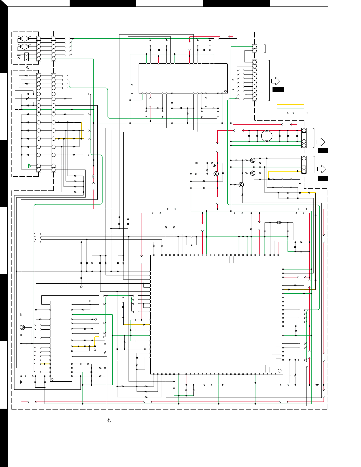
SCHEMATIC DIAGRAM ............................................12
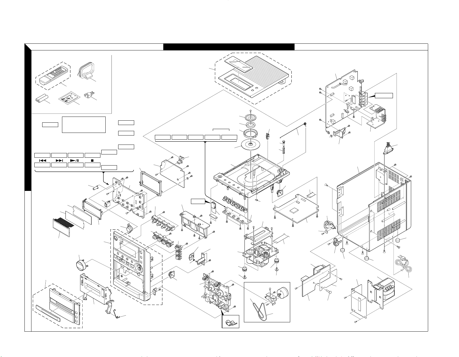
EXPLODED VIEW .....................................................17
PARTS LIST...............................................................18
SPECIFICATIONS..................................BACK COVER
2

Rear cab.
(A80-4503-08)
Voltage selector *
(S62-0124-08)
RXD-M37
EXTERNAL VIEW
<Bottom view>
* Refer to parts list on page 18.
System configuration
SYSTEM RECEIVER SPEAKERS
HM-337-L RXD-M37-L LS-M37-L
HM-337-S RXD-M37-S LS-M37-S
Rubber foot
(G11-2957-08)
3

RXD-M37
SERVICE ADJUSTMENT
Lubrication
The mechanical parts are factory coated with a thin coat of light grease and should not require further
lubrication. If a light grease is applied, be careful not to get any grease on the play/record head or erase
head, hubs, pulleys, tapes reels, drive belts, or switches. Use a good lubricant such as Silicon Lube G322L
or Lubricate.
Service Check
Before aligning the mechanism, wipe off any accumulated dirt with denatured alcohol. Wipe around parts
where the tape contacts and around all rotating parts. Drive belts are specially processed. Do not clean
them with alcohol.
Mechanical Torque
Use a cassette type torque gauge and check the tape mechanism.
Take-up torque 35 to 70 g-cm
Rewind torque 50 g-cm min.
Fast forward torque 50 g-cm min.
Pinch Wheel Pressure
No adjustment to the pinch roller spring is necessary. It should be sufficient to give at least 40 g-cm pull
force.
Tape Head Servicing
Each time the unit is serviced, the face of all heads should be thoroughly cleaned with denatured alcohol or
commercial head cleaning solution. The playback head should be demagnetized with a commercial
demagnetizer. Accumulation of tape oxide during normal operations can cause problems, including loss of
high frequencies and wow and flutter.
Erase Head
The erase head is properly aligned when the tape rides directly between the tape guide on the head without
crinkling the tape.
Play/Record and Playback Head Azimuth Adjustment
To adjust the play/record and playback head azimuth screw:
1. Connect two (2) VTVMs and a dual trace scope to the stereo headphone jack (as shown) with a 32
ohm dummy load. (See Figure 1.)
VTVM VTVM
DUMMY LOAD
JK801
SCOPE
CH1
CH2
Figure 1. Azimuth Adjustment
ADJUSTMENT
4

ADJUSTMENT
2. Insert a 10 kHz test tape (Teac MTT-1141V or Equivalent) into the tape mechanism and play it back.
3. While playing back the test tape, slowly turn the azimuth adjusting screw until the amplitude of both
channel output waveforms is maximum and in phase. (See Figure 2.)
4. Secure the azimuth screw in place with glue or paint after making the adjustment.
Figure 2. Head Output Signal
Tape Speed Adjustment
1. Set the function switch to TAPE.
2. Connect a frequency counter with a 32 ohm dummy load to the stereo headphone jack. (See Figure 3.)
FREQUENCY COUNTER
DUMMY LOAD
JK801
Figure 3. Tape Speed Adjustment
3. Insert and play back a 3 kHz test tape (Teac MTT-111 or Equivalent) into the tape mechanism.
4. Insert an insulated alignment tool and adjust the tape speed potentiometer (MOTOR) until the
frequency counter indicates 2940 Hz to 3090 Hz.
Bias Oscillator Frequency and Level Adjustment
1. Set the function switch to TAPE and the record and play tape mechanism to RECORD.
2. Connect a VTVM and frequency counter to test point R/P HEAD.
3. Adjust bias oscillator coil T360 until the frequency counter indicates 81 kHz ± 0.5 kHz.
4. Confirm the record head voltage equal to: 6-12V.
5. Confirm the erase head voltage equal to: 15-24V.
RXD-M37
5

RXD-M37
TUNER ALIGNMENT PROCEDURE
Equipment needed:
1. AM Signal generator
2. FM Signal generator
3. DC Voltage meter
4. Oscilloscope
5. Output meter (VTVM)
AM Alignment
Step S/G Frequency Dial Setting Indicator Adjust Remarks
1 450 kHz (1 kHz 30% mod.) 612 kHz Connect
oscilloscope or
VTVM to speaker
jack
T201 Adjust until
maximum
output
2 531 kHz (1 kHz 30% mod.) Low end Connect DC voltage
meter to test point Vt
and ground
T202 Adjust until
Vt equal to
1.5 ± 0.05V
3 1602 kHz (1 kHz 30% mod.) High end Same as step 2 Confirm Vt:
6.5~8.5V
4 612 kHz (1 kHz 30% mod.) 612 kHz
Same as step 1 T203 Maximum output
5 1404 kHz (1 kHz 30% mod.) 1404 kHz Same as step 1 VC201 Maximum output
6 Repeat steps 4 and 5 to minimize tracking error
7 999 kHz
(1 kHz 30%mod.)
999 kHz
Same as step 1 Offset is less than
6 dB.
60 cm
AM SIGNAL GENERATOR
AM LOOP ANT
AM LOOP
ANTENNA
DUMMY LOAD
TEST UNIT
VTVM
R-OUT
L-OUT
GND
Figure 4. AM IF/RF Tracking
TEST UNIT
Figure 5. AM Band Frequency Coverage Alignment
GROUND
METER
Vt DC
ADJUSTMENT
6

FM Alignment:
Figure 6. FM Band Frequency Coverage Alignment
Connect FM S/G to ANT inputs (mod 1 kHz 22.5kHz dev.)
Step S/G Frequency Dial Setting Indicator Adjust Remarks
1 87.5 MHz Low end Connect DC voltage
meter to test point Vt
and ground
L203 Adjust until Vt equal to:
1.5 ± 0.05V
2 108 MHz High end Same as step 1 Confirm Vt: 7-9V
3 90.1 MHz 90.1 MHz Connect oscilloscope
or VT/VM to speaker
jack
L204 Adjust until Maximum
output
4 106.1 MHz 106.1 MHz Same as step 3 VC202 Adjust until maximum
output
5 Repeat steps 3 and 4 to minimize tracking error.
FM GENERATOR
DUMMY
ANTENNA
TP1
TEST UNIT
OSCILLOSCOPE
DUMMY LOAD
VTVM
R-OUT
L-OUT
GND
Figure 7. FM Band/Tracking
TEST UNIT
GROUND
METER
Vt DC
RXD-M37
ADJUSTMENT
7

ACEBD
U101
Q101
D108
Q106
Q104
LCD101
CN107
CN109
CN104
CN105
D102
D101
Q103
Q105
CN108
CN103
D103
CN101CN102
DISPLAY
CN110
LED182
LED181
LED180
SW107
FRONT KEY
D106
Q182
Q181
Q180
SW113
SW102
SW101
CN112
SW100
SW108
SW103
SW110
SW111
SW106
CN111
SW104
SW109
SW105
SW112
D105
D104
U102
SW114 SW115 SW116 SW117 SW118
CN113
R143
R144
R145
R101
R104
C104
R100
C108
R107
C116
R142
R140
R141
R139
R137
R138
R136
R6
C118
C107
1
100
50
51
8180
3031
C110
R4
R110
R109
R108
R103
C102
C115
R120
R121
C113
R119
R118
R117
C112
R115
R125
R1
R149
R113
R112
R148
R123
R124
C111
R3
R128
R129
R130
R131
R132
R133
R134
C119
C105
C016
R2
R8
R114
C114
R7
R5
J6
13
J21
R116
R122
J22
J18
R102
J1
J19
J16
J20
J23
J24
J25
J2
J3
J5
R135
J9
R147
J7
X102
X101
C101
C103
J8
C109
J15
J12
J14
J13
R146
L101
J4
R111
J11
40
110
18
18
51
139 1 6 1
1
EB
B
E
B
E
EC EC
R150
R160
R169
R170
R171
R172
R151
R152R153
R154
R155
R168
R156
R164
R165
R167
R166
R159
R163
R162
R157
R158
R161
C118
C117
R180
R181
R182
R186
BE
BEBE
C183
R185
R173
R183
R188
R184
POWER
RDS/
DISPLAY
C180
TIME SET
TIMER ON/OFF
REC
VOLUME UP
TAPE
1
15
13
IGO
6
VOLUME DOWN
TUNER
/BAND
CD
EQ/BASS REPEAT PROG. PRESETDOWN PRESETUP
61
TOP KEY
PC BOARD (Component side view
1
2
3
4
)
5
6
7
8
Refer to the schematic diagram for the value of resistors and capacitors.

F GIKMOHJLN
MAIN
HEADPHONE
U601
Q801
Q802
Q805
Q601
Q203
Q208
Q202
Q602
U201
Q206
Q205
Q201
Q204
U250
Q207
U260
Q263
Q261
Q260
Q262
Q250
Q280
Q252
Q251
Q316
Q315
Q305
Q306
Q301
Q303
Q302
Q304
Q317
Q312
Q308
CN602
Q313
Q307
Q310
Q311
Q309
Q360
CN806
CN201
FM ANT
AM ANT
VD204
VD205
CN801
CN802
D802
Q803
CN601
D302
Q281
U301
CN301
CN302
VD201
CN260
D301
D303
U802
L
CN803
CN805
ZD802
CN804
D803
ZD801
Q806
Q804
CN202
U801
JK801
D202
VD203
VD202
D201
D203
D204
R
SPEAKERS
ZD901
Q902
D907
D904
D902
D901
D903
D905
CN901
D906
POWER
FMVT
AMVT
C220
C236
C2
C293
J10
L
C209
C210
C211
C212
R213
R214
C215
C216
R211R212
R247
R248
C247
TP12
1
112
2413
14
28 15
R807
C825
C823
R809
R810
C824
C826
R808
C805
R805
R801
R813
R6
R313
R326
R341
R333
R314
R325
R334
R819
R815
C829
C817
C822
R812
C322
R802
R806
C806
R814
C248
C205
C273
TP2
C265
R216
R215
C217
R280
C255
TP6
C253
1
11
20
10 1
8
16 9
R259
R265
TP1
C224
R1
R209
C213
R227
R233
R204
C233
TP3
R244
L202
TP4
C202
TP5
C245
C201
C855
C856
C232
R231
C228
R293
C229
R229
C227
R203
R202
C222
C223
C219
C204
C231
C230
C239
C203
C234
L201
21
C200
C828
C827
R823
R824
R210
C214
C237
C226
R236
C208
R811
C821
R217
C218
R208
R219
R221
R234
R207
R285
R205
R609
C613
R607
R611
R605
C609
C284
R286
R284 R256
C256
C258
C259
R310
R339
R309
R347
R327
R323
C311
C312
C305
R328
R348
C326
C310
R321
C626
C331
R343
C624
C628
C629
C622
C618
C614
R608
R612
R606
C610
C616
C612
C608
C606
C604
C602
C282
C632
R624
R622
R344
C332
R804
R803
R322
R610
C621
C617
C615
C611
C607
C605
C603
C281
C601
C631
R623
R621
R320
R312
C350
R316
L302
C320
C302
C301
R311
C319
R315
C324
R304
R336
R337
TP10
TP9
R822
R818
R817
C333
R335
R330
R331
R346
R338
R332
R340
C316
C360
R302
R318
R317
C323
C366
C364
R360
R301
R303
C308
R306
R307
R308
R319
R305
C307
C309
TP7
C321
L301
TP11
MGND
C365
R364
C362
C363
R365
TP13
TP8
R220
R206
R201
R200
C221
R223
R239
R218
C294
R235
C271
C270
C269
R270
R269
C267
R268
R267
C268
R271
C261
C260
C274
C264
C262
C287
R2
R242
C235
C242
R238
C250
R251
R252
C251
R253
R254
C252
R261
C286
R262
C285
R263
R288
R277
R297
C206
R226
EB
EB
EB
EBEB
EB
EB
EBEB
EB
EB
EB
EB
EB
EB
EB
EB
EBE
1
8
16
9
B
EB
EB
EB
E
B
EBEBEB
EB
EB
EB
EB
E
OG I
B
EBEB
EB
EB
EB
CE
EB
EB
15
L205
CF201
J9
15
J31
J22
J26
R613
R600
J36
R830
J34
J33
T360
2
J27
1
15
J30
C820
J39
J35
J32
J40
1
13
4
R816
19
BE
CE
CF202
CF203
C207
R222
R224
J14
R272
J13
R274
R275
R276
J12
J11
J3
J24
R249
R250
J38
J23
R329
J28
R255
R258
C257
13
R243
L806
L807
L808
T203
J4
VC201
C238
T202
GND2
C240
R246
C272
J2
J1
R266
J6
R225
J8
R281
R279
R273
C290
C254
X250
1
C263
OSC1
GND1
6
X260
C266
R257
R283
R232
J15
0SC2
R228
J5
L203
R230
J7
L204
BPF201
L208
T201
VC202
L801
C813
L802
C812
C809
C803
C818
C623
C619
C625
C620
C804
C810
L809
L810
ICP
R821
1
4
J16
J17
J20
R354
J29
J25
C304
C315
C303
J19
C314
C325
C317
C313
J21
J18
R355
R324
C830
R820
C831
C329
C327
C627
C832
C801
C833
BE
J37
C814
C819
C816
C815
112
TIE
C811
C902
C901
R903
R902
R901
CE
C903
C904
C907
C908
F901
RY901
C905
C906
BLACKRED2
14
RED1
AC1
AC2
L901
T901
P2
P1
PC BOARD (Component side view)
1
109
2
3
4
5
6
7
Refer to the schematic diagram for the value of resistors and capacitors.

PRTQS
U703
U701
Q701
Q703
Q705
Q702
U702
D701
CN705
CN702
CN706
CN703
Q704
CN704
CD SERVO
CN701
D702
C735
J2
J4
R722
R723
R725
R726
R727
C734
C740
J23
1
61
21
13
110
13
12
2413
51 80
30
31
50
100
81
1
16
30
151
162
151
C751 C719
X701
C723
J39
C705
C704
C790
C722
J10
J17
J15
J12
J11
J7
J6
C710
J5
J3
C713
R711
C752
L703
L704
J16
J18
J19
J24
C750
L706
J28
J1
R748
J8
J20
J21
J22
J32
J33
J34
J35
J36
J27
R700
R701
R705
R702
R762
R761
R738
R724
R734
R736
C756
R741
C725
C743
C758
C742
R721
C728
R731
R730
C712
C759
C714
R716
R763
EB
R729
R733
R732
C736
C738
C703
C715
C729
C745
C741
C755
C760
C749
R737
R740
C707
R704
R703
C706
R707
C711
C701
C708
R706
C717
C727
C757
J702
R742
C720
GND
C718
C733
R717
TE0
FE0
VREF
C716
C754
J703
R743
J701
R757
R744
R758
R745
R746
R760
R759
R747
R739
R728
RF0
C744
C753
C732
C739
C737
C709
C726
C730
C731
J704
C702
TE03
C721
C748
R735
C747
C746
J31
C724
J29
J38
CM-CHOKE
J26
J30
J25
L705
J13
J14
J9
BE
BE
BE BE
PC BOARD (Component side view
1
2
3
4
5
)
6
7
Refer to the schematic diagram for the value of resistors and capacitors.
11
RXD-M37
Q705
Q701
Q702
CN702
D701
Q703
CN703
(BOTTOM VIEW)
(BOTTOM VIEW)
CN701
U701 : TC9462F
U702 : TA2153FN
U703 : TA2092N
Q701,702 : 8050D
Q703,705 : 8550D
Q704 : 2SC1383R
D701 : 1N4148
D702 : MTZJ5.6B
2/3
MAINCN602
2/3
MAINCN805
CN105
DISPLAY-
3/3
CN705
CN706
(BOTTOM
VIEW)
CN704
D702
Q704
SIGNAL LINE
B LINE
GND LINE
M
M
C716
0.047
+
C749 0.047
C744 0.047
C743 470P
C742 470P
3.3K
R723
3.3K
R722
R725
3.3K
R724
3.3K
SLT
18 63
97
CCE
TSMOD
TEST4
R711 10K
C714 1
100
10
RST
9
EMPH
UHSO
HSO
TEST0
2
1
4
3
A OUT
BCK
VSS1
LRCK
658
7
CLCK
SBOK
MBOV
D OUT
11
10
IPF
13
12
SFSY
DATA
VSS2
VDD1
16
15
14
17
TEST3
TEST2
TEST1
VDD5
96
C713
47u16
BUCK
+
VSS5
91
92
93
90
BUS1
BUS3
BUS2
BUSO
C710
+
22u16
DVSL
LO
DVR
0.01
DVSR
DVDD
RO
72
XVSS
XO
XVDD
787980
XI
77
VSS4
PXI
PXO
VDD4
757673
74
DM OUT
CKSE
DACT
TESIN
TRESIO1
707168
69
IO0
IO1
IO2
IO3
656667
64
R737 33K
C748
C745
120P
R731 10K
R730 68K
R729 220K
LPFN
LPFO
P VREF
26
C712
0.047
C722
C723
47u16
47u16
+
+
MONIT
COFS
SPDA
SPCK
SBSY
20
19
22
21
P2 VREF
TESIOO
VDD2
24
23
25
TMAX
TMAXS
PDO
ZDET
HSSW
28
27
30
29
R733
47K
C736
0.015
R732
15K
C738
47P
R741
R736
2.2K
47K C756
2P
R735
27K
R734
1K
R728
2200.1
VCOREF
VCOF
AVSS1
SLCO
RFI
AVDD1
RFCT
RFZI
RFRP
FEI
SBAD
TSIN
TEI
TEZI
FOO
TRO
VREF
55
FLGB
FLGC
FLGD
VDD3
VSS3
616259
60
2VREF
SEL
FLGA
565758
TEBC
FMO
FVO
DMO
535452
RFGC
51
FEO
C739
2700P
0.01
C737
47u16
C740
+
C734
47u16
40
+
42
C755
0.047
42
38
RFO
40
C747 0.22
C760 0.1
C741 0.22
VREF
43
44
43
38
R727 3.3K
R738
C746
4700P
TEO
44
1K
R726 10K
R721 3.3K
23
1
2
C752
220u16
30
29
3
4
5
6
26
28
27
25
24
L704
10uH
+
C753
0.047
51
5
4
7
6
8
R740
68K
19
7
8
9
10
21
22
18
17
16
R739
57
C750
+
100u16
56
52
10
L703
10uH
GND
2
6
5
6
5
C708 2200P
C711 2200P
16.9344MHz
R717
C727
22
C717
30P
C718
30P
C719
+
47u16
X701
CD L
1
R702
2.2K
GND
CD R
2
3
R701
2.2K
C757
0.047
C751
47u16
R704
47K
R705
10K
C732
0.047
0.047
C731
R703
47K
C701
0.01
FM+
FM-
DM-
DM+
23
16
14
21
2
4
3
1
2
4
3
1
20
12
13
14
15
11
FEOSBAD
TEO
TEN
2VRO
TEB
SEL
LDO
MDI
TNI
FNI
FPI
TPI
RFGC
VCC
GMAD
FEN
SEB
VRO
RFRP
BTC
RFCT
PKC
RF RPIN
RFGO
GVSW
AGCIN
RFO
GND
RFN2
50
49
47
48
46
45
44
43
41
40
42
39
38
37
36
35
34
33
31
32
81
82
83
84
85
86
88
87
90
89
94
93
92
91
95
96
97
99
98
100
CM-CHOKE
C790
0.01
C724
470u16
+
C702
0.022
470u16
M G
D G32
C709
0.047
+
8.5V
1
+8.5V
R762
39K
C707
1 270
R707
C706
270
R706
139K
R761
C721
+8.5V
+8.5V
100uH
L705
7
BUCK
CD-RW
10
CCE
RST
8
9
GND2
BUS 0
BUS 1
6
5
BUS 2
BUS 3
SLT
4
3
2
CLT
1
CLT
1
96
97
100
10
93
92
90
91
0.1
SGND
PEGND3
VIN3
OUT (+)3
PW VCC3
OUT (-)3
11
9
+8.5V
OUT (-)2
PWGND2
VIN2
OUT (+)2
PWVCC2
C729
+8.5V
12
11
10
0.1
C728
8
9
7
VCI
16
14
151314
161817
0.1
C730
PWGND4
OUT (-)4
PWVCC4
OUT (+)4
VIN4
SVCC1
100u16
C735
+
4
2
C725
VIN1
PWVCC1
OUT (+)1
VRI
C758
0.047
6
+8.5V
4
5
3
PWGND1
OUT (-)1
0.1
1
2
24
+8.5V
23
21
2019222123
C726
0.1
2
D
47K
47uH
L706
V CEN
COM
2
1
4
3
E
2
1
4
3
R757 22K
0.047
C720
R759 22K
R760 22K
R758 22K
7
47K
R748
R743 47K
77
5
A
6
B
5
6
F
8
C
10
9
LD
GND
8
10
9
5
4
R746
47K
R747
47K
R745
6
47K
R744
2
4
11
R742 100
T-
12
11
PD
VR
15
14
13
T+
F+
12
11
15
14
13
9
16
F-
16
8
56
52
57
51
R716
270
C704
47u16
+
R763
33
C705
100u16
C715 0.1
+
0.022
C703
+B
+8.5V
+8.5V
+5V
+5V
+5V
+5V
+5V
+5V
+5V
+5V
+5V
+5V
+5V
+5V
+5V
+5V
+5V
+5V
+5V
+5V
+5V
+5V
+5V
+5V
U701
U702
CD DECK
CD
HM-337 (1/3)
U703
PICKUP
1
A BDCE
2
3
4
5
6
7
CAUTION: For continued safety, replace safety critical components only with manufacturer's recommended parts (refer to parts list). indicates safety critical components. For continued protection
against risk of fire, replace only with same type and rating fuse(s). To reduce the risk of electric shock,
leakage-current or resistance measurements shall be carried out (exposed parts are acceptably insulated from the supply circuit) before the appliance is returned to the customer.
The DC voltage is an actual reading measured with a high impedance type voltmeter with a cassette
loaded at playback mode. The measurement value may vary depending on the measuring instruments
12
used or on the product. Bias circuit DC voltage is measured while in the record mode.
U - 6
DOLBY and the double-D symbol
are trademarks of Dolby Laboratories Licensing Corporation.
Noise reduction circuit made
under license from Dolby Laboratories Licensing Corporation.
M-5
M-6

AM ANT
CN260
VD201
Q205
Q204
Q206
VD203
VD202
VD204 VD205
D202
D201
Q202
Q208
Q203
Q252
Q207
Q251
Q260
Q261
Q262
Q263
Q280
Q281
(BOTTOM
CN301CON301
CN302CN302A
CN602
CN601
Q305
Q306
Q315
Q316
Q303
Q301
Q304
Q302
Q317
D302
D303
Q309
Q360
Q310
Q311
Q313
Q312
Q307
Q308
D301
VIEW)
Q601
Q602
ERASE
Rch
Lch
CN801
CN806
CN802
L
R
SPEAKERS
JK801Q801
Q802
ZD801
Q804
Q803
Q805
D803
ZD802
CN803
CN901
D802
ZD901
D902 D904
D903D901
D907
Q902
D905
D906
CN805
CN804
BIAS GND
HEAD/R/P
HEAD/R/P
ERASE HEAD
CN201
FM ANT
Q201
3/3
DISPLAYCN103
1/3
CN701
CD-
3/3
DISPLAYCN101
1/3
CN702
CD-
3/3
DISPLAYCN102
CN202
D204
D203
L
R
Q806
U201 : TA2104AFN
U250 : BU1924F
U260 : TC9257F
U301 : TA8142AP
U601 : TC9422F
U801 : BA5415A
U802 : L7812C
Q201 : 9018
Q202-204,208,260-263,
601,602 : 9014
Q205-207,252,280,310-312,315-317
: 9013G
Q251,281,309,313,804
: 8550D
Q301-306 : 2SC2412K
Q307,308,360,801,802,805
: 8050D
Q803 : KTD2058Y
Q806 : 2SC1383R
D201-204,301-303,802
: 1N4148
D803 : 1N4001
VD201 SVC348T:
VD202-205
ZD801 MTZJ9.1B:
SVC201SPA:
ZD802 MTZJ6.2B:
Q902 8050D:
1N4001D901-904 :
D905,906 RL202:
D907 1N4148:
ZD901 MTZJ5.7B:
PHONES
SIGNAL LINE
B LINE
B LINE
GND LINE
RECORDING LINE
(E)TYPE
ONLY
2423222120
19
181716
151413
FMRF OUT
RF VCC
AMRF IN
FM OSC
AM OSC
OSC OUT
STLED
IF REQ
DET OUT
MPX IN
ST/MO
FM/AM
1
2
345
6
7
8
9
10
11
12
RF GND
FM RF IN
AM LOW CUT
MIX OUT
VCC
AMIF IN
FMIF IN
GND
AGC
QUAD
R OUT
L OUT
1
2
3
4
5
6
7
8
QUAL
R DATA
VREF
MUX
VDD1
VSS1
VSS3
CMP
16
15
14
13
12
11
10
9
RCLK
NC
X0
X1
VDD2
VSS2
T1
T2
11
12
13
14
15
16
17
18
19
20
EE
VDD
AM IN
FM IN
GND
IF IN
B0
B1
AMVT
FMVT
10
9
8
7
6
5
4
3
2
1
ST/MD
AUX
CD
TUNER
IF REQ
DATA
CLOCK
PERIOD
XT
XT
1
2
1
2
3
4
5
6
RCLK
RDA
ST
PERI
PCLK
PDA
10K
R235
10K
R239
R223
0.1
C219
47K
R218
C220
R233 100
C204 0.01
1
C222
C223 330P
C221 0.1
10K
R224
1K
R225
1K
R203
150K
R202
10
15P
C226
100K
R226
33P
C237
390P
C238
T202
0.022
C229
100K
R229
VC201 20P
1000P
C294
3.3K
22u16
C240
+
22K
R242
1
T203
R209 10
R228 10
L203
0.022
C213
R204
0.022
C224
47K
R231
10
R210
10P
VC202
C232 3P
C214
1000P
C233
L204
0.022
18P
C230
1000P
C231
47K
R230
0.047
C234
C239
0.047
0.56uH
L201
47K
R243
100K
R244
22P
C201
8P
C202
4.5T
C245 7P
10uH
L205
T201
270K
R200
330
R201
C242
0.047
0.47
C203
C241
0.047
1000P
C293
4.7u50
C207
+
1
C212
C210 0.01
C209 0.01
CF203
CF202
330
R246
0.022
C235
220u16
C236
+
10K
R234
10K
R207
270K
R205
100
R220
560
R221
1K
R217
1.5K
R206
330K
R208
470K
R219
0.01
C208
0.1
C218
C252 0.1
R254 22
C290 100u10
+
1K
R257
C255
560P
2.2u50
+
C254
270P
C253
51P
C258
0.047
C256
100u10
+
C257
10K
R259
X250
4.332MHz
51P
C259
22
R258
0.1
C251
1K
R284
R256
R238 10K
R279 10K
10
R255
10K
R283
3.3K
R222
1K
R265
0.01
C264
C274 100P
R266 1K C265
R216 1K
R267
1000P
0.022
C270
1K
R270
1
C269
1.5K
R269
C271 0.022
C267
0.022
3.3u50
+
C266
1.5K
R268
C268 0.022
330
R232
R211
12K
12K
R212
R297 10K
R277 10K
X260
7.2MHz
30P
C260
10K
R280
33P
C261
C285 220P
C286 220P
C287 220P
47K
R215
0.022
C217
100K
R288 10K
R276 10K
R274 10K
R275 10K
R261 1K
R262 1K
R263 1K
2
3
1
C211
1
5.6K
R214
1500P
C215
1500P
C216
5.6K
R213
R247
8.2K
8.2K
R248
1000P
C247
C248
1000P
R250
R249
3.3K
3.3K
1
2
3
560
C273
100u16
R272
10K
C272
+
R285
R273
1K
R281
4.7K
10K
100K
R286
R271
10K
123456789
1011121314
GND
L-IN1
L-IN2
L-IN3
L-IN4
LSWOUT
L-VR-IN
L-B1
L-B2
L-B3
LTONE-0
L-T1
VREF
CK
282726
252423
22
21
2019181716
15
VDD
R-IN1
R-IN2
R-IN3
R IN4
RSWOUT
R-VR-IN
R-B1
R-B2
R-B3
RTONE-0
R-T1
STB
DATA
2
3
12
14
15
16
13
9
7
6
5
4
11
10
1
8
NF1
PRE OUT1
GND
REC OUT2
NF4
REC IN2
ALC
REC IN1
NF2
PRE OUT2
VCCCGREC OUT1
NF3
CH1/A
CH2/A
1
2
3
4
5
1
2
3
4
5
121
2
1
2
3
CD L
CD GND
CD R
1
2
34CLK
DATA
VOL STB
D GND
VREF1
VREF
VREF2
ALC
300K180K
300K180K
180K300K
180K300K
2.2K
R353
100u16
C303
+
100
R305
0.018
C307
6.8K
R307
470
R309
100u16
C313
+
1
C311
1
C309
3K
R348
3K
R347
100K
R324
100K
R323
1M
R339
47u16
+
C317
10K
R327
10K
R328
C326
47MH
L302
15K
R316
82P
C322
1000P
C320
10K
R312
100u16
C304
+
100
R306
6.8K
R308
0.018
C308
470
R310
100u16
C314
+
2.2u50
C315
+
1
C310
1000P
C302
1000P
C301
4.7K
R320
4.7K
R319
0.022
C324
150P
R318
220K
150P220K
R317 C323
10K
R303
10K
R301
R302
10K
R304
10K
100u16
C327
+
4.7K
R326
10K
R334
0.022
C305
10K
R333
10K
R314
390
R329
10K
R313
220u16
C325
+
R354
100K
R346
10K
R337
100u16
+
4.7K
R330
4.7K
R331
0.1
C316
10K
R340
0.022
C333
47K
R336
47K
R338
100K
R332
4.7K
R335
C366 0.022
82
R364
C365 330u16
+
1000P
C364
1000P
C363
27K
R365
0.01
C362
0.012
4.7
R360
T360
47MH
L301
15K
R315
10K
R311
82P
C321
1000P
C319
10K
R321
10K
R322
0.47
C604 1
C606 1
C608 1
C612 1
C616 0.47
C620 1u50
+
C618 0.47
C622 1500P
C625 100u16
+
C626 0.022R600 390
C332 1500P C331
0.47
C603 1
C605 1
C607 1
C611 1
C615 0.47
C617 0.47
C619 1u50
+
C621 1500P
C623 22u16
+
C624 0.1
1
C609
470
R605
R607 390K
470
R609
4.7K
R611
C613 47P
4.7K
R612
R608
1
C610
C614
470
R606
470
R610
C629 220P
C628 220P
220u16
C627
+
470
R613
C601
1K
R621
47K
R623
220P
C631
C602
1K
R622
47K
R624
220P
C632
12
4
9
6
44K
1
2
10
11
44K
5
7
8
3
100P
C824
330P
C826
330P
C825
100P
C823
33K
R810
0.47u50
+
C804
47u16
+
C809
47u16
+
C810
330u25
+
C818
1.5K
R808
0.47u50
+
C803
33K
R809
0.1
C816
0.1
C815
100u16
C814
+
100u16
C813
+
3300u16
+
C812
3300u16
+
C811
4700u25
C819
+
0.1
C817
0.1
C820
3
4
2
1
55
2
4
3
1
1K
R812
1K
R811
1500P
C822
1500P
C821
220uH
L808
150
R824
150
R823
220uH
L807
4.7uH
0.022
C827
0.022
C828
L806
33u10
C801
+
4.7K
R803
47K
R804
10K
R814
10K
R813
R806 3.9K R805 3.9K
C806 330P C805 330P
12K
R801
12K
R802
100K
R817
390
R816
F20
ICP
3.3K
R818
22
R815
100u16
C830
+
C829 0.22
INOUT
GND
100uH
L809
68
R820
10u16
C833
+
100u10
C832
+
22
R822
390
R821
220u16
C831
+
1/4W
33
44
22
11
47uH
L810
0.1
C902
220u16
C901
+
100
R901
330
R902
RY901
T901
T902
1000P
C903
C906
1000P
C908
0.022
1000P
C907
F901
3.15A
50/60Hz
: AC110-120V/220-240V~
: AC230V~ 50Hz
: AC240V~ 50Hz(X)
(E)
(M)
128.5V
GND
1
2
3
4
5
6
7
8
9
MUTE
5.6V
5V
PLAY/REC
L.V. DET
12V
P SW
GND
BIAS CONT
6
5
4
4
5
6
GND
14.5V
P SW
5.6V
+14.5V
+5.6V
+14.5V +14.5V
+8.5V+8.5V
+8.5V
+8.5V
10K
R830
+3.6V
C262 0.022
C263 100u10
+
L901 L902
C905
0.022
C904 0.1
+9V
+7.7V
C360
390K
47P
C329
2.2K
1500P
+5.6V
+3.6V +3.6V
+3.6V +3.6V
2.5T
3.5T
0.022
C206
0.047
C227
CF201
0.1
1.5K
R807
+5.6V
+5.6V
+5.6V
ch2
ch1
ch1
ch2
10K
R819
B
+B
1
C312
L208
1/2W
3 GND
16
15
14
15
14
16
+12V +12V
+12V
+12V
+B
+B
+B
+5V
+B
+B
+12V +12V
+12V
+B
+B
+5V
+5V
+12V
+12V
+12V
+5V +5V
+5V
+5V
+12V
+B
+5V
+B
U201
U250
U260
U601
U301
U802
MAIN
HEADPHONE
POWER
U801
HM-337 (2/3)
1
2
3
4
5
6
7
FHJ LNGIKMO
RXD-M37
13
P - 4
E - 3
E - 3
Q - 7
CAUTION: For continued
safety, replace safety critical components only with
manufacturer's recommended parts (refer to
parts list). indicates
safety critical components. For continued protection against risk of fire,
replace only with same
type and rating fuse(s).
To reduce the risk of
electric shock, leakagecurrent or resistance
measurements shall be
carried out (exposed
parts are acceptably insulated from the supply circuit) before the appliance
P - 7
is returned to the customer.
The DC voltage is an actual reading measured with a
high impedance type voltmeter with a cassette loaded
at playback mode. The measurement value may vary
depending on the measuring instruments used or on
the product. Bias circuit DC voltage is measured while
in the record mode.
DOLBY and the double-D symbol are trademarks of
Dolby Laboratories Licensing Corporation. Noise
reduction circuit made under license from Dolby Laboratories Licensing Corporation.
14

P QSUWYRTVX
CN103
CN107 CN110
CN108 CN111
CN112
CN113
D103
Q101
CN105
CN109CN102CN101
D102
D101
Q103
Q104
Q105
Q106
CN104
D104
D105
LED181
Q180
LED180
Q182
Q181
LED182
SW107 SW108
POWER TIMER
ON/OFF SET
TIME
SW109
PLAY/
PAUSE
SW 110 SW 111
SKIP+/
SEARCH+
SW112 SW113
VOL+STOP
SW101
/BAND
TUNERCD
SW100 SW102
SEARCH-
RDS/REC
DISPLAY
SW103 SW104
SKIP-/
SW105
VOL-
SW106
TAPE
SW116
PROG.
SW117
DOWN
PRESET
SW118SW115
REPEAT
SW114
BASS
EQ/
UP
PRESET
M
2/3
CN260
MAIN
2/3
MAIN
CN804
2/3
MAIN
CN601
to IC WRITER
1/3
CN705
CD ASSY
U101 : 87EP26F-4K76
U102 : RPM6938-V4
Q101,180,181 : 9014
Q103,105,182 : 8550D
Q104,106 : 9013G
D101-105 : 1N4148
B LINE
B LINE
GND LINE
1
2
345
678
9
10
11
12
131415
1617181920
21
22
232425
2627282930
31
32
333435
3637383940
COM1
COM2
COM3
1
2
3
4
5
6
PDA
PCLK
PERI
ST
RDA
RCLK
1
2
3
4
5
5.6V
5V
GND
1
2
3
4
5
1
2
3
KGND
1
2
3
65432 1
GND
65432 1
8079787776757473727170696867666564636261605958575655545352
51
50
49
48
47
46
45
44
43
42
41
40
39
38
37
36
35
34
33
32
31
1
2
345
678
9
10
11
12
131415
1617181920
21
22
23
24
25
2627282930
81
82
83
84
85
86
87
88
89
90
91
92
93
94
95
96
97
98
99
100
SEG20
SEG19
SEG18
SEG17
SEG16
SEG15
SEG14
SEG13
SEG12
SEG11
SEG21
SEG22
SEG23
SEG24
SEG25
SEG26
SEG27
SEG28
SEG29
SEG30
SEG31
SEG32
SEG33
SEG34
SEG35
SEG36
SEG37
SEG38
SEG39
VDD2
VSS2
BOOT
VAR EF
AD K1
AD K2
L.V. DET
PWR DETECT
STAREO
RDS DATA
OVERLOAD
CLT(SLEND)
SLT
MOTOR OP
MOTOR CL
BUS3
BUS2
BUS1
BUCO
BUCK
CCE
VSS1
XOUT
XIN
RESET
XTOUT
XTIN
TEST
BIAS CONTROL
REMOTE
MUTE
MP3 SCLK
MP3 SDATA
MP3 REQ
BACKLIGHT
PROTECT
PLAY/REC
RECSW R/WAIT
RECSW F
SOLENOID
MODE SW
VOL STB
POWER
HALF SW
JOG BVOL DATA
JOG AVOL CLK
RDS CLK
T.MOTOR
TAPE PHOTO
CD RW
CDRES
SEG10
SEG9
SEG8
SEG7
SEG6
SEG5
SEG4
SEG3
SEG2
SEG1
SEG0
COM3
COM2
COM1
COM0
VLC
PLL DATA
PLL CLK
PLL PER100
VDD1
LCD01
LCD02
LCD03
LCD04
LCD05
LCD06
LCD07
LCD08
LCD09
LCD10
LCD11
LCD12
LCD13
LCD14
LCD15
LCD16
LCD17
LCD18
LCD19
LCD20
LCD21
LCD22
LCD23
LCD24
LCD25
LCD26
LCD27
LCD28
LCD29
LCD30
LCD31
LCD32
LCD33
LCD34
LCD35
LCD36
LCD37
LCD38
LCD39
LCD40
LCD07
LCD02
LCD01
LCD06
LCD05
LCD04
LCD03
LCD11
LCD10
LCD09
LCD08
LCD15
LCD14
LCD13
LCD12
LCD34
LCD16
LCD25
LCD17
LCD18
LCD19
LCD20
LCD23
LCD21
LCD22
LCD24
LCD26
LCD27
LCD28
LCD29
LCD32
LCD30
LCD31
LCD33
LCD35
LCD36
LCD37
LCD38
LCD39
LCD40
10K
R142
0.1
C119
10K
R137
R138
8.2K
R135 10K
33
32
31
39
36
35
34
42
43
R141
10K
R139
10K
40
R140 22
R136 1K
R145 1K
R144 1K
R143 1K
470u10
C101
+
C102 0.1
43
42
26
kHz
32.768
X102
C108 24P
C107 24P
X101
7.2MHz
2.2K
R104
24P
C106
24P
C105
47K
R101
10u16
+
C103
3.3K
R102
10K
0.1
C104
R103
29
30
20
19
18
27
28
4.7K
R114
8
16
21
22
25
24
10K
R111
10K
R112
R113
10K
10
CD RW
RST
CCE
BUCK
BUS0
BUS1
BUS2
BUS3
SLT
CLT
987654321
SI2
SO2
SCK2
678
WAIT
RESET
BOOT
345
GND
5V
12
VOL STB
VOL DATA
VOL CLK
1321
MUTE
7
PSW
GND
BIAS CONT
89
PLAY/REC
5.6V
12V
L.V. DET
4653
5V
2
16
45
22
8
R146 10K
47uH
L101
R108 1K
21
R109 10K
24
R110 1K
25
10K
R116
4.7K
R115
0.022
C112
100K
R117
100K
R125
R118
100K
4.7K
R119
27
0.022
C113
100K
R121
10K
R120
6
MODE SW.
SOLENOID
H-OUT
TAPE TOUCH-SW.
H-VCC
312
NC
45
MOTOR+
REC. SW.
78
18
R149 10K
R148 10K
20
R123 120K
28
45
19
0.01
C114
26
OUT
GND
IN
47u10
C180
+
10
R180
3.3K
R183
10K
R181
100
R184
100K
R186
10K
R182
1K
R188
100
R185
C118 0.01
470
R161 R162
1.5K 1K
R163 R164
2.7K 3.9K
R165 R166
2.7K 3.9K
R167
5.6K
R168 R169
8.2K 15K
R170
27K
R171 R172
82K
75
R173 R160
C117 0.01
75
470
R150 R151
680 3.3K
R1523KR153
6.8K
R154 R156
8.2K
R155
7.5K
R157
15K
R158
27K 82K
R159
R147 10K
R134 10K
0.01
C116
R133 10K
R132 10K
R131 10K
R130 10K
R129 10K
R128 10K
C115
0.01
29
30
31
32
3334353639
40
1
2
3
4
5
6
7
8
TAPE TOUCH SW.
H-VCC
H-OUT
COM
SOLENOID
MODE SW.
REC. SW.
MOTOR+
B
+B
1K
R124
0.022
C110
220u10
C109
+
10
R122
10K
R107
COM0
B L
REM
AD-K1
AD-K2
EQ
REP
PROG
PR D
PR U
+5.6V
+B
+5V
+5.6V
+12V
+5V
+12V
+5V
+12V
+B +B
+B
+5V+5V
+5.6V +5.6V
+5.6V
+5V
+B
+5V
+5V
+5.6V
+5V
+5V
+5.6V
U101
LCD101
U102
FRONT KEY
TOP KEY
DISPLAY
(W991S-337)
CASSETTE DECK
HM-337(3/3)
COL
P
8
A
FIJB
E
M
D
L
C
GK
1
1
COM0
2
COM1
3
COM2
4
COM3
5
1F
1H
1G
1E
6
1A
1I
1N
1M
7
1B
1J
1K
1L
9
2F
2H
2G
2E
10
2A
2I
2N
2M
13
3F
3H
3G
3E
14
3A
3I
3N
3M
15
3B
3J
3K
3L
17
4F
4H
4G
4E
18
4A
4I
4N
4M
19
4B
4J
4K
4L
11
2B
2J
2K
2L
8
1C
1D
12
2C
2D
16
3C
3D
20
4C
4D
COM/PIN #
COM-0
COM-1
COM-2
COM-3
2924
COL
5C
5D
30
7F
7H
7G
7E
31
7A
7I
7N
7M
32
7B
7J
7K
7L
21
5F
5H
5G
5E
22
5A
5I
5N
5M
23
5B
5J
5K
5L
25
6F
6H
6G
6E
26
6A
6I
6N
6M
27
6B
6J
6K
6L
34
8F
8H
8G
8E
35
8A
8I
8N
8M
36
8B
8J
8K
8L
28
6C
6D
33
7C
7D
37 38 39
ROCK
CLASSIC
POP
JAZZ
8C
8D
40
P( )
H
N
RXD-M37
1
2
3
4
5
M - 4
6
7
15 16
The DC voltage is an actual reading measured with a high impedance type voltmeter with a cassette loaded at playback mode.
The measurement value may vary depending on the measuring instruments used or on the product. Bias circuit DC voltage is
measured while in the record mode.
M - 5
M - 7
E - 1
DOLBY and the double-D symbol are trademarks of Dolby Laboratories
Licensing Corporation. Noise reduction circuit made under license from Dolby
Laboratories Licensing Corporation.
CAUTION: For continued safety, replace
safety critical components only with manufacturer's recommended parts (refer to
parts list). indicates safety critical com-
ponents. For continued protection against risk of fire, replace only with
same type and rating fuse(s). To reduce
the risk of electric shock, leakage-current
or resistance measurements shall be carried out (exposed parts are acceptably
insulated from the supply circuit) before the
appliance is returned to the customer.
ED1
SW100
CD
SW102
TAPE
SW113
volume
UP
SW106
volume
DOWN
SW101
POWER
SW104
SW107
display
TUNER
band
SW109
timer
set
SW108
timer
on/of
SW103
rec
SW105 SW112 SW110 SW111
SW114
EQ/
X-bass
SW115
repeat
SW116
program
SW117-SW118
+
p.call
PHONES
JK801
CN802
SPEAKERS
PR
A
B
C
D
E
F
G
φ2.6x8
φ2.6x10
φ3x6(F)
φ3x8
φ3x10
φ2x5(BLK)
φ3x12
: N89-2608-46
: N89-2610-46
: N32-3006-46
: N89-3008-46
: N89-3010-46
: N89-2005-45
: N89-3012-46
747
722
721
720
709
718
719
622
664
663
BM
BS
755
757
756
754
712
723
710
776
643
627
644
646
x2
645x2
672x2
672x2
678
678
629
642
615
614
613
617
660
665
724
666
603
605
604
661
607
608
642
667
T901
T902
651
651
652
658
650
L902
649
K901
641
634
638
637
636
635
631
632
630
640
675
673
677
674
A
E
D
D
B
B
B
B
E
A
F
F
E
726
725
E
E
E
A
A
A
A
A
B
E
E
E
D
E
F
F
E
B
B
D
D
D
x2
Bx2
Bx2
Bx2
Ex2
Ax2
Ax2
Ax2
Bx7
Ax2
Ax2
Gx2
Gx2
Fx2
Fx2
Fx2
Ex2
Ex2
651x2
(HM-337)
RXD-M37
Parts with exploded numbers larger than 700 are not supplied.
A
B
C
1
2
17
EXPLODED VIEW (UNIT)
RXD-M37

18
RXD-M37
✽ New Parts
Parts without Parts No. are not supplied.
Les articles non mentionnes dans le Parts No. ne sont pas fournis.
Teile ohne Parts No. werden nicht geliefert.
New
Ref. No
Add-
ress
Parts
Parts No.
Description
RXD-M37-L/M37-S
- ✻ B60-5466-08 INSTRUCTION(E) 88-00337-07
- ✻ B60-5467-08 INSTRUCTION 88-00337-06 EL
- ✻ H10-7941-08 POLYSTYRENE(L) 86-00337-00
- ✻ H10-7942-08 POLYSTYRENE(R) 86-00337-01
- ✻ H60-1289-08 ITEM CARTON 89-00337-02 E
- ✻ H60-1290-08 ITEM CARTON 89-00337-04 M
- ✻ H60-1291-08 ITEM CARTON 89-00337-03 X
- ✻ H60-1295-08 ITEM CARTON 89-00337-01 L
- ✻ T19-0237-08 SPEAKER UNIT 00-00337-00 EX
- ✻ T19-0238-08 SPEAKER UNIT 00-00337-01 L
- ✻ T19-0239-08 SPEAKER UNIT 00-00337-02 M
603 2A ✻ A53-2451-08 CASS LID ASSY 00-00337-04
604 2A ✻ G01-4373-08 CASS LID SPRIN 36-00337-00
605 2A ✻ A53-2452-08 CASS LID BRKT 48-00337-00
607 2A ✻ A60-2419-08 FRONT CAB ASSY 00-00337-05 EL
607 2A ✻ A60-2420-08 FRONT CAB ASSY 00-00337-07 MX
608 2A ✻ K29-8426-08 POWER KNOB 53-00337-01
613 2A ✻ B38-0272-08 LCD DISPLAY 91-00337-00
614 2A ✻ B11-1611-08 LCD FILTER 43-00337-05
615 2A ✻ B19-1670-08 LIGHT GUIDE 43-00337-03
617 2A ✻ J19-6435-08 LIGHT GUIDE BR 48-00337-01
627 2B ✻ K29-8427-08 EQ/BASS KNOB 53-00337-03
629 2B N29-0295-08 E RING M3 35-00003-00
630 1B G01-4362-08 EM3 CD EJECT S 36-00003-04S
631 1B J52-0047-08 CD DOOR SW DLS- 16-00000-09
632 1B D10-5077-08 NSX1 PUSH ROD 55-00141-02
634 1B ✻ F07-2028-08 CD COVER ASSY 00-00337-06
635 1B J19-6420-08 OP3223 Metal P 39-03223-00
636 1B T99-0692-08 OP192 Magnet 2 97-09019-00
637 1B J19-6419-08 UMS4200 Stabil 49-04200-00
638 1B ✻ J11-0904-08 Stabilizer ( 55-07953-03
640 1B ✻ A02-3108-08 CD TRAY ASS’Y 00-00337-07
641 1C ✻ G01-4374-08 CD COVER SPRIN 36-00337-01
642 1B,2B D39-0361-08 DAMPER GEAR B4 63-00303-01
643 2B F07-2026-08 PICKUP COVER 48-00088-07
644 2B ✻ D40-1845-08 CD MECHANISM D 98-00337-00
645 2B J02-1563-08 CD DAMPER (314 81-02750-00
646 2B J02-1564-08 CD DAMPER (314 81-02750-01
649 1C ✻ A80-4503-08 REAR CABINET 61-04200-00G
650 2C E30-7342-08 AC POWER CORD 30-00003-11 X
650 2C E30-7343-08 AC POWER CORD 30-00020-06E ELM
651 2C G11-2957-08 RUBBER FOOT 81-04200-00
652 2C ✻ J19-6436-08 AC CORD HOLDER 48-00337-10
658 2C ✻ N29-0297-08 FIBER WASHER 35-10019-00
660 2A ✻ K29-8428-08 DISPLAY/REC KN 53-00337-02
661 2A ✻ K29-8429-08 VOLUME KNOB 53-00337-00
662 2B ✻ J19-6433-08 CASS LID LATCH 55-00005-01
663 2B ✻ G01-4371-08 CASS LATCH SPR 36-00005-02
664 2B ✻ J22-1259-08 CASS LID LATCH 55-00005-00
665 2A ✻ K29-8430-08 SERACH KNOB 53-00337-04
666 2B ✻ K29-8431-08 CD/TUNER/TAPE 53-00337-05
667 2B ✻ D40-1846-08 CASS DECK MECH 94-30337-00
672 2B ✻ N09-5542-08 CD DAMPER SCRE 40-52610-03
Desti-
nation
1
Re-
marks
✽ New Parts
Parts without Parts No. are not supplied.
Les articles non mentionnes dans le Parts No. ne sont pas fournis.
Teile ohne Parts No. werden nicht geliefert.
New
Ref. No
673 1A ✻ F07-2029-08 ANT TERMI CVR 48-04200-50
674 1A T90-0908-08 AM ANTENNA 23-04910-02
675 1A ✻ A70-1690-08 REMOTE CONTROL V-RE-KEN337 EL
675 1A ✻ A70-1691-08 REMOTE CONTROL M-RE-KEN337 MX
677 1A E03-0115-05 AC PLUG ADAPTER 97-02755-00 M
678 2B,1C ✻ E41-1350-08 FFC 16 PIN CAB 25-61070-00
Add-
ress
Parts
Parts No.
Description
ELECTRICS PARS
LED180 ✻ B30-2676-08 LED,BLUE 02-30337-08
LED181 ✻ B30-2674-08 LED L-934LSRD 02-30934-05
LED182 ✻ B30-2676-08 LED,BLUE 02-30337-08
C101 CE04KW1A471M ELECTRO 470UF 10WV
C102 CK73GB1H104K CHIP C 0.10UF K
C103 CE04KW1C100M ELECTRO 10UF 16WV
C104 CK73GB1H104K CHIP C 0.10UF K
C105-108 CC73GCH1H240J CHIP C 24PF J
C109 CE04KW1A221M ELECTRO 220UF 10WV
C110 CK73GB1H223K CHIP C 0.022UF K
C112,113 CK73GB1H223K CHIP C 0.022UF K
C114-118 CK73GB1H103K CHIP C 0.010UF K
C119 CK73GB1H104K CHIP C 0.10UF K
C180 CE04KW1A470M ELECTRO 47UF 10WV
C201 CC73GCH1H220J CHIP C 22PF J
C202 CC73GCH1H080J CHIP C 8.0PF J
C203 ✻ C90-5820-08 CHIP C 0.47UF K
C204 CK73GB1H103K CHIP C 0.010UF K
C206 CK73GB1H223K CHIP C 0.022UF K
C207 CE04KW1H4R7M ELECTRO 4.7UF 50WV
C208-210 CK73GB1H103K CHIP C 0.010UF K
C211,212 CK73GB1H105Z CHIP C 1.0UF Z
C213,214 CK73GB1H223K CHIP C 0.022UF K
C215,216 CK73GB1H152K CHIP C 1500PF K
C217 CK73GB1H223K CHIP C 0.022UF K
C218,219 CK73GB1H104K CHIP C 0.10UF K
C220 CK73GB1H105Z CHIP C 1.0UF Z
C221 CK73GB1H104K CHIP C 0.10UF K
C222 CK73GB1H105Z CHIP C 1.0UF Z
C223 CK73GB1H331J CHIP C 330PF J
C224 CK73GB1H223K CHIP C 0.022UF K
C226 CC73GCH1H150J CHIP C 15PF J
C227 CK73GB1H473K CHIP C 0.047UF K
C229 CK73GB1H223K CHIP C 0.022UF K
C230 CC73GCH1H180J CHIP C 18PF J
C231 CK73GB1H102K CHIP C 1000PF K
C232 CC73GCH1H030J CHIP C 3.0PF J
C233 CK73GB1H102K CHIP C 1000PF K
C234 CK73GB1H473K CHIP C 0.047UF K
C235 CK73GB1H223K CHIP C 0.022UF K
C236 CE04KW1C221M ELECTRO 220UF 16WV
C237 CC73GCH1H330J CHIP C 33PF J
C238 ✻ C91-1685-08 FILM C 390PF J
C239 CK73GB1H473K CHIP C 0.047UF K
C240 CE04KW1C220M ELECTRO 22UF 16WV
C241 CK73GB1H473K CHIP C 0.047UF K
C242 CK73GB1H473K CHIP C 0.047UF K
Desti-
nation
2
Re-
marks
PARTS LIST
L : Scandinavia K : USA P : Canada R : Mexico C : China I : Malaysia
Y : PX(Far East,Hawaii) T : England E : Europe G : Germany V : China(Shanghai)
Y : AAFES(Europe) X : Australia Q : Russia H : Korea M : Other Areas indicates safety critical components .
L : Scandinavia K : USA P : Canada R : Mexico C : China I : Malaysia
Y : PX(Far East,Hawaii) T : England E : Europe G : Germany V : China(Shanghai)
Y : AAFES(Europe) X : Australia Q : Russia H : Korea M : Other Areas indicates safety critical components .

✽ New Parts
Parts without Parts No. are not supplied.
Les articles non mentionnes dans le Parts No. ne sont pas fournis.
Teile ohne Parts No. werden nicht geliefert.
New
Ref. No
C245 CC73GCH1H070D CHIP C 7.0PF D
C247,248 CK73GB1H102K CHIP C 1000PF K
C251,252 CK73GB1H104K CHIP C 0.10UF K EL
C253 CK73GB1H271K CHIP C 270PF K EL
C254 CE04KW1H2R2M ELECTRO 2.2UF 50WV EL
C255 CK73GB1H561J CHIP C 560PF J EL
C256 CK73GB1H473K CHIP C 0.047UF K EL
C257 CE04KW1A101M ELECTRO 100UF 10WV EL
C258,259 ✻ C90-5819-08 CHIP C 51PF F EL
C260 CC73GCH1H300J CHIP C 30PF J
C261 CC73GCH1H330J CHIP C 33PF J
C262 CK73GB1H223K CHIP C 0.022UF K
C263 CE04KW1A101M ELECTRO 100UF 10WV
C264 CK73GB1H103K CHIP C 0.010UF K
C265 CK73GB1H102K CHIP C 1000PF K
C266 CE04KW1H3R3M ELECTRO 3.3UF 50WV
C267,268 CK73GB1H223K CHIP C 0.022UF K
C269 CK73GB1H105Z CHIP C 1.0UF Z
C270,271 CK73GB1H223K CHIP C 0.022UF K
C272 CE04KW1C101M ELECTRO 100UF 16WV
C273 CK73GB1H104K CHIP C 0.10UF K
C274 CC73GCH1H101J CHIP C 100PF J
C285-287 CK73GB1H221K CHIP C 220PF K
C290 CE04KW1A101M ELECTRO 100UF 10WV EL
C293 CK45FB1H102K CERAMIC 1000PF K
C294 CK73GB1H102K CHIP C 1000PF K
C301,302 CK73GB1H102K CHIP C 1000PF K
C303,304 CE04KW1C101M ELECTRO 100UF 16WV
C305 CK73GB1H223K CHIP C 0.022UF K
C307,308 CK73GB1H183K CHIP C 0.018UF K
C309-312 CK73GB1H105Z CHIP C 1.0UF Z
C313,314 CE04KW1C101M ELECTRO 100UF 16WV
C315 CE04KW1H2R2M ELECTRO 2.2UF 50WV
C316 CK73GB1H104K CHIP C 0.10UF K
C317 CE04KW1C470M ELECTRO 47UF 16WV
C319,320 CK73GB1H102K CHIP C 1000PF K
C321,322 CC73GCH1H820J CHIP C 82PF J
C323,324 CK73GB1H151J CHIP C 150PF J
C325 CE04KW1C221M ELECTRO 220UF 16WV
C326 CK73GB1H223K CHIP C 0.022UF K
C327 CE04KW1C101M ELECTRO 100UF 16WV
C329 CE04KW1C101M ELECTRO 100UF 16WV
C331,332 CK73GB1H152K CHIP C 1500PF K
C333 CK73GB1H223K CHIP C 0.022UF K
C360 ✻ C91-1682-08 FILM 0.012UF K
C362 CK73GB1H103K CHIP C 0.010UF K
C363,364 CK73GB1H102K CHIP C 1000PF K
C365 CE04KW1C331M ELECTRO 330UF 16WV
C366 CK73GB1H223K CHIP C 0.022UF K
C601,602 ✻ C90-5820-08 CHIP C 0.47UF K
C603-612 CK73GB1H105Z CHIP C 1.0UF Z
C613,614 CC73GCH1H470J CHIP C 47PF J
C615-618 ✻ C90-5820-08 CHIP C 0.47UF K
C619,620 CE04KW1H010M ELECTRO 1.0UF 50WV
C621,622 CK73GB1H152K CHIP C 1500PF K
Add-
ress
Parts
Parts No.
Description
Desti-
nation
3
Re-
marks
✽ New Parts
Parts without Parts No. are not supplied.
Les articles non mentionnes dans le Parts No. ne sont pas fournis.
Teile ohne Parts No. werden nicht geliefert.
New
Ref. No
C623 CE04KW1C220M ELECTRO 22UF 16WV
C624 CK73GB1H104K CHIP C 0.10UF K
C625 CE04KW1C101M ELECTRO 100UF 16WV
C626 CK73GB1H223K CHIP C 0.022UF K
C627 CE04KW1C221M ELECTRO 220UF 16WV
C628,629 CK73GB1H221K CHIP C 220PF K
C631,632 CK73GB1H221K CHIP C 220PF K
C701 CK73GB1H103K CHIP C 0.010UF K
C702,703 CK73GB1H223K CHIP C 0.022UF K
C704 CE04KW1C470M ELECTRO 47UF 16WV
C705 CE04KW1C101M ELECTRO 100UF 16WV
C706,707 CK73GB1H105Z CHIP C 1.0UF Z
C708 CK73GB1H222K CHIP C 2200PF K
C709 CK73GB1H473K CHIP C 0.047UF K
C710 CE04KW1C220M ELECTRO 22UF 16WV
C711 CK73GB1H222K CHIP C 2200PF K
C712 CK73GB1H473K CHIP C 0.047UF K
C713 CE04KW1C470M ELECTRO 47UF 16WV
C714 CK73GB1H105Z CHIP C 1.0UF Z
C715 CK73GB1H104K CHIP C 0.10UF K
C716 CK73GB1H473K CHIP C 0.047UF K
C717,718 CC73GCH1H300J CHIP C 30PF J
C719 CE04KW1C470M ELECTRO 47UF 16WV
C720 CK73GB1H473K CHIP C 0.047UF K
C721 CK73GB1H103K CHIP C 0.010UF K
C722,723 CE04KW1C470M ELECTRO 47UF 16WV
C724 CE04KW1C471M ELECTRO 470UF 16WV
C725,726 CK73GB1H104K CHIP C 0.10UF K
C727 CK73GB1H103K CHIP C 0.010UF K
C728 CK73GB1H104K CHIP C 0.10UF K
C730 CK73GB1H104K CHIP C 0.10UF K
C731,732 CK73GB1H473K CHIP C 0.047UF K
C734 CE04KW1C470M ELECTRO 47UF 16WV
C735 CE04KW1C101M ELECTRO 100UF 16WV
C736 CK73GB1H153K CHIP C 0.015UF K
C737 CK73GB1H103K CHIP C 0.010UF K
C738 CC73GCH1H470J CHIP C 47PF J
C739 CK73GB1H272K CHIP C 2700PF K
C740 CE04KW1C470M ELECTRO 47UF 16WV
C741 CK73GB1H224K CHIP C 0.22UF K
C742,743 CK73GB1H471K CHIP C 470PF K
C744 CK73GB1H473K CHIP C 0.047UF K
C745 CC73GCH1H121J CHIP C 120PF J
C746 CK73GB1H472K CHIP C 4700PF K
C747 CK73GB1H224K CHIP C 0.22UF K
C748 CK73GB1H104K CHIP C 0.10UF K
C749 CK73GB1H473K CHIP C 0.047UF K
C750 CE04KW1C101M ELECTRO 100UF 16WV
C751 CE04KW1C470M ELECTRO 47UF 16WV
C752 CE04KW1C221M ELECTRO 220UF 16WV
C753 CK73GB1H473K CHIP C 0.047UF K
C755 CK73GB1H473K CHIP C 0.047UF K
C756 CC73GCH1H020C CHIP C 2.0PF C
C757,758 CK73GB1H473K CHIP C 0.047UF K
C760 CK73GB1H104K CHIP C 0.10UF K
Add-
ress
Parts
Parts No.
Description
Desti-
nation
4
Re-
marks
PARTS LIST
RXD-M37
L : Scandinavia K : USA P : Canada R : Mexico C : China I : Malaysia
Y : PX(Far East,Hawaii) T : England E : Europe G : Germany V : China(Shanghai)
Y : AAFES(Europe) X : Australia Q : Russia H : Korea M : Other Areas indicates safety critical components .
19
L : Scandinavia K : USA P : Canada R : Mexico C : China I : Malaysia
Y : PX(Far East,Hawaii) T : England E : Europe G : Germany V : China(Shanghai)
Y : AAFES(Europe) X : Australia Q : Russia H : Korea M : Other Areas indicates safety critical components .

20
RXD-M37
✽ New Parts
Parts without Parts No. are not supplied.
Les articles non mentionnes dans le Parts No. ne sont pas fournis.
Teile ohne Parts No. werden nicht geliefert.
New
Ref. No
C790 CE04KW1C471M ELECTRO 470UF 16WV
C801 CE04KW1A330M ELECTRO 33UF 10WV
C803,804 CE04KW1HR47M ELECTRO 0.47UF 50WV
C805,806 CK73GB1H331J CHIP C 330PF J
C809,810 CE04KW1C470M ELECTRO 47UF 16WV
C811,812 CE04KW1C332M ELECTRO 3300UF 16WV
C813,814 CE04KW1C101M ELECTRO 100UF 16WV
C815,816 ✻ C91-1681-08 FILM 0.1UF K
C817 CK73GB1H104K CHIP C 0.10UF K
C818 CE04KW1E331M ELECTRO 330UF 25WV
C819 CE04KW1E472M ELECTRO 4700UF 25WV
C820 CK45FB1H104K CERAMIC 0.10UF K
C821,822 CK73GB1H152K CHIP C 1500PF K
C823,824 CC73GCH1H101J CHIP C 100PF J
C825,826 CK73GB1H331J CHIP C 330PF J
C827,828 CK73GB1H223K CHIP C 0.022UF K
C829 CK73GB1H224K CHIP C 0.22UF K
C830 CE04KW1C101M ELECTRO 100UF 16WV
C831 CE04KW1C221M ELECTRO 220UF 16WV
C832 CE04KW1A101M ELECTRO 100UF 10WV
C833 CE04KW1C100M ELECTRO 10UF 16WV
C901 CE04KW1C221M ELECTRO 220UF 16WV
C902 CK45FB1H104K CERAMIC 0.10UF K
C903 ✻ C91-1686-08 CERAMIC 0.001UF 250VAC
C904 CK45FB1H104K CERAMIC 0.10UF K
C905,906 CK45FB1H223K CERAMIC 0.022UF K
C907,908 C91-0757-05 CERAMIC 1000PF K
VC201 ✻ C91-1684-08 TRIMMER 20 pF 05-08200-22
VC202 ✻ C91-1683-08 TRIMMER 10 pF 05-08100-22
CN704 ✻ E41-1351-08 16 PIN FFC SOC 20-80160-01L
JK801 ✻ E63-1365-08 H/P JACK EJ-351 12-21235-17
F901 ✻ F50-0262-08 FUSE T3.15L250 33-57312-03W
CF201 ✻ L79-1303-08 CER FILTER CQB 09-50450-09
CF202 ✻ L72-0650-08 CER. FILTER LT 09-50107-16
CF203 ✻ L79-1302-08 CER DIS. 10.7M 09-50107-07
CM-Choke ✻ L33-1689-08 CHOCK COIL W/M 09-01000-01
CN802 ✻ E70-0199-08 SP TERMINAL WP- 12 00006-00Q
For CN702 ✻ L92-0812-08 FERRITE CORE T 08-04344-99
L101 ✻ L92-0818-08 INDUCTOR 47 mH 09-70471-02
L201 ✻ L92-0813-08 INDUCTOR 0.56 09-70056-00
L203 ✻ L32-1063-08 FM COIL 09-25055-00W
L204 ✻ L32-1064-08 FM COIL 09-35055-00W
L205 ✻ L92-0814-08 INDUCTOR 10 mH 09-70101-02T
L208 ✻ L32-1065-08 FM COIL 09-45055-00
L301,302 ✻ L33-1704-08 CHOKE COIL 09-40474-00
L703,704 ✻ L92-0814-08 INDUCTOR 10 mH 09-70101-02T
L705 ✻ L92-0815-08 INDUCTOR 100 m 09-70102-02T
L706 ✻ L92-0818-08 INDUCTOR 47 mH 09-70471-02
L806 ✻ L92-0817-08 INDUCTOR 4.7 m 09-70470-01
L807,808 ✻ L92-0816-08 INDUCTOR 220 m 09-70222-03T
L809 ✻ L92-0815-08 INDUCTOR 100 m 09-70102-02T
L810 ✻ L92-0818-08 INDUCTOR 47 mH 09-70471-02
L901 ✻ L33-1703-08 LEAD FREE CHOK 09-00400-00O
Add-
ress
Parts
Parts No.
Description
Desti-
nation
5
Re-
marks
✽ New Parts
Parts without Parts No. are not supplied.
Les articles non mentionnes dans le Parts No. ne sont pas fournis.
Teile ohne Parts No. werden nicht geliefert.
New
Ref. No
L902 2C ✻ L92-0807-08 FERRITE CORE 08-04344-50
T201 ✻ L30-0992-08 AM IFT A010-86 08-05200-00
T202 ✻ E35-3714-08 10 mm IFT Red 08-01014-02
T203 ✻ L32-1062-08 AM ANT COIL OA 08-86436-70
T360 ✻ L32-1060-08 REC BIAS OSC 08-00053-00C
T901 2C ✻ L07-3304-08 TRANSFORMER EI 15-00337-05 ELM
T901 2C ✻ L07-3304-08 TRANSFORMER EI 15-00337-07 X
T902 2C ✻ L07-3303-08 TRANSFORMER EI-15 00337-02 EL
T902 2C ✻ L07-3303-08 TRANSFORMER EI-15 00337-04 X
T902 2C ✻ L07-3303-08 TRANSFORMER EI-15 00337-06 M
X101 ✻ L77-2436-08 CRYSTAL 7.2 MH 04-07200-05D
X102 ✻ L77-2438-08 CRYSTAL 3 X 8 04-32768-09
X250 ✻ L77-2435-08 CRYSTAL 4.332 04-04332-06 EL
X260 ✻ L77-2436-08 CRYSTAL 7.2 MH 04-07200-05D
X701 ✻ L77-2437-08 CRYSTAL 16.934 04-16934-49
J702-704 RK73GB1J000J CHIP R 0 J 1/16W
R1 RK73GB1J000J CHIP R 0 J 1/16W
R2 RK73GB1J000J CHIP R 0 J 1/16W EL
R4-7 RK73GB1J000J CHIP R 0 J 1/16W
R6 RK73GB1J000J CHIP R 0 J 1/16W
R8 ✻ R92-4669-08 JUMPER R 0 J 1/8W
R101 RK73GB1J473J CHIP R 47K J 1/16W
R103 RK73GB1J103J CHIP R 10K J 1/16W
R104 RK73GB1J222J CHIP R 2.2K J 1/16W
R107 RK73GB1J103J CHIP R 10K J 1/16W
R108 RK73GB1J102J CHIP R 1.0K J 1/16W
R109 RK73GB1J103J CHIP R 10K J 1/16W
R110 RK73GB1J102J CHIP R 1.0K J 1/16W
R112,113 RK73GB1J103J CHIP R 10K J 1/16W
R114,115 RK73GB1J472J CHIP R 4.7K J 1/16W
R117,118 RK73GB1J104J CHIP R 100K J 1/16W
R119 RK73GB1J472J CHIP R 4.7K J 1/16W
R120 RK73GB1J103J CHIP R 10K J 1/16W
R121 RK73GB1J104J CHIP R 100K J 1/16W
R123 RK73GB1J124J CHIP R 120K J 1/16W
R124 RK73GB1J102J CHIP R 1.0K J 1/16W
R125 RK73GB1J104J CHIP R 100K J 1/16W
R128-134 RK73GB1J103J CHIP R 10K J 1/16W
R136 RK73GB1J102J CHIP R 1.0K J 1/16W
R137 RK73GB1J103J CHIP R 10K J 1/16W
R138 RK73GB1J822J CHIP R 8.2K J 1/16W
R139 RK73GB1J103J CHIP R 10K J 1/16W
R140 RK73GB1J220J CHIP R 22 J 1/16W
R141,142 RK73GB1J103J CHIP R 10K J 1/16W
R143-145 RK73GB1J102J CHIP R 1.0K J 1/16W
R148,149 RK73GB1J103J CHIP R 10K J 1/16W
R150 RK73GB1J471J CHIP R 470 J 1/16W
R151 RK73GB1J681J CHIP R 680 J 1/16W
R152 RK73GB1J332J CHIP R 3.3K J 1/16W
R153 RK73GB1J302J CHIP R 3.0K J 1/16W
R154 RK73GB1J682J CHIP R 6.8K J 1/16W
R155 RK73GB1J752J CHIP R 7.5K J 1/16W
R156 RK73GB1J822J CHIP R 8.2K J 1/16W
R157 RK73GB1J153J CHIP R 15K J 1/16W
R158 RK73GB1J273J CHIP R 27K J 1/16W
Add-
ress
Parts
Parts No.
Description
Desti-
nation
6
Re-
marks
PARTS LIST
L : Scandinavia K : USA P : Canada R : Mexico C : China I : Malaysia
Y : PX(Far East,Hawaii) T : England E : Europe G : Germany V : China(Shanghai)
Y : AAFES(Europe) X : Australia Q : Russia H : Korea M : Other Areas indicates safety critical components .
L : Scandinavia K : USA P : Canada R : Mexico C : China I : Malaysia
Y : PX(Far East,Hawaii) T : England E : Europe G : Germany V : China(Shanghai)
Y : AAFES(Europe) X : Australia Q : Russia H : Korea M : Other Areas indicates safety critical components .

✽ New Parts
Parts without Parts No. are not supplied.
Les articles non mentionnes dans le Parts No. ne sont pas fournis.
Teile ohne Parts No. werden nicht geliefert.
New
Ref. No
R159 RK73GB1J823J CHIP R 82K J 1/16W
R160 RK73GB1J750J CHIP R 75 J 1/16W
R161 RK73GB1J471J CHIP R 470 J 1/16W
R162 RK73GB1J152J CHIP R 1.5K J 1/16W
R163 RK73GB1J102J CHIP R 1.0K J 1/16W
R164 RK73GB1J272J CHIP R 2.7K J 1/16W
R165 RK73GB1J392J CHIP R 3.9K J 1/16W
R166 RK73GB1J272J CHIP R 2.7K J 1/16W
R167 RK73GB1J392J CHIP R 3.9K J 1/16W
R168 RK73GB1J562J CHIP R 5.6K J 1/16W
R169 RK73GB1J822J CHIP R 8.2K J 1/16W
R170 RK73GB1J153J CHIP R 15K J 1/16W
R171 RK73GB1J273J CHIP R 27K J 1/16W
R172 RK73GB1J823J CHIP R 82K J 1/16W
R173 RK73GB1J750J CHIP R 75 J 1/16W
R181,182 RK73GB1J103J CHIP R 10K J 1/16W
R183 RK73GB1J332J CHIP R 3.3K J 1/16W
R184,185 RK73GB1J101J CHIP R 100 J 1/16W
R186 RK73GB1J104J CHIP R 100K J 1/16W
R188 RK73GB1J102J CHIP R 1.0K J 1/16W
R200 RK73GB1J274J CHIP R 270K J 1/16W
R201 RK73GB1J331J CHIP R 330 J 1/16W
R202 RK73GB1J154J CHIP R 150K J 1/16W
R203 RK73GB1J102J CHIP R 1.0K J 1/16W
R204 RK73GB1J100J CHIP R 10 J 1/16W
R205 RK73GB1J274J CHIP R 270K J 1/16W
R206 RK73GB1J152J CHIP R 1.5K J 1/16W
R207 RK73GB1J103J CHIP R 10K J 1/16W
R208 RK73GB1J334J CHIP R 330K J 1/16W
R209,210 RK73GB1J100J CHIP R 10 J 1/16W
R211,212 RK73GB1J123J CHIP R 12K J 1/16W
R213,214 RK73GB1J562J CHIP R 5.6K J 1/16W
R215 RK73GB1J473J CHIP R 47K J 1/16W
R216,217 RK73GB1J102J CHIP R 1.0K J 1/16W
R218 RK73GB1J473J CHIP R 47K J 1/16W
R219 RK73GB1J474J CHIP R 470K J 1/16W
R220 RK73GB1J101J CHIP R 100 J 1/16W
R221 RK73GB1J561J CHIP R 560 J 1/16W
R223 RK73GB1J332J CHIP R 3.3K J 1/16W
R226 RK73GB1J104J CHIP R 100K J 1/16W
R229 RK73GB1J104J CHIP R 100K J 1/16W
R231 RK73GB1J473J CHIP R 47K J 1/16W
R233 RK73GB1J101J CHIP R 100 J 1/16W
R234,235 RK73GB1J103J CHIP R 10K J 1/16W
R238,239 RK73GB1J103J CHIP R 10K J 1/16W
R242 RK73GB1J223J CHIP R 22K J 1/16W
R244 RK73GB1J104J CHIP R 100K J 1/16W
R247,248 RK73GB1J822J CHIP R 8.2K J 1/16W
R254 RK73GB1J220J CHIP R 22 J 1/16W EL
R256 RK73GB1J104J CHIP R 100K J 1/16W EL
R259 RK73GB1J103J CHIP R 10K J 1/16W EL
R261-263 RK73GB1J102J CHIP R 1.0K J 1/16W
R265 RK73GB1J102J CHIP R 1.0K J 1/16W
R267 RK73GB1J561J CHIP R 560 J 1/16W
R268,269 RK73GB1J152J CHIP R 1.5K J 1/16W
Add-
ress
Parts
Parts No.
Description
Desti-
nation
7
Re-
marks
✽ New Parts
Parts without Parts No. are not supplied.
Les articles non mentionnes dans le Parts No. ne sont pas fournis.
Teile ohne Parts No. werden nicht geliefert.
New
Ref. No
R270 RK73GB1J102J CHIP R 1.0K J 1/16W
R271 RK73GB1J103J CHIP R 10K J 1/16W
R277 RK73GB1J103J CHIP R 10K J 1/16W
R280 RK73GB1J103J CHIP R 10K J 1/16W
R284 RK73GB1J102J CHIP R 1.0K J 1/16W EL
R285 RK73GB1J472J CHIP R 4.7K J 1/16W
R286 RK73GB1J104J CHIP R 100K J 1/16W
R288 RK73GB1J103J CHIP R 10K J 1/16W
R297 RK73GB1J103J CHIP R 10K J 1/16W
R301-304 RK73GB1J103J CHIP R 10K J 1/16W
R305,306 RK73GB1J101J CHIP R 100 J 1/16W
R307,308 RK73GB1J682J CHIP R 6.8K J 1/16W
R309,310 RK73GB1J471J CHIP R 470 J 1/16W
R311-314 RK73GB1J103J CHIP R 10K J 1/16W
R315,316 RK73GB1J153J CHIP R 15K J 1/16W
R317,318 RK73GB1J224J CHIP R 220K J 1/16W
R319,320 RK73GB1J472J CHIP R 4.7K J 1/16W
R321,322 RK73GB1J103J CHIP R 10K J 1/16W
R323 RK73GB1J104J CHIP R 100K J 1/16W
R326 RK73GB1J472J CHIP R 4.7K J 1/16W
R327,328 RK73GB1J103J CHIP R 10K J 1/16W
R330,331 RK73GB1J472J CHIP R 4.7K J 1/16W
R332 RK73GB1J104J CHIP R 100K J 1/16W
R333,334 RK73GB1J103J CHIP R 10K J 1/16W
R335 RK73GB1J472J CHIP R 4.7K J 1/16W
R336 RK73GB1J473J CHIP R 47K J 1/16W
R337 RK73GB1J103J CHIP R 10K J 1/16W
R338 RK73GB1J473J CHIP R 47K J 1/16W
R339 RK73GB1J105J CHIP R 1.0M J 1/16W
R340 RK73GB1J103J CHIP R 10K J 1/16W
R341 RK73GB1J000J CHIP R 0 J 1/16W
R346 RK73GB1J104J CHIP R 100K J 1/16W
R347,348 RK73GB1J302J CHIP R 3.0K J 1/16W
R360 RK73GB1J4R7J CHIP R 4.7 J 1/16W
R365 RK73GB1J273J CHIP R 27K J 1/16W
R605,606 RK73GB1J471J CHIP R 470 J 1/16W
R607,608 RK73GB1J394J CHIP R 390K J 1/16W
R609,610 RK73GB1J471J CHIP R 470 J 1/16W
R611,612 RK73GB1J472J CHIP R 4.7K J 1/16W
R621,622 RK73GB1J102J CHIP R 1.0K J 1/16W
R623,624 RK73GB1J473J CHIP R 47K J 1/16W
R701,702 RK73GB1J222J CHIP R 2.2K J 1/16W
R703,704 RK73GB1J473J CHIP R 47K J 1/16W
R705 RK73GB1J103J CHIP R 10K J 1/16W
R706,707 RK73GB1J271J CHIP R 270 J 1/16W
R716 RK73GB1J271J CHIP R 270 J 1/16W
R717 RK73GB1J220J CHIP R 22 J 1/16W
R721 RK73GB1J332J CHIP R 3.3K J 1/16W
R724 RK73GB1J332J CHIP R 3.3K J 1/16W
R728 RK73GB1J221J CHIP R 220 J 1/16W
R729 RK73GB1J224J CHIP R 220K J 1/16W
R730 RK73GB1J683J CHIP R 68K J 1/16W
R731 RK73GB1J103J CHIP R 10K J 1/16W
R732 RK73GB1J153J CHIP R 15K J 1/16W
R733 RK73GB1J473J CHIP R 47K J 1/16W
Add-
ress
Parts
Parts No.
Description
Desti-
nation
8
Re-
marks
PARTS LIST
RXD-M37
L : Scandinavia K : USA P : Canada R : Mexico C : China I : Malaysia
Y : PX(Far East,Hawaii) T : England E : Europe G : Germany V : China(Shanghai)
Y : AAFES(Europe) X : Australia Q : Russia H : Korea M : Other Areas indicates safety critical components .
21
L : Scandinavia K : USA P : Canada R : Mexico C : China I : Malaysia
Y : PX(Far East,Hawaii) T : England E : Europe G : Germany V : China(Shanghai)
Y : AAFES(Europe) X : Australia Q : Russia H : Korea M : Other Areas indicates safety critical components .

22
RXD-M37
✽ New Parts
Parts without Parts No. are not supplied.
Les articles non mentionnes dans le Parts No. ne sont pas fournis.
Teile ohne Parts No. werden nicht geliefert.
New
Ref. No
R734 RK73GB1J102J CHIP R 1.0K J 1/16W
R735 RK73GB1J273J CHIP R 27K J 1/16W
R736 RK73GB1J222J CHIP R 2.2K J 1/16W
R737 RK73GB1J333J CHIP R 33K J 1/16W
R738 RK73GB1J102J CHIP R 1.0K J 1/16W
R739 RK73GB1J100J CHIP R 10 J 1/16W
R740 RK73GB1J683J CHIP R 68K J 1/16W
R741 RK73GB1J473J CHIP R 47K J 1/16W
R742 RK73GB1J101J CHIP R 100 J 1/16W
R743-747 RK73GB1J473J CHIP R 47K J 1/16W
R757-760 RK73GB1J223J CHIP R 22K J 1/16W
R761,762 RK73GB1J393J CHIP R 39K J 1/16W
R763 RK73GB1J330J CHIP R 33 J 1/16W
R801,802 RK73GB1J123J CHIP R 12K J 1/16W
R803 RK73GB1J472J CHIP R 4.7K J 1/16W
R804 RK73GB1J473J CHIP R 47K J 1/16W
R805,806 RK73GB1J392J CHIP R 3.9K J 1/16W
R807,808 RK73GB1J152J CHIP R 1.5K J 1/16W
R809,810 RK73GB1J333J CHIP R 33K J 1/16W
R811,812 RK73GB1J102J CHIP R 1.0K J 1/16W
R813,814 RK73GB1J103J CHIP R 10K J 1/16W
R815 RK73GB1J220J CHIP R 22 J 1/16W
R817 RK73GB1J104J CHIP R 100K J 1/16W
R818 RK73GB1J332J CHIP R 3.3K J 1/16W
R819 RK73GB1J103J CHIP R 10K J 1/16W
R820 RD14BB2H680J RD 68 J 1/2W
R822 RK73GB1J220J CHIP R 22 J 1/16W
K901 S62-0124-08 VOLTAGE SELECT 16-10212-00 M
RY901 ✻ S76-0144-08 RELAY SW. 16-50101-01
SW100-118
D101-103 1N4148 DIODE 1N4148 02-04148-00W
D104,105 1N4148 DIODE 1N4148 02-04148-00W
D201-204 1N4148 DIODE 1N4148 ( 02-04148-00W
D701 1N4148 DIODE 1N4148 02-04148-00W
D702 MTZJ5.6B ZENER DIODE 5 02-50056-00
D803 1N4001 DIODE W-IN4001 02-04001-00T
D901-904 1N4001 DIODE 02-04001-00T
D905,906 ✻ RL202 DIODE 02-00202-00
D907 1N4148 DIODE 02-04148-00W
ICP ICP-F20 IC(IC PROTECTOR)3-00020-00
LCD101 ✻ B38-0272-08 LCD DISPLAY 91-00337-00
Q101 9014 TRANSISTOR 901 01-09014-05
Q103 ✻ 8550D TRANSISTOR 855 01-08550-04B
Q104 9013G TRANSISTOR 901 01-09013-11B
Q105 ✻ 8550D TRANSISTOR 855 01-08550-04B
Q106 9013G TRANSISTOR 901 01-09013-11B
Q180,181 9014 TRANSISTOR 901 01-09014-05
Q182 ✻ 8550D TRANSISTOR 855 01-08550-06
Q201 ✻ 9018 TRANSISTOR 901 01-09018-10
Q202-204 9014 TRANSISTOR 901 01-09014-05
Q205-207 9013G TRANSISTOR 901 01-09013-11B
Q208 9014 TRANSISTOR 901 01-09014-05
Q251 ✻ 8550D TRANSISTOR 855 01-08550-06 EL
Q252 9013G TRANSISTOR 901 01-09013-11B EL
Add-
ress
Parts No.
Parts
✻ S70-0116-08 TACT SW EVQJAE 16-10101-08C
Description
Desti-
nation
9
Re-
marks
✽ New Parts
Parts without Parts No. are not supplied.
Les articles non mentionnes dans le Parts No. ne sont pas fournis.
Teile ohne Parts No. werden nicht geliefert.
New
Ref. No
Q260-263 9014 TRANSISTOR 901 01-09014-05
Q280 9013G TRANSISTOR 901 01-09013-11B
Q281 ✻ 8550D TRANSISTOR 855 01-08550-05B
Q301-303 1N4148 DIODE 1N4148 02-04148-00W
Q301-306 2SC2412K TRANSISTOR 2SC 01-02412-00R
Q307,308 ✻ 8050D TRANSISTOR 805 01-08050-06
Q309 ✻ 8550D TRANSISTOR 855 01-08550-06
Q310-312 9013G TRANSISTOR 901 01-09013-11B
Q313 ✻ 8550D TRANSISTOR 855 01-08550-06
Q315-317 9013G TRANSISTOR 901 01-09013-11B
Q360 ✻ 8050D TRANSISTOR 805 01-08050-06
Q601,602 9014 TRANSISTOR 901 01-09014-05
Q701,702 ✻ 8050D TRANSISTOR 805 01-08050-06
Q703 ✻ 8550D TRANSISTOR 855 01-08550-06
Q704 2SC1383R TRANSISTOR 2SC 01-01383-18B
Q705 ✻ 8550D TRANSISTOR 855 01-08550-06
Q801,802 ✻ 8050D TRANSISTOR 805 01-08050-06
Q802 1N4148 DIODE 1N4148 02-04148-00W
Q803 KTD2058Y TRANSISTOR KT 01-02058-00
Q804 ✻ 8550D TRANSISTOR 855 01-08550-05B
Q805 ✻ 8050D TRANSISTOR 805 01-08050-06
Q806 2SC1383R TRANSISTOR 2SC 01-01383-18B
Q902 ✻ 8050D TRANSITOR 01-08050-05B
U101 ✻ 87EP26F-4K76 IC CPU TMP 87E 03-87261-00
U102 RPM6938-V4 SENSOR RPM6938 02-66938-00
U201 ✻ TA2104AFN IC TA2104AFN 03-02104-02
U250 BU1924F IC BU1924F 03-01924-00 EL
U260 TC9257F IC TC9257F 03-09257-01
U301 TA8142AP IC TA8142AP TO 03-08142-00
U601 TC9422F IC TC9422F TOS 03-09422-00
U701 TC9462F IC TC9462F 03-09462-00
U702 ✻ TA2153FN IC TA2153FN TO 03-02153-00
U703 TA2092N IC TA2092N TOS 03-02092-00
U801 ✻ BA5415A IC BA5415A ROH 03-05415-00
U802 ✻ L7812C IC L7812C (ARR 03-07812-00A
VD201 ✻ SVC348T TUNING DIODE S 02-00348-01
VD202-205
ZD801 MTZJ9.1B ZENER DIODE 9. 02-50091-00
ZD802 MTZJ6.2B ZENER DIODE 6. 02-50062-00
ZD901 MTZJ5.6B ZENER DIODE 02-50056-00
Add-
ress
Parts No.
Parts
SVC201SPA TUNING DIODE S 02-00201-00
Description
CASS. MECHANISM
BM 2B ✻ D16-0809-08 MAIN BELT A-4003-3B
BS 2B ✻ D16-0810-08 SUB BELT L-4003-0
PR 2B ✻ D14-0832-08 PINCH ROLLER L-03
Desti-
nation
0
Re-
marks
PARTS LIST
L : Scandinavia K : USA P : Canada R : Mexico C : China I : Malaysia
Y : PX(Far East,Hawaii) T : England E : Europe G : Germany V : China(Shanghai)
Y : AAFES(Europe) X : Australia Q : Russia H : Korea M : Other Areas indicates safety critical components .
L : Scandinavia K : USA P : Canada R : Mexico C : China I : Malaysia
Y : PX(Far East,Hawaii) T : England E : Europe G : Germany V : China(Shanghai)
Y : AAFES(Europe) X : Australia Q : Russia H : Korea M : Other Areas indicates safety critical components .

RXD-M37
Main unit
Amplifier section
Rate output power .. 5 W + 5 W (1 kHz, 10% T.H.D., at 4 Ω)
X-BASS ......................................................... +7 dB (60 Hz)
Tuner section
FM tuner section
Tuning frequency range..................... 87.5 MHz ~ 108 MHz
AM tuner section
Tuning frequency range
(For the Europe and Australia) ...... 531 kHz ~ 1,602 kHz
(For other countries)...................... 530 kHz ~ 1,610 kHz
CD player section
Laser ................................................... Semiconductor laser
Over sampling .............................................. 8 fs (352.8 Hz)
Laser wave length ......................................... 760 ~ 800 nm
Laser power class .......................................... Class 1 (IEC)
D/A conversion ............................................................. 1 Bit
Cassette deck section
Track ............................................ 4-track, 2-channel stereo
General
Power consumption..................................................... 25 W
Dimensions ...................................... W : 145mm (5-11/16”)
H : 210 mm (8-1/4”)
D : 227 mm (8-15/16”)
Weight (net)................................................... 2.7 kg (6.0 lb)
Speakers
Enclosure ................................................... Bass-reflex type
Speaker configuration
................................................................................. Woofer
100 mm, cone type
Impedance ..................................................................... 4 Ω
Maximum input level ..................................................... 5 W
Dimensions ....................................... W : 130 mm (5-1/8”)
H : 208 mm (8-3/16”)
D : 161 mm (6-5/16”)
Weight (net)..................................... 2.3 kg (5.1 lb) (1 piece)
Notes:
• KENWOOD follows a policy of continuous advancements in
development. For this reason specifications may be changed without
notice.
• Sufficient performance may not be exhibited at extremely cold
locations (where water freezes).
HOW TO READ THE PARTS LIST
ABBREVIATION OF MODEL AND MASS PRODUCTION'S DESTINATIONS
Australia Canada China England Europe Germany Korea Malaysia
XP-- E---
RXD-M37-L 3
----L---
RXD-M37-S 8
X---E---
Mexico PX/AAFES Russia Scandinavia Shanghai USA
-----
-M
RXD-M37-L 3
--------
RXD-M37-S 8
------M-
PARTS LIST
MODEL ABB.
PARTS LIST / SPECIFICATIONS
MODEL
ABB.
SPECIFICATIONS
 Loading...