

Kenwood RXD-M33V Service Manual
70%
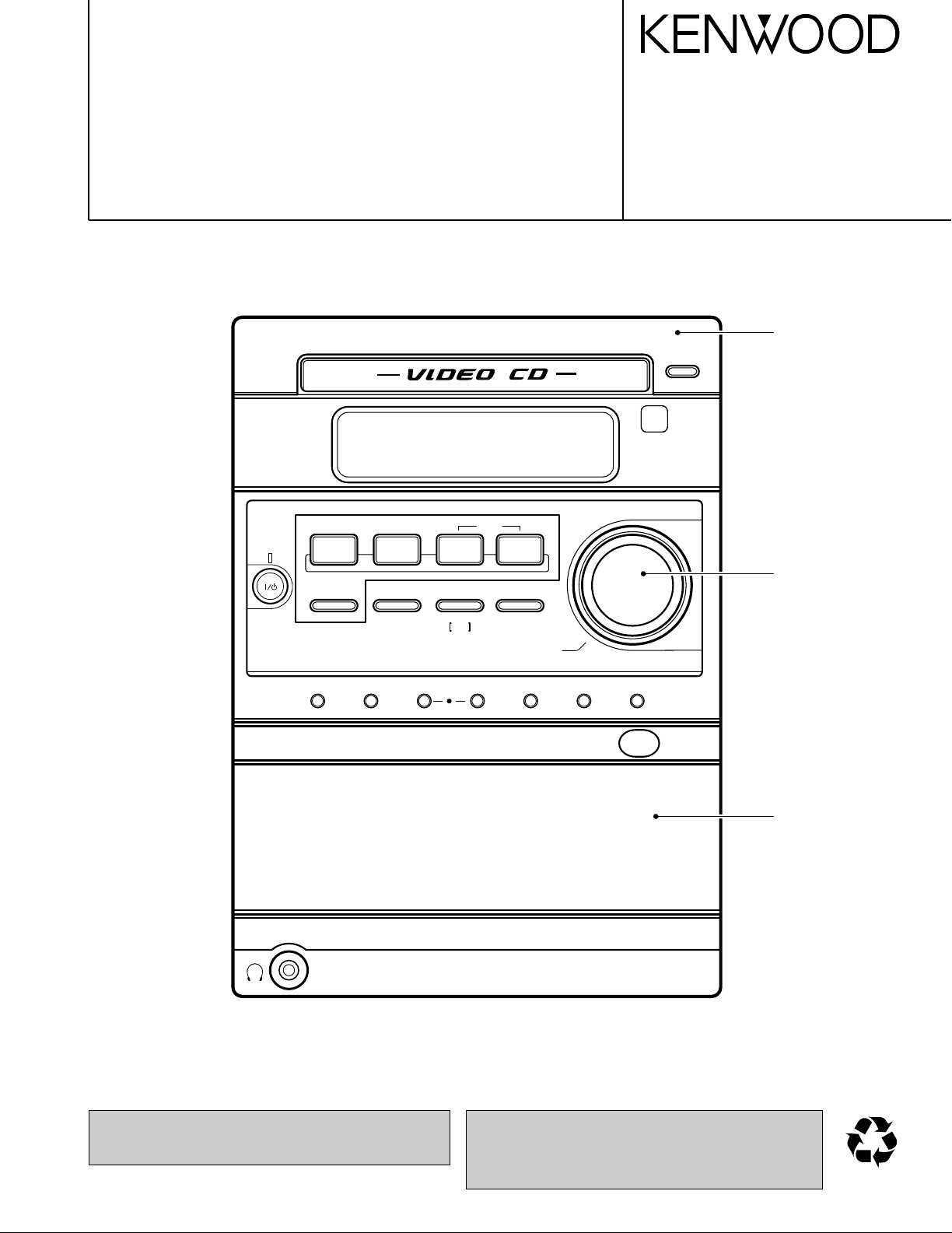
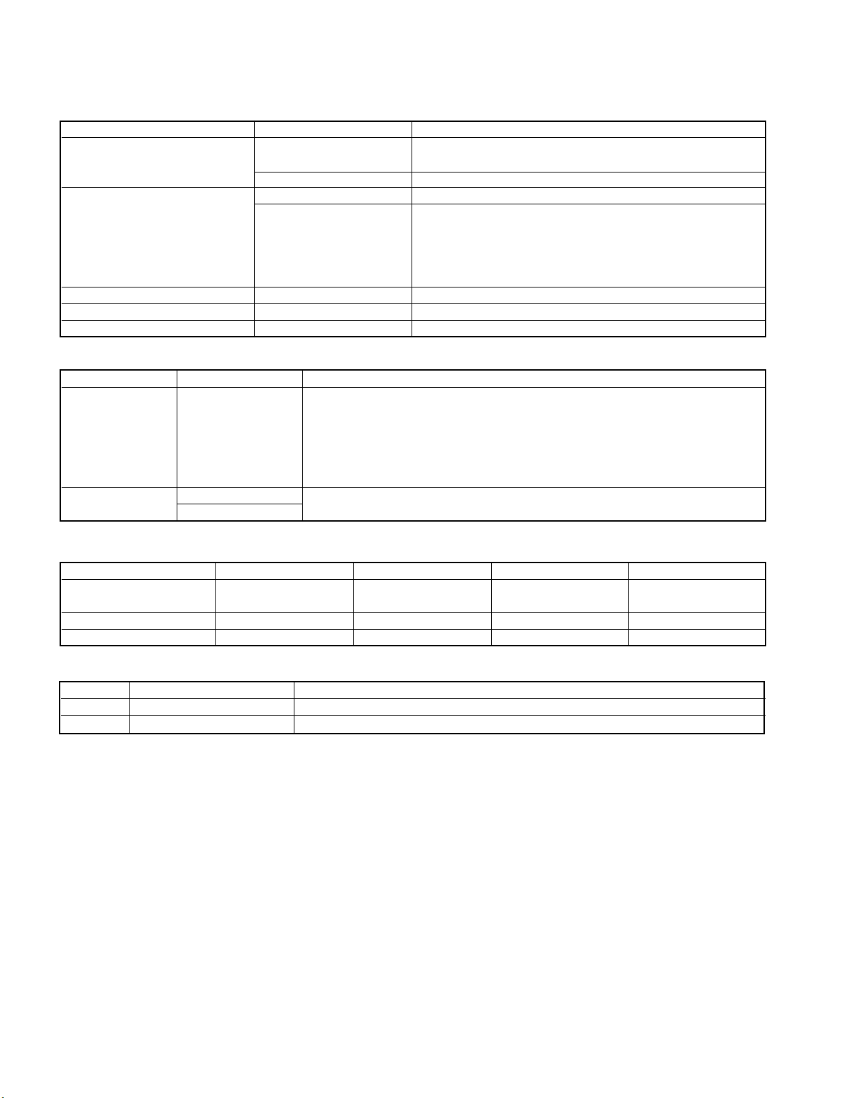
MINI HiFi COMPONENT SYSTEM
TAPE EQ.0menu set/ demo
push open
TAPE rec TAPE O.T.E.repeatsound
AUX
47
stop
¢
Tuning
Mode
FM/AM
TUNER
FM/AM
TUNER
remote
standby
/timer
6
CD
2
TAPE
3
volume / multi control
0
CD
volume / multi control
RXD-M33V
SERVICE MANUAL
(HM-353V)**
© 2001-6 PRINTED IN KOREA
B51-5738-00 (K/K) 404
Panel ass'y *
(A60-)
Knob
(K29-7907-04)
**Refer to page 2 if you want to know system configuration.
In compliance with Federal Regulations, following are reproduction of labels on, or inside the product relating to laser product safety.
Cassette holder ass'y *
(A53-)
* Refer to parts list on page 29.
KENWOOD-Crop. certifies this equipment conforms to DHHS
Regulations No.21 CFR 1040. 10, Chapter 1, subchapter J.
DANGER : Laser radiation when open and interlock defeated.
AVOID DIRECT EXPOSURE TO BEAM.

FM indoor antenna (1)
(T90-0877-05)
AM loop antenna (1)
(T90-0852-05)
Remote control unit (1)
(A70-1528-05): RC-M0304V
Battery cover(A09-1192-08)
Batteries (R6/AA) (2)
AC plug adaptor (1)
(E03-0115-05)
Use to adapt the plug on the power
cord to the shape of the wall outlet.
(Accessory only for regions where use
is necessary.)
Video Cord (1)
(E30-1427-05)
RXD-M33V
The marking this product has been
classified as Class 1. It means that there
is no danger of hazardous radiati
outside the product.
Operation to reset
The microcomputer may fall into malfunction (impossibility to operate, erroneous display, etc.) when the power
cord is unplugged while unit is ON or due to an external
factor. In this case, execute the following procedure to
reset the microcomputer and return it to normal condition.
Unplug the power cord from the power outlet then,
while holding the Power
key depressed, plug
the power cord again.
÷ Please note that resetting the microcomputer clears
the contents stored in and it returns to condition
when it left the factory.
CONTENTS / ACCESSORIES
Contents
CONTENTS / ACCESSORIES ................................... 2
EXTERNAL VIEW ........................................................3
DISASSEMBLY FOR REPAIR.....................................3
BLOCK DIAGRAM .......................................................4
CIRCUIT DESCRIPTION .............................................5
ADJUSTMENT ...........................................................11
Accessories
X
E
T
N
STOP
SELECT
POWER
CD
BAND
TUNER
TAPE EQ.
REC RETURN
TAPE
TUNING
P. CALL P. CALL
AUX
.
O.T.E.
TIMER
SET
PGM
TIME
CLEAR
ENTER
ON SCREEN
AUTO/MONO
PAL
NTSC
TONE
AUTO
VOLUME
SOUND
RANDOM
P
R
V
E
MUTE
SLEEP
REPEAT
MULTI PLEX
AUTO PBC
963
DIGEST
FREEZE
085
2
RC-M0304V
TIME
STEP
SEARCH
10
741
SLOW
RESUME
PC BOARD ................................................................12
SCHEMATIC DIAGRAM ............................................16
EXPLODED VIEW .....................................................27
PARTS LIST...............................................................29
SPECIFICATIONS .......................................Back cover
System configuration
SYSTEM MAIN UNIT DESTINATION SPEAKER COLOR
HM-353V-S RXD-M33V-S M LS-M33V-S SILVER
HM-353V-LM RXD-M33V-L M LS-M33V-LM BLUE
HM-353V-N RXD-M33V-N M LS-M33V-N GOLD
HM-353V-S RXD-M33V-S I LS-M33V-S SILVER
HM-353V-LM RXD-M33V-L I LS-M33V-LM BLUE
HM-353V-N RXD-M33V-N I LS-M33V-N GOLD
HM-353V-S(M2) RXD-M33V-S(M2) M2 LS-M33V-S SILVER
HM-353V-LM(M2) RXD-M33V-L(M2) M2 LS-M33V-LM BLUE
HM-353V-N(M2) RXD-M33V-N(M2) M2 LS-M33V-N GOLD
HM-353V-S RXD-M33V-S V LS-M33V-S SILVER
Cautions
CLASS 1
LASER PRODUCT
2
ANTENNA
+
-
L
-
+
R
FRONT
SPEAKERS
(6-16
Ω)
AM
GND
FM
75
Ω
AUX
OUTPUT
L
R
DIGITAL OUT OPTICAL
AUX
INPUT
L
R
VIDEO
OUT
AC 110120V
˜
AC 220240V
˜
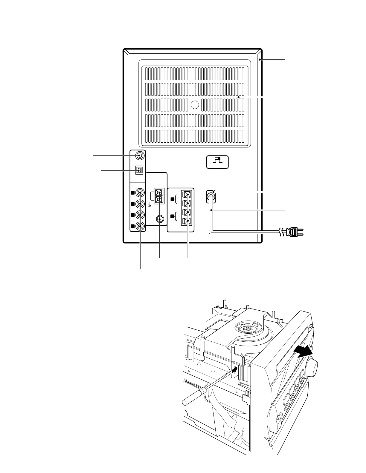
EXTERNAL VIEW / DISASSEMBLY FOR REPAIR
EXTERNAL VIEW
Pin jack
(E63-1010-05)
Oscillating module
(W02-1114-15)
RXD-M33V
Metallic cabinet *
(A01-)
Cover
(F07-1728-02)
AC power cord bushing *
(J42-)
Tuner ass'y *
(W02-)
Pin jack
(E63-1038-05)
DISASSEMBLY FOR REPAIR
How to open the CD tray when it does not
come out.
1. Insert a flat driver and so on to a square hole in the
mechanism as shown in the figure.
2. Push a rack gear in the direction of arrow.
(At this time, the tray comes out slightly frontward).
3. The tray can be opened with hand.
AC power cord *
(E30-)
Lock terminal board
(E70-0057-05)
* Refer to parts list on page 29.
3
LEVEL DIAGRAM
(X29- )
(X28- )
RXD-M33V
CD MECHA. UNIT
(X32-3880-20)
TUNER
FLAT
TAPE REC
TAPE PLAY
AUX IN
E.VOL
INPUT
VOL.
AMP
CD
AUX IN
E.VOL
X29,IC201
TONE
M61510FP
TUNER PACK
ERASE
REC/PLAY
HA12230NT
IC1
TRAP
BIAS
OSC
BIAS
D40-1716-05
DECK MECHA.
DIGITAL OUT
X29,A201
CD DSP
IC2
MAIN u-COM
X29,IC301
M30622MCAB30FP
REMOCON MODULE
A501
S518
ROTALY ENCODER
LED
KEY
FL DRIVER
IC501
FL
ED501
HNA-16MM30T
MPEG
DECODER
IC8
DAC
IC10 (1/2)
X29,IC1
POWER AMP
PROTECTION
HEADPHONES OUT
J1
D101
IC1
POWER AMP.
Q101
-35V
AVR
D120
IC102
+5V
AVR
D119
AVR
+9V
AVR
IC101
+9V
Q102
FIL
PRIMARY
RELAY
+5.4V
AVR
IC1X00,
D1
T1
AUX OUT
AUX OUT
D510,D511
TIMER/STANDBY
IC4
SELECTORTV ENCODER
IC10 (2/2)
VIDEO
IC1
RF AMP
MOTOR
IC3
DRIVER
LOADING
CD MECHA.
D40-1714-05
LM4766T
SURROUND CONTROLLER
TRANSFORMER
MAIN
OUT
AM 0dB=180mV
FM 0dB=600mV:75kDEV.
0dB=1.2V:1kHz
0dB=580mV(315Hz)
300mV
VOL
300mV
+23.8dB
TUNER
CD -6dB
0
INPUT VOL.
AUX
TAPE
REF.-4dB
0
0 to -14dB(VARIABLE)
SELECTOR
INPUT VOL.
MAIN VOL.1
0 to -16dB
LOUDNESS
+-10dB
BASS.MID.TRE
MAIN VOL.2
0 to -64dB.INFINITY.
J202
AM
FM
A.OUT
PB AMP
REC AMP
BIAS ADJ.
VR1.2
PLL DO
SA CE
SA DATA
SA CLK
SD
ST
REC/PLAY
BEAT CANCEL
CRO2-SW
PHOTO
SOL
REC-R
REC-F
PACK-SW
PLAY-SW
DATA
CLK
CE
A.MUTE ON/STANDBY
++
-B
+B
+
+
FL DRIVER
+
LED
FL DRIVER
PRE.AMP/TUNER
+
TUNER
CASSETTE DECK
CD
K1
ON/OFF
+
u-COM
STND-BY LED
TACT KEY
AC IN
REMOCON. MODULE
BACK UP CIRCUIT
K1
A/B-2
A/B-1 B1/2
J203
X29,J201
VCD
4
RXD-M33V
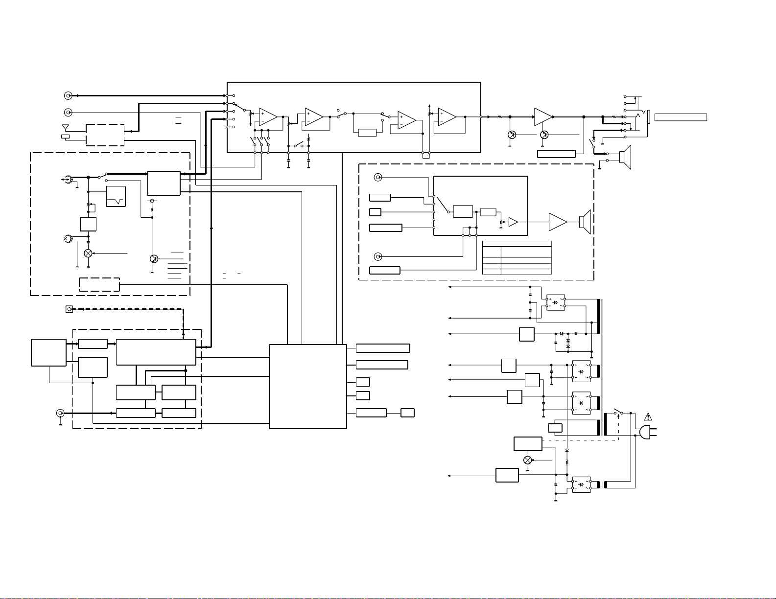
BLOCK DIAGRAM
RXD-M33V
CIRCUIT DESCRIPTION
1. Initializing
1-1 Initialization Method
• While pressing the [POWER] key, turn the AC on.
1-2 Initialization Operation
• During the initial operation, the display shows "INITIALIZE" and after that it will be returned to standby
condition.
• If any mechanisms error occurred, the error indication
is displayed as "ERR" in the display.
1-3 Mechanism Initializations
1 CD Mechanism
• If a mechanism error occurred, the error indication is
displayed as "C ERR" in the display.
2 Deck Mechanism
• If a mechanism error occurred, the error indication is
displayed as "X ERR" in the display.
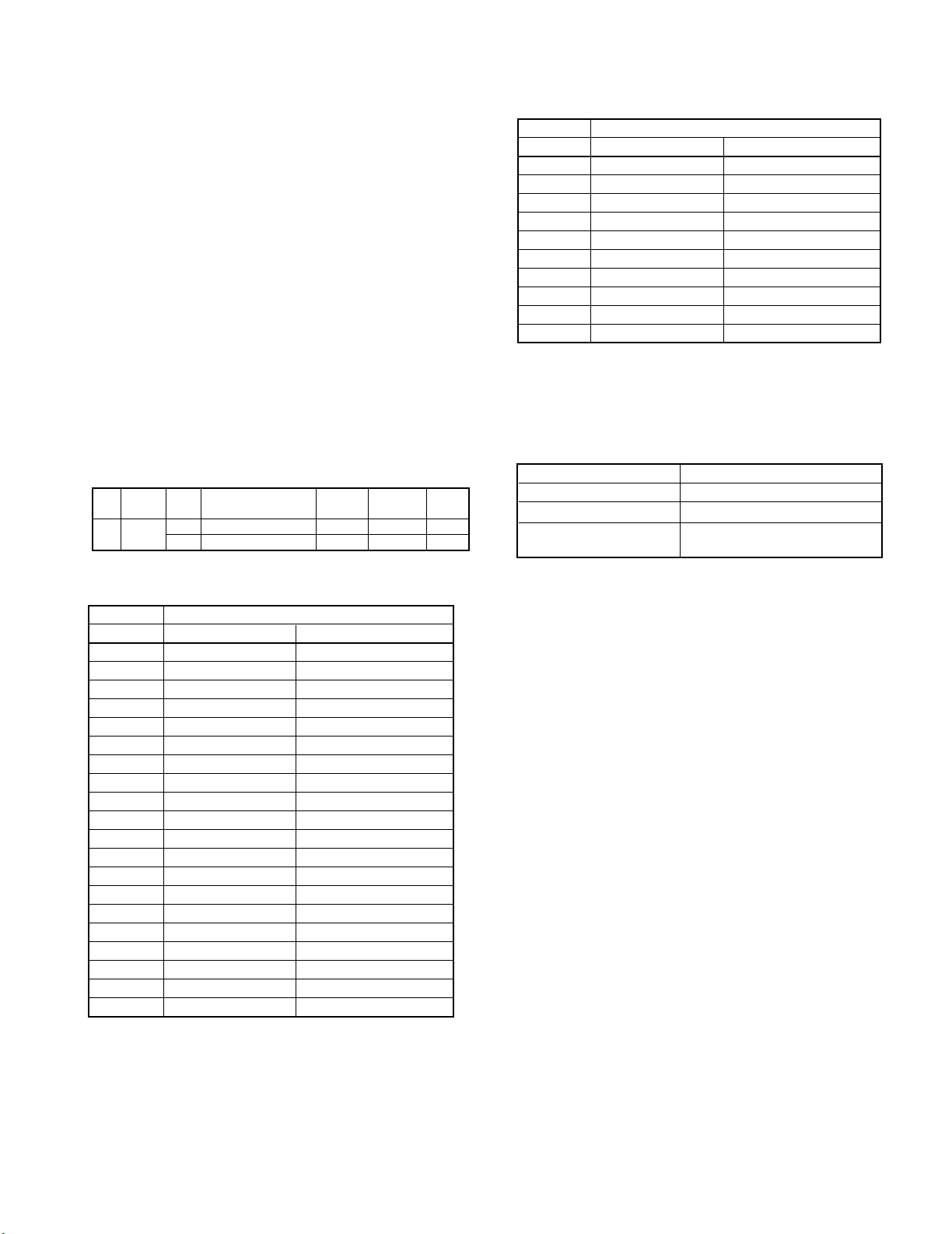
2. Tuner Destination
Destin-
Set
ation Range Space
M K2 FM 87.5MHz~108.0MHz 100kHz +10.7MHz 25kHz
Receiving Frequency Channel
Band
AM 530kHz~1610kHz 10kHz +450kHz 10kHz
IF RF
Frequency
P.CH M,M2,I Type K2(M,M2 Type)
21 AM 531kHz AM 530kHz
22 FM 87.50MHz FM 87.50MHz
23 FM 87.50MHz FM 87.50MHz
24 FM 87.50MHz FM 87.50MHz
25 FM 87.50MHz FM 87.50MHz
26 FM 87.50MHz FM 87.50MHz
27 FM 87.50MHz FM 87.50MHz
28 FM 87.50MHz FM 87.50MHz
29 FM 87.50MHz FM 87.50MHz
30 FM 106.0MHz FM 106.0MHz
4. Test Mode
4-1 Setting method of the Test Mode
• While pressing the "below each" key in the table, turn
the power switch on.
TEST MODE SETTING METHOD
CD MODE CD PLAY key+AC ON
DECK MODE TAPE PLAY key (3) +AC ON
✽ FCT & SUB CLOCK MENU key + AC ON
OSC DIAGNOSIS
3. Tuner Preset Frequency
Frequency
P.CH M,M2,I Type K2(M,M2 Type)
1 FM 98.30MHz FM 98.30MHz
2 FM 98.00MHz FM 87.50MHz
3 FM 87.50MHz FM 89.10MHz
4 FM 89.10MHz FM 108.0MHz
5 FM 108.0MHz FM 90.00MHz
6 FM 90.00MHz FM 87.50MHz
7 FM 87.50MHz FM 87.50MHz
8 FM 87.50MHz FM 87.50MHz
9 AM 1602kHz AM 1610kHz
10 AM 999kHz AM 1000kHz
11 AM 630kHz AM 630kHz
12 AM 1440kHz AM 1440kHz
13 FM 106.0MHz FM 106.0MHz
14 AM 531kHz AM 530kHz
15 FM 87.50MHz FM 87.50MHz
16 FM 98.00MHz FM 98.00MHz
17 FM 98.50MHz FM 98.50MHz
18 FM 87.50MHz FM 87.50MHz
19 AM 990kHz AM 990kHz
20 FM 97.70MHz FM 97.40MHz
✽ The oscillation diagnosis (existence of oscillation and
measurement of period) of a sub clock is performed
before the test mode is entered. If the diagnosis
result is OK, the system enters the test mode.
If the diagnosis result is NG, the oscillation of the sub
clock is diagnosed again. If the result is OK, the system enters the test mode. If the diagnosis result is
continuously NG 5 times, the system stops with
"ERR1" and "ERR2" displayed.
4-2 Cancel of the test mode
• By turning the AC off, the system is initialized and
the test mode is canceled.
• Cancel the test mode only if the power switch is
turned off.
4-3 Contents of the Test Mode
• The muting during mode selection is not controlled
in the test mode.
• During the test mode, it can be operated in a special
manner that is different from an ordinary operation
by using the keys on the main body, specifically as
shown in the following tables.
5
RXD-M33V
4-4 CD Test Mode
KEYS DISPLAY OPERATION
CD-PLAY/PAUSE 05 ✽ ✽ : ✽ ✽ Tracking-servo on.
(Cyclically changed the mode ( ✽✽: ✽✽ )Time Display
05 and 03 by pressing the key.) 03 Tracking-servo off.
CD STOP 01 --:-- Stop the CD operation.
(Cyclically changed in the 07 FG/FE FG value/FE value
stop mode only.) 08 FB/FO FBAL value/FO value
SKIP UP Ex.01~02 • CD track number up.
SKIP DOWN Ex.02~01 • CD track number down.
SKIP UP/SKIP DOWN Usual Indication • Play the last track number in the stop mode.
4-5 Deck Test Mode
KEYS DISPLAY OPERATION
TAPE REC Usual Indication If the REC/ARM key is pressed, during the 4seconds REC operation, the
MENU T-EQ ON Changeover the EQ. On/off cyclically.
T-EQ OFF
✽ Mechanism half switches indication
The mechanism half switches status are indicated as "blank" or "E" in the display.
8th Dot(Display) 1st figure 2nd figure 3rd figure 4th figure
Mechanism FWD REC Inhibit RVS REC Inhibit CrO2(TYPE¿) Cassette Half
Half Switch Detection SW Detection SW Detection SW Detection SW
ON Blank Blank Blank Blank
OFF E E E E
CIRCUIT DESCRIPTION
Adjustment value/mean value
09 TG/TE TG value/TE value
10 TB/TO TBAL value/TO value
• 4 Seconds Recording
If the REC/ARM key is pressed, the system record for 4 seconds.
Then, it rewinds to the REC starting position and plays back automatically.
system records further for 4 seconds, then returns to the starting position
of the first 4 seconds REC operation and plays back.
4-6 FCT(Factory) Test Mode
KEYS DISPLAY OPERATION
REPEAT Usual Indication • The tray opens while holding down the repeat key.
SOUND Usual Indication • The tray closes while holding down the sound key.
6
RXD-M33V
CIRCUIT DESCRIPTION
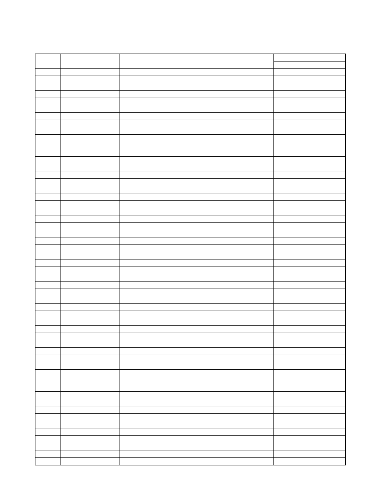
5. Port Description of Microcomputer
Port No. Port Name I/O Description
1 SEL DT O Data output to surround controller.
2 TYPE I Discrimination of tuner destination.
3~7 NC - Not Connected.
8 BYTE - Connected to ground.
9 CN VSS - Connected to ground.
10 XC IN I Timer clock input (32.768kHz).
11 XC OUT O Timer clock output (32.768kHz).
12 RESET I Reset signal input for microcomputer. Normal Reset
13 V OUT O Main clock output (10MHz).
14 VSS - Connected to ground.
15 X IN I Main clock input (10MHz).
16 VCC(BU) - Microcomputer power supply (+5v).
17 NMI Connected to VCC.
18 REMOCON I Remote control signal input.
19 ESS ST I Interrupt for ESS/ESS start to transmit
20 ESS ST I Interrupt for ESS/ESS finish to transmit
21 CE I Back up detection input. AC ON AC OFF
22~25 NC - Not Connected.
26 HP DET I Detection port for headphones jack. H/P IN H/P OUT
27 CD POWER O CD DSP power on/off changeover control. ON OFF
28 ESS CLK I Clock input from ESS.
29 ESS DIN I Data input from ESS.
30 ESS DO O Data output to ESS.
31 NC - Not Connected.
32 SP RLY O On/off control port for speaker relay. ON OFF
33 AMUTE O Audio mute control. Mute OFF Mute ON
34 POWER O Power relay control. ON OFF
35 FL DATA O Data output to FL dot driver.
36 NC - Not Connected.
37 FL CLK O Clock output to FL dot driver.
38 FL CE O CE output to FL dot driver. Disable Enable
39 FL RST O Reset output to FL dot driver. Normal Reset
40 LED POWER O Timer led (green) control port. OFF ON
41 LED STBY O Standby led (red) control port. OFF ON
42,43 ENC 1,2 I Volume encoder (A/B) input.
44~46 NC - Not Connected.
47 CLOSE O Control port of CD tray motor. ON OFF
48 OPEN O Control port of CD tray motor. ON OFF
49 CLOSE SW I Input port of close switch for CD tray. OFF ON
50 OPEN SW I Input port of open switch for CD tray. OFF ON
51 FAN O Control port to fan motor. ON OFF
52 A/B-1 O Deck recording mute & head select control 1.
53 A/B-2 O Deck recording mute & head select control 2. Recording
54 Bø/¿ O Control port of recording equalizer for deck. TYPE ¿
55~61 NC - Not Connected.
62 VCC(BU) - Connected to VCC.
63 NC - Not Connected.
64 VSS - Connected to ground.
65 PLAY SW I Detection switch input of head position for deck. OFF ON
66 CrO2 SW I Detection switch input of CrO2 tape for deck. TYPE ¿ TYPEø
67 HALF SW I Cassette half switch input. OFF ON
68 REC F SW I Deck forward recording switch input. OFF ON
69 CPM O Control port of capstan motor for deck. ON OFF
Active
HL
Except
Recording
7
RXD-M33V
CIRCUIT DESCRIPTION
Port No. Port Name I/O Description
70 REC R SW I Deck reverse recording switch input. OFF ON
71 SOL O Control port of solenoid for deck. ON OFF
72 LMUTE O Deck line mute control. Mute ON Mute OFF
73~75 NC - Not Connected.
76 NOR O Switching port of bias (NOR/CrO2) for deck. TYPEø
77 BIAS O Control port of bias on/off for deck. ON OFF
78 R/P O Deck recording & playback changeover.
79 BEAT C O On/off control port of beat cancel for deck. ON OFF
80 MUTE O Tuner mute control. Mute OFF Mute ON
81 PLL CE O PLL IC chip enable output.
82 PLL DT O PLL IC data output.
83 PLL CLK O PLL IC clock output.
84 PLL DO I PLL IC data input.
85 SD I SD detection signal input. NO Tuned Tuned
86 ST I Stereo detector input. Mono Stereo
87 EEP SCL - Unused.
88 EEP SDA - Unused.
89 S LEVEL I Unused.
90 FAN LEVEL I Level detection port for fan control.
91 CD PROTECT I Detection port for CD protection.
92 PROTECT I Detection port for protection. Normal
93,94 KEY2,KEY1 I A/D key (1,2) input.
95 TH. SENS I Not Connected.
96 AVSS - Connected to ground.
97 PH I Deck reel pulse input.
98 VREF - A/D reference voltage input.
99 AVCC(BU) - Power supply input (+5V).
100 SEL CLK O Clock output to surround controller
REC/ARM /
REC PAUSE
Active
HL
Others
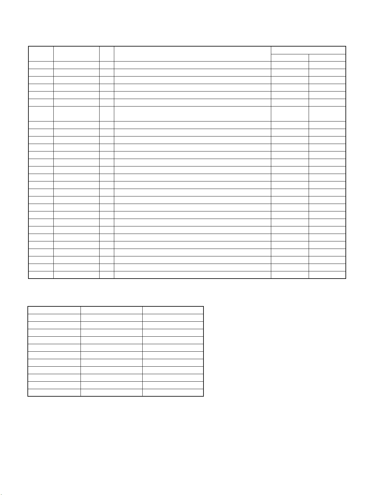
6. Key Matrix
Input Voltage Key 1 Key 2
(V) Pin 93 Pin 94
0.00~0.39 POWER SKIP UP
0.43~1.14 AUX SET/DEMO
1.18~1.69 SKIP DOWN MENU
1.71~2.18 STOP TAPE EQ
2.21~2.66 TAPE FWD TAPE REC
2.70~3.04 TAPE RVS OTE
3.08~3.45 CD REPEAT
3.49~3.84 TUNER SOUND
3.88~4.41 CD OPEN/CLOSE -
4.43~4.80 KEY OFF KEY OFF
✽ The input voltage value : for 4.8 [ v ] in a standard voltage.
8
RXD-M33V
CIRCUIT DESCRIPTION
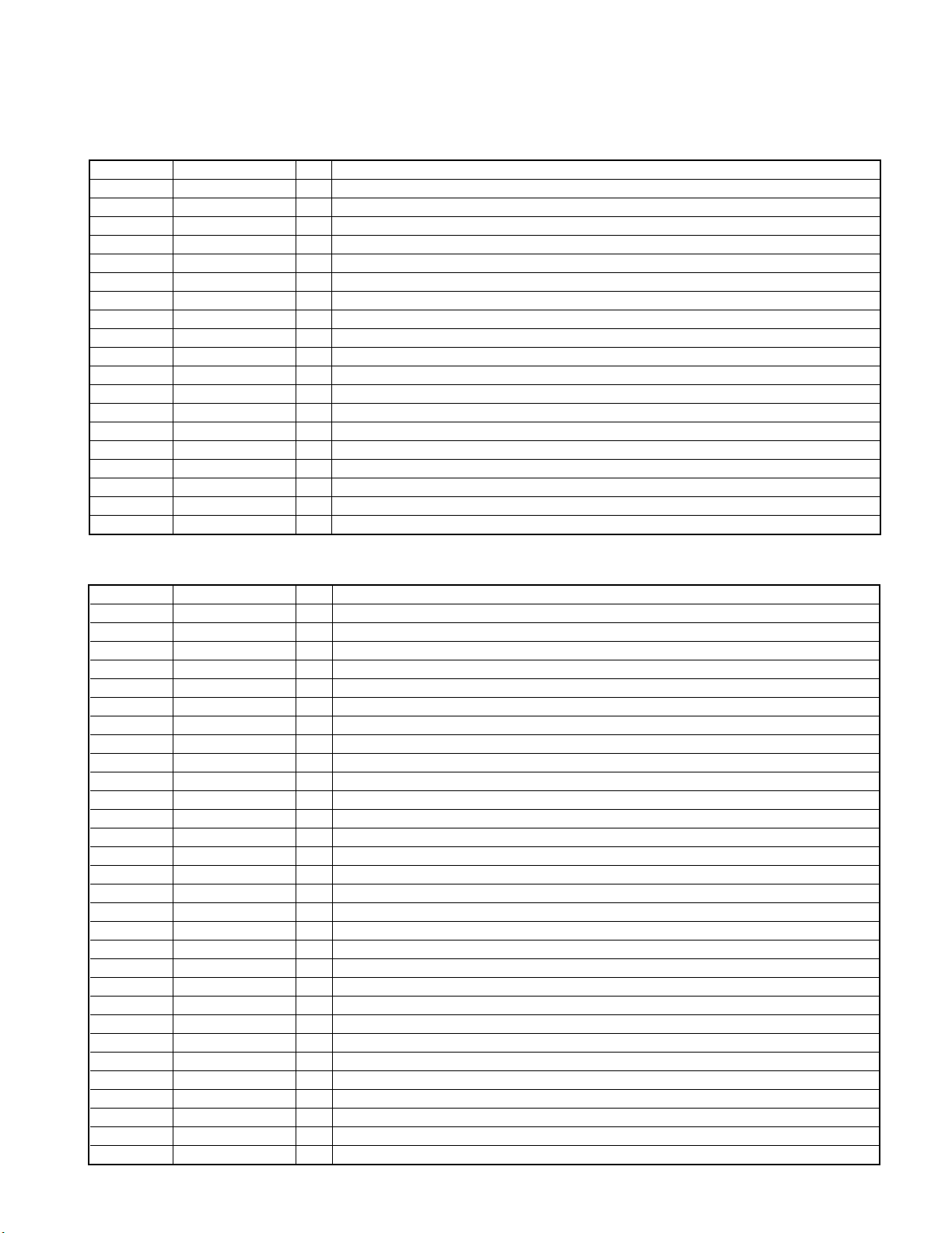
7. Port Description of IC
7-1 Sound Controller with Surround IC(X29, IC201)
Port No. Port Name I/O Description
1 REF IN I Input pin of the reference amplifier.
2 REF OUT O Output pin of the reference amplifier.
3,40 CD I Input pin of the CD.
4,39 NC I Unused.
5,38 TUN I Input pin of the TUNER.
6,37 TAPE I Input pin of the Tape play.
7,36 AUX IN I Input pin of the CD.
8,35 TA REC O Output pin of the input volume 1 and 2.
9,34 AUX OUT I Input pin of the volume input selector A1 and A2/Output pin of the REC-C1 and 2.
10,33 VSEL A OUT1,2 - Capacitor connection pin for the volume changing noise reduction.
11,32 LOUDNESS - Frequency characteristic setting pin in the loudness part.
12,31/13,30 E.. BASS - Frequency characteristic setting pin in the tone control (Bass).
14,29/15,28 E.. BASS - Frequency characteristic setting pin in the tone control (Mid).
16,27 TRE - Frequency characteristic setting pin in the tone control (Treble).
17,26 VSEL B OUT1,2 O Output pin of the volume input selector B1and B2.
18,25 VOL IN1.2 I Input pin of the main volume.
19,24 VOL OUT1,2 O Output pin of the main volume.
20 VCC - Power supply (+5.0V)
21 DATA I Input pin of the serial data.
7-2 Port Function of PB/REC Equalizer System IC(X28,IC1)
Port No. Port Name I/O Description
1 VREF - Reference voltage.
2 GND - Ground port.
3 BIN-R I PB B deck right channel input.
4 AIN-R I PB A deck right channel input.
5 PBNF-R - PB EQ. feed back.
6 PBEQ-R O Equalizer right channel output (70u).
7 EOUT-R O Equalizer right channel output (120u).
8 TAI-R I Tape right channel input.
9 PBOUT-R O PB right channel output.
10 MAOUT O MS amplifier output.
11 MAI I MS amplifier input.
12 IREF I Equalizer reference current input.
13 RIN-R I Rec equalizer right channel input.
14 RIP O NAB output.
15 ROUT-R O Rec equalizer right channel output.
16 ROUT-L O Rec equalizer left channel output.
17 VCC - Power supply.
18 RIN-L I Rec equalizer left channel input.
19 MUTE I Mode control input.
20 A120/70 I Mode control input.
21 A/B I Mode control input.
22 B I/I I I Mode control input.
23 PBOUT-L O PB left channel output.
24 TAI-L I Tape left channel input.
25 EQOUT-L O Equalizer left channel output (120u).
26 PBEQ-L O Equalizer left channel output (70u).
27 PBNF-L - PB EQ. feed back.
28 AIN-L I PB A deck left channel input.
29 BIN-L I PB B deck left channel input.
30 REC-RST - Rec return.
9
RXD-M33V
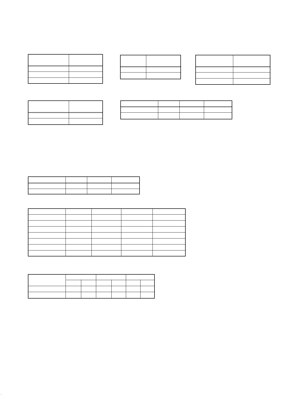
8. Port Logic
• Cassette Deck Reel Pulse (X29, IC301)
Input Voltage (V)
(Pin 97)
0.00~1.93 LOW
1.95~2.91 -
2.92~4.80 HIGH
• Thermal Sensor (X29, IC301)
Input Voltage (V)
(Pin 97)
0.00~2.49 ON
2.51~4.80 OFF
2Timing Chart
M + : Motor control for CD tray open direction HIGH : Motor ON
M - : Motor control for CD tray close direction HIGH : Motor ON
OPEN SW : Tray open detection switch LOW : Switch ON
CLOSE SW : Tray close detection switch LOW : Switch ON
Logic
Protection
CIRCUIT DESCRIPTION
• Voltage Protection (X29, IC301)
Port Logic
(Pin 92)
LOW OFF
HIGH ON
• CD Tray Mechanism Control
1 Port Logic
Loading Motor OPEN CLOSE BRAKE
M + HIGH LOW HIGH
Protection
M - LOW HIGH HIGH
• CD Protection (X29, IC301)
Input Voltage (V)
(Pin 91)
0.00~1.50 ON
1.51~3.49 OFF
3.50~4.80 ON
Protection
• Cassette Mechanism Control
✽ A/B Low Mid High
✽ A/B-1 L H H
✽ A/B-2 L L H
X29, IC301
Deck Mode R/P(Pin78) BIAS(Pin77) A/B-1(Pin52) A/B-2(Pin53)
STOP L L L L
PLAY L L L L
FF L L L L
RWD L L L L
REC H H H H
ARM H H H L
REC PAUSE H L H L
• PB/REC AMP (X28, IC1)
PLAY REC ARM
NOR CrO2 NOR CrO2 NOR CrO2
A/B (Pin 21) L L H H M M
Bø/¿ (Pin 22) L H L H L H
✽ A/B : Pin 21(X28, IC1)
✽ A/B-1 : Pin 52 (X29, IC301)
✽ A/B-2 : Pin 53 (X29, IC301)
10
 Loading...