

Page 1

7-Inch WIDE SCREEN MONITOR-RECEIVER
KVT-M700
INSTRUCTION MANUAL
Take the time to read through this instruction manual.
Familiarity with installation and operation procedures will help you
obtain the best performance from your new monitor-receiver.
For your records
Record the serial number, found on the back of the unit, in the spaces
designated on the warranty card, and in the space provided below. Refer to
the model and serial numbers whenever you call upon your KENWOOD dealer
for information or service on the product.
Model KVT-M700 Serial number
© PRINTED IN JAPAN B64-2134-00/01 (K)(DT)
Page 2

Contents
Before Use ............................................................4
• Safety Precautions
• About RDS
Monitor Control Function....................................5
• Opening the Monitor
• Closing the Monitor
• Power Off
• Switching the Monitor’s Picture
• Switching the Screen Mode
• Switching the AV Output
• Switching to the Angle/Screen Control Screen
• Turning the Monitor Picture Off
Angle Control Screen
• Angle Control Screen
• Adjusting the Angle Position [ANGLE]
• Adjusting the Slide Position [SLIDE]
• Automatic Open/Close [AUTO OPEN-CLOSE]
• Switching to the Screen Control Screen
• Exit the Angle Control Screen
Screen Control Screen
• Adjusting the Picture Quality
• Auto Dimmer [DIM]
• Switching to the Angle Control Screen
• Exit the Screen Control Screen
Menu Function .....................................................8
Menu Screen
• Selecting the Menu Screen
• Selecting the Setup Menu Screen
• Selecting the Sound Control Menu Screen
• Selecting the External Display Control Screen
• Selecting the Sensor Box Control Screen
• Exit the Menu Screen
Setup Function .....................................................9
Setup Menu Screen
• Selecting the Touch Panel Adjustment Screen
• Selecting the AV Setup Screen
• Selecting the Clock Adjustment Screen
• Selecting the System Setup Screen
• Selecting the Code Security Screen
Clock Adjustment Screen
• Synchronize Clock [SYNC]
• Manual Clock Adjustment [CLOCK]
• Exit the Clock Adjustment Screen
Code Security Screen
• Security Code
• Exit the Code Security Screen
Touch Panel Adjustment Screen
• Adjusting the Touch Position
AV Setup Screen
• Setting the AV IN-1 Mode [AV-IN1]
• Setting the AV IN-2 Mode [AV-IN2]
• Setting the RGB Mode [RGB]
• Setting the the AV Output Mode [AV-OUT]
• Exit the AV Setup Screen
System Setup Function .....................................12
System Setup Screen
• Touch Sensor Tone [BEEP]
• On Screen Display [ON SCREEN]
• Disabled System Indicator [DSI]
• Switching the Setup Screen -1 and 2
• Selectable Illumination [KEY ILLUMI]
• Key Indicator Color [KEY INDICATOR]
• Navigation Announcement [NAV INTERRUPTION]
• Sound Attenuate [NAV GUIDE]
• Exit the System Setup Screen
Sound Control Function ....................................14
Sound Control Menu Screen
• Selecting the Audio Setting Screen
• Selecting the System Es Setting Screen
• Selecting the Speaker Select Screen
• Selecting the Tone Control Screen
Audio Setting Screen
• Balance and Fader [BAL/FAD]
• Loudness [LOUD]
• B.M.S. (Bass Management System) [AMP BASS]
• B.M.S. Frequency Offset [AMP FREQ]
•Volume Offset
• Switching the Audio Setting Screen -1 and 2
•System Q [SYSTEM Q]
• System Q Ex [SYSTEM QEx]
• Dual Zone System [2 ZONE]
• Exit the Audio Setting Screen
Speaker Select Screen
• Speaker & Woofer Setting
• Exit the Speaker Select Screen
Tone Control Screen
• Tone Control (System QEx set to OFF)
• Tone Control (System Q Es set to ON)
• Switching to the Tone Control Screen -1 and 2
• Exit the Tone Control Screen
System Es Setting Screen
• System Es
• Exit the System Es Setting Screen
Source Control Function
(Common operation) .........................................18
• Displaying the On Screen Control
• Changing the Audio Source Mode
• Volume
•Attenuator
• Loudness
• Non-fading Output
• Switching to the Menu Screen
• Changing the Function Buttons
• Changing the Background Mode for the Control Screen
• TEL Mute
FM/AM Tuner Control Function .......................20
• Selecting the FM band
• Selecting the AM band
• Tuning
• Station Preset Memory
• Preset Tuning
• Auto Memory Entry
• Seek Mode
• CRSC
• Traffic Information
• Switching Display
• Switching to the FM/AM List Screen
• Switching to the PTY Search Screen
• Switching to the Name Set Screen
• FM/AM List Screen
• PTY Search Screen
2
Page 3

AV Control Function ..........................................23
• Selecting the On Screen Control
• Selecting the Preset Band TV1 and TV2
• Selecting the Video Input
• Seek Mode
• Selecting the Channel
• Station Preset Memory
• Auto Memory Entry
• Recalling a Preset Station
• Switching to the TV List Screen
• Switching to the Name Set Screen
• TV List Screen
CD Player Control Function...............................25
• Pause and play
• Fast Forwarding and Reversing
• Track Search
• Track Repeat
• Track Scan
• Random Play
• Switching Display
• Switching to the Name Set Screen
Disc Changer Control Function.........................26
• Pause and play
• Fast Forwarding and Reversing
• Track Search
• Album Search
• Track Repeat
• Album Repeat
• Track Scan
• Random Play
• Magazine Random Play
• Switching Display
• Switching to the Disc List Screen
• Switching to the Name Set Screen
• Disc List Screen
Name Set Function ............................................28
Station Name Preset (SNPS)/
Disc Name Preset (DNPS)
Other Option Control Function.........................29
Weather Band Tuner Control
• Selecting the Channels
SIRIUS Tuner Control
• Selecting the Preset Band
• Selecting the Channel
• Station Preset Memory
• Seek Mode
• Channel Scan
• Channel Search
• Switching to the Information Screen
External Display Control
• Switching the Display
• Exit the External Display Control Screen
Sensor Box Control
• Setting the Menu
• Exit the Sensor Box Control Screen
Remote Control Function ..................................34
Installation ..........................................................36
Troubleshooting Guide......................................43
Specifications .....................................................46
The illustrations of the display and the panel appearing in this manual are examples used to explain more clearly how the
controls are used. Therefore, what appears on the display in the illustrations may differ from what appears on the display
on the actual equipment, and some of the illustrations on the display may represent something impossible in actual
operation.
3
Page 4
Before Use
Safety Precautions
2WARNING
To prevent injury and/or fire, take the following
precautions:
• Ensure that the unit is securely installed. Otherwise it
may fly out of place during collisions and other jolts.
• When extending the ignition, battery or ground wires,
make sure to use automotive-grade wires or other cables
with an area of 0.75mm2(AWG18) or more to prevent
wire deterioration and damage to the wire coating.
• To prevent short circuits, never put or leave any metallic
objects (e.g., coins or metal tools) inside the unit.
• If the unit starts to emit smoke or strange smells, turn off
the power immediately and consult your Kenwood dealer.
• Do not touch the liquid crystal fluid if the LCD is damaged
or broken due to shock. The liquid crystal fluid may be
dangerous to your health or even fatal.
If the liquid crystal fluid from the LCD contacts your body
or clothing, wash it off with soap immediately.
2CAUTION
To prevent damage to the machine, take the
following precautions:
• Make sure to ground the unit to a negative 12V DC power
supply.
• Do not open the top or bottom covers of the unit.
• Do not install the unit in a spot exposed to direct sunlight
or excessive heat or humidity. Also avoid places with too
much dust or the possibility of water splashing.
• Do not subject the faceplate to excessive shock, as it is a
piece of precision equipment.
• When replacing a fuse, only use a new one with the
prescribed rating. Using a fuse with the wrong rating may
cause your unit to malfunction.
• To prevent short circuits when replacing a fuse, first
disconnect the wiring harness.
• Do not use any screws except for the ones provided. The
use of improper screws might result in damage to the
main unit.
• You cannot view video pictures whilst the vehicle is
moving. To enjoy TV/video pictures, find a safe place to
park and engage the parking brake.
NOTE
• If you experience problems during installation, consult
your Kenwood dealer.
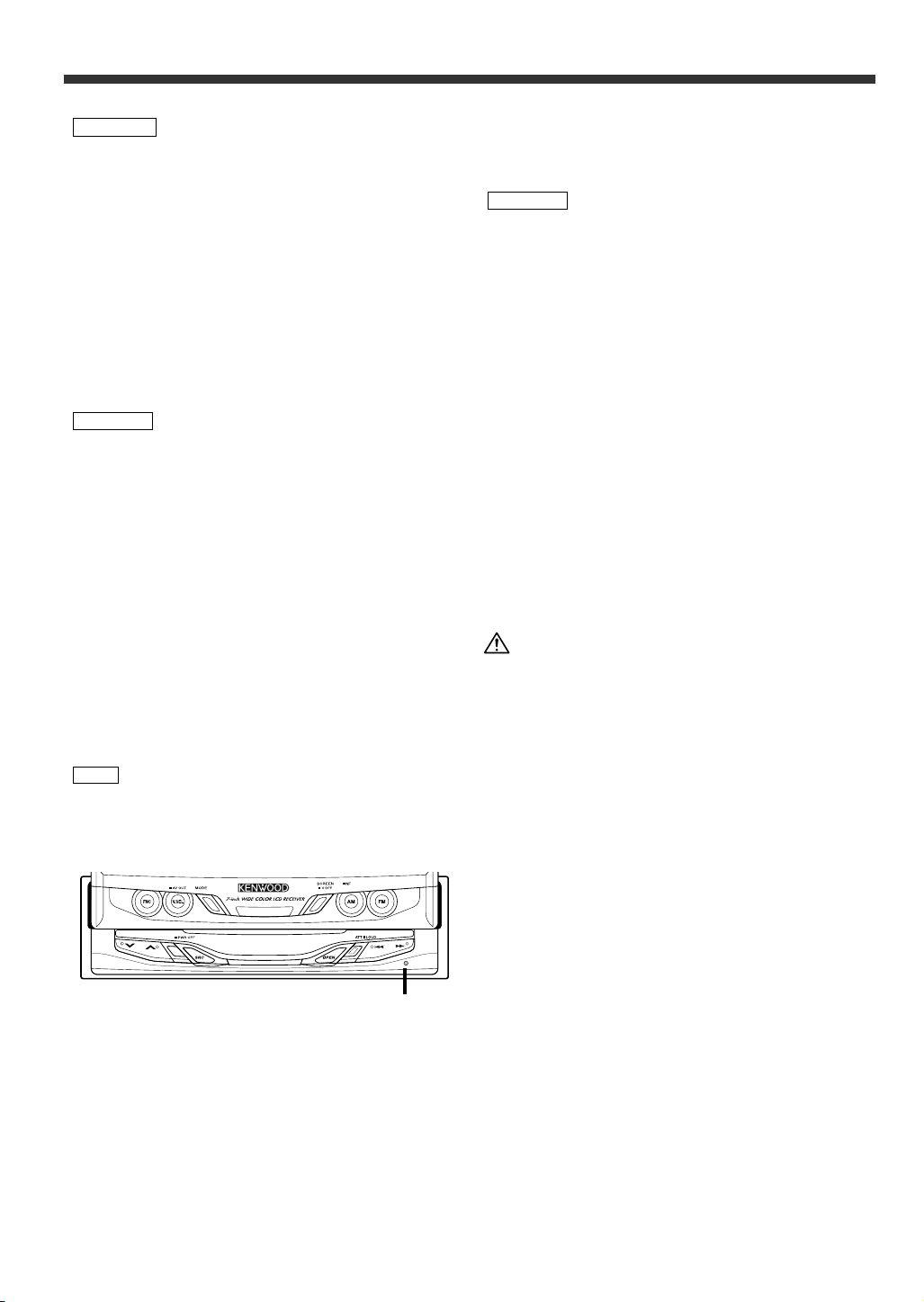
• If the unit does not seem to be working right, try pressing
the reset button first. If that does not solve the problem,
consult your Kenwood dealer.
Reset button
• We recommend the use of the Security Code function (see
p. 10) to prevent theft.
Cleaning the Unit
If the faceplate of this unit is stained, wipe it with a dry
soft cloth such as a silicon cloth.
If the faceplate is stained badly, wipe the stain off with a
cloth moistened with neutral cleaner, then wipe neutral
detergent off.
2CAUTION
Applying spray cleaner directly to the unit may affect its
mechanical parts. Wiping the faceplate with a hard cloth
or using a volatile liquid such as thinner or alcohol may
scratch the surface or erases characters.
Screen brightness during low temperatures
When the temperature of the unit falls such as during
winter, the liquid crystal panel's screen will become
darker than usual. Normal brightness will return after
using the monitor for a while.
IMPORTANT INFORMATION
About the disc changer/CD player to be
connected:
To connect a disc changer having the "O-N" switch to this
unit, set the "O-N" switch to "N".
To connect a disc changer having no "O-N" switch to this
unit, the converter cord CA-DS100 and/or switching
adapter KCA-S210A are required as options.
A disc changer doesn't work when it is connected
without using these options.
If a model with no "O-N" switch is connected, some
unavailable functions and information that cannot be
displayed are generated.
Note that none of the KDC-C100, KDC-C302, C205, C705,
and non-Kenwood CD changers can be connected.
You can damage both your unit and the CD changer if you
connect them incorrectly.
FCC WARNING
This equipment may generate or use radio frequency
energy. Changes or modifications to this equipment may
cause harmful interference unless the modifications are
expressly approved in the instruction manual. The user
could lose the authority to operate this equipment if an
unauthorized change or modification is made.
About RDS
RDS (Radio Data System)
RDS is a service used by radio stations to transmit data
outside normal radio broadcast signals.
When an RDS station is received, you can immediately
find out what kind of data is being transmitted by looking
at the program service name, which appears in the
display after the frequency.
The RDS indicator turns on when an RDS station is being
received.
Alarm
When an emergency transmission (announcing disasters,
etc.) is made, the current function will be interrupted to
allow the warning to be received under the following
conditions:
during tuner reception, or when the Traffic Information
function is turned on.
4
Page 5
Monitor Control Function
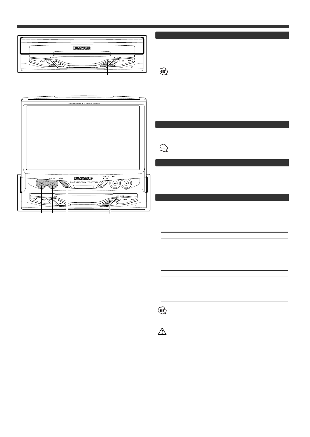
OPEN
Opening the Monitor
1 Set the vehicle’s parking brake.
2 Press the [OPEN] button.
The monitor will open.
• The gear shift lever or other parts may interfere with the
monitor when it opens. If so, move the gear shift lever
(being sure to do so safely) before operating the set. (The
monitor is drawn back in automatically if it cannot be
opened normally due to an obstacle.)
• The monitor cannot be opened unless the parking brake is
set.
• The position to which the monitor slides or angle when the
power is turned on can be set. (Refer to the angle control
screen on (Page 7).
Closing the Monitor
Press the [OPEN] button.
The monitor will close.
The monitor cannot be closed unless the parking brake is
set.
Power Off
Press the [SRC] button for at least 1 second.
Power On
Press the [SRC] button.
FNC V.SEL MODE OPEN
Switching the Monitor’s Picture
Press the [V.SEL] button.
Each time the button is pressed the monitor’s picture
switches as follows:
During the KTC-V500N is not connected:
Display Picture
"VD 1" Video 1 (AV IN1 setting during “VD”)
"VD 2" Video 2 (AV IN2 setting during “VD”)
"NAV" RGB (from I/F terminal: RGB setting during
“ON”)
During the KTC-V500N is connected:
Display Picture
"VD 1" Video 1 (AV-IN1 setting during “VD”)
"VD 2" Video 2 (AV IN2 setting during “VD”)
"NAV" RGB (from I/F terminal: RGB setting during
“ON”)
"ch" Television
• For “AV IN” and “RGB” setting, refer to <AV Setup
Screen>. (Page 11).
• The "NAV", "VD 1" and "VD 2" displays can be changed by the
<AV Setup Screen>.
You cannot view television and video pictures whilst the
vehicle is moving. To enjoy television and video pictures,
find a safe place to park and engage the parking brake.
5
Page 6
Monitor Control Function
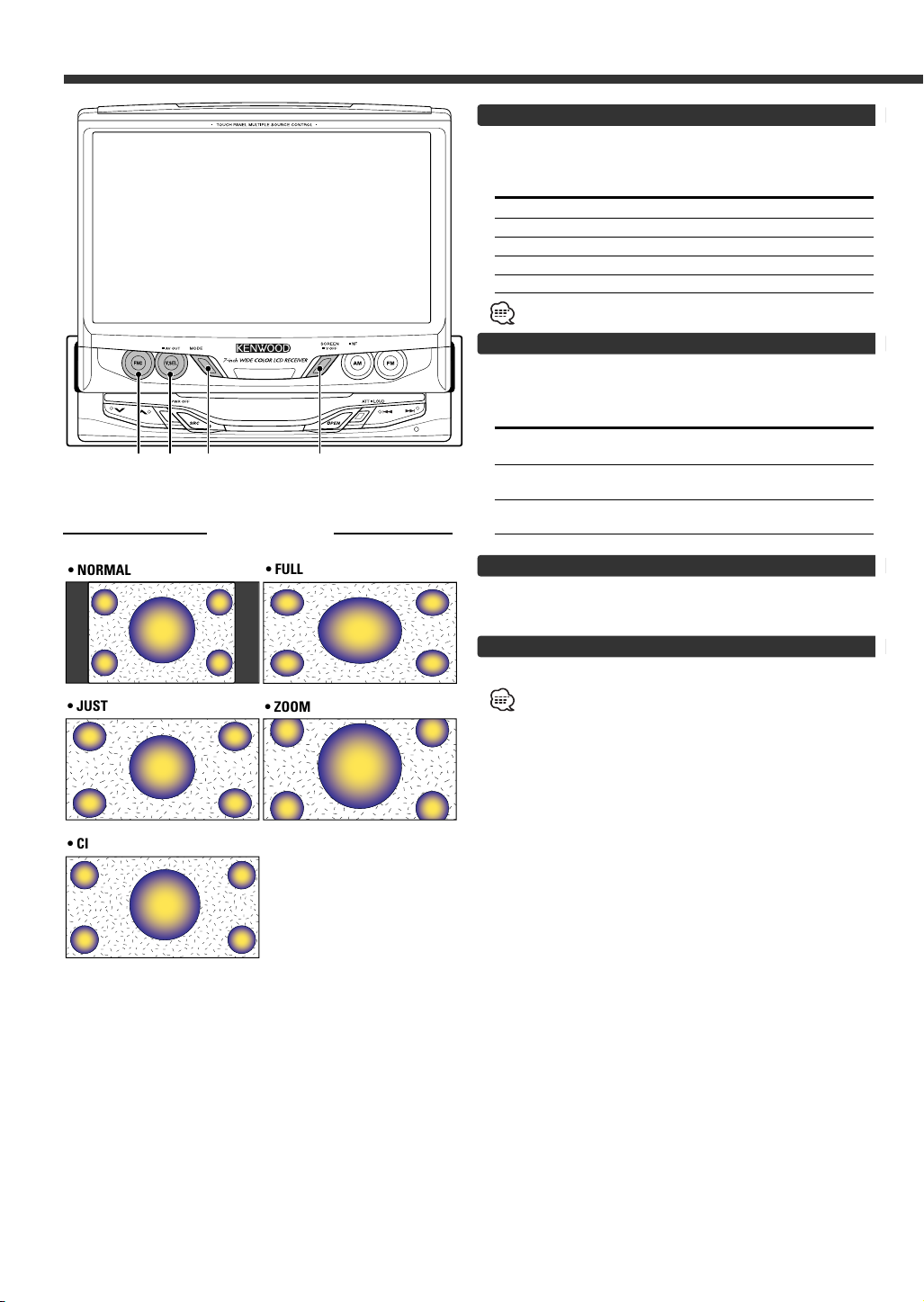
MODEV.SEL SCREENFNC
Screen Mode
• NORMAL
• FULL
Switching the TV/Video Screen Mode
Press the [MODE] button.
Each time the button is pressed the screen mode
switches as follows:
Display Setting
"FULL" Full screen mode
"ZOOM" Zoom screen mode
"JUST" Just screen mode
"CINEMA" Cinema screen mode
"NORMAL" Normal screen mode
You cannot operate when the navigation picture is displayed.
Switching the AV Output
Press the [V.SEL] button for at least 1 second.
Each time the button is pressed for at least 1 second the
AV output switches as follows:
Display Setting
"VIDEO1" Picture/sound input from the AV IN 1
termina
"VIDEO2" Picture/sound input from the AV IN 2
terminal
"TV" Picture/sound of the television
(During the KTC-V500N is connected)
Switching to the Angle/Screen Control Screen
Press the [SCREEN] button.
(☛ Page 7)
• JUST
• CINEMA
• ZOOM
Turning the Monitor Picture Off
Press the [SCREEN] button for at least 1 second.
The picture reappears when the one of the SCREEN, MODE,
V.SEL or FNC buttons is pressed.
6
Page 7
OK
ANGLE CTRL
SCREEN
AUTO
OPEN - CLOSE
ANGLE
SL I DE
ON OFF
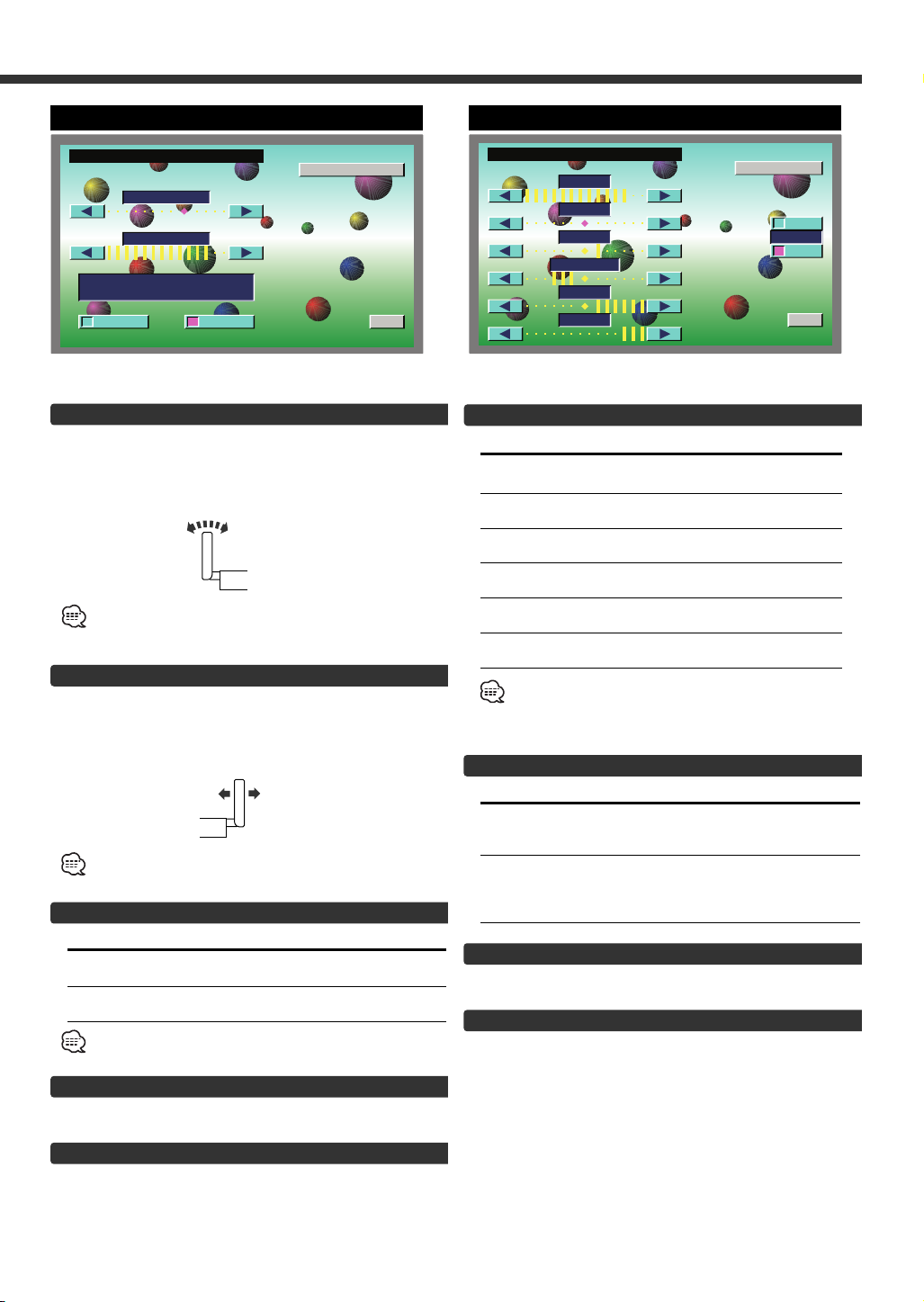
Angle Control Screen
BRT
TIN
COL
OK
SCREEN CTRL
ANGLE
BLK
CONT
DIM
ON
OFF
DIM
Screen Control Screen
Adjusting the Angle Position [ANGLE]
The monitor slants back one step:
Touch the [ 3 ] button.
The monitor slants forward one step:
Touch the [ 2 ] button.
• The angle can be adjusted in 9 steps.
• The next time the monitor is opened it stops at the set
location.
Adjusting the Slide Position [SLIDE]
The monitor to the front:
Touch the [ 3 ] button.
The monitor to the back:
Touch the [ 2 ] button.
The next time the monitor is opened it stops at the set
location.
Automatic Open/Close [AUTO OPEN-CLOSE]
Touch Setting
[7ON] Switch the ACC on/off to open/close the
monitor
[7OFF] Use the OPEN button to open/close
the monitor
If the shift lever or other parts of the vehicle interfere with
the monitor when it opens, select "OFF".
Adjusting the Picture Quality
Item Touch Setting
BRT [ 3 ] Brighter screen
TIN [ 3 ] Stronger green level
COL [ 3 ] Deeper color
CONT [ 3 ] Stronger contrast
BLK [ 3 ] Less black level
DIM [ 3 ] Brighter screen
[ 2 ] Darker screen
[ 2 ] Stronger red level
[ 2 ] Paler color
[ 2 ] Less contrast
[ 2 ] Stronger black level
[ 2 ] Darker screen
• The [ TIN ] and [ COL ] cannot be adjusted for the navigation
picture or the control screen.
• Separate picture quality settings can be stored for the
television, video, control screens and navigation screens.
Auto Dimmer Function On/Off [DIM]
Touch Setting
[7ON] The [DIM] level can be adjusted. Also, when
[7OFF] The [DIM] items can’t be adjusted. Also,
the area around the monitor dark it's at the
brightness level set by the [DIM].
even if the area around the monitor is dark,
it can’t be changed from the brightness set
by [BRT].
Switching to the Angle Control Screen
Touch the [ANGLE] button.
Exit the Screen Control Screen
Touch the [OK] button.
Switching to the Screen Control Screen
Touch the [SCREEN] button.
Exit the Angle Control Screen
Touch the [OK] button.
7
Page 8
Menu Function
12:00MENU
SOUND SETUP
TOUCH
SYSTEMCLOCK
CODE
AV I / F
SOURCE
SYSTEM
TUNER
FMAM
6P1P2P3P4P5P
FM3 P 1 108.5 M
FM- I NFO
Hz
SRC
MENU
FM
FM3 P1 9 2.5 M
FM- I NFO
Hz
TUNER
LOUD
A
TT
AM
6P1P2P3P4P5P
12:00IT
PTY
LIST
INFO
FNC
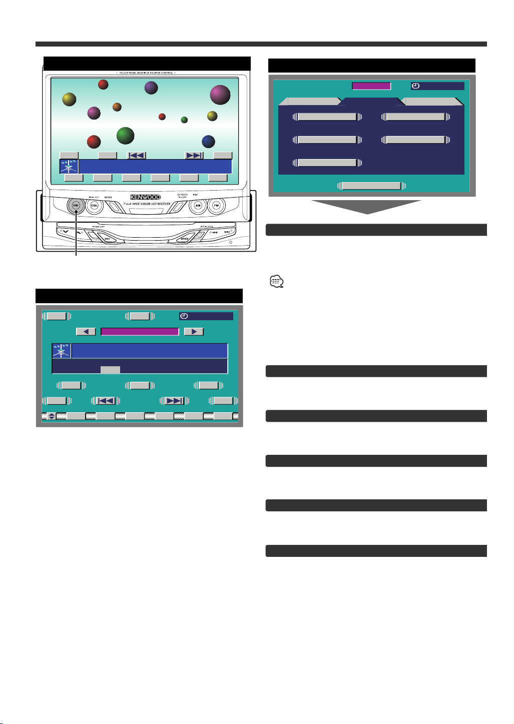
On Screen Control
Control Screen
Menu Screen
Selecting the Menu Screen
1 Displaying the On Screen Control
Press the [FNC] button to display the on screen
control.
If you make no button operation for 10 seconds, the on
screen control is automatically cancelled.
2 Selecting the Control Screen
When the [FNC] button is pressed during on screen
control display, it switches to control screen.
3 Selecting the Menu Screen
Touch the [MENU] button to switch the menu
screen.
8
Selecting the Setup Menu Screen
Touch the [SETUP] button.
(☛ Page 9)
Selecting the Sound Control Menu Screen
Touch the [SOUND] button.
(☛ Page 14)
Selecting the External Display Control Screen
Touch the [EXT] button.
(☛ Page 32) <During the KPA-SD100 is connected>
Selecting the Sensor Box Control Screen
Touch the [SENS] button.
(☛ Page 32) <During the KPA-SS100 is connected>
Exit the Menu Screen
Touch the [SOURCE] button.
Return to source control screen.
Page 9
Setup Function
R
TN
SYNC
1 2:00
R ESET
CLO KCADJUST
CLOCK
ON OFF
12:00MENU
SOUND SETUP
TOUCH
SYSTEMCLOCK
CODE
AV I / F
SOURCE
SYSTEM
TUNER
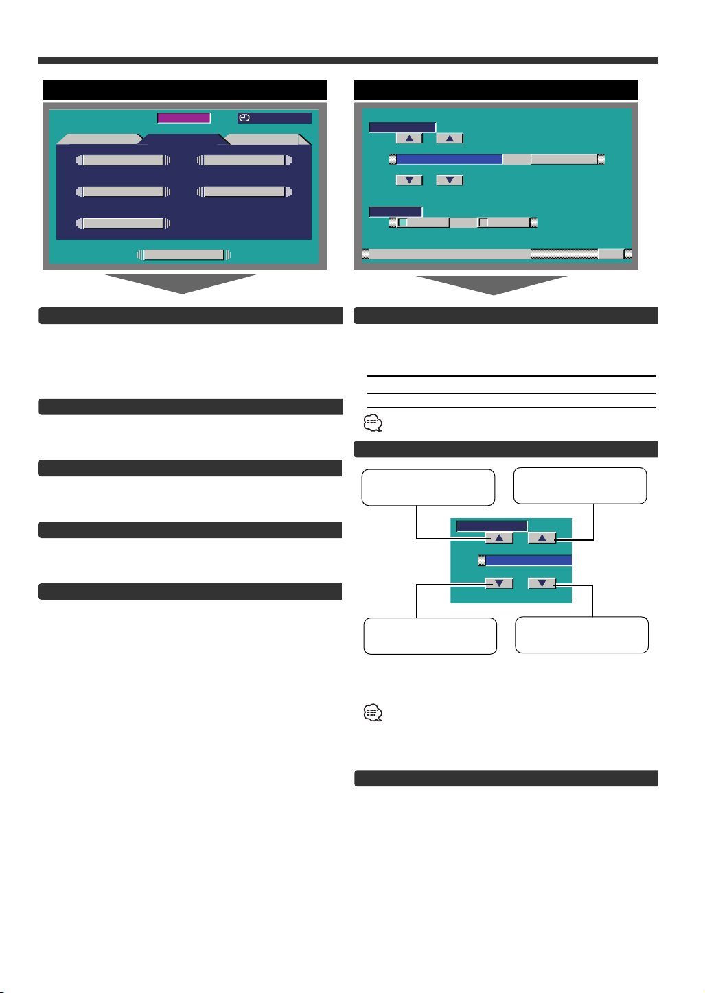
Setup Menu Screen
Selecting the Touch Panel Adjustment Screen
The touch panel can be adjusted if the position
touched and the operation performed do not match.
Touch the [TOUCH] button.
(☛ Page 10)
Selecting the AV Setup Screen
Touch the [AV I/F] button.
(☛ Page 11)
Selecting the Clock Adjustment Screen
Touch the [CLOCK] button.
(☛ Page 9)
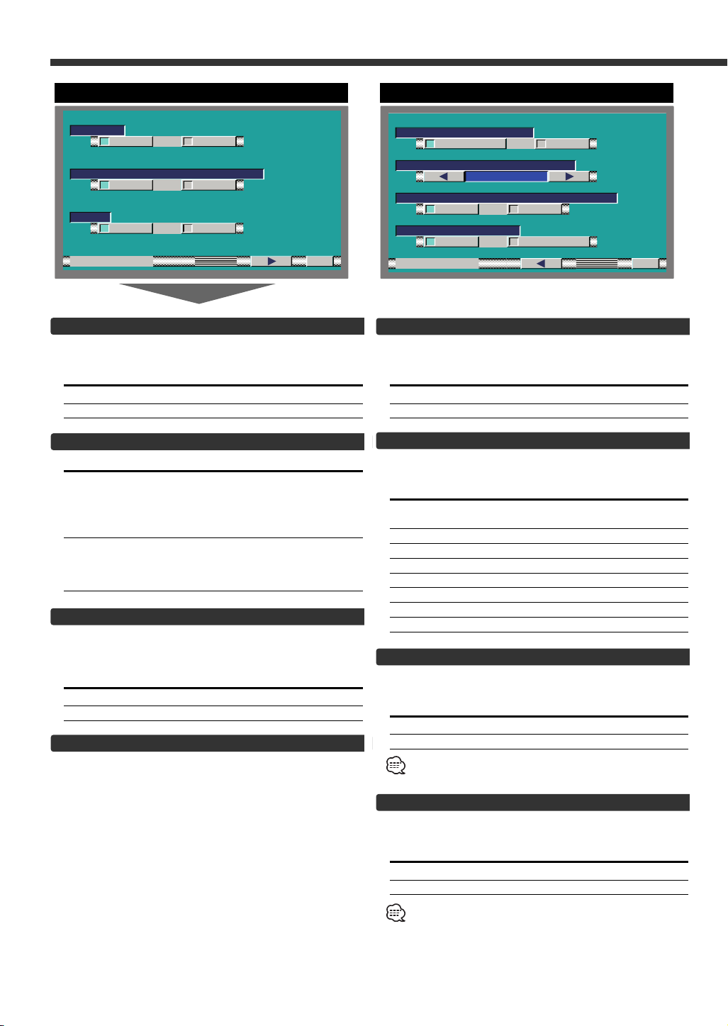
Clock Adjustment Screen
Synchronize Clock [SYNC]
Synchronizing the RDS station time data and this
unit's clock.
Touch Setting
[7ON] Synchronizes the time.
[7OFF] Adjust the time manually.
It takes 3 to 4 minutes to synchronize the clock.
Manual Clock Adjustment [CLOCK]
To advance the hours.
To advance the
minutes.
Selecting the System Setup Screen
Touch the [SYSTEM] button.
(☛ Page 12)
Selecting the Code Security Screen
Press the [CODE] button for at least 2 seconds.
(☛ Page 10)
CLOCK
1 2:00
To make the hours go
back.
Setting the Minutes to "00":
Touch the [RESET] button.
• Touch the [RESET] button while the minute is below "30"
rounds it off, and while the minute is "30" or more rounds it
up.
• This adjustment can be done when the <SYNC> is set as
OFF.
To make the minutes
go back.
Exit the Clock Adjustment Screen
Touch the [RTN] button.
Return to the setup menu screen.
9
Page 10
Setup Function
R
TN
####
1 2 3
4 5 6
7 8 9
0KOCLR
SECUR I TY
1st
R ESETCANCEL
TOUCH PANEL AD JUST
Please Touch
the Ce ter of
the Bu ton in
Right -TopCorner.
n
tthe
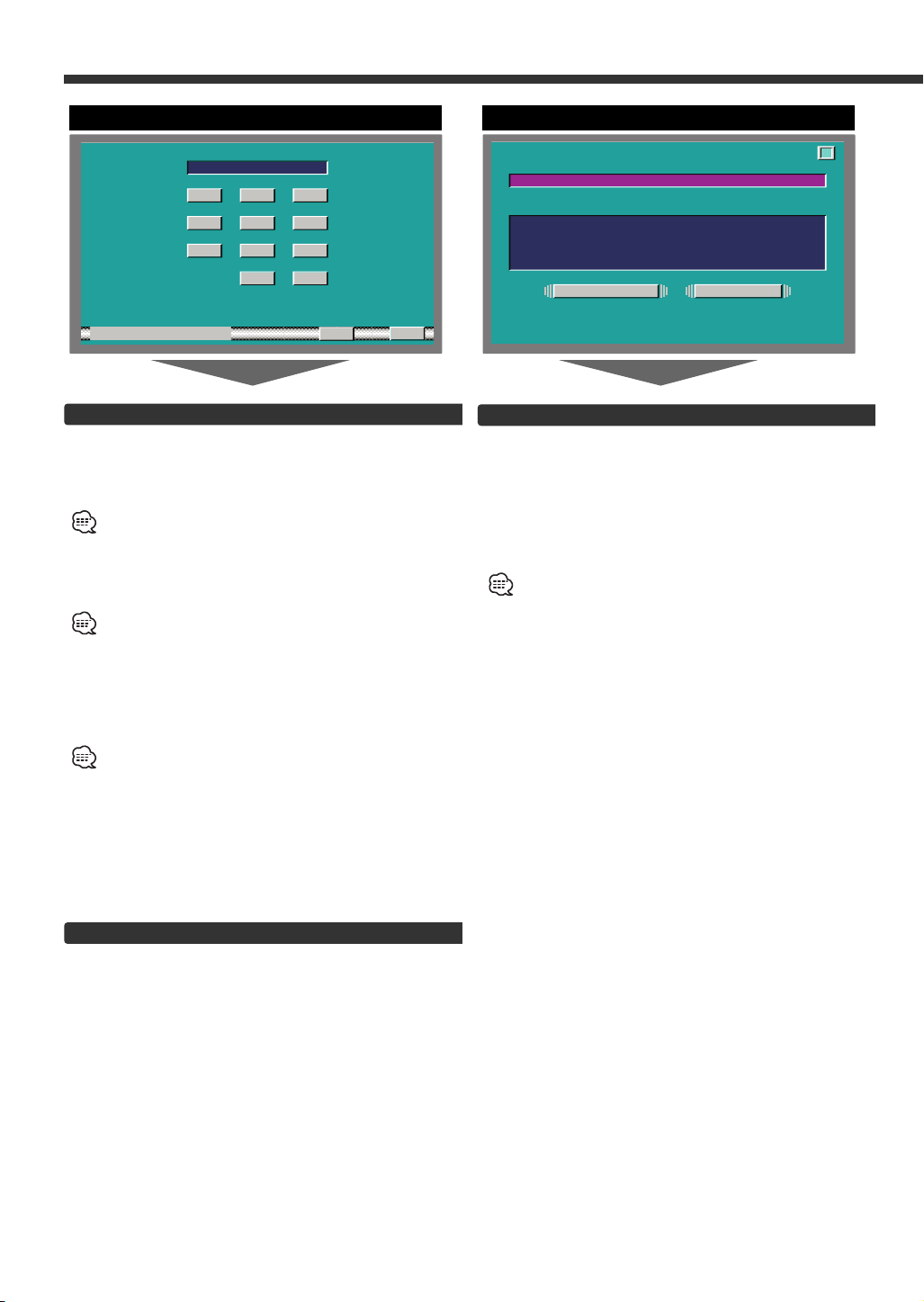
Code Security Screen
Security Code
Because authorization by the Security Code is
required when it's removed from the vehicle,
personalizing this unit is by using the Security Code is
a help in preventing theft.
When the Security Code function is activated, the code can't
be changed and the function can't be released.
Note, the Security Code can be set as the 4 digit number of
your choice.
1 Enter the Security Code
Touch the [0] — [9] button.
If you enter the wrong number, touch [CLR].The last entered
number is cleared.
2 Confirm the Security Code
Touch the [OK] button.
3 Do the step 1 and 2 step operation, and reenter
the security code.
Return to the setup menu screen.
When the wrong Code is entered in steps 1, repeat from
step 1.
Press the Reset button and when it's removed from
the battery power source
1 Turn the power ON.
2 Do the step 1 and 2 operation, and enter the
Security Code.
The “ALL OFF” screen is displayed.
The unit can be used.
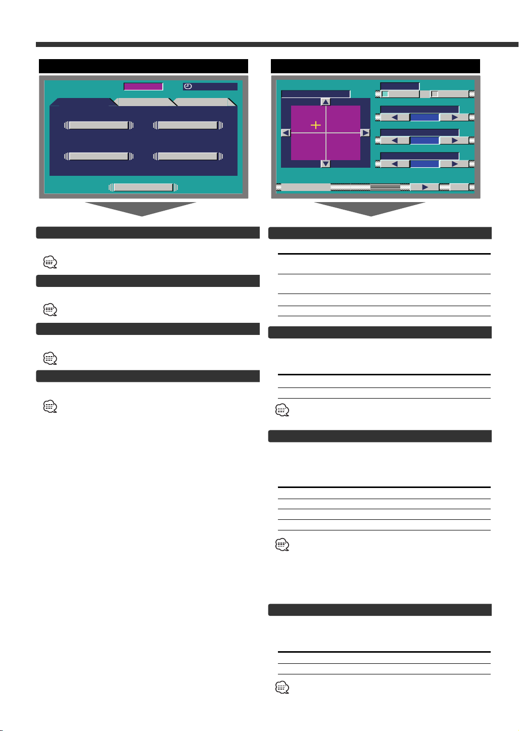
Touch Panel Adjustment Screen
Adjusting the Touch Position
The touch panel can be adjusted if the position
touched and the operation performed do not match.
1 Accurately touch the mark at the upper right.
2 Accurately touch the mark at the lower left.
When the mark at the lower left is touched, the
adjustment is completed and the system setup menu
screen reappears.
• If the [CANCEL] button is touched without touching the
button at the upper right, the adjustment is canceled and the
screen that was set before switching to the system setup
menu reappears.
• If the [CANCEL] button is touched after touching the button
at the upper right, the button at the upper right reappears.
• If the [RESET] button is touched, the settings are reset to the
factory defaults and the setup menu screen reappears.
Exit the Code Security Screen
Touch the [RTN] button.
Return to the setup menu screen.
10
Page 11
NAV
R
TN
AV / FI
RGB I N-
OFF
AV - NI1
AUTO
AV - NI2
TVAV1
AV - UTO
AV2
VD
OFFON
VD
NAV
DV1
DV2
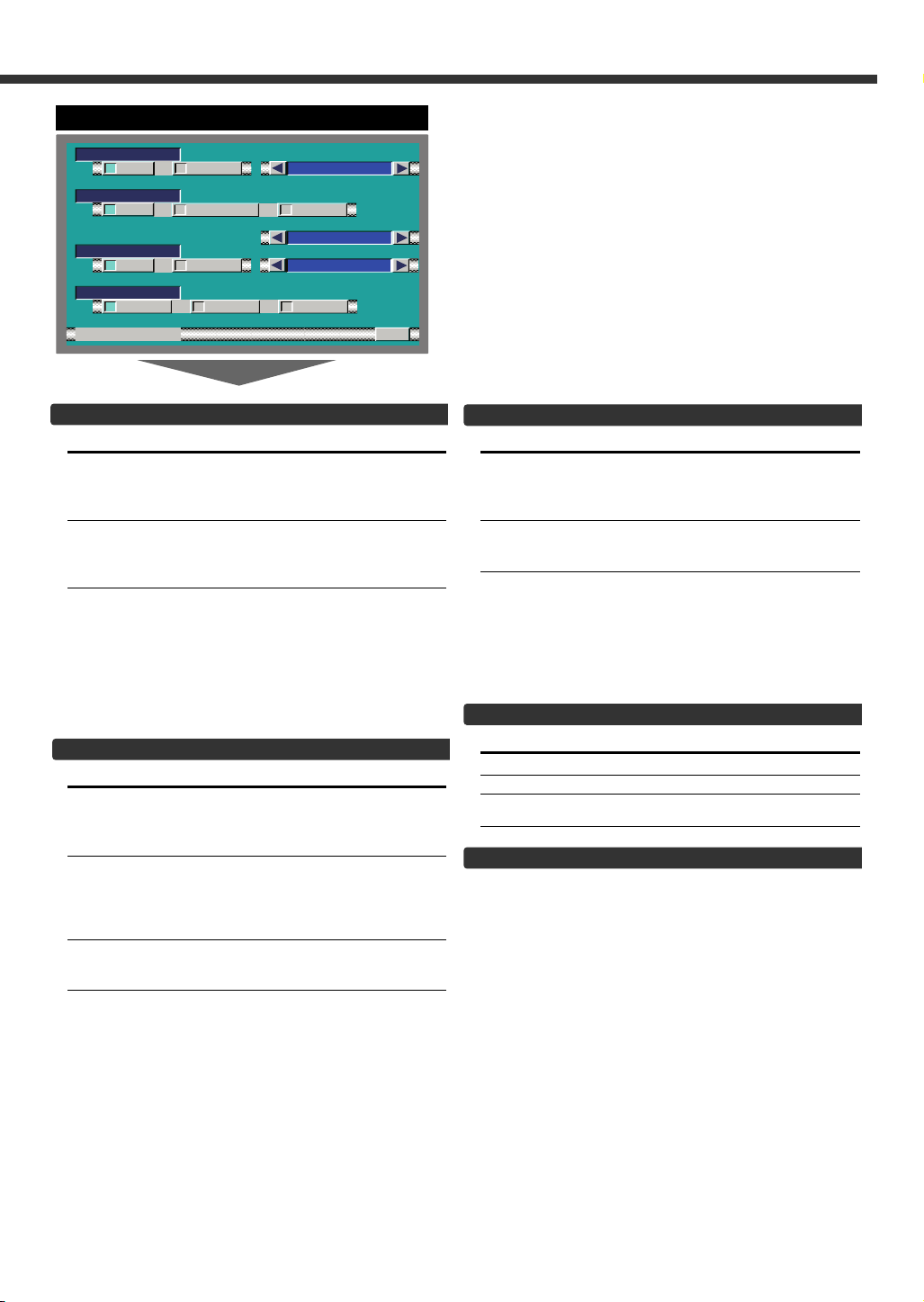
AV Setup Screen
Setting the AV IN-1 Mode [AV-IN1]
Touch Setting
[7NAV] It becomes the navigation mode setting.
[7VD] It becomes the video mode setting.Operate
Select the AV-IN1 input display:
Selecting the display when this device is switched to
internal AV-IN1 terminal input source.
Each time you touch the [ 2 ] or [ 3 ] button, the
display switches as follows:
"VD 1"↔"VIDEO1"↔ "NAV1"↔"DVD1"↔ "VCR1"↔
"VCD1"↔"GAME1"↔"AUX1"
Operate the V.SEL button when the image
from the navigation unit connected to AV
IN1 terminal is shown on the monitor.
the V.SEL button when the image from
the device connected to AV IN1 terminal is
shown on the monitor.
Setting the AV IN-2 Mode [AV-IN2]
Touch Setting
[7VD] It becomes the video mode setting. Operate
[7AUTO] It becomes the auto video mode setting.
[7OFF] It becomes the OFF mode setting.Use this
Select the AV-IN2 input display:
Selecting the display when this device is switched to
internal AV-IN2 terminal input source.
Each time you touch the [ 2 ] or [ 3 ] button, the
display switches as follows:
"VD 2"↔"VIDEO2"↔ "NAV2"↔"DVD2"↔ "VCR2"↔
"VCD2"↔"GAME2"↔"AUX2"↔"CAMERA"
the V.SEL button when the image from the
device connected to AV IN2 terminal is
shown on the monitor.
When the video signal input to the AV IN2
terminal, the monitor image is switched to
the image of the device connected to the AV
IN2 terminal.
setting when there’s nothing connected to
the AV IN2 terminal.
Setting the RGB Mode [ RGB]
Touch Setting
[7ON] It becomes the RGB mode setting. Operate
the V.SEL button when the image from the
the navigation unit connected to I/F terminal
is shown on the monitor.
[7OFF] It becomes the OFF mode setting.Use this
setting when there’s nothing connected to
the I/F terminal.
Select the I/F input display:
Selecting the display when this device is switched to
internal I/F terminal input source.
Each time you touch the [ 2 ] or [ 3 ] button, the
display switches as follows:
"NAV"↔ "DVD"↔"DVB"↔ "RGB"
Setting the AV Output Mode
Touch Setting
[7AV1] Picture/sound from AV IN1 terminal.
[7AV2] Picture/sound from AV IN2 terminal.
[7TV] Picture/sound from television.
(During the KTC-V500N is connected)
Exit the AV Setup Screen
Touch the [RTN] button.
Return to the setup menu screen.
11
Page 12
System Setup Function
R
TN
SYS EMT
OFFON
OFFON
ON SCREENAUTO
BEEP
OFFON
DS I
IND CYEKIATOR
OUSRCE
ON OFF
TIONNAV I NTERRUP
NAV GUIDE
SOUND
GR NEE
ILL IYEKMU
RED
R
TN
SYS EMT
ATT
System Setup Screen-1
Touch Sensor Tone [BEEP]
Setting the operation check sound (beep sound)
ON/OFF.
Touch Setting
[7ON] Touch sensor tone is turned on
[7OFF] Touch sensor tone is turned off
On Screen Display [AUTO ON SCREEN]
Touch Setting
[7AUTO] When a button on the main unit or remote
control unit is pressed, or the disc track is
changed, the audio source control
information is temporarily superimposed on
the picture.
[7MANU] When the lower canter of the screen is
touched while a TV/video picture is displayed,
the audio source control information is
temporarily superimposed on the picture.
Disabled System Indicator [DSI]
A red indicator (Reset button) will blink on the unit
after the ignition Key switch is off , warning potential
thieves.
Touch Setting
[7ON] LED flashes.
[7OFF] LED OFF.
Switching the Setup Screen -1 and 2
Touch the [ 2 ] or [ 3 ] button.
System Setup Screen-2
Selectable Illumination [KEY ILLUMI]
Selecting the button illumination color as green or
red.
Touch Setting
[7GREEN] The illumination color is green.
[7RED] The illumination color is red.
Key Indicator Color [KEY INDICATOR]
Selecting the OPEN and SRC button indicator color.
Touch the [ 2 ] or [ 3 ] button.
Display Setting
"SOURCE" The color changes according to the selected
"MARS" Red
"LIME" Green
"SUNSET Red Green
"SKY" Blue
"VIOLET" Violet
"AQUA" Blue Green
"
MOON
Navigation Announcement [NAV INTERRUPTION]
The navigation voice is output from the front speaker
at navigation voice guide announcement time.
Touch Setting
[7ON] Announcement function is on
[7OFF] Announcement function is off
This function available when the KENWOOD navigation unit is
connected to the I/F terminal.
source.
" White
12
Sound Attenuate [NAV GUIDE]
The rear speaker sound is attenuate during the
navigation voice output time.
Touch Setting
[7ATT] Rear speaker attenuate function is on
[7SOUND] Rear speaker attenuate function is off
This function available when the KENWOOD navigation unit is
connected to the I/F terminal.
Page 13

Exit the System Setup Screen
Touch the [RTN] button.
Return to the setup menu screen.
13
Page 14
Sound Control Function
12:00MENU
SOUND SETUP TUNER
SOURCE
AUD I O
SP SEL
SYS Es
TONE
LR
R
F
AUD I O
BAL / FAD
R
TN
AMP F REQ
MLN
AMP BASS
LOUD
ON OFF
FFO
V.OFFSET
LTF
Sound Control Menu Screen
Selecting the Audio Setting Screen
Touch the [AUDIO] button.(☛ Page 14)
You cannot operate when the standby mode is selected.
Selecting the System Es Setting Screen
Touch the [SYS Es] button.(☛ Page 17)
You cannot operate when the standby mode is selected.
Selecting the Speaker Select Screen
Touch the [SP SEL] button.(☛ Page 16)
You can operate when the standby mode is selected.
Selecting the Tone Control Screen
Touch the [TONE] button.(☛ Page 16)
You cannot operate when the standby mode is selected.
Audio Setting Screen-1
Balance and Fader [BAL/FAD]
Touch Setting
[2]L The sound in the left channel is
emphasized.
[3]R The sound in the right channel is
emphasized.
[5]F The sound in the front channel emphasized.
[∞]R The sound in the rear channel emphasized.
Loudness [LOUD]
Compensating for low and high tones during low
volume.
Touch Setting
[7ON] Loudness function is turned on
[7OFF] Loudness function is turned off
When the Loudness function is ON, the "LOUD" indicator is
ON in the source control screen.
14
B.M.S. (Bass Management System) [AMP BASS]
Adjust the bass boost level of the external amplifier
using the main unit.
Touch the [ 2 ] or [ 3 ] button.
Display Setting
"FLT" Bass boost level is flat.
"+6dB" Bass boost level is low (+6dB).
"+12dB" Bass boost level is mid (+12dB).
"+18dB" Bass boost level is high (+18dB).
• Refer to the catalog or instruction manual for power
amplifiers that can be controlled from this unit.
• For amplifiers there are the model that can be set from Flat
to +18 dB, an the model that can be set from Flat to +12 dB.
When and amplifier is connected that can only be set to
+12dB, even if “+18dB” is selected it won’t operate
correctly.
B.M.S. Frequency Offset [AMP FREQ]
Setting the central frequency boosted by B.M.S.
Touch the [ 2 ] or [ 3 ] button.
Display Setting
"NML" Boost with the normal central frequency.
"LOW" Drop the normal central frequency 20%.
Refer to the catalog or instruction manual for power amplifiers
that can be controlled from this unit.
Page 15
AUD I O
SYSTEM Q
R
TN
ON OFF
OPT40
SYSTEM QEx
ON OFF
2ZONE
Audio Setting Screen-2
Dual Zone System [2 ZONE]
The following operation allows separate sound
sources to control the output of the front and rear
speakers.
Touch Setting
[7ON] The dual zone system function is on.
AV-OUT sound send to the rear speaker.
[7OFF] The dual zone system function is off.
• When the Dual Zone System is ON, there is no rear channel
audio control or other effect.
• When you set the Dual zone system to ON while the nonfading preout is switched ON, the sound of the non-fading
preout isn’t output.
Exit the Audio Setting Screen
Touch the [RTN] button.
Return to the sound control menu screen.
15
Page 16

Sound Control Function
R
TN
WOO E RF
SP SEL
2i type1n A
*
9inch6/6
SPE KEA
R
R
TN
0
TONE
2
1
BAS LS EVEL
MID LEVEL
TRE LEVEL
Speaker Select Screen
Speaker & Woofer Setting
Fine-tuning so that the System Q value is optimal
when setting the speaker and woofer type.
Touch the [2] or [3] button.
In Speaker setting mode [SPEAKER
Display Speaker type
"OFF" Off
"6*9/6inch" For 6 & 6x9 inch speaker
"5/4inch" For 5 & 4 inch speaker
"OEM" For the OEM speaker
In Woofer setting mode [WOOFER]
Display Woofer type
"OFF" Off
"12in typeA" 12 inch A type
"10in typeA" 10 inch A type
"12in typeB" 12 inch B type
"10in typeB" 10 inch B type
"12in typeC" 12 inch C type
"10in typeC" 10 inch C type
"8inch" 8 inch type
"12in typeD" 12 inch D type
"10in TypeD 10 inch D type
Tone Control Screen (Ex:OFF)
Tone Control (System QEx set to OFF)
Touch the [2] or [3] button.
Display Adjustment Item Range
"
BASS LEVEL
"MID LEVEL" Middle level –8 — +8
"TRE LEVEL" Treble level –8 — +8
Exit the Tone Control Screen
Touch the [RTN] button.
Return to the sound control menu screen.
" Bass level –8 — +8
Exit the Speaker Select Screen
Touch the [RTN] button.
Return to the sound control menu screen.
16
Page 17

R
TN
201
1
TONE
1
MID f
MID Q
TRE f
7.15
.020
TRE LEVELMID LEVEL
R
TN
ON OFF
501
BAS fS
1
BAS QS
BASS EXT
TONE
BAS LS EVEL
.020
Tone Control Screen -1 (Ex:ON)
R
TN
00
201
201
HPF R
HPF F
N-F PHASE
80
LPF N-F
SYSTEM Es
N-F LEVEL
NORMAL
R EVERSE
Tone Control Screen -2 (Ex:ON)
Tone Control (System QEx set to ON)
Touch the [2] or [3] button.
Display Adjustment Item Range
"BASS f" Bass Center Frequency 60/70/80/100
"BASS LEVEL"Bass level –8 — +8
"BASS Q" Bass Q Factor 1.00/ 1.25/ 1.50/
"BASS EXT" Bass Extend 7ON
"MID f" Middle Center 0.5/1.0/1.5/
"MID LEVEL" Middle level –8 — +8
"MID Q" Middle Q Factor 1.00/2.00
"TRE f" Treble Center 10.0/12.5/15.0/
"TRE LEVEL" Treble level –8 — +8
• According to the Bass Q Factor setting value, the
frequencies that can be set in Bass Center Frequency
change as shown below.
Bass Q Factor Bass Center Frequency
1.00/1.25/1.50 60/70/80/100 Hz
2.00 60/70/80/150 Hz
• When the Bass Extend is set to ON, low frequency response
is extended by 20%.
Switching the Tone Control Screen -1 and 2
Touch the [ 2 ] or [ 3 ] button.
Exit the Tone Control Screen
Touch the [RTN] button.
Return to the sound control menu screen.
Frequency 2.0kHz
Frequency 17.5 kHz
or 150 Hz
2.00
7OFF
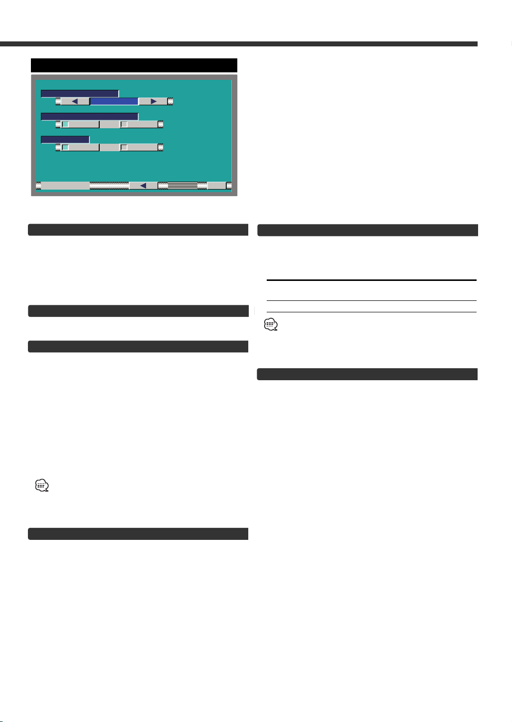
System Es Setting Screen
System Es
Touch the [2] or [3] button.
Display Adjustment Item Range
"HPF F" Front High Pass Filter Through/40/60/
80/100/120/150/
180/220 (Hz)
"HPF R" Rear High Pass Filter Through/40/60/
80/100/120/150/
180/220 (Hz)
"LPF N-F" Non-Fading Low Pass 50/80/120/
Filter Through (Hz)
"N-F LEVEL" Non-Fading level –15 — +15
"N-F PHASE" Non-Fading Phase 7NORMAL (0°)/
7REVERSE(180°)
Exit the System Es Screen
Touch the [RTN] button.
Return to the sound control menu screen.
17
Page 18

Source Control Function (Common operation)
MENU
FM
FM3 P1 9 2.5 M
FM- I NFO
Hz
TUNER
LOUD
A
TT
AM
6P1P2P3P4P5P
12:00IT
PTY
LIST
INFO
FMAM
6P1P2P3P4P5P
FM3 P1 108.5 M
FM- I NFO
Hz
SRC
On Screen Control
Displaying the On Screen Control
Selecting the On Screen Control
Press the [FNC] button to switch the on screen control
display.
If you make no button operation for 10 seconds, the on
screen control is automatically cancelled.
Selecting the Control Screen
When the FNC button is pressed during on screen
control display, it switches to control screen.
Changing the Audio Source Mode
<In Monitor’s button/ On Screen Control>
Press/ Touch the [SRC] button.
<In Source Control Screen>
Touch the [2] or [3] button.
Source required Display
FM/AM Tuner "TUNER"
External CD player "CD"
External disc changer "DISC-CH"
Video & External TV Tuner "AV"
Auxiliary input "AUX"
External SIRIUS Tuner "SIRIUS"
External Weather Band Tuner "WBT"
Standby (Illumination only mode) "ALL OFF"
For Auxiliary input one of the below optional accessories is
necessary.
- KCA-S210A
- CA-C1AX
- CD changer with an Auxiliary input function installed.
Volume
Increasing Volume:
Press the [u] button.
Decreasing Volume:
Press the [d] button.
18
Source Control Screen
Attenuator
Turning the volume down quickly.
ATT FMAMFNC SRC MODE
4 ¢
"MD-CH"
Press the [ATT] button.
Each time the button is pressed the Attenuator turns ON
or OFF.
When it’s ON, the "ATT" indicator is ON.
Loudness
Compensating for low and high tones during low
volume.
Press the [ATT] button for at least 1 second.
Each time the button is pressed for at least 1 second the
Loudness turns ON or OFF.
When it’s ON, "LOUD" indicator is ON.
Non-fading Output
Turning the Non-fading output ON or OFF.
Press the [AM] button for at least 1 second.
Each time the button is pressed for at least 1 second the
Non-fading output switches ON or OFF.
Switching to the Menu Screen
Touch the [MENU] button.(☛ Page 8)
Changing the Function Buttons
Touch the [ ] button.
Each time the button is touched the under function
buttons change.
Changing the Background Mode for the Control
Screen
You can select the background between 11 different
patterns for the source control screen and menu
screen.
Press the [MODE] button.
Each time the button to change the background mode.
Page 19

TEL Mute
The audio system automatically mutes when a call
comes in.
When a call comes in
"CALL" is displayed.
The audio system pauses.
Listening to the audio during a call
Press the [SRC] button.
The "CALL" display disappears and the audio system
comes back ON.
When the call ends
Hang up the phone.
The "CALL" display disappears and the audio system
comes back ON.
19
Page 20

FM/AM Tuner Control Function
FMAM
6P1P2P3P4P5P
FM3 P1 108.5 M
FM- I NFO
Hz
SRC
MENU
FM
FM3 P1 9 2.5 M
FM- I NFO
Hz
TUNER
TIMANU
ST
AM
6P1P2P3P4P5P
12:00IT
CRSC
RDS
PTY
LIST
INFO
On Screen Control
4 ¢
Selecting the FM Band
Press/ touch the [FM] button.
Each time the button is pressed/ touched it switches
between the FM1, FM2, and FM3 bands.
Selecting the AM Band
Press/ touch the [AM] button.
Tuning
Press/ touch the [4] or [¢] button.
During reception of stereo stations the "ST" indicator
is ON
Station Preset Memory
Putting the station in the memory.
1 Select the band
Press/ touch the [FM] or [AM] button.
2 Select the frequency to put in the memory
Press/ touch the [4] or [¢] button.
3 Put the frequency in the memory
Touch the [P1] — [P6] button for at least 2 seconds.
On each band, 1 station can be put in the memory on
each [P1] — [P6] button.
Control Screen -1
Auto Memory Entry
Putting stations with good reception in the memory
automatically.
FMAM
1 Select the band for Auto Memory Entry
Touch the [FM] or [AM] button.
2 Open Auto Memory Entry
Touch the [AME] button for at least 2 seconds.
When 6 stations that can be received are put in the
memory Auto Memory Entry closes.
Seek Mode
Sets the seeking mode.
Touch the [SEEK] button.
Each time the button is touched the seeking mode
switches as shown below.
Seek mode(display) Operation
Auto seek ("AUTO1") Automatic search for
Preset station seek ("AUTO2") Search in order of the
stations in the Preset memory.
Manual ("MANU") Normal manual tuning
CRSC (Clean Reception System Circuit)
Temporarily have reception switched from stereo to
mono to reduce multi-path noise when listening to the
FM station.
Touch the [CRSC] button.
Each time the button is pressed CRSC turns ON or OFF.
When it's ON, the CRSC indicator is ON.
a station.
control.
Preset Tuning
Calling up the stations in the memory.
1 Select the band
Press/ touch [FM] or [AM] button.
2 Call up the station
Touch the [P1] — [P6] button.
20
Page 21

MENU
FM
TUNER
TIMANU
ST
AM
12:00IT
CRSC
AME
SEEK
CRSCNAME
RDS
FM3 P1 108.5 M
FM- I NFO
Hz
PTY
DISP
LIST
INFO
Control Screen -2
R
TN
INFO
RAD I O - TEXT
################
###
################
###
################
###
################
###
################
###
################
###
################
###
################
###
################
###
################
###
################
###
Traffic Information
Switching to traffic information automatically when a
traffic bulletin starts even when you aren't listening to
the radio.
Touch the [TI] button.
Each time the button is touched the Traffic Information
function turns ON or OFF.
When it's ON, "TI" indicator is ON.
When a traffic bulletin starts, "TRAFFIC INFO" is
displayed it and it switches to traffic information.
During reception of a AM station when the Traffic
Information function is turned ON, it switches to a FM
station.
Switching Display
Switching the information displayed.
Touch the [DISP] button.
Each time the button is touched the display switches as
shown below.
Information Display
SNPS or Program Service name "STATION NAME"
Radio text "RADIO-TEXT"
Switching to the Radio Text Information Screen
The whole sentence of radio text is displayed.
Touch the [INFO] button.
Switching to the FM/AM List Screen
Touch the [LIST] button. (☛ page 22)
Switching to the PTY Search Screen
Touch the [PTY] button. (☛ page 22)
This function can't be used during a traffic bulletin or AM
reception.
Switching to the Name Set Screen
Touch the [NAME] button.
For the setting method refer to the name set screen
(☛ page 28).
You cannot operate unless the parking brake is set.
Page Up/Down for the Radio text
Touch the [5] or [∞] button.
When all text are displayed on the information screen, [∞]
and [5] do not appear.
Exit the Information Screen
Touch the [RTN] button.
Return to the source control screen.
21
Page 22

FM/AM Tuner Control Function
1
2
3
4
5
6R
TN
SNPS########
SNPS########
SNPS########
SNPS########
SNPS########
SNPS########
AM
FM
DISP
FM1 P1 9 2.5 M
Hz
FM- J J
T op40
R
TN
SEARCH
PTY
sweN
SET
sweN
PUSER TY
FM/AM List Screen
FM/AM List Screen
Selecting the FM band
Touch the [FM] button.
Each time the button is touched it switches between the
FM1, FM2, and FM3 bands.
Selecting the AM band
Touch the [AM] button.
Switching the SNPS and PS Name
Touch the [DISP] button.
Call up the station
Touch the list.
Exit the FM/AM List Screen
Touch the [RTN] button.
Return to the source control screen.
PTY Search Screen
Selecting the Program Type and searching for a
station.
Select the Program Type
Touch the [2] or [3] button.
Each time the button is touched the Program Type
switches as shown below.
No. Program Type Display
1. Speech "All Speech"
2. Music "All Music"
3. News "News"
4. Information "Information"
5. Sports "Sports"
6. Talk "Talk"
7. Rock "Rock"
8. Classic Rock "Classic Rock"
9. Adult Hits "Adult Hits"
10. Soft Rock "Soft Rock"
11. Top 40 "Top 40"
12. Country "Country"
13. Oldies "Oldies"
14. Soft "Soft"
15. Nostalgia "Nostalgia"
16. Jazz "Jazz"
17. Classical "Classical"
18. R & B "Rhythm & Blues"
19. Soft R & B "Soft R & B"
20. Language "Foreign Language"
21. Religious Music "Religious Music"
22
Search for the selected Program Type station
Registration of a station as a PTY
Registering a Program Type for stations with no PTY
data.
Exit the PTY Search Screen
PTY Search Screen
22. Religious Talk "Religious Talk"
23. Personality "Personality"
24. Public "Public"
25. College "College"
26. Weather "Weather"
Speech and Music include the Program type below.
Speech: No.3
Music: No.7
Touch the [SEARCH] button.
When you want to search for other stations touch the
[SEARCH] button again.
When the selected Program Type isn't found, "NO PTY" is
displayed. Select another Program Type.
Touch the [SET] button for at least 2 seconds.
Touch the [RTN] button.
Return to the source control screen.
— 6, 20, 22
— 19, 21
— 26
Page 23

AV Control Function (TV Control: During the KTC-V500N is connected)
MENU
TV
TV1 P1 12 c h
NO NAME
AV
MANU
AV
6P5P4P3P2P1P
12:00IT
WIDE AV OUT
1 0 c hT V
1
A U T O 2
C I N E MA O 1
V I D E
TV
6P1P2P3P4P5P
SRC
TV1 A1 P1 12ch
NO N AME
MENU
TV
TV1 P1 12 c h
NO NAME
AV
MANU
AV
12:00IT
AME
8P7P
SEEK
LIST
NAME
On Screen Control
Selecting the On Screen Control
Touch the centre part.
If you make no button operation for 10 seconds, the on
screen control is automatically cancelled.
4 ¢
Control Screen-1
Control Screen-2
FMAM
Selecting the Preset Band
<In Monitor’s button>
Press the [FM] button.
Each time the button is pressed the preset band
switches between the TV1 and TV2.
<In Screen’s button>
Touch the [TV] button.
Each time the button is touched the preset band
switches between the TV1 and TV2.
Selecting the Video Input
<In Monitor’s button>
Press the [AM] button.
Each time the button is pressed the video input switches
between the AV IN 1, AV IN2 and RGB.
<In Screen’s button>
Touch the [AV] button.
Each time the button is touched the video input switches
between the AV IN 1, AV IN2 and RGB.
Video1 and 2: During “AV IN1“ and “AV IN2“ set to “VD”,
Seek Mode
Sets the seeking mode.
Touch the [SEEK] button.
Each time the button is touched the seeking mode
switches as shown below.
Seeking mode(display) Operation
Auto seek ("AUTO1") Automatic search for
Preset station seek ("AUTO2") Search in order of the
stations in the Preset memory.
Manual ("MANU") Normal manual
a station.
seeking control.
Selecting the Channel
<In Monitor’s button>
Press the [4] or [¢] button.
<In Screen’s button>
Touch the [4] or [¢] button.
<On TV Picture>
Touch the left or right side part.Preset
Station Preset Memory
Putting the station in the memory.
1 Select the band
Press/ touch the [FM] button.
2 Select the channel to put in the memory
Press/ touch the [4] or [¢] button.
3 Put the channel in the memory
Touch the [P1] — [P8] button for at least 2 seconds.
On each band, 1 station can be put in the memory on
each [P1] — [P8] button.
23
Page 24

AV Control Function
MENU
TV
TV1 P1 12 c h
NO NAME
AV
MANU
AV
12:00IT
AME
8P7P
SEEK
LIST
NAME
TV1 P1 12ch
1
2
3
4
5
6R
TN
INFO-TV
TV- JAPAN
3ch
10ch
11ch
12ch
TV
MENU
TV
TV1 P1 12 c h
NO NAME
AV
MANU
AV
6P5P4P3P2P1P
12:00IT
Control Screen-1
Control Screen-2
Auto Memory Entry
Putting stations with good reception in the memory
automatically.
1 Select the band for Auto Memory Entry
Touch the [TV] button.
2 Open Auto Memory Entry
Touch the [AME] button for at least 2 seconds.
When 8 stations that can be received are put in the
memory Auto Memory Entry closes.
TV List Screen
TV List Screen
Selecting the TV preset band
Touch the [TV] button.
Each time the button is touched it switches between the
TV1, and TV2 bands.
Switching the List
Touch the [ ] button.
Each time the button is touched the list switches
between the [P1] — [P6] and [P7] — [P8].
Call up the Channel
Touch the list.
Exit the TV List Screen
Touch the [RTN] button.
Return to the source control screen.
Recalling a Preset Station
1 Select the band
2 Call up the station
Touch the [P1] — [P8] button.
Switching to the TV List Screen
Touch the [LIST] button.
Switching to the Name Set Screen
Touch the [NAME].
For the setting method refer to the name set screen
(☛ page 28).
You cannot operate unless the parking brake is set.TV List
24
Page 25

CD Player Control Function
SRC
REP
SCN
RDM
T
r
ac
k
12 12:3
DNPS###########
4
#
REPSCN RDM
MENU
T
r
ac
k
12 12:3
DNPS###########
4
#
CD
REP
12:00IT
MENU
T
r
ac
k
12 12:3
DNPS###########
4
#
CD
REP
12:00IT
NAME
On Screen Control
4 ¢
Pause and play
Touch the [38] button.
Each time the button is touched it pauses and plays.
Fast Forwarding and Reversing
Fast Forwarding
Hold down on the [¢] button.
Release your finger to play the disc at that point.
Reversing
Hold down on the [4] button.
Release your finger to play the disc at that point.
Track Search
Selecting the song you want to hear.
Press/ touch the [4] or [¢] button.
Track Repeat
Replaying the song you're listening to.
Touch the [REP] button.
Each time the button is touched the Track Repeat turns
ON or OFF.
When it's ON, "REP" indicator is ON.
Control Screen-1
Control Screen-2
Random Play
Playing all the songs on the disc in random order.
Touch the [RDM] button.
Each time the button is touched Random Play turns ON
or OFF.
When it's ON, the "RDM" indicator is ON.
When the [¢] button is touched, the next song select
starts.
Switching to the Name Set Screen
Touch the [NAME] button.
For the setting method refer to the name set screen
(☛ page 28).
You cannot operate unless the parking brake is set.
Track Scan
Playing the first part of each song on the disc you are
listening to and searching for the song you want to
listen to.
1 Start Track Scan
Touch the [SCN] button.
"SCN" indicator is ON.
2 Release it when the song you want to listen to is
played
Touch the [SCN] or [38] button.
25
Page 26

Disc Changer Control Function
DREP
REPSCN
MRDM
RD
M
MENU
D+
Disc
5-T
rack
12 2:34
DISCTEXT####
DISC-C
REP
D-
12:00
H
IT
D+D–
SRC
Disc
5-T
rack
12 2:34
DISCTEXT####
DREP
REP
SCN
MRDM
RDM
Pause and play
Touch the [38] button.
Each time the button is touched it pauses and plays.
Fast Forwarding and Reversing
Fast Forwarding:
Hold down on the [¢] button.
Release your finger to play the disc at that point.
Reversing:
Hold down on the [4] button.
Release your finger to play the disc at that point.
Track Search
Selecting the song you want to hear.
Press/ touch the [4] or [¢] button.
Album Search
Selecting the disc you want to hear.
Touch the [D+] or [D–] button.
Press the [FM] or [AM] button.
The 3+1MD changer cannot be operated when 4 discs are
inserted.
Track Repeat
Replaying the song you're listening to.
Touch the [REP] button.
Each time the button is touched the Track Repeat turns
ON or OFF.
When it's ON, "REP" indicator is ON.
26
On Screen Control
4 ¢
m Repeat
Control Screen-1
Album Repeat
Replaying the disc in the Disc changer you're listening
FMAM
to.
Touch the [DREP] button.
Each time the button is pressed Album Repeat turns ON
or OFF.
When it's ON, the "DREP" indicator is ON.
The 3+1MD changer cannot be operated when 4 discs are
inserted.
Track Scan
Playing the first part of each song on the disc you are
listening to and searching for the song you want to
listen to.
1 Start Track Scan
Touch the [SCN] button.
"SCN" indicator is ON.
2 Release it when the song you want to listen to is
played
Touch the [SCN] or [38] button.
Random Play
Playing all the songs on the disc in random order.
Touch the [RDM] button.
Each time the button is touched Random Play turns ON
or OFF.
When it's ON, the "RDM" indicator is ON.
When the [¢] button is touched, the next song select
starts.
Magazine Random Play
Play the songs on all the discs in the disc changer in
random order.
Touch the [MRDM] button.
Each time the button is touched Magazine Random Play
turns ON or OFF.
When it's ON, the "MRDM" indicator is ON.
• When the [¢] button is touched, the next song select
starts.
• The 3+1MD changer cannot be operated when 4 discs
are inserted.
Page 27

MENU
D+
Disc
5-T
rack
12 2:34
DISCTEXT####
DISC-C
REP
D-
12:00
H1
IT
DISPINFO
LIST
NAME
Control Screen-2
R
TN
INFO
D-TEXT
################
###
################
###
################
###
################
###
################
###
################
###
################
###
################
###
################
###
################
###
################
###
1
2
3
4
5
6R
TN
DISP
Bes t Hi t - V1
Disc
5-T
rack
12 12:34
Bes t Hi t - V2
NO TEX T
NO TEX T
NO TEX T
NO TEX T
TTD- EX LIST
1
2
3
4
R
TN
Bes t Hi t - V1
Disc
3-T
rack
12 12:34
Bes t Hi t - V2
NO TITLE
Switching Display
Touch the [DISP] button.
Each time the button is touched the display switches as
shown below.
Display Information
"DNPS" Disc name (CD only)
"D-TEXT"/"D-TITLE" Disc text/ Disc title
"T-TEXT"/"T-TITLE" Track text/ Track title
Switching to the Text/Title Information Screen
The whole sentence of CD text or MD title is
displayed.
Touch the [INFO] button.
Disc List Screen <CD changer>
Disc List Screen <MD changer>
Page Up/Down for the CD text or MD title
Touch the [5] or [∞] button.
When all text are displayed on the information screen, [∞]
and [5] do not appear.
Exit the Information Screen
Touch the [RTN] button.
Return to the source control screen.
Switching to the Disc List Screen
Touch the [LIST] button.
Switching to the Name Set Screen
Touch the [NAME] button.
For the setting method refer to the name set screen
(☛ page 28).
You cannot operate unless the parking brake is set.
Disc List Screen
Changing the Disc List (10 disc changer only)
Touch the [ ] button.
Each time the button is touched †he disc list switches
between the disc1-6 and disc 7-10.
Switching the Display for Discs (CD only)
Touch the [DISP] button.
Each time the button is touched the list switches
between the DNPS and CD text.
Selecting the Disc
Touch the list.
The 3+1MD changer cannot be operated when 4 disks are
inserted.
Exit the Disc List Screen
Touch [RTN] button.
Return to the source control screen.
27
Page 28

Name Set Function
A
NAME#PRESET#
B C D E F
G H I J K L
M N O P Q R
S T U V W X
Y Z , . • -
OK
NAME SET
SPC
AB
ab
12
Ää
Name Set Screen
Station Name Preset (SNPS)/ Disc Name Preset
(DNPS)
1 Move the cursor to the enter character position
Touch the [<] or [>] button.
2 Select the character type
Touch the [AB], [ab], [12] or [Ää] button.
3 Select the character list
Touch the [∞] or [5] button.
When all characters are displayed on the character list, [∞]
and [5] do not appear.
4 Touch a character.
5 Repeat steps 1 through 4 and enter the name.
• You can enter up to 12 characters for each name.
• To enter a space, touch the [SPC] button.
6 Exit name set screen
Touch the [OK] button.
• Media that you can attach names to
– FM/AM tuner: 30 FM/AM stations in all.
– TV tuner: 100 stations.
– External CD changer/ player: Varies according to the
CD changer/player. Refer to the CD changer/ player
manual.
• The name of a CD can be changed by the same operation
you used to name it.
28
Page 29

Other Option Control Function
WB T - 01 1 6 2.475M
Hz
SRC
MENU
WB T - 0 1 162 . 475M
Hz
WB T
12:00IT
7 Weather Band Tuner Control
On Screen Control
Selecting the Channels
<In Monitor’s button>
Press the [4] or [¢] button.
<In Screen’s button>
Touch the [4] or [¢] button.
Control Screen
4 ¢
29
Page 30

Other Option Control Function
MENU
BAND
SEEK1
6P5P4P3P2P1P
12:00
SIRIUS
SP1 21c
CHANNE L # NAME###h#
IR1
SCN
SRCH
INFO
SIR1 P1 321c
###############
h
#
SRC
BAND
6P1P2P3P4P5P
C H#NAME#########
################
R
TN
CATEGORY#NAME###
CATEGORY#NAME###
CATEGORY#NAME# # #
CATEGORY#NAME# # #
CATEGORY#NAME###
7 SIRIUS Tuner Control
On Screen Control
Selecting the Preset Band
<In Monitor’s button>
Press the [FM] button.
Each time the button is pressed the preset band
switches between the SIR1, SIR2, SIR3 and SIR4.
<In Screen’s button>
Touch the [BAND] button.
Each time the button is touched the preset band
switches between the the SIR1, SIR2, SIR3 and SIR4 .
Selecting the Channel
<In Monitor’s button>
Press the [4] or [¢] button.
<In Screen’s button>
Touch the [4] or [¢] button.
Station Preset Memory
Putting the channel in the memory.
1 Select the band
Press/ touch the [FM] or [BAND] button.
2 Select the channel to put in the memory
Press/ touch the [4] or [¢] button.
3 Put the channel in the memory
Touch the [P1] — [P6] button for at least 2 seconds.
On each band, 1 station can be put in the memory on
each [P1] — [P6] button.
Only the channel number is stored. Category information is
not stored.
30
4 ¢
Control Screen-1
Seek Mode
Sets the seeking mode.
Touch the [SEEK] button.
Each time the button is touched the Seek mode
switches as shown below.
FM
Ddisplay Operation
"SEEK1" Normal manual seeking control.
"SEEK2" Search in order of the channels in
the Preset memory.
Channel Scan
Scanning for the channel you want to listen to.
1 Start Channel Scan
Touch the [SCN] button.
"SCN" indicator is ON.
2 Release it when the channel you want to listen to
is selected
Touch the [SCN] button.
Channel Search
Searching the program category and Channel.
1 Switching to the category select screen
Touch the [SRCH] button
The category select screen is displayed.
Canceling the category select screen
Touch [RTN] button.
Return to the source control screen.
Page 31

MENU
BAND
SEEK1
12:00
SIRIUS
SP1 21c
CHANNE L # NAME###h#
IR1
SRCH
SCN
SEEK
SCN
INFO
Control Screen-2
C H#NAME#########
################
CHANNEL#NAME####
CHANNEL#NAME####
CHANNEL#NAME####
CHANNEL#NAME####
CHANNEL#NAME####
R
TN
INFO
123ch
CHANNEL#NAME####
###
CATEGORY#NAME# # #
###
ARTIST#NAME#####
###
ESN:123456789012
###
################
###
################
###
################
###
################
###
S ONG# TITLE######
###
ARTIST#NAME#####
###
ALBUM#TITLE#####
###
2 Page Up/Down for the Category
Touch the [5] or [∞] button.
3 Select the Category
Touch the list.
The channel select screen is displayed.
4 Page Up/Down for the Channel
Touch the [5] or [∞] button.
5 Select the Channel
Touch the list.
Switching to the Information Screen
The whole sentence of SIRIUS information is
displayed.
Touch the [INFO] button.
Page Up/Down for the text
Touch the [5] or [∞] button.
When all text are displayed on the information screen, [∞]
and [5] do not appear.
Exit the Information Screen
Touch [RTN] button.
Return to the source control screen.
Program Descriptive Text
Program Descriptive Text data is song (or program) specific
textual information that is transmitted to the receiver and
displayed on Information screen.
Generally, most stations will contain the artist name and
song title information. Additional information such as album
and record label may also be provided.
[ESN] (Electronic Serial Number)
It is especially important to retain the unit serial number and
the electronic Sirius Identification number for service
activation and potential future service changes.
31
Page 32

Other Option Control Function
12:00
EXT .D I SPLAY
R
TN
12:00
SENSOR
R
TN
NORTH . D IR.8
ADJ UST
7 External Display Control 7 Sensor Box Control
External Display Control Screen
<Refer to the KPA-SD100 instruction manual for
details on external box functions>
Switching the Display
Touch the [2] or [3] button.
Exit the External Display Control Screen
Touch the [RTN] button.
Return to the menu screen.
Sensor Box Control Screen
<Refer to the KPA-SS100 instruction manual for
details on sensor box functions>
Setting the Menu
1 Touch the [ADJUST] button.
Select the item
Touch the [2] or [3] button.
Set the function
Touch the [5] or [∞] button.
2 Touch the [ADJUST] button.
Exit the Sensor Box Control Screen
Touch the [RTN] button.
Return to the menu screen.
32
Page 33

33
Page 34

Remote Control Function
SRC
SRC
4
TRACK
¢
TUNE
4
¢
38
FM+
AM–
38
FM
DISC
AM
+
ATT
V.SEL
ATT
V.SEL AV OUT
ABC DEF
123
GHI JKL MNO
456
PRS TUVQZWXY
799
0
DIRECT
OK
–
DIRECT/OK
AV OUT
1 – 0
A – Z
Monitor Control Function
3 Switching the Monitor’s Picture
Press the [V.SEL] button.
Each time the button is pressed the monitor’s picture
switches.
3 Switching the AV Output Mode
Press the [AV OUT] button.
Each time the button is pressed the AV out mode
switches.
Source Control Function (Common operation)
3 Select the Audio Source Mode
Press the [SRC] button.
Each time the button is pressed the audio source
switches.
3 Volume
Increasing Volume
Press the [+] button.
Decreasing Volume
Press the [–] button.
3 Attenuator
Press the [ATT] button.
Each time the button is pressed the Attenuator turns
ON or OFF.
Loading and Replacing the Batteries for the
Remote
2 CAUTION
Do not set the remote on hot places such as above
the dashboard.
1. Use two "AAA" batteries.
Slide the cover while pressing downwards to
remove it as illustrated.
2. Insert the batteries with the ª and · poles
aligned properly following the illustration inside
the case.
2 WARNING
Store unused batteries out of the reach of children.
Contact a doctor immediately if the battery is
accidentally swallowed.
• The provided batteries are intended for use in
operation checking, and their service life may be
short.
• When the remote controllable distance becomes
short, replace both of the batteries with new ones.
FM/AM Tuner Control Function
3 Selecting the FM band
Press the [FM+] button.
3 Selecting the AM band
Press the [AM–] button.
3 Tuning
Press the [4] or [¢] button.
3 Selecting the Seek Mode
Press the [ 38 ] button.
Each time the button is pressed it switches between
the AUTO1, AUTO2 and MANUAL seek mode.
3 Recalling Preset Station
Press the [1] – [6] button.
3 Direct Search
1
Press the [DIRECT/OK] button to switch the direct
search mode.
2
Press the [0] – [9] buttons and enter the
frequency.
Example:
Desired frequency Press button
92.1 MHz (FM) [#0], [#9], [#2], [#1]
810 kHz (AM) [#0], [#8], [#1], [#0]
34
Page 35

AV Control Function
3 Selecting the TV band
Press the [FM+] button.
Each time the button is pressed the preset band
switches between the TV1 and TV2.
This function available during the KTC-V500N is
connected.
3 Selecting the Video
Press the [AM–] button.
Each time the button is pressed the video input
switches between the AV IN 1, AV IN2 and RGB.
3 Selecting the Channel
Press the [4] or [¢] button.
This function available during the KTC-V500N is
connected.
3 Recalling Preset Channel
Press the [1] – [8] button.
This function available during the KTC-V500N is
connected.
3 Selecting the Seek Mode
Press the [38] button.
Each time the button is pressed it switches between
the AUTO1, AUTO2 and MANUAL seek mode.
This function available during the KTC-V500N is
connected.
3 Direct Search
1
Press the [DIRECT/OK] button to switch the direct
search mode.
2
Press the [0] – [9] buttons and enter the channel
number.
Example:
Desired channel Press button
3 ch [#0], [#3]
47 ch [#4], [#7]
This function available during the KTC-V500N is
connected.
SIRIUS Tuner Control Function
<During the KTC-SR901 is connected>
3 Selecting the Preset Band
Press the [FM+] button.
Each time the button is pressed it switches between
the SIR1, SIR2, SIR3 and SIR4 preset bands.
3 Selecting the Channel
Press the [4] or [¢] button.
3 Selecting the Seek Mode
Press the [ 38 ] button.
Each time the button is pressed it switches between
the SEEK1 and SEEK2.
3 Recalling Preset Channel
Press the [1] – [6] button.
3 Direct Search
1
Press the [DIRECT/OK] button to switch the direct
search mode.
2
Press the [0] – [9] buttons and enter the channel
number.
2
Press the [4] or [¢] button.
Weather Band Control Function
<During the KTC-WB100 is connected>
3 Selecting the Channel
Press the [4] or [¢] button.
Disc Control Function
<During the disc changer or player is connected>
3 Pause and play
Press the [38] button.
Each time the button is pressed it pauses and plays.
3 Track Search
Press the [4] or [¢] button.
3 Direct Track Search
1
Press the [0] – [9] buttons and enter the track
number.
2
Press the [4] or [¢] button.
3 Album Search (Function of disc changer)
Press the [FM+] or [AM–] button.
3 Direct Album Search (Function of disc
changer)
1
Press the [0] – [9] buttons and enter the disc
number.
2
Press the [FM+] or [AM–] button.
35
Page 36

Installation
Accessories
The use of any accessories except for those provided might result in damage to the unit. Make sure only to use the
accessories shipped with the unit, as shown above.
A
B
D
E
F
C
G
Installation Procedure
1. To prevent short circuits, remove the key from the
ignition and disconnect the · terminal of the battery.
2. Make the proper input and output cable connections for
each unit.
3. Connect the speaker wires of the wiring harness.
4. Connect the wiring harness wires in the following order:
ground, battery, ignition.
5. Connect the wiring harness connector to the unit.
6. Install the unit in your car.
7. Reconnect the · terminal of the battery.
8. Press the reset button. (See p. 4)
H
I
J
K
L
• Insulate unconnected wires with vinyl tape or other
similar material.
• During use, the surface temperature of this unit will
become high, therefore it should not be mounted
where anything sensitive to the heat, such as people
or resins, would come into contact with it.
• Do not install the receiver unit under the carpet.
Otherwise heat build-up occurs and the unit may be
damaged.
•Mount the unit so that the mounting angle is 30° or
less.
• If your car's ignition does not come with an ACC
position, connect the ignition wires to a power source
that can be turned on and off with the ignition key. If
you connect the ignition wire to a power source that
receives a constant voltage supply, as with battery
wires, the battery may die.
•If the fuse blows, first make sure that the wires have
not caused a short circuit, then replace the old fuse
with one with the same rating.
• Do not let unconnected wires or terminals touch
metal on the car or anything else conducting
electricity. To prevent short circuits do not remove
the caps from unused terminals or from the ends of
the unconnected wires.
• After the unit is installed, check whether the brake
lamps, blinkers, wipers, etc. on the car are working
properly.
36
Page 37

Installation for Monitor Unit
When mounting the main unit after checking the operation, close the monitor first.
Make sure that the unit is installed securely in place. If the unit is unstable, it may malfunction.
Firewall or metal support
Metal mounting strap
(commercially available)
Screw (M4X6)
(commercially
available)
Self-tapping screw
(commercially available)
■
Installing in Japanese-Made Cars-1
When the vehicle bracket is attached as in Toyota, Nissan,
Mitsubishi, and other vehicles that use a hole in the ● position
in the figure below.
or
Accessory I
Bend the tabs of the mounting
sleeve with a screwdriver or similar
utensil and attach it in place.
Not use the Hard Rubber Frame
(Accessory E).
Accessory I
Screw (Provided with the
Audio Unit.etc)
Audio Unit.etc
Screw (Provided with the Audio Unit.etc)
37
Page 38

Installation
■
Installing in Japanese-Made Cars-2
When the vehicle bracket is attached as in Toyota vehicles that use a
hole in the ● position in the figure below.
or
If this device can’t be fastened with screws in the 2 places on the right and left due to the vehicle bracket shape, use the
installation fastener (Accessory J) and fasten the bracket.
1
Fasten Accessory J on both sides as shown in the figure below.
Not use the Hard Rubber Frame
(Accessory E).
Accessory J
2
Fasten the vehicle bracket.
Accessory I
Screw (Provided with
the Audio Unit.etc)
3
Bend the point of Accessory J, and fasten the bracket.
Audio Unit.etc
Using a screwdriver or pliers bend the right
and left of Accessory J so that it can be
fastened to the vehicle bracket hole.
Accessory J
Accessory I
Screw (Provided with
the Audio Unit.etc)
38
Page 39

Installation for Receiver unit
■
Securing to audio board
Attach the installation brackets to the sides of the
hideaway unit using the sems bolts (M4 × 8 mm).
Sems bolts (M4 × 8 mm)
(Accessory F)
Installation brackets
(Accessory H)
Do not install the receiver unit under the carpet. Otherwise heat buildup occurs and the unit may be damaged.
Removing Monitor Unit
■
Removing the Hard Rubber Frame
Engage the catch pins on the removal tool and remove
the two locks on the lower level.
Lower the frame and pull it forward as shown in the
figure.
21
Use the tapping screw (ø4 × 16 mm) to
secure the hideaway unit to the audio board.
(ø4 × 16 mm) (Accessory G)
21
When the lower level is removed, remove the upper
two locations.
The frame can be removed from the top side in the
same manner.
(Accessory K)
■
Removing the Unit
1
Refer to the section “Removing
the Hard Rubber Frame” and then
remove the hard rubber frame.
2
Remove the screw (M4×6) on the
back panel.
3
Insert the two removal tools
deeply into the slots on each side,
as shown.
Catch facing up
Lock
Catch
Lower the removal tool toward
the bottom, and pull out the unit
halfway while pressing towards
the inside.
Be careful to avoid injury from
the catch pins on the removal
tool.
54
Pull the unit all the way out with
your hands, being careful not to
drop it.
39
Page 40

Installation
FRONT
REAR
L R
FRONT
L R
NON-FAD
L R
FM/AM
ANTENNA
POWER
TO 5L I/F TO NAV. I/F TO MONITOR UNIT
L R
FRONT REAR
L R
NON-FAD
L R
FM/AM
ANTENNA
POWER
TO 5L I/F TO NAV. I/F TO MONITOR UNIT
( 3A )
( 10A )
A
B
C
P.
CONT
ANT
CONT
EXT.
CONT
( 5A )
B
C
+
A
B
C
TEL
MUTE
Connection
2WARNING
If you connect the ignition wire (red) and the battery wire (yellow) to the car chassis (ground), you may cause a short circuit, that in
turn may start a fire. Always connect those wires to the power source running through the fuse box.
Car fuse box
When detaching the connection cable, use
the accessory tool (Accessory-L) as shown in
the diagram.
Ignition key switch
ACC
(Main fuse)
Battery
Parking sensor cable (Green)
To parking brake detection switch harness of car
Accessory C
Monitor Unit (Rear side)
(White)
(Black)
Receiver Unit (Rear side)
Battery wire (Yellow)
Ground wire (Black) - (To car chassis)
Accessory B
For the sake of safety, be sure to connect the
parking sensor.
Antenna Cord (Accessory D)
Route wiring away
from power circuitry
to avoid noise.
When using the optional power amplifier, connect to its power control
terminal.
Depending on what antenna you are using, connect either to the control
terminal of the motor antenna, or to the power terminal for the booster
amplifier of the film-type antenna.
Connect to the terminal that is grounded when either the telephone
rings or during conversation.
To connect the KENWOOD navigation system, consult
your navigation manual.
To "EXT.AMP.CONT." terminal of the amplifier having the external
amp control function.
Receiver Unit (Front side)
FM/AM
antenna input
Ignition wire (Red)
Battery wire (Yellow)
Ground wire (Black) - (To car chassis)
Power control wire (Blue/White)
Motor antenna control wire (Blue)
TEL mute wire (Brown)
External amplifier control wire (Pink / Black)
Accessory A
40
Page 41

TV ANTENNA INPUT
TO MONITOR UNIT
FRONT L FRONT R REAR L REAR R
Remove the protective sheet on the black connector
before the KTC-V500N is connected.
KTC-V500N (Optional)
Connection cable
(Provided with the KTC-V500N)
White/Black
To front left speaker
White
Gray/Black
To front right speaker
Gray
Green/Black
To rear left speaker
Green
Purple/Black
To rear right speaker
Purple
41
Page 42

Installation
Connection for AV Equipments
Audio/Visual Output
Visual output (Yellow)
•
•
Audio left output (White)
•Audio right output (Red)
Audio/Visual input 2
Visual input (Yellow)
•
•
Audio left input (White)
• Audio right input (Red)
Audio/Visual input 1
Visual input (Yellow)
•
• Audio left input (White)
• Audio right input (Red)
Receiver Unit (Front side)
Navigation Unit
Receiver Unit (Rear side)
Connection cable (Provided with the disc changer or disc player)
Connection cable
(Provided with the
Navigation Unit)
Non fading Preout
Left (White)
•
Rear Preout
Left (White)
•
Front Preout
Left (White) • Right (Red)
•
2WARNING
Only connect black cable to TO 5L interface.
Connection of light-brown connecting cable (for
NAV interface use) can result in failure.
Disc Changer/Disc Player
• Right (Red)
• Right (Red)
42
Page 43

Troubleshooting Guide
What might appear to be a malfunction in your unit may just be the result of slight misoperation or
miswiring. Before calling service, first check the following table for possible problems.
General
? The power does not turn ON.01
✔ The fuse has blown.
☞ After checking for short circuits in the wires, replace the
fuse with one with the same rating.
✔ No ACC position on vehicle ignition.02
☞ Connect the same wire to the ignition as the battery
wire.
? Nothing happens when the buttons are pressed.04
✔ The computer chip in the unit is not functioning normally.
☞ Press the reset button on the unit (page 4)..
? The monitor does not open/close.KVT
✔ The unit is not connected to the parking brake detection
switch.
☞ Make proper connections according to <Connection>
(See page 40).
✔ The parking brake is not engaged.
☞ For safety reasons, the monitor does not open while the
vehicle is moving. Engaging the parking brake.
? The screen is dark.KVT
✔ The unit is in a location where temperature is low.
☞ If the temperature of the monitor unit drops, the screen
may appear darker when power is first turned on due to
the characteristics of a liquid crystal panel. Wait a while
after turning power on for the temperature to rise.
Normal brightness will return.
? Nothing happens when the buttons are pressed.04
✔ The computer chip in the unit is not functioning normally.
☞ Press the reset button on the unit (page 4).
? The memory is erased when the ignition is turned OFF.10
✔ The battery wire has not been connected to the proper
terminal.
☞ Connect the wire correctly, referring to the section on
<Connection>.
✔ The ignition and battery wire are incorrectly connected.11
☞ Connect the wire correctly, referring to the section on
<Connection>.
? There’s no loudness effect.12
✔ You’re using Non-fading preout.
☞ Loudness has no effect in Non-fading preout.
? The TEL mute function does not work.15
✔ The TEL mute wire is not connected properly.
☞ Connect the wire correctly, referring to the section on
<Connection>.
? The TEL mute function turns ON even though the TEL mute
wire is not connected.16
✔ The TEL mute wire is touching a metal part of the car.
☞ Pull the TEL mute wire away from the metal part of the
car.
? Even if Loudness is turned ON, high-pitched tone isn't
compensated for. 17
✔ Tuner source is selected.
☞ High-pitched tone isn't compensated for when in Tuner
source.
? No sound can be heard, or the volume is low.
✔ The fader or balance settings are set all the way to one
side.21
☞ Center the fader and balance settings.
✔ The input/output wires or wiring harness are connected
incorrectly.22
☞ Reconnect the input/output wires or the wiring harness
correctly. See the section on <Connection>.
✔ The values of Volume offset are low.24
☞ Increase the values of Volume offset. (page 15)
? The sound quality is poor or distorted.25
✔ One of the speaker wires is being pinched by a screw in the
car.
☞ Check the speaker wiring. 6
✔ The speakers are not wired correctly.27
☞ Reconnect the speaker wires so that each output
terminal is connected to a different speaker.
?
Non-fading output, Non-fading Low Pass Filter and Nonfading setting can’t be done.28
✔ The <Non-fading output> (page18) is OFF.29
☞ Turn it ON.
The <Dual zone system> (page 15) is ON.30
☞ Turn it OFF.
? There’s no Front High Pass Filter and Rear High Pass Filter
effect.31
✔ The Non-fading preout is being used.
☞ There’s no effect in Non-fading preout.
? The Security Code item isn’t displayed in the Menu
System.32
✔ The Security Code function is already activated.
☞ When the Security Code function is activated it isn’t
displayed in the menu items.
? The Touch Sensor Tone doesn’t sound.34
✔ The preout jack is being used.
☞ The Touch Sensor Tone can’t be output from the preout
jack.
? Even though Synchronize Clock is ON, the clock can’t be
adjusted.35
✔ The received RDS station isn’t sending time data.
☞ Receive another RDS station.
Tuner source
? Radio reception is poor.39
✔ The car antenna is not extended.
☞ Pull the antenna out all the way.
✔ The antenna control wire is not connected.40
☞ Connect the wire correctly, referring to the section on
<Connection>.
? The desired frequency can’t be entered with the Direct
Access Tuning.41
✔ A station that can’t be received is being entered.
☞ Enter a station that can be received.
✔ You’re trying to enter a frequency with a 0.01 MHz unit.42
☞ What can be designated in the FM band is to 0.1 MHz.
?
It isn't the set Traffic information sound volume. 43
✔ The set sound volume is less than the tuner sound volume.
☞ If the tuner sound volume is louder than the set sound
volume,the tuner sound volume is used.
43
Page 44

Troubleshooting Guide
Disc source
? "AUX" is displayed without achieving External disc control
mode.50
✔ O-N switch is set to "O" side.
☞ Set the switch to "N" side.
✔ Unsupported disc changer is connected.51
☞ Connect the supported disc changer. (page 4)
? The specified disc does not play, but another one plays
instead.52
✔ The specified CD is quite dirty.
☞ Clean the CD.
✔ The CD is upside-down.53
☞ Load the CD with the labeled side up.
✔ The disc is loaded in a different slot from that specified.54
☞ Eject the disc magazine and check the number for the
specified disc.
✔ The disc is severely scratched.55
☞ Try another disc instead.
? The specified track will not play.58
✔ Random play or magazine random play has been selected.
☞ Turn off random play or magazine random play.
? Track repeat, disc repeat, track scan, random play, and
magazine random play start by themselves.59
✔ The setting is not canceled.
☞ The settings for these functions remain on until the
setting to off or the disc ejected, even if the power is
turned off or the source changed.
? The specified track will not play.58-a
✔ Random play has been selected.
☞ Turn off random play.
? Track repeat, disc repeat, track scan, and random play, start
by themselves.59-a
✔ The setting is not canceled.
☞ The settings for these functions remain on until the
setting to off or the disc ejected, even if the power is
turned off or the source changed.
? Cannot play CD-R or CD-RW.60
✔ Finalization processing is not being conducted for CD-R/CD-
RW.
☞ Conduct finalization processing with CD recorder.
✔ A non-compatible CD changer is being used to play the CD-
R/CD-RW.61
☞ Use a CD changer compatible with CD-R/CD-RW to play.
? Direct Track Search and Direct Disc Search can’t be done.66-
1
✔ Another function is ON.
☞ Turn Random Play or other functions OFF.
? Track Search can't be done.66-2
✔ For the albums first or last song.
☞ For each album, Track Search can't be done in the
backward direction for the first song or in the forward
direction for the last song.
If the following situations, consult your nearest
service center:
• Even though the disc changer is connected, the Disc Changer
source is not ON, with "AUX" showing in the display during the
Changer Mode.
• Even though no device (KCA-S210A, CA-C1AX, KDC-CPS87, KDCCX87, KDC-CPS85, KDC-CX85, KDC-CPS82 or KDC-CX82) is
connected, the Auxiliary input is entered when switching modes.
44
Page 45

The following messages are displayed when
certain problems are occurring in your system.
Take the recommended actions.
EJECT: No disc magazine has been loaded in the
NO DISC: No disc has been loaded in the disc
READ ERROR: No disc has been loaded in the disc
BLANK DISC: Nothing has been recorded on the MD.
NO TRACK DISC
NO PANEL: The faceplate of the slave unit being
E-77: The unit is malfunctioning for some
MECHA ERROR
E-99: The unit is malfunctioning for some
HOLD ERROR:The protective circuit in the unit activates
NO NAME: • Attempted to display SNPS during the
NO TLTLE: Attempted to display the disc title or track
NO TEXT: • Attempted to display the disc text or track
changer. The disc magazine is not completely
loaded.E01
➪
Load the disc magazine properly.
No CD in the unit.
➪ Insert the CD.
magazine.
➪
magazine.
➪
E02
Load a disc into the disc magazine.
E04
Load a disc into the disc magazine.
The CD is quite dirty. The CD is upside-down.
The CD is scratched a lot.
➪ Clean the CD and load it correctly.
E10
:No tracks are recorded on the MD, although it
has a title.E11
connected to this unit has been removed.
➪
Replace it.
E77
reason.
➪
Press the reset button on the unit. If the "E-
E30
77" code does not disappear, consult your
nearest service center.
: Something is wrong with the disc magazine.
Or the unit is malfunctioning for some
reason.E99
➪
Check the disc magazine. And then press
the reset button on the unit. If the "Mecha
Error" code does not disappear, consult
your nearest service center.
E99A
reason.
➪
Press the reset button on the unit. If the "E-
99" code does not disappear, consult your
nearest service center.
when the temperature inside the automatic
disc changer exceeds 60°C (140°F), stopping
all operation.
➪
Cool down the unit by opening the
E0d
windows or turning on the air conditioner.
As the temperature falls below 60°C
(140°F), the disc will start playing again.
receiving session of the station having no
station name preset.
E50
• Attempted to display DNPS during the CD
play having no disc names preset.E51
title while the MD having no MD title is being
played.E53
text while the CD having no CD text is
being played.E54
• Attempted to display text during reception
of the station that isn't sending text
data.E55
WAITING: Radio text data is being received.E56
LOAD: Discs are being exchanged in the Disc
changer.E57
NO ACCESS: After setting it in the Disc Changer, Disc list
Screen was done without having it been
played at least 1 time.
E58
45
Page 46

Specifications
Specifications subject to change without notice.
Monitor Section
Picture size ..............................................................7.0 inches wide (154.1 mm x 87.0 mm)
Display system ............................................................................Transparent TN LCD panel
Drive system..................................................................................TFT active matrix system
Number of pixels ........................................................336.960 pixels (480 H x 234 V x RGB)
Effective pixels ........................................................................................................99.99%
Pixel arrangement ........................................................................RGB striped arrangement
Back lighting ............................................................................................Cold cathode tube
FM tuner section
Frequency range (50 kHz space) ......................................................87.5 MHz – 107.9 MHz
Usable sensitivity (S/N = 26dB) ............................................................9.3 dBf (0.8 µV/75 Ω)
Quieting Sensitivity (S/N = 46dB) ......................................................15.2 dBf (1.6 µV/75 Ω)
Frequency response (±3.0 dB) ......................................................................30 Hz – 15 kHz
Signal to Noise ratio (MONO) ......................................................................................75 dB
Selectivity (±400 kHz) ..............................................................................................≥ 80 dB
Stereo separation (1 kHz) ............................................................................................40 dB
AM tuner section
Frequency range ....................................................................................530 kHz – 1700 kHz
Usable sensitivity ......................................................................................................28 dB µ
Visual section
External video input level (RCA jacks) ................................................................1 Vp-p/ 75 Ω
External audio input level (RCA jacks) ..................................................................1 V/ 22 KΩ
Analog RGB input ..........................................................................................0.7 Vp-p/ 75 Ω
Color system ................................................................................................................NTSC
Audio section
Maximum output power..........................................................................................47 W x 4
Output power (at less than 1% THD) ......................................................................22 W x 4
Tone action
Bass:..............................................................................................................100 Hz ±10 dB
Middle: ............................................................................................................1 kHz ±10 dB
Treble:............................................................................................................10 kHz ±10 dB
Preout level / Load ..............................................................................................4.5 V/10 kΩ
Preout impedance ....................................................................................................≤ 600 Ω
General
Operating voltage ..............................................................................14.4 V DC (11 to 16 V)
Consumed current ........................................................................................................10 A
Operational temperature range ....................................................................–10°C to +60°C
Storage temperature range ..........................................................................–20°C to +85°C
Size
(Monitor unit) ............................180(W) × 50(H) × 193(D) mm(7-1/16 x 1-15/16 x 9/16 inch)
(Receiver unit) ............................217(W) × 30(H) × 155(D) mm(8-9/16 x 1-3/16 x 6-1/8 inch)
Installation size (Monitor unit) ............178(W) × 50(H) × 165(D) mm(7 x 1-15/16 x 6-1/2 inch)
Mass
(Monitor unit) ..............................................................................................1.8 kg (4.0 LBS)
(Receiver unit) ............................................................................................0.86 kg (1.9 LBS)
Although the effective pixels for the liquid crystal panel is given as 99.99% or more, 0.01% of pixels may not light or may
light incorrectly.
46
Page 47

Page 48

 Loading...