

Page 1
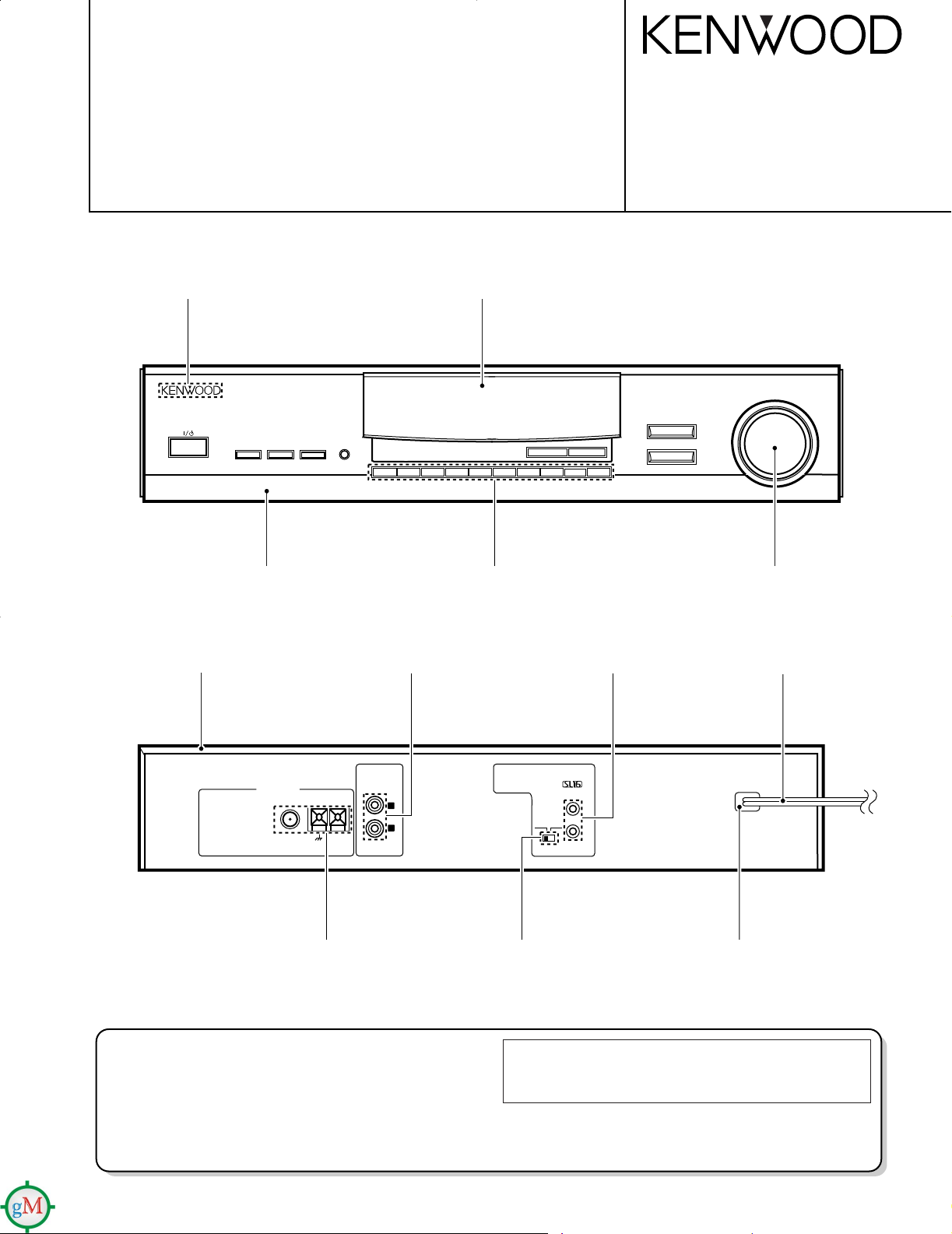
AM-FM STEREO SYNTHESIZER TUNER
HIGH BLEND
WIDE
NARROW
RF ATT
AUTO/MANUAL
+
10
/CLEAR
1
ACTIVE
RECEPTION IF BAND
TA/NEWS
PTY/
PTY SEARCH
RF ATT
DISPLAY
ANT A/B
MEMORY
AM
-
FM STEREO SYNTHESIZER TUNER
KTF-2010
BAND
P. CALL
DOWN UP
TUNING/MULTI CONTROL
3 4 5 6 7 8 9
0/CHARA
2
ON/STANDBY
ANTENNA
GND
AM
FM 75Ω
SYSTEM
CONTROL
ƒ
OUTPUT
R
L
SL16 XS 8
KTF-2010/3010
SERVICE MANUAL
Illustration is KTF-2010.
© 1998-1/B51-5407-00 (K/K) 2106
KENWOOD badge
(B43-0302-04)
Metallic cabinet
(A01-3559-01)
Panel
(A60-1336-02)
Phono jack
(E63-0068-15)
Front glass *
(B10-)
Knob
(K29-6882-03)
Miniature phone jack
(E11-0188-05)
Knob
(K29-6883-04)
AC power code*
(E30-)
Lock terminal board
(E20-0321-05)
How to reset the microcomputer
The microcomputer may malfunction (impossibility operation,erroneous display,etc.)when the power cord is unplugged and plugged
in again while the unit is in ON mode with the Key pressed or due
to other extern al causes.In this case,execute the procedure on the
right to reset the microcomputer and return the unit to the normal
condition
Slide switch
(S31-2132-05)
Power cord bushing
(J42-0083-05)
* Refer to parts list on page 18.
➀ Unplug the power cord form the wall outlet.
➁ While pressing and holding the (ON/STANDBY) key,
plug the AC cord into the wall outlet again
•Resetting the microcomputer clears the memory you entered and
returns in to the initial condition when the unit left the factory.
Page 2
TUNED
AUTO
kHz
MHz
STEREOSTANDBY ANT A BMEMOTA NEWS TP PTY
AR
RDS EON
** * ** * * *.
MW
LW
FM
HIGH BLEND
WIDE
NARROW
RF ATT
TUNING MODE
+
10
/CLEAR
1
ACTIVE
RECEPTION IF BAND
TA/NEWS
PTY/PTY
SEARCH
RF ATT
DISPLAY
ANT A/B
MEMORY
AM
-
FM STEREO SYNTHESIZER TUNER
KTF-3010
BAND
P. CALL
DOWN UP
TUNING/MULTI CONTROL
3 4 5 6 7 8 9
0/CHARA
2
ON/STANDBY
STANDBY indicator
RDS indicator
AR indicator
TA indicator TP indicator MEMORY indicator
PTY indicator Antenna A/B indicator
Kilohertz indicator
Frequency display
Preset channel display
STATION NAME display
Magahertz indicator
Receiving band indicatorSignal indicator
EON indicator
Tuning mode indicator
TUNED indicator
Reception mode indicator
NEWS indicator
1 2
0
9
&
3
4
5
6 7
8
*
@
!
%
^
#
$
Display
AUTO/MANUAL with the KTF-2010
KTF-2010/3010
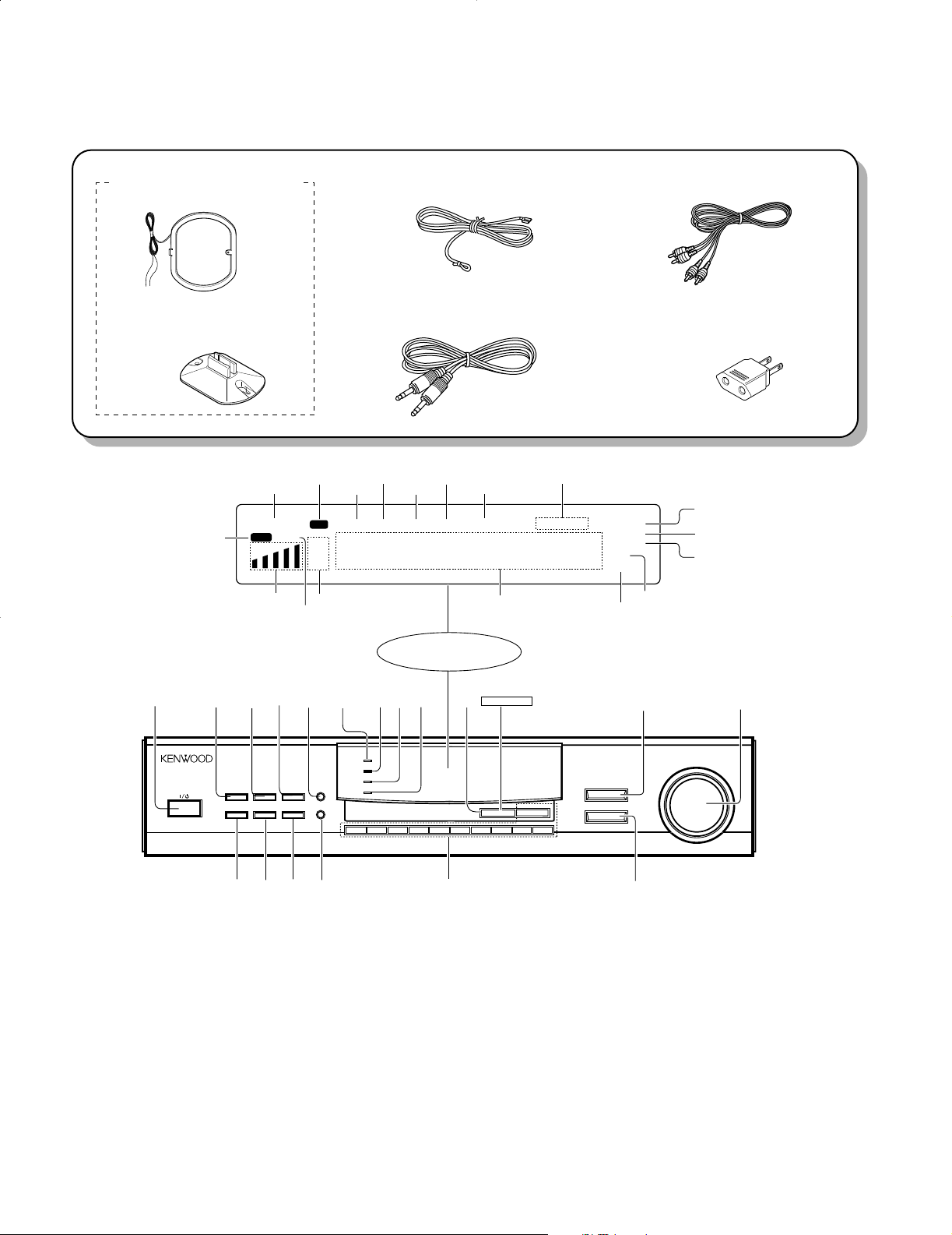
ACCESSORIES / CONTROLS
Accessories
• AM loop antenna ass'y........1
(T90-0195-05)
Controls
• Loop antenna stand
(J19-3645-05)
• Lead wire antenna...................1
(T90-0809-05)
• System control cord ................1
(E30-2733-05)
• Audio cord...............................1
(E30-0505-05)
• AC plug adapter......................1
(E03-0115-05)
(M type only)
11
POWER key
Press to turn on/off the power.
22
ACTIVE RECEPTION key(KTF3010 only)
Press to obtain the optimum reception conditions for the signals being received.
33
IF BAND key(KTF-3010 only)
Press to the intermediate frequency pass
band between WIDE(wide band) and NARROW(narrow band).
44
RF ATT(KTF-3010 only)
Press to minimize the RF reciprocal modulation and mixed modulation distortion when
there is an adjacent channel with strong.
2
55
ATT A/B key(KTF-3010 only)
Press to select the antenna when using 2
antennas.
66
HIGH BLEND indicator(KTF-3010
only)
77
WIDE indicator(KTF-3010 only)
88
NARROW indicator(KTF-3010
only)
99
RF-ATT indicator (KTF-3010 only)
00
AUTO/MANUAL key(KTF-2010)
TUNING MODE key(KTF-3010)
Press to select the tuning mode.
!!
BAND key
Press to switch the broadcast band.
@@
TUNING/MULTI CONTROL knob
Used for tuning broadcast stations, selecting
the program type and entering characters.
##
TA/NEWS key
$$
PTY/PTY SEARCH key
%%
DISPLAY key
^^
MEMORY key
Used for storing broadcast stations and
entering station names.
&&
Numeric keys
Used for storing and calling up broadcast
stations and entering station names.
**
P.CALL key
Press to recall a preset station.
Page 3
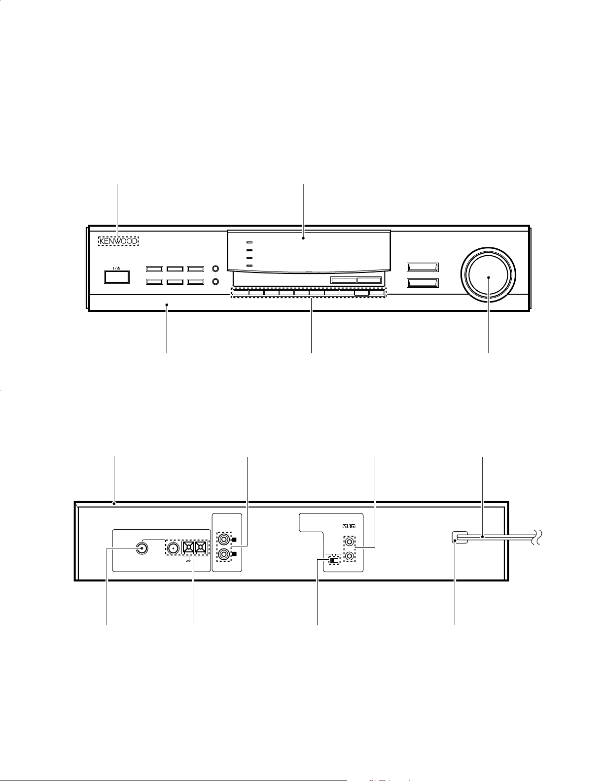
Illustration is KTF-3010.
HIGH BLEND
WIDE
NARROW
RF ATT
TUNING MODE
+
10
/CLEAR
1
ACTIVE
RECEPTION IF BAND
TA/NEWS
PTY/
PTY SEARCH
RF ATT
DISPLAY
ANT A/B
MEMORY
AM
-
FM STEREO SYNTHESIZER TUNER
KTF-3010
BAND
P. CALL
DOWN UP
TUNING/MULTI CONTROL
3 4 5 6 7 8 9
0/CHARA
2
ON/STANDBY
ANTENNA
GND
AM
FM 75Ω
BA
SYSTEM
CONTROL
ƒ
OUTPUT
R
L
SL16 XS 8
KTF-2010/3010
EXTERNAL VIEW
KENWOOD badge
(B43-0302-04)
Metallic cabinet
(A01-3559-01)
Panel
(A60-1357-02)
Phono jack
(E63-0068-15)
Front glass
(B10-2449-03)
Knob
(K29-6928-03)
Miniature phone jack
(E11-0188-05)
Knob
(K29-6883-04)
AC power code*
(E30-)
RF coaxial cable receptacle
(E04-0025-05)
Lock terminal board
(E20-0321-05)
Slide switch
(S31-2132-05)
Power cord bushing
(J42-0083-05)
* Refer to parts list on page 18.
3
Page 4

KTF-2010/3010
CIRCUIT DESCRIPTION
1. Test mode
1-1. Test mode with the main unit keys
a) Setting procedure
• While pressing the [P.CALL] key, plug the AC power cord
to the power outlet.
b) Cancellation
• Unplug the AC power cord. The initial setting will take
effect and the test mode will be canceled.
c) Description
Auto POWER ON
• When the AC power cord is plugged while pressing the
[P.CALL] key, the POWER will turn ON and all function
will be at the initial setting.
ALL LED ON mode
• When the AC power cord is plugged while pressing the
[P.CALL] key, all the LEDs will turn ON. Any key operation on the main unit thereafter will return the LEDs to normal.
Main unit key validity check
• Whether the main unit's keys are operable (valid) can be
checked. Regarding the keys whose display does not
change when they are used, their display will be made to
change.
0~9, +10 key operation
• Preset display : "– –" or "01" ~ "09"
When "0" key is pressed, 10 ch is called.
When "1" ~ "9" key is pressed, 1 ch ~ 9 ch is called.
When "+10" key is pressed, "1-" is displayed.
• Preset display : "1 -" or "10" ~ "19"
When "0" key is pressed, 20 ch is called.
When "1" ~ "9" key is pressed, 11 ch ~ 19 ch is called.
When "+10" key is pressed, "2 -" is displayed.
• Preset display : "2 -" or "20" ~ "29"
When "0" key is pressed, 30 ch is called.
When "1" ~ "9" key is pressed, 21 ch ~ 29 ch is called.
When "+10" key is pressed, "3 -" is displayed.
• Preset display : "3 -" or "30" - "39"
When "0" key is pressed, 40 ch is called.
When "1" ~ "9" key is pressed, 31 ch ~ 39 ch is called.
When "+10" key is pressed, "0 -" is displayed.
MUTE signal output
• The MUTE signal is not output.
No Display for FL
• Press the DISPLAY key to turn on/off the segments of the
FL.
Slide Switch Check
•The FL shows the Serial Code(XS8/SL16) by pressing the
MEMORY key.
•The FL shows the Channel Space(100kHz/50kHz) by
pressing the CH. SPACE key.
•The FL shows the normal mode by pressing the key and
the switch except the MEMORY and the Slide switch.
Display ex.
Serial Code Channel Space
XS8(or SL16) 100(or 50)
1-2. Test mode with serial communications
Refer to the test mode serial code table.
a) Setting procedure
• Plug the AC power cord and enter the TEST ON code.
8 bit serial communications : 71H
16 bit serial communications : 0C2FFH
b) Cancellation
• Enter the TEST OFF code (0CFEH) or unplug the AC
power cord.
c) Description
Other operations during the serial test mode
• The main unit's keys will be effective.
• The serial test code can be received even within 1 second
of POWER ON / OFF.
Required operations for the serial test mode
• The serial code for the serial test mode can be used to
check the operation of all circuits.
• The code entered during the serial test mode will become
valid regardless of the display mode.
• The following functions are available in the serial test
mode.
0 ~ 9, +10
AUTO (AUTO ST. / HI BLEND / MONO)
MEMORY
UP / DOWN (MANUAL SCAN unnecessary)
IF BAND, RF ATT
ACTIVE RECEPTION
ANTENNA A, ANTENNA B, PTY, DISPLAY, ALL LED
ON/OFF
• The MUTE signal is not output. This is for reducing the
input-output switching time during the measurement.
• When a valid serial code for the test mode is received, the
code identical to the code entered will be output.
• For checking the MUTE operation, MUTE has specific
codes.
MUTE ON/OFF
• To switch cyclically, enter the individual serial code. For
example for AUTO STEREO / MONO, enter the two
codes for AUTO STEREO and MONO.
• All the LEDs, turn ON / OFF is cancelled by inputting the
cancelling code and returned the LEDs to normal.
• All functions (including the test mode) will be initialized.
4
Page 5
KTF-2010/3010
CIRCUIT DESCRIPTION
1-3. Initial settings
a) Setting procedure
• If the unit has a back-up function, hold down the POWER
key and plug the AC power cord.
• During the test mode with the main unit keys and the test
mode with serial communications, the initial settings can
be obtained by unplug and plug the AC power cord.
b) Description
• All function (including test mode) will be initialized.
• The manufacturer's memory is always set in the preset CH
and area.
1-4. POWER ON startup
• Since the unit has a POWER key, no setting is required.
1-5. Initial status
POWER ON/OFF : OFF
TUNING MODE : AUTO
PRESET MEMORY : TEST FREQUENCY
LAST BAND : FM
FM LAST FREQUENCY : OVERSEAS 87.5MHz
/JAPAN 76.0MHz
AM.MW LAST FREQUENCY : CH SPACE 9K 531kHz
: CH SPACE 10K 530kHz
LW LAST FREQUENCY : 153kHz
LAST P.ch : [--ch]
RDS DISPLAY MODE : FREQUENCY DISPLAY
MODE
TA / NEWS / TA, NEWS : OFF
ACTIVE RECEPTION : OFF
ANT A/B : A
IF BAND : WIDE
RF ATT : OFF
SERIAL : XS8
1-6. Back-up status
POWER ON/OFF
TUNING MODE
PRESET MEMORY 1~40ch
LAST BAND
LAST P.ch
LAST FM FREQUENCY
LAST AM (MW) FREQUENCY
RDS AUTO MEMORY LIST
LAST LW FREQUENCY
ACTIVE RECEPTION
ANT A/B**
IF BAND**
RF ATT**
TA / NEWS / TA, NEWS*
PS STATION NAME*
* : E, T type
** : KTF-3010
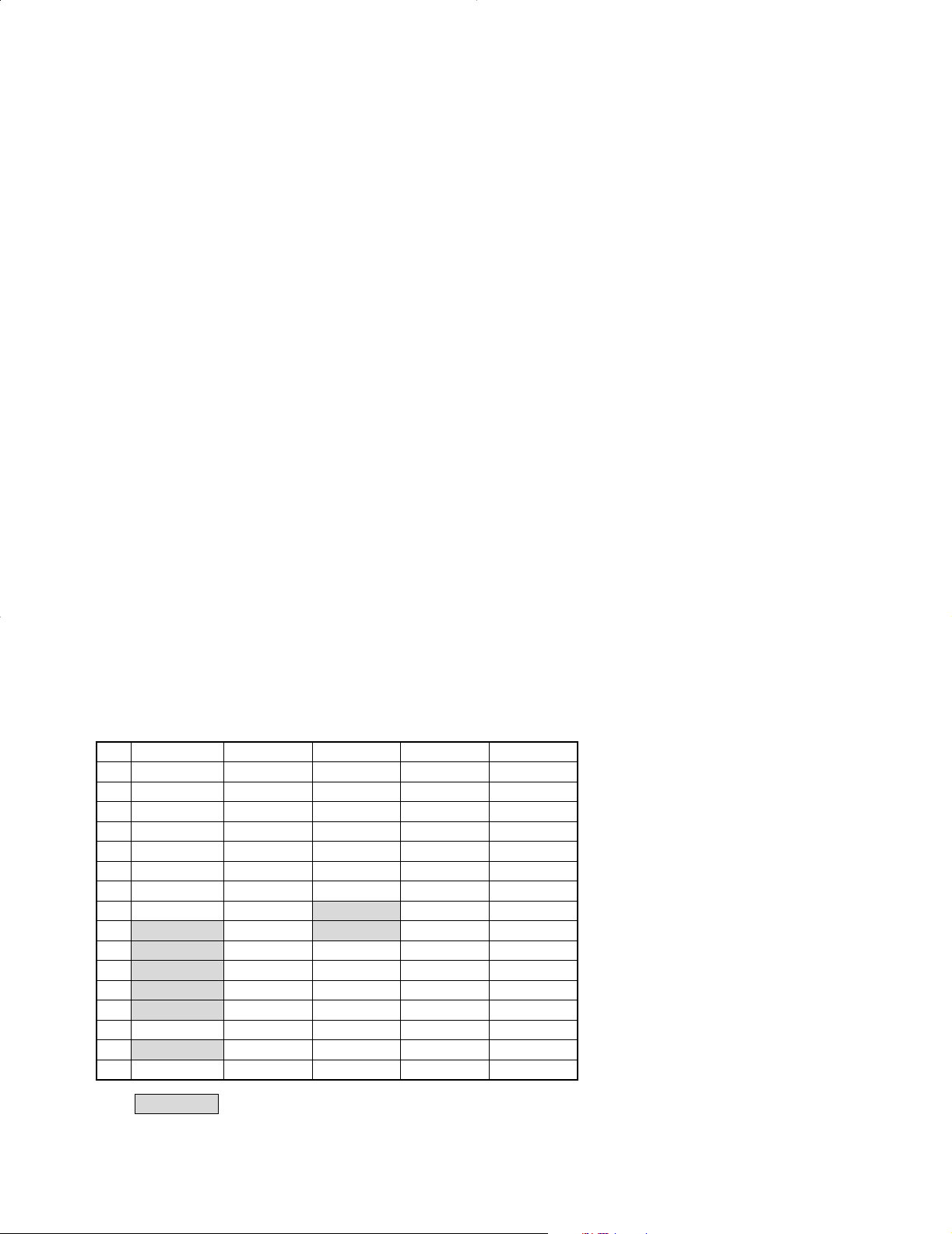
1-7. 16-bit serial test code (C2XXH)
8 9 A ..... F
0 POWER OFF 0 MEMORY
1 POWER ON 1
2 MUTE OFF 2
3 MUTE ON 3
AUTO STEREO
4
5 MONO 5 PTY
6 6 DISPLAY
7 7
Active reception OFF
8
Active reception ON
9
A RF ATT OFF +10
B RF ATT ON BAND FM
C IF WIDE
D BAND LW HI BLEND Initial setting
IF NARROW
E
F TUNING UP TEST ON
Note : Pls KT-2080/3080 service manual (B51-5128-00) on test frequency table and channel space table.
4
8 ATENNA B
9
BAND AM/MW
TUNING DOWN
: KTF-3010 ONLY
ATENNA A
All LED goes OFF
All LED goes ON
All LED ON : OFF
All LED ON :ON
TEST OFF
5
Page 6
KTF-2010/3010
ED 1
HIGH BLEND LED
ATT LED
NARROW LED
WIDE LED
Q1, 2
Q3, 4
Q10
ANTENNA A/B
RF ATT
IF BAND
HIGH BLEND
TUNING
SD
STEREO
L_LEVEL
S_LEVEL
TUNER MUTE
POWER
uPD780206GF031
u-COM
ENCODER
RESET
OSCILLATOR
SERIAL
CHIP ENABLE
XS8 / SL16
KTF-2010/3010
IC 9
KEY MATRIX
RDS DEMODULATOR IC
FL DISPLAY
PLL IC
IC 7
IC 2
S 26
CIRCUIT DESCRIPTION
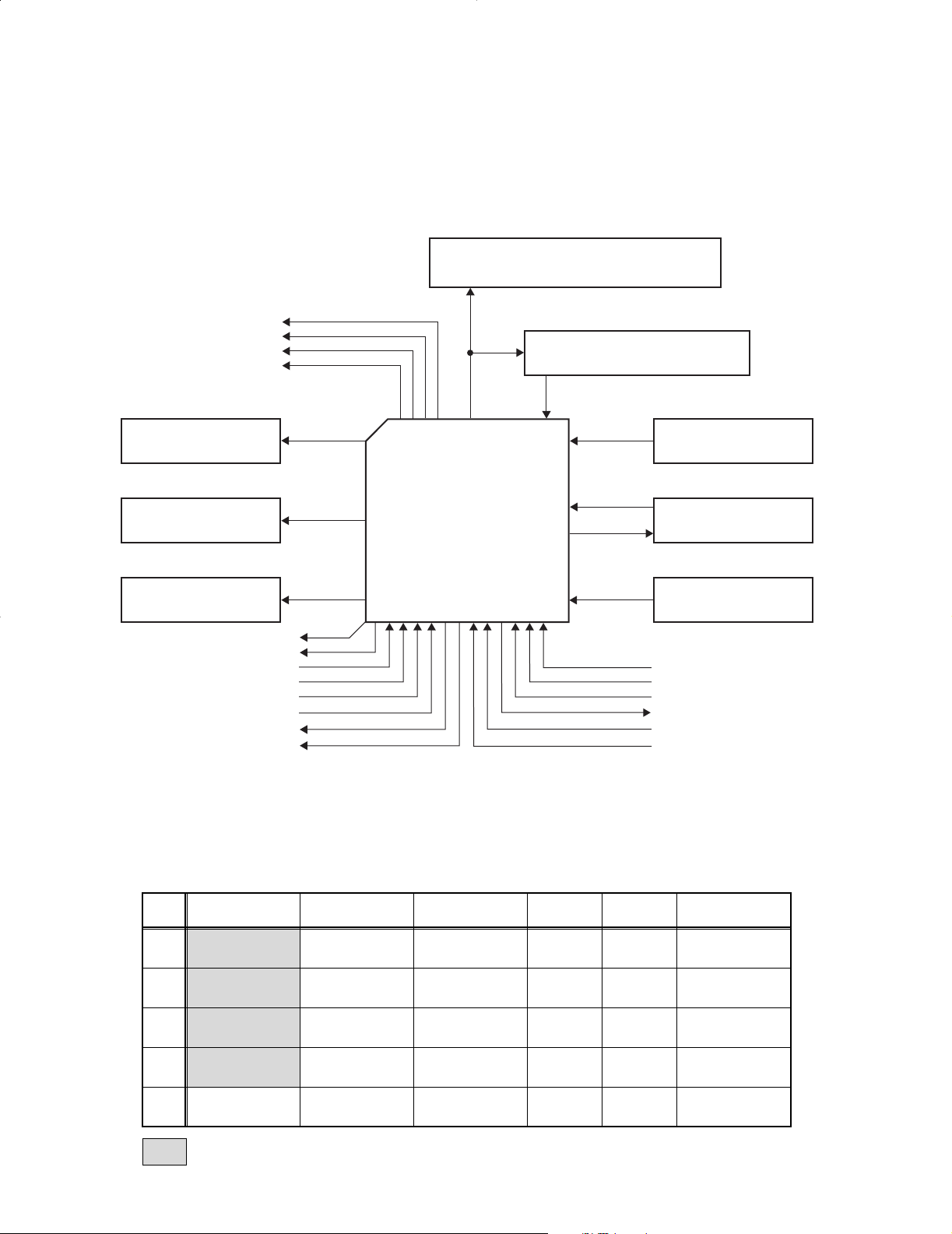
2. Microprocessor : µPD780206GF031 (IC9)
2-1. Pin connection
6
KEY MATRIX
KS1
(#82)
KS2
(#81)
KS3
(#80)
KS4
(#78)
KS5
(#77)
RECEPTION
means KTF-3010 ONLY
KR1 (#70) KR2 (#69) KR3 (#68) KR4 (#67) KR5 (#66) KR6 (#65)
ANT A/B ON / STANBY MEMORY 4 8 P.CALL
ACTIVE
RF ATT TA / NEWS 2 6 0 +10
IF BAND DISPLAY 3 7 - TUNING MODE
DSW0 (D56) DSW1 (D57) DSW2 (D58) - - -
PTY 1 5 9 BAND
Page 7

KTF-2010/3010
CIRCUIT DESCRIPTION
2-2 Pin function
Pin No. Pin Name I/O Descriptions
1 Vdd – Power supply(+5V)
2~8 – I No use
9 /CE I Chip enable L : CE detection
10 /RESET I Microprocessor reset L : RESET
11,12 X1,2 I Main clock oscillator
13 IC(Vpp) – Connect to VSS
14,15 XT1,2 I –
16 Vdd – Power supply(+5V)
17,18 – I No use
19 SBUSY I/O Serial busy signal
20 SDATA I/O Serial data signal
21 /HIGH BLEND I Hi blend L : HIGH BLEND
22 8/16 O XS8/SL16 selector L : SL16
23 /2080,3080 I model selector L : KTF–2010
24 POWER O POWER detection L : STANDBY
25 Avss – A/D converter gnd
26 PLL_DO I PLL DO
27 PLL_CE O PLL chip enable
28 PLL_DATA O PLL data detection
29 PLL_CLK O PLL clock
30 /T_MUTE O TUNER mute L : MUTE ON
31 – I No use
32 S_LEVEL I Signal level
33 N_LEVEL I Noise level
34 Avdd – A/D converter analog voltage
35 Avref – A/D converter standard voltage
36 RDS_CLK I RDS demodulator IC clock
37 RDS_DATA I RDS demodulator IC data
38,39 – I No use
40 Vss – Gnd
41,42 – I No use
43 /STEREO I STEREO pilot detection
44 /SD I SD pilot detection
45 TUNING O To stop noise level detection in tuning H : TUNING
46 Vdd – Power supply(+5V)
47~52 – I No use
53 /IF_BAND O IF BAND selector L : WIDE
54 /RF_ATT O RF_ATT selector L : ON
55 ANT_B O Antenna–B control H : ANT B
56 ANT A O Antenna–A control H : ANT A
57 ENC_B I Encoder counterclockwise detection
58 ENC_A I Encoder clockwise detection
59 HIGH_BLEND_LED O HIGH BLEND LED H : LED ON
60 WIDE_LED O WIDE LED H : LED ON
61 NARROW_LED O NARROW LED H : LED ON
62 ATT_LED O ATT LED H : LED ON
63,64 – I No use
65~70 KR6~1 I Key return 6~1
71~73 – O No use
74~76 SEG16~14 O FL segment output16~14
77 SEG13/KS5 O FL segment output13/key scan5(TUNER selector)
78 SEG12/KS4 O FL segment output12/key scan4
79 Vload – FL controller/driver pull down resistor
80~82 SEG11~9/KS3~1 O FL segment output11~9/key scan3~1
83~90 SEG8~1 O FL segment output8~1
91~100 GRID1~10 O FL grid output1~10
7
Page 8

KTF-2010/3010
X05-
CN4
+
Oscilloscope
Distortion meter
AC voltmeter
DC voltmeter
Dummy antenna
(B)
FIG. (a)
ANTENNA
GND
AM
FM 75Ω
BA
SYSTEM
CONTROL
ƒ
OUTPUT
R
L
SL16 XS 8
(A)
(C)
(D)
FM-MPX-SG
FM-MPX-SG
POLAR-SG
AM-SG
ADJUSTMENT
NO. ITEM
FM SECTION BAND : FM
1.
SENSITIVITY
(KTF-3010 ONLY)
2. DISCRIMINATOR
3. DISTORTION
DISTORTION
4.
(STEREO)
(KTF-2010 ONLY)
5. S.METER LEVEL
INPUT
SETTINGS
(A)
98MHz MONO
1kHz, ±40kHz dev
Approx. 20dBf
(ANT input)
(A)
98.0 MHz MONO
1kHz, ±40kHz dev
70dBf (ANT input)
(A)
98MHz MONO
1kHz, ±40kHz dev
70dBf (ANT input)
(C)
98.0MHz 1kHz,
±68.25kHz dev
Selector : L or R
60dBf (ANT input)
(A)
98MHz MONO
1KHz, ±40kHz dev
36dBf (ANT input)
OUTPUT
SETTINGS
(B)
Connect a DC
voltmeter
(X05-) to CN4.
(B)
(B)
TUNER
SETTINGS
AUTO : WIDE
RF ATT : OFF
98.0MHz
✜
✜
AUTO
98.0MHz
✜
ALIGNMENT
POINTS
L1
L6
ALIGN FOR FIG.
Maximum
amplitude
0V±30mV
L7 Minimum distortion
A1(FRONT
END)
Minimum distortion
Turn VR1 to fully
clockwise.
VR1
VR4
Adjust VR4 and
3 LEDs light on.
(a)
Adjust VR1 and stop
at the point where
ED1 (TUNED)
goes ON.
6. AUTO STOP LEVEL
(A)
98.0MHz MONO
1kHz, ±40kHz dev
25dBf (ANT input)
✜
VR1
(A)
98.0MHz 1kHz,
7. SEPARATION
±40kHz dev
pilot 6kHz dev
(B)
✜
VR3 Minimum crosstalk
Selector : L or R
70dBf (ANT input)
AM SECTION BAND : AM(MW)
Adjust VR2 and stop
at the point where
ED1 (TUNED)
goes ON.
1 AUTO STOP LEVEL
(D)
999kHz MONO
400Hz, 30% mod
28dBµ (ANT input)
999 kHz VR2
When TUNER PCB (X05-) is disconnected from main unit,connect PCB's GND (ANT shield plate) and main unit chassis
using aligator clip. Then, check TUNER PCB.
✣ TUNER SETTINGS
KTF-2010 : AUTO, 98.0MHz
KTF-3010 : AUTO : WIDE, RF ATT OFF : 98MHz
8
Page 9

1
IC2
(X05-484X-XX) (A/4)
IC7
IC8
A1 (W02-2512-05) KT-2010 (M1,X1) TYPE
(E,T1,E1,T2,J) TYPE
(M1,X1) TYPE
UN4112
2SB1218A(Q,R) or:Q8
2SC4081(R,S)
2SD1819A(Q,R) or:Q7
2SK302(Y,GR):Q5,6
DTA124EUA:Q3
DTC124EUA:Q1,2,4,32
S-806D-Z:IC8
SAA6579T
SAA6579T/R or:IC7
MC13028AM:IC6
LA3401:IC4
NJM4565D-D:IC3,5
LC72131:IC2
LA1266:IC1
(u-COM)
5.6V AVR
L.P.F
(FL)
-30V AVR
12V AVR
2SD1302(S,T):Q20-22
2SC1845(F,E):Q18,19
2SA992(F,E):Q16,17
2SC1923(R,O):Q12
2SC2785(F,E)
2SC1740S(Q,R) or:
Q11,13-15,28,38-41,44,48,53,59
UN4212
DTC124ESA or:Q10,33,35,43,50
DTA124ESA or:Q9,23,25,45
2SA1576A(R,S)
-B LINE
+B LINE
(1.1V)
2.4V
4.8V
4.8V
2.4V2.2V
2.4V
(2.5V)
0V
0V
(0.3V)
2.2V
4.7V
(4.8V)
2.3V
(0V) (2.3V)
0V
0.2V
0V
(11.7V)
0V
12.0V
(0V)
12.3V
(12.4V)
(2.8V)
2.9V
12.0V
(0.1V)
4.7V
(4.8V)
0V
0V
2.4V
(2.5V)
3.9V
(3.6V)
(1.1V)
2.5V2.5V
4.7V
5.4V
1.2V
3.9V
3.5V
2.0V
W: 0V
N:4.3V
3.5V
1.0V
4.1V
3.3V
1.3V
N: 0.4V
W:10.6V
N:11.0V
W:11.4V
4.1V
3.5V
7.6V
N: 0V
W:11.4V
N:10.6V
W: 0.2V
W:11.3V
N: 0.6V
3.1V
(2.2V)
2.3V
0.3V
3.9V
(3.6V)
2.4V2.4V
4.8V
2.9V
5.7V
5.8V
ON:11.4V
OFF: 0V
ATT
ON: 0V
ATT
ANT
A:3.5V
OFF:3.5V
B:10.6V
A: 0V
ANT
ANT
A: 0V
B:3.5V
ANT
108MHz
90MHz
FREQ
7.5V
1.4V
VT(VOLT)
1602KHz
531KHz
279KHz
153KHz
6.7V
1.1V
-31.4V
-35.7V
-34.6V
-16.6V
-25.4V
-25.4V
-0.6V
7.2V
2.8V
MW:12.4V
LW: 0.1V
B: 0V
X
BAND
VT VOLT
FM
B: 0V
MW
LW
AM
LW:12.4V
MW: 0V
5.2V
MW: 0V
LW:0.6V
LW:0V
2.9V
MW:
LW:0V
0.6V
MW:
LW: 0V
MW:0.6V
A:10.6V
4.8V
5.2V
5.1V
11.6V
4.8V
-32.0V
6.3V
-26.2V
2
3
6
4
5
5
4
3
6
7
8
9
10
2
R404 1K
+B
SIGNAL LINE
GND LINE
: AC230V~ 50Hz
: AC240V~ 50Hz
220-240V~50/60Hz
: AC110-120V/
(T,E)
(X)
(M)
T1
10
9
8
7
-B
VDD
+B
+B
W239
100P
C18
C88
220P
R8
33
R15 390
C80
330P
+B
+B
W100
C109
330P
R297
1K
R294
1 2W
C184 100P
C185
100P
C176
100P
1K
R108
100P
C195
R298
1K
R94
1K
1K
R103
R102
10K
C193
100P
+12V
+
C120
1u100
R296
100K
1K
R114
R150
100
C249 10P
+12V+12V
+12V
+12V+12V
1000P
X1
R208
R209
C236
C235
C237
220
R218
47K
C33
C35
+B
+B
+B
C143
SW
C72
6.8K
R73
C38
5
7
C219
0.01
C220
330P
R96
10K
C65 0.01
1
L9
R191
1K
+12V
+4.8V +4.8V
+12V
PLL.DO
CH.SPACE
CE
Q28
W67
+12V+12V+12V+12V+12V
+4.8V
+12V
+5.6V+5.6V+5.6V+5.6V+5.6V
+5.6V
+5.6V
+5.6V
+5.6V
+B +B
+B
+B +B
-30V-30V-30V-30V-30V-30V
+5.6V
+12V
+12V
R196
1K
+12V+12V
+5.6V
+5.6V
+5.6V
VCC
+5.6VVCC
+5.6V
+B
C3
C8
Q59
1/4W
Q49
4.8V AVR
(PLL)
+B
+B
+B
+B
+B
+B
+B
MW/LW
W52
+B
+12V +12V
0.01
C62
-30V
1/4W
+B
+B
X
F
C39 0.01
R192
1K
1
R236
1
R235
Q60
1K2.2K
UNLOCK
PHASE DETECTOR
CHARGE PUMP
POWER
11910
8
7
6
DATA SHIFT REGISTER LATCH
+12V
+12V
+12V+12V
C19
+
C89
10u35
+12V
+12V
C67
15P
7.2MHz
C82
12P
C83
10P
12
13
C66
0.01
+
C166
10u35
1K
R195
R89
C68
12P
R88
100
C64
18P
C71
100P
330P
C70
C218
1K
R200 1K
W130
1K
W131 W207W138W83
220P
C69
C63
100P
+B
+12V
+B+12V+12V
VDD
VDD
VDD+4.8V
RESET
DETECTOR
ON
1/16,1/17 4bits
SWALLOW COUNTER
14
22
PLL
2
5
4
123
REFERENCE
DIVIDER
R295
330
R206
330
C206
100P
R225
1
C167
100P
0.01
R202
C168
0.01
0.01
R293
820
D27
100P
W119
X
X
X
100P
Q29
820P
C233
100P
R180
100
C241
100P
+
C165
100u16
R93
330
R92
4.7K
+
C73
47u16
47u16
C175
C234
R137
3.3K
R136
220
D11
C222
21
20
C246
100P
C247
100P
C248
10P
C30
330
0.01
C9
1K
R87
1K
R289
W62
W53
2
1
W91W110
6
R43 100
W111
P5
VP1
FM
+B
820
R213
180
R214
Q51-53
( u-COM,+5.6V)
AVR
(FL-30V)
AVR
Q33,50
J6
W86
W70
: 2SC2714
TR3
TR2
TR1
R12 P194AIFT :
KV1440
SVC212
1SV225
or
: HVM27D1~D3
R76
68K
AMP
S METER
Q16-19
Q12~15
IF AMP
FET : 2SK302
: 2SC2715
: 2SC2996
VR4
1000P
C221
UNIVERSAL COUNTER
16
17
18
19
20
15
1/2
DIVIDER
12bits PROGRAMABLE
FM
FM
AM
GND
L5
D14
AM
+B SW
Q23
47P
100u10
C148
0.01
C149
W29
C154
2.2u50
1K
R187
R185
47K
OSC
BUFF.
OSC
FM-IF
D
D60
4.332M
X4
R186
1K
2.2K
R153
22P
C152
C151
C81
W134 W116
33P
C44
0.022
C56
C55
0.022
RF
REG.
33P
C76
0.47u50
R19
220
R95
C75
2.2u50
C74
0.022
R91
SYSTEM
DEMODULATOR
RDS DATA
REGENERATION
AND SYNC
CLOCK
VOLTAGE
REFERENCE
QUALITY BIT
GENERATOR
SELECTOR SWITCH
TESTLOGIC AND OUTPUT
DIFFERENTIAL
DECODER
CLOCKED
COMPARATOR
SYMBOL
DECODER
BIPHASE
FIXED DIVIDER
VARIABLE AND
CONSTAS LOOP
OSCILLATOR
AND
DIVIDER
FILTER
RECONSTRUCTION
57KHz
BANDPASS
(8th ORDER)
FILTER
ALIASING
ANTI-
270P
C153
560P
9
10
Q24
R90
1K
24
23
22
21
1
2
3
4
D30
17
D36
R267
47u16
D32 D31
Q48
Q47
Q49
C205
22K
R274
Q50
Q33
AVR
R204 390
R203 390
100u10 10u35
C242
C169
R207
1K
122021222324252627
W7
CN1
S1(M)
T1
AC220~240V
AC110~120V
2
1
C162
+
47u50
D28
D26
D25
C128
C164
2200u2547u50
C173
D35
D34 D33
R215
10K
R290
100
75K
1/4W
Q31
Q30
2.2K
4.7u35
15K
R266
2
1
9
10
11
121314
15
16
18
OUTIN
GND
19
SW
+B
MAIN
(PLL)
R106
1K
1K
R101
R104
R300
R199 1K
R201 1K
4
3
R220 10K
1K
R219
RESET
IC
RF ATT
IF.WIDE
PLL.CE
PLL.DATA
PLL.CLK
RDS.CLK
TUNNING
SD
N.LEVEL
S.LEVEL
STEREO
MUTE
POWER
SL16/XS8
/HIGH BLEND
S.DATA
S.BUSY
CE
GND
+5.6V
-30V
F1
ANT A
ANT B
RDS.DATA
F2
CN2
R107
1K
10119
6
7
8
13
14
15
16
3
4
1
2
5
12
D42
C180
0.01
C210
100P
Q19
Q16
Q17
Q18
18K
LEVEL
S METER
FM
470
R66
R65
1K
R64 220
220
R63
R61
0.01
R62
C29 0.01
R56
1K
0.01
R50
R54
R49 470
Q12
CF3
0.01
R57
220220
R51
R53
2.2K
1.5K
R52
0.01
C31
C32 0.047
R59
1.2K
1K
R58
1.5K
R55
Q13
Q14
Q15
Q7,8
W89
R212
1000P
C170 22u16
R210
R211 4.7K
Q52
Q53
10
1.8K
R270
D64
D43
Q51
C172 22u16
R271 10K
W145
10
4.7K
18 1516 121314 11 10 819 9 675 43
R216
220 R217
47K
C171
0.01
Q11
R48
10K
D10
R34
3.6K
R37
C25
0.01
3.6K
R38
Q9
Q10
IFT
D9
D8
IF BUFFER
R46
100
R288
R47 1.8K
1.8K
R45
C201 0.01
R41 1.8K
1.5K
Q8
Q7
Q6
R39 510
0.01
C26
D7
R36
C24
0.01
R32 7.5K
100100
R35 680
R30 39012K
R31
0.01
C22
W101
R28
CF2CF1
R40 1.8K
C28
0.01
R287
1.5K
D5
C20 0.01
R25 100 560
R26
R29R27
C21
0.01
OSC
8
6
7
5
4
3
2
1
R18
220
47K
R17
C15
1000P
R22
470
LW SW
BAND SW
Q25
L4 10uH
22P
6P
C43
C41
2P
C42
4.7K
R70
W78
W75
L3
Q22
Q21
Q20
W77
W69
W61
100K
2.2K
R72
2.2K
R71
R69
22K
C27 0.01
R42
2.2K
R33
220
0.01
C23
D6
R268
220
C194
W106
510
R44 100
B
A
(NARROW)
IF AMP
SW
WIDE/NARROW
4
D13
D12
1 H
L2
R74 100K
R75 100
C37 15P
0.047
C209
1000P
SENSITIVITY
AMP
RF
(ANT A)
ANT SW
(ANT B)
ANT SW
ATT SW
RF
C12
DISTORTION
R10
33P
680K
D1
D2
RF AMP
MIX
OSC
BUFFER
C8 0.022
R4 33K
R3 33K
R6 10KC11
D3
0-8P
L6
R9 10K
C13
8P 27P
C14
C15 22P
1K-2.2K
2-6P
C16
10K
R8
100K-
R11
C17
100P
330
R12
100
R7
TR3
TR2
TR1
FET
C10
0.022
OUT
+B
IF OUT
560K-1.5M
R5 R13
470
L5
L4
C5 1000P
4P
C4
C2 12P
C6 3P
C7 22P
C3 0-8P
C1 0-8P
100K
R1
R14
390
C9
0.022
R2
C B I/F
21
0-150
VT
GND
GND
ANT
ANT
C13
R21
470
Q5
D4
47K
R20
C17 1000P
R23 47
R24 51K
47P
C16
C14
L1
1K
R100
1K
R99
3
C10
1000P
R12
100K
2.7K
R11
1000P
C11
1000P
C6
Q4
Q3
R16
270
D3
C12
L3
L2
L1
390
R10 R9
1.8K
C7
1000P
C2
1000P
R13
100K
R14
100K
R98
1K
1.8K
R2
Q2
Q1
D1
J2
J1
(ANT B)
(ANT A)
D2
C5
1000P
R5
470
1000P
C1
1000P
390
R3
R1 1.8K
390
R4
C4
1000P
1000P
R6 470
X
X
X
X
X
X
X
X
X
X
X
X
X
X
X
X
XXXX
X
X X
X
X
X
X
X
X
XX
X
X
X
X
X
X
X
X
X
X
X
X
X
X
X
X
X
X
X
X
X
X
X
X
X
X
X
X
X
X
X
X
X
X
X
X
X
\M+183CA
(
)
)
(
+
()(
)
(
)
(
)
)
(
+
+
+
(
)
)
(
+ +
+
+
+
+
()()()()()()()()()(
)
(
(
(
(
)
)
)
)
+
+
(
)
(
)
2
3
4
5
6
7
A BDFHJCEGI
Page 10

KT-2010 (E,T1) TYPE
KT-3010 (E1,T2) TYPE
IC6
KTF-2010/3010 (1/2)
A1 (W02-2509-05)
IC4
IC1
A
X
FM
AM
AM STEREO
MUTE
AM
Q56
Q55
DECODER
AM
STEREO
+B SW
AM STEREO
Q46
D17
Q44
Q45
OUTPUT
HZS5.1S(B2)
RD5.1JS(B2) or:D36,64
HZS11N(B2)
MTZJ11(B) or:D31
S5688B:D25,26
MA111:D11
HSS104A
1SS133 or:32-35,37,38,40-43,60,65
D5-10,12-19,23,24,27,28,30,
SVC212(2.3):D4
1SS268:D1-3
2SC3940A(R,S):Q49,51,52
2SD2061(E,F):Q47
2SA1534A(R,S):Q46
2SK364(GR,BL):Q36,37,57,60
2SA1175(F,E)
2SA933AS(Q,R) or:Q30,31,42,55,56
2SK246(Y,GR):Q29
2SA954(L,K):Q24
Q57
Q32
D18
11.4V
(11.5V)
5.3V
(5.2V)
3.2V
3.2V
5.4V
(5.3V)
3.2V
3.2V
11.3V
(11.4V)
5.0V
(0.1V)
2.8V
(2.9V)
2.8V
(9.3V)
2.8V
(5.2V)
2.8V
(2.9V)
0.1V
(8.0V)
1.0V 1.3V
0V
1.0V
1.0V
0.3V
1.0V
0.4V
(12.4V)
0V
(2.1V)
1.5V
(1.1V)
2.5V 0V
(3.7V)
2.3V
(2.6V)
1.5V
(2.1V)
1.6V
0.2V
3.2V
(2.2V)
2.8V2.4V
(2.5V)3.9V
(3.8V)
0V
12.3V
(12.4V)
(12.4V)
12.3V
1.5V1.0V
8.7V
1.0V
0.6V
1.8V
1.8V
OFF:4.8V
ON: 4.2V
12.4V
5.1V
ON: 0.7V
OFF:-2.8V
(7.5V)
2.8V
7.3V
4.7V
(2.5V)
3.4V
3.2V
1.2V
1.7V
: 0V
TUNED
1.2V
1.5V
NO
C19
C39,
90
W84
R105 1K
7
6
E20-0321
J2CF4
L72-0546
L72-0120
L72-0551
L72-0120
CF3
J2
E70-0052
L72-0546
L72-0536
CF3,4
1W
1W
90,219,221
C39,53,62,
15
R7
10 1/4W
+12V
+12V
+12V
8.2K
R402
R401
100
C135
C86
0.01
R86
1K
R299 1K
100P
330P
C19
YES
NO
195
C193,
100P
NO
C218
220P
C218C80
YES
NO
402
R401,
W237
W27
W26W11
75u FM100K/AM10K
FM50K/AM9K
DE-EMPHASIS
(J)TYPE ONLY
+
47u16
R269 15KC197 0.01
+12V
C129
100P
1/4W
1/4W
W41
C144
0.33
R182
2.2K
C145
0.33
R181
2.2K
C150
0.47
XL16
XS8
120K
R130
680P
75K
680P
75K
NO
R401,
402
W11,22,
26,27
NO
YES
NO
R101,105-107,121,138,139,
R82 R83R54
10
NO
73
R69-
YES YES
142,143,208,209,281,282,300102,111,112
C80,101, R43,117,118,127,
128,131-133,188
NONO
C52C9
YES
114,129-132,222
C40,107,113,
NO
YES
E,FHB,C,,A
ABB.
E1
UNIT
NAME
2-71
YES
0-01J
U.K T2 0-52
DESTINATION
COUNTRY
EUROPE
KTF-3010(X05-484X-XX)
JAPAN
D
YES
NO
YES560P
NO
YES
12P
5P
C14
2P
1P
C12
W4
YESNONO
T1L3
L07-2086
CF2 D11
YES
A1
W02-2509
L39-1328
L39-1325
S1,27W87,
101,231
NOYES
134,153
W58,116,W52,62,70,83,
131,136,207
NO
NO
84,130,150,151
W7,46,66,72,
NO
111,145,147,148
W22,50,51,86,91,110,
IC5
YES
36,37
Q34, Q35,
5125
Q20-22,
NO
149
R148,
R210
YES
75K
YES
NO
YES
W02-2510 NO L07-2088L39-1328YESYES
YES
NO
75,77,78
W61,69,
YES
NO
NO
YES
NO
100
100K
4.3K
4.7K
141
R140,
36K
R123
15K
18KNO1K
NO22
136,137
R27-29,
270
120
R36,37
100P
C53
0.047
C13
100P
390P
+5.6V
W71W117
R184
4.7K
R183
1.2K
C223
0.01
H
E
R117
12K
+12V+12V
+12V
+12V
+12V
+12V
-30V
+5.6V
+5.6V+5.6V
+5.6V+5.6V
+12V
+12V
+30V
-30V-30V
-30V
100P
C115C116
R154
R156
R157
R155
0.01
R198
100K
R262
CONTROL
39K
100P
47u16
C142
C141
C140
R174
C198
R171
R172
R67
C91
R133
R242
+12V
+12V
L07-2084
L07-2082
T1L3
L39-1328
L39-1325
L39-1328
NO
YES
D11
NO
CF2
W02-2512
W02-2509
A1NOIC5
YES
NO
27
S1,W83 131,
136,207
NO
YES
YES
NO
YES
NOYES
NO
YES
75,77,78
W61,69,72W66,
62,70
W52,
NO
NO
YES
YES
116,134,145,147,148,153
W50,51,58,86,91,110,111,
NO
W46,84,87,101,
130,150,151,231
NO
YES
YES
NO
W7
51
Q35,
NO
YES
NO
NO
NO
YES
36,37
Q34,Q20-22,
25
220
R210
4.7K
149
R148,
NO
YES
137
R136,R117,118,127,
128,131-133,188
YES
NO
18K3.3K
R83R82
NO
YES
NO
R69-
73
56
22
R54
YES
R43
NO
123,138-143,208,209,281,282,300
R27-29,36,37,101,105-107,121,
YES
NO
102
C101,
YES
111,112
C53,
4700P
C52
NO
YES
W4
YESC9YES
NO
,H,
+
C138
10u16
+
C139
10u16
+
+12V
+12V
+12V
+12V +12V +12V
+12V
C110 100P
+
C227
47u16
C228
100P
VR1
+12V+12V
+12V
+12V
1M
R179
C126
1u50
W12
R334
22K
R332
100K
R330
2.2M
1
2
3
5
687
4
16
15
14
12
11910
13
BLEND
HIGH
C127
0.022
AGC
VCO 1/8
C136
10u16
C137
0.47
R175
680K
R283
47
C36
AM STEREO
DETECTOR
SIGNAL
DETECTOR
QUALITY
PILOT
DETECTOR
IF
AMP
10K
+
10u16
3300P
D15
C159 10P
C158 33P
0.22
+
C160 R170
C199 3300P
R173 10K
47
X3 3.6MHz
+
0.47u50
X
1.2K
R135
21
100P
R60
C245
100P
R84
20
C45
0.047
C240
24K
R176
C124
100P
C125
100P
R152
5.6K
R151
1K
220u16
C163
+
100P
C217
R178
22
R177
3.9K
+
C161
47u16
L14
C108
R112
W231 W87
22K
C90
1200P
2K
R113
C85
1000P
18
S2
C130
100P
C132
100P
C131
C111
C112
C9
3P
L4
RF AMP
0~100
FET
R4
L6
7
C11 18P
+B
0.022
C22
C19
6
OSC
R14
330
R3 100K
L3
0.022
C21
0-100
IF OUT
TR1
IFT
MIX
DISTORTION (ST)
DISTORTION
DISCRIMINATOR
P8
CH. SPACE
50u
16
R147
220
220
R146
SW
DE-EMPHASIS
(DISTORTION)
NARROW SW
SEP
C4
C2
15P27P
C1
R2 100K
C3 22P
R5 33K
100
R8
0-6P
AUSTRALIA
GENERAL MARKET
U.K
EUROPE
COUNTRY
DESTINATION
KTF-2010(X05-484X-XX)
IFT : R12 P194A
: SVC212D1~D4
TR2
TR3 : 2SC2715
: 2SC2996
: 2SC2714:90~140hfe
: 2SK302
TR1
FET
R7
C7 4-10P
680K-1M
C8 2-8P
D2
10P
C6
L5
R6 33K
2/2
X05-B/4
-CN3
R12
R126
R82
330P
113,114,129-132,200
C12-14,40,62,65,107
DE,FNOC,B,A
2-70
0-51
0-21
0-71
NAME
UNIT
X1
M1
T1
E
ABB.
SYSTEM
R80
1K
2.2K
3.9K
W46
R281
3.9K
3.9K
R282
W148
W147
C106
6800P 6800P
C105
R134
1.2K
TR3
TR2
R15
220K-
820K
BUFFER
C16
27P
C18
4P
10K
OSC
10P
C15
D4
R11 10KC13
39P
1K-2.2K
C17 22P
R13 10K
L7
0-6P
R16
C14
VT 5 OUT
R17
330
100P
C20 0.022
8
W50
Rch
Lch
J3
VREF
TUNED
CN4
Q38~41
MUTE
AMP
POST
Rch
Lch
390P 390P
R149 R148
Q38
Q39
Q41
Q40
150
R145
R144
150
2.2K
2.2K
2.2K
2.2K
W51
C114
+
10u35
+
C113
10u35
C119
MUTE
DRIVER
R159
10K
4.7K
R158
220K
4.7u35
+
C92
W66 W72
2.2K
R110
10K
R111
100K
R164
C123
0.1u50
SW
NOISE METER
L13
6.8m
220K
R166
W150
C
+
10u35
+
10u35
R124
D19
W151
R125
C100 C99
R127
2.2M
Q37
10u35
C103
0.022
C40
C104 560P
R121
47K
R123
C97
1u50
R119
47K
Q35
15K
R131
2.2M
+
+
1u50
C94
1u50
C96
100K
R116
R81
C46
4.7u35
C50 2.2u50
C51 0.01 0.22u50
C54
4.7K
R79
1K
3.3u50
C48
C47
2.2u50
R78
10K4.7K
R77
10K
VR2
R197
10K
R160
Q42
D65D23
2.2M
DATA
BUSY
SGND
GND
J4
D41
D40
330
R263
R261
330
R264
100K
R194 100K
R193 100K
C146 220P
C147 220P
D38
D37
21
20
R188
10K
W22
S27
19
L12
L11
(1/2)
IC5
14-
2
3
+
IC5
(2/2)
6
5
8
+
- 7
456kHz
X2
R115
5.6K
SW
MONO
C98 0.1 R120 1K
C95
0.22u50
IF
BUFF.
IF
BUFF.
POST
AMPDRIVER
LED
VCC
Q.D
S METER
NARROW
S METERDET
AM-IFAGCMIX
L6
W58W153
C52
AM
AUTO
LEVEL
STOP
C49 0.047
D16
1K
R169
W85
AMP
BUFFER
(1/2)
IC3
D24
Q43
13
11
+
4
3
1
-
2
NOISE
METER
AMP
7
6
5
8
-
+
IC3
(2/2)
0.1
C122
1K
R163 R162
2.2K
470P
C121
R161
4.7K
R165
R168
5.1K6.8K
R167
2.2M
R132
Q36
R129
120K
C101
330P330P
C102
2.2M
R128
R122 4.7K
VR3
R1 33K
R10
C10 220P
C12 1P
D3
D1
L1
L2
ANT
1
GND
2
GND 4
GND 3
C5 3-7P
C93 0.01
Rc
RcRa
1K
80K
Rb
Rb
80K
FM AM CHANGE
MUTING
DECODER
VCC ON
MUTING
MUTING CONTROL
FM AM CHANGE OVER OUTPUT
MUTING
SWITCH
STEREO
19KHz 0
FF
19KHz 90
FF
38KHZz
FF
FFFF
TRIGGER
VCO STOP
CIRCUIT
SYMMETRICAL
REACTANCE
LAMP
DRIVERDET
PILOTPHASE
COMPARATOR
OSC
REG
VOL
FM MPX
SYSTEM IC
FM/AM
5.1K
R265
10K
R85
L7
C58 47u16
C57 0.01
12
14
5
R83
C61 10P
C60
0.47u50
C59
0.1u50
20
19
171618
141513
5
6
897
12
11
10
131214
19
161517
18
20
21
22
11
10
978
4
5
6
3
2
1
R68
10
CF4
1.2K
47K0.01
LEVEL
STOP
FM AUTO
330
VR1
3.3K
VR4
C34
0.01
1
R190
100
R189
100
5.6K
5.6K
R143
220
R142
220
C107
47u16
5.1K
R139
6.8K
R138
R141 R140
X
X
X
X
X
X
X
+
X X
X
X
X X
X
X
XX
X
X
X
X
X
X
X
X
X
XX
X
X
X
X
X
X
X
X
X
X X
X
X
X
X
X
X X
X
X
X
X
X X
X
X
X
X
X
X
XX
X
X
X
X
X
(
)
)
(
)
(
(
)
)
(
+
+
+
+
+
+
+
++
)
(
(
)
(
)
)
(
(
)
+
+
)
(
)
(
(
)
+
+
TK M O Q SL N P R
MODE CARRIER
FM 98MHz 1kHz STEREO 67.5kHz 7.5kHz(Pilot) 60dB
AM 1000(999)kHz 400Hz MONO 30% MOD 60dB
FREQUENCY DEVIATION
MODULATION
CAUTION: For continued safety, replace safety critical components only with manufacturer's recommended parts (refer to parts list). indicates safety
critical components. For continued protection
against risk of fire, replace only with same type and
ANT INPUT
rating fuse(s). To reduce the risk of electric shock,
leakage-current or resistance measurements shall
be carried out (exposed parts are acceptably insulated from the supply circuit) before the appliance is
returned to the customer.
The DC voltage is an actual reading measured with
a high impedance type voltmeter as the AM/FM signal generator is specified to the conditions as
shown in the list below. The measurement value
may vary depending on the measuring instruments
used or on the product. The value shown in ( ) is
actual reading measured in the AM made.
KTF-2010/3010
Y07-3842-70
Page 11

U V X Z AB ADW Y AA AC
(X05-484X-XX) (B/4)
ED1
IF BAND
PTY/PTY
2
S13
(
KS2
)
(
(
KS5
)
1
(X05-) (C/4)
WH3
E3
11
22
CH
SPACE
X
X
Q58
D59
E4
S7
3 3
KS4
)
RECEPTION
DS0
X
D56
DS1
X
D57
DS2
X
D58
ON/STANDBY
2
(
KS3
)
ACTIVE
SBARCHDISPLAY
3
S14
7 6 5 4
0
W162
SAA6579T
X
TUNING
W210
X
MODE
S21
+10
S25 S24
3
2SA1534A
2SA954
2SA992
a
h
f
g
e
r
p
2SC1845
2SC1923
2SC3940A
d
(9G~2G)
2SD1302
4
NARROW
HIGH BLEND
(X05-) (D/4)
S26
DOWN
UP
5
TUNING
MULTI CONTROL
3
2
1
6
KTF-2010 (X05-484X-XX)
E2
DESTINATION
COUNTRY ABB.
X05-A/4
-CN2
1/2
A
7
U.K. T
AUSTRALIA
KTF-3010 (X05-484X-XX)
DESTINATION
COUNTRY
EUROPE
U.K.
JAPAN
UNIT
NAME
EEUROPE
2-70
0-51
X
0-71
MGENERAL MARKET
0-21
UNIT R241,249-255,
NAME
ABB.
E
2-71
T
0-52
J
0-01
WH2
R240
YES
R240
NO
E1
3
2
1
IC9
Q54
Q58
D39,44,47-50,67
D46,51-59
ED1
R241,249-254,
273,301
NO
273,301
YES
: UPD780206GF031
: 2SD1819A(Q,R) or 2SC4081(R,S)
: DTA124ESA or UN4112
: MA111
: 1SS133 or HSS104A
: B30-2493-05D61-63,66
: 10-BT-202GX
D59D57 D58D56R255
NONOYES
YES
YES
NO
D58,
61-63,66
NO
NO
YES
D59
NOYES
NO
YES
YES
D57
D56
NO
YES
NO
YES
YES
W162,
210,228
66
NO
RF ATT
IDE
W162,D61-63,
NO
YES
W181-184,209
223-226
YESNO
X
D66
X
D61
X
D62
X
D63
C187 390P
C186 390P
W181-184,209
223-226210,228
NO
C230-
232
R273 270
R249 270
R250 270
R251 270
C230-
232
S3-6
YESNO
(
)
RF ATT
S4
TA/NEWS
XX
S8S9S10
1
S12
S16 S15S17S18
9 8
S20 S19
S23
j
k
b
m
n
c
W181
W182
W183
W184
+B
-B
S8-9S3-6
YES
NOYES
NO
S8-9
Q58
YES
NO
NO
KS1
ANT
XXXX
MEMORY
P. CALLBAND
XXX
XXX
XXX
XXX
GND LINE
+B LINE
-B LINE
A/B
S11
S22
W226
W225
W224
W223
Q58
NO
YES
9G10G 8G 7G 6G 2G 1G5G 4G 3G
a
STANDBY
EON
RDS
C226
1000P 22
D53
(
)
KS3
D54
(
)
KS4
D55
(
)
KS5
R286 100K
R285 100K
R284 100K
R324 100K
R234 100K
R233 100K
C189 220P
C190 220P
CN3
(
70
(
69
(
68
(
67
(
66
(
65
h
(
(
(
(
(
(
)
)
)
)
)
)
W209
R255 100
X X
ANT.A
-24.1V
)
80
)
78
)
77
)
76
)
75
)
74
R253 100
R254 100
XXX
ANT.B
R333
0.5V
0.5V
0.5V
0V
0V
0V
0V
0V
0V
-24.1V
-24.4V
-15.8V
-27.2V
-24.4V
0V
4.1V
0V
4.8V
4.8V
4.6V
0V
4.6V
RF ATT
S3S5S6
)
(
70
)
(
69
)
(
68
)
(
67
)
(
66
)
(
65
R275 100K
R276 100K
R277 100K
R278 100K
R279 100K
R280 100K
R327 100K
R326 100K
R325 100K
R248 100K
R247 100K
R246 100K
220
220
R256
R257
10K
R258
R259
10K
k
AR
j
f
AM
m
MW
g
LW
b
FM
nprec
9G
)
100
-15.5V
D51
)
KS1
D52
)
KS2
-15.5V
SEG11/KS3
VLOAD
SEG12/KS4
SEG13/KS5
SEG14
SEG15
SEG16
NC
NC
NC
KR1
KR2
KR3
KR4
KR5
KR6
NC
NC
RF ATT
NARROW
WIDE
HIGH BLEND
ENC.B
ENC.A
ANT A
ANT B
RF ATT ON
IF BAND WIDE
NC
NC
50
0V
R232 100K
99
NC
0V
R323 100K
0.047F55
NC
C181
8GNP10G
0V
R322 100K
+
C183
100u10
C182
F1
F1
2
1
-30V -30V -30V
(
(
-30V
80
79
78
77
76
75
74
73
72
71
70
69
68
67
66
65
64
63
62
61
60
59
58
57
56
55
54
53
0V
52
0V
51
0V
R252 100
7G6G5G
76534
(
)
81
SEG10/KS2
NC
474849
0V
R321 100K
+
0.01
8
(
)
82
SEG9/KS1
NC
R260
1K
9
(
838281
)
-21.4V
SEG8
101112
(
)
-21.5V
VDD
46
4.6V
+5.6V
4G3G2G
(
848586
)
-18.6V
858483
SEG6
SEG7
SD
TUNNING
0V
0V
1K
R336
(
)
-15.7V
SEG5
1.0V
92939495969798
()()()()()()()()(
-30.1V
13
(
878889
)
SEG4
0V
R320 100K
1G
)
91
(
(
)
-30.2V
888786
(BOTTOM VIEW)
+5.6V
a
)
(
)
-30.3V
89
SEG2
SEG3
-27.5V
u-COM
NCNCSTEREO
0V
R319 100K
R316 100K
R315 100K
R226 47K
R227 47K
R228 47K
h
IC9
)
-18.9V
VSS
161415
(
j
k
17
90
(
91
)
G1
SEG1
NC
0V
0V
R317 100K
R318 100K
TPTA
18
(
)
929190
NC
8687888990
()()()()(
(
92
G2
RDS.DATA
373839404142434445
0V
R328 1K
19
G3
36
0V
R329 1K
NXNXb
(
)
RDS.CLK
35
4.8V
)()
NX
959394
AVREF
+5.6V
PTY
(
)
G6G5G4
AVDD
34
4.6V
+5.6V
)
85
(
D67
43
STEREO
MUTE
(
24
)
POWER
37
(
(
)
)()
36
22
SL16/XS8
(
21
)
CH.SPACE
/HIGH BLEND
(
)
S.DATA
IF WIDE
)()()
434544
(
28
)
PLL.DATA
(
)
PLL.CLK
(
)
RDS.CLK
(
(
37
)
RDS.DATA
(
452936
TUNNING
(
(
(
324433
)
)
)
)()
SD
S.LEVEL
N.LEVEL
X
W228
(
(
27
26
)
)
PLL.CE
PLL.DO
(
)
G7
0.6V
(
)
2423222120
84
(
98
G8
N.LEVEL
1.3V
R335 1K
33
(
(
19920
)
S.BUSY
gmf
25
(
999697
)
99989796959493
G9
S.LEVEL
313233
0V
R312
)()
32
CE
MEMO
e
c
26
)()()()
818283
()(
100
)
100
G10
S.BUSY
S.DATA
HIGH BLEND
SL16/XS8
MODEL
POWER
PLL.DO
PLL.DATA
PLL.CLK
4.5V
NC
100K
R314
100K
R313
100K
+5.6V
RESET
AVSS
PLL.CE
MUTE
P16
r
292827
777880
(
1
VDD
2
NC
3
NC
4
NC
5
NC
6
NC
7
NC
8
NC
9
CE
10
11
X2
12
X1
13
IC
14
NC
15
NC
16
VDD
17
NC
18
NC
19
20
21
22
23
24
25
26
27
28
29
30
C225
100P
NP
30
)()()()()()
747576
4.6V
R244 100K
0V
R245 100K
0V
R303 100K
0V
R304 100K
0V
R305 100K
0V
R306 100K
0V
R307 100K
0V
5.0V
4.6V
2.2V
1.9V
X5 5MHz
R291 100K
0V
4.6V
R292 100K
0V
R237 100K
0V
0V
0V
4.6V
4.8V
0V
4.6V
4.7V
0V
0V
0V
R338
1K
R229 1K
R231 1K
R230 1K
)
)
29
(
P16
P15
dnp
D46
+5.6V
24
GND
+5.6V
F2
R308
()(
-30V
P15
col
3534333231
R272 1K
dp
F2
100K
)
262728
(
F1
R240
X
R309 47K
R310 47K
R311 47K
R224 100K
C224
100P
2726252322211918 201413 16159 10 11 12 175 76 821 3 4
F2
ANT A
100K
R221
100K
D44
P15P16P15P15P15P15P15P15
BNEWS
r
STEREO
p
TUNED
n
d
P15
C188
0.01
C179 0.01
C178 1u50
RESET
D49
D50
X
R301
100
X
R241
100K
+
Q54
R243
100K
R238
10K
R239 10K
4.6V
C177
R223
1K
1
0V
D39
100K
R222
D47
D48
)
(
19
)
(
20
)
(
21
)
(
22
)
9
(
)
(
24
-30V-30V
KTF-2010/3010(K) (2/2)
AUTO
kHz
MHz
-30V-30V-30V
LA3401
LC72131
2SA1175
2SC2785
2SD2061
UN4212
2SK302
2SK364
CAUTION: For continued safety, replace safety critical components only with manufacturer's recommended parts (refer to parts list). indicates safety
critical components. For continued protection
against risk of fire, replace only with same type and
rating fuse(s). To reduce the risk of electric shock,
leakage-current or resistance measurements shall
be carried out (exposed parts are acceptably insulated from the supply circuit) before the appliance is
returned to the customer.
The DC voltage is an actual reading measured with
a high impedance type voltmeter as the AM/FM signal generator is specified to the conditions as
shown in the list below. The measurement value
may vary depending on the measuring instruments
used or on the product. The value shown in ( ) is
actual reading measured in the AM made.
KTF-2010/3010
DTA124ESA
DTC124ESA
UN4112
2SC1740S
2SB1218A
2SC4081
2SD1819A
NJM4565D-D
LA1266
2SK246
SAA6579T/R
Y07-3842-70
Page 12

E
B
1
30
80
513150
100
81
9 16
8 1
9 16
8 1
E
D
E
G
B
E
B
E
B
EB
S
B
EB
S
G D
E
B
R333
R291
W235
C187
C186
R226
R227
W233
R224
C179
R239
R301
R336
R228
R329
R335
R328
W234
R338
W236
W237
C185
C118
R403
R402
C184
R401
R297
C193
R86
R150
R114
C61
C195
R103
R102
C128
R19
C176
R8
C109
W239
C80
W238
/C18
R108
C249
R94
D
G
E
B
S
E
B
22 12
1
11
1
3
1
3
E
B
135
1
13
13
226
27
E
E
B
E
I
G
O
E
B
B
D
E E
B
B
B
E
B
E
8 5
1
1
1
226
27
12
2413
E B
EEB
E
E
B
B
E B
E B
E B
EB
EB
4
1
5 8
B
E
B
E
B
S
D
S
11
1
2212
S
GG
D
D G
B
E
B
EBEBE
B
E
B
1
2
E
E
B
EBE
B
E
B
EB
4
B
E
E
S
G
B
E
E
B
B
EBE
B
E
B
E
B
B
HI-BLEND
XS8
SGND
BUSY
SDATA
GND
SL16
AM B A
FM75ΩOUTPUT
SYSTEM
CONTROL
ON/
STANDBY
TUNING
/MULTI
CONTROL
X05-484X-XX A/4
X05 C/4
X05 B/4
X05 D/4
SEP.
A C E G IB D F H J
PC BOARD(Component side view)
1
2
3
4
5
6
7
Refer to the schematic diagram for the value of resistors and capacitors.
9 10
Page 13

A
A
Ax2
Ax2
A
A
A
Ax2
Ax2
A
Ax2
Ax2
A
705
A
Bx3
Bx2
Bx2
Bx2
B
Ax2
C
Dx3
C
Cx3
C
Cx2
S 6 S 5 S 4 S 3
S 7
S22
S23
S26
S24
S21S20S19S18S17S16S15S14S13S12
S25
S11S10
J 4
S 2
J 3
J 2
J 1
ED1
ACTIVE
RECEPTION
IF
BAND
RF
ATT
ANT
A/B
MEMORY
DISPLAY
1
4 5 6 7 8 9
10/CLEAR
0/CHARA.
2
3
TUNING
MODE
BAND
P.CALL
POWER
TUNING /
PTY SEL.
SYSTEM
CONTROL
OUTPUT
L
R
GND AM
ANTENNA
FM 75
X05-484
(D/4)
X05-484
(C/4)
X05-484
(B/4)
X05-484
(A/4)
A 3x8 (BLK)
B 2.6x8
C 3x23
D 3x8
: N89-3008-45
: N82-2608-46
: N89-3023-46
: N09-1445-05
KTF-3010
SL16 XS8
615
640
618
641
616
601
617
627
626
619
611
603
610
604
612
631
630
625x2
625x2
750
750
702
Parts with the exploded numbers larger than 700 are not supplied.
A
B
C
1
EXPLODED VIEW
KTF-2010/3010
17
2
Page 14

18
KTF-2010/3010
✽ New Parts
Parts without Parts No. are not supplied.
Les articles non mentionnes dans le Parts No. ne sont pas fournis.
Teile ohne Parts No. werden nicht geliefert.
Ref. No
Address
New
Parts
Parts No.
Description
1 2
Re-
Desti-
marks
nation
KTF-2010/3010 (KTF2010: E,M1,X1,T1/KTF3010: E1,T2)
601 1A ✽ A01-3559-01 METALLIC CABINET
603 2B ✽ A22-1793-01 SUB PANEL
604 2A ✽ A60-1336-02 PANEL ET1
604 2A ✽ A60-1356-02 PANEL M1X1
604 2A ✽ A60-1357-02 PANEL E1T2
610 2A ✽ B10-2429-03 FRONT GLASS ET1
610 2A ✽ B10-2449-03 FRONT GLASS E1T2
610 2A ✽ B10-2454-03 FRONT GLASS M1X1
611 2A ✽ B11-0360-04 COLOR FILTER EM1X1
611 2A ✽ B11-0360-04 COLOR FILTER T1
611 2A ✽ B11-0364-04 COLOR FILTER E1T2
612 2A B43-0302-04 KENWOOD BADGE
- B46-0096-53 WARRANTY CARD X1
- B46-0310-03 WARRANTY CARD ET1E1
- B46-0310-03 WARRANTY CARD T2
- B58-0945-03 CAUTION CARD T1T2
- B58-0965-13 CAUTION CARD (PL) X1T1T2
- B58-0966-13 CAUTION CARD (PL) EM1E1
- ✽ B60-3700-00 INSTRUCTION MANUAL(F,G,N,I) EE1
- ✽ B60-3701-00 INSTRUCTION MANUAL(ENG) M1X1
- ✽ B60-3702-00 INSTRUCTION MANUAL(SP,TW) M1
- ✽ B60-3703-00 INSTRUCTION MANUAL(ENG) T1T2
615 1A E03-0115-05 AC PLUG ADAPTER M1
616 1A E30-0505-05 AUDIO CORD
617 1C E30-2592-15 AC POWER CORD EM1E1
617 1C E30-2717-05 AC POWER CORD X1
617 1C E30-2721-05 AC POWER CORD T1T2
618 1A E30-2733-05 CORD WITH PLUG
619 1B E35-1218-05 FLAT CABLE
- G11-0155-14 SOFT TAPE (40X9X2)
- ✽ H10-7437-02 POLYSTYRENE FOAMED FIXTURE
- ✽ H10-7438-02 POLYSTYRENE FOAMED FIXTURE
- H12-2389-04 PACKING FIXTURE T1T2
- H25-0225-04 PROTECTION BAG (850X450X0.03) EM1X1
- H25-0225-04 PROTECTION BAG (850X450X0.03) E1
- H25-0232-04 PROTECTION BAG (235X350X0.03) EM1X1
- H25-0232-04 PROTECTION BAG (235X350X0.03) E1
- H25-0651-04 PROTECTION BAG T1T2
- H25-0654-04 PROTECTION BAG T1T2
- H50-2790-04 ITEM CARTON CASE EX1
- H50-2791-04 ITEM CARTON CASE T1
- ✽ H50-2792-04 ITEM CARTON CASE M1
- ✽ H50-2793-04 ITEM CARTON CASE E1
- ✽ H50-2794-04 ITEM CARTON CASE T2
625 2C ✽ J02-1407-03 FOOT (D=46,H=14.5,T)
626 1C J19-3752-14 UNIT HOLDER
627 1C J42-0083-05 POWER CORD BUSHING
- J61-0307-05 WIRE BAND
630 2B ✽ K29-6882-03 KNOB EM1X1
630 2B ✽ K29-6882-03 KNOB T1
630 2B ✽ K29-6928-03 KNOB E1T2
631 2A ✽ K29-6883-04 KNOB TUNE
L : Scandinavia K : USA P : Canada R : Mexico C : China I : Malaysia
Y : PX(Far East, Hawaii) T : Europe E : Europe G : Germany V : China (Shanghai)
Y : AAFES(Europe) X : Australia Q : Russia H : Korea M : Other Areas indicates safety critical components.
✽ New Parts
Parts without Parts No. are not supplied.
Les articles non mentionnes dans le Parts No. ne sont pas fournis.
Teile ohne Parts No. werden nicht geliefert.
Add-
Ref. No
640 1A T90-0195-05 LOOP ANTENNA
641 1A T90-0809-05 LEAD WIRE ANTENNA
ress
New
Parts
Parts No.
Description
Destination
Re-
marks
TUNER (X05-4842-70)
D61 -63 B30-2493-05 LED(RED) E1T2
D66 B30-2493-05 LED(RED) E1T2
C1 -8 CK73FB1H102K CHIP C 1000PF K E1T2
C9 CK45FF1H103Z CERAMIC 0.010UF Z ET1E1
C9 CK45FF1H103Z CERAMIC 0.010UF Z T2
C10 ,11 CK73FB1H102K CHIP C 1000PF K E1T2
C12 CC73FSL1H010C CHIP C 1.0PF C E1T2
C13 CC73FSL1H391J CHIP C 390PF J E1T2
C14 CC73FSL1H050C CHIP C 5.0PF C E1T2
C15 CK73FB1H102K CHIP C 1000PF K E1T2
C16 CC73FSL1H470J CHIP C 47PF J E1T2
C17 CK73FB1H102K CHIP C 1000PF K E1T2
C19 CK45FSL1H331J CERAMIC 330PF J
C20 -28 CK73FB1H103K CHIP C 0.010UF K E1T2
C29 -31 CK45FF1H103Z CERAMIC 0.010UF Z
C32 CK45FF1H473Z CERAMIC 0.047UF Z
C33 CK45FF1H103Z CERAMIC 0.010UF Z
C34 CK73FB1H103K CHIP C 0.010UF K
C35 CK45FF1H103Z CERAMIC 0.010UF Z
C36 CK73FB1H103K CHIP C 0.010UF K
C37 CC45FSL1H150J CERAMIC 15PF J
C38 CK45FF1H473Z CERAMIC 0.047UF Z
C39 CK73FB1H103K CHIP C 0.010UF K ET1E1
C39 CK73FB1H103K CHIP C 0.010UF K T2
C40 CK73FF1H223Z CHIP C 0.022UF Z E1T2
C41 CC45FSL1H060D CERAMIC 6.0PF D
C42 CC45FSL1H020C CERAMIC 2.0PF C
C43 CC45FSL1H220J CERAMIC 22PF J
C44 CC45FSL1H330J CERAMIC 33PF J
C45 CK45FF1H473Z CERAMIC 0.047UF Z
C46 CE04KW1V4R7M ELECTRO 4.7UF 35WV
C47 CE04KW1H2R2M ELECTRO 2.2UF 50WV
C48 CE04KW1H3R3M ELECTRO 3.3UF 50WV
C49 CK73FF1H473Z CHIP C 0.047UF Z
C50 CE04KW1H2R2M ELECTRO 2.2UF 50WV
C51 CK45FF1H103Z CERAMIC 0.010UF Z
C52 CK45FB1H561K CERAMIC 560PF K E1T2
C52 CK45FF1H472Z CERAMIC 4700PF Z EM1X1
C52 CK45FF1H472Z CERAMIC 4700PF Z T1
C53 CK45FF1H473Z CERAMIC 0.047UF Z
C54 CE04KW1HR22M ELECTRO 0.22UF 50WV
C55 ,56 CK45FF1H223Z CERAMIC 0.022UF Z
C57 CK73FB1H103K CHIP C 0.010UF K
C58 CE04KW1C470M ELECTRO 47UF 16WV
C59 CE04KW1H0R1M ELECTRO 0.1UF 50WV
C60 CE04KW1HR47M ELECTRO 0.47UF 50WV
C61 CC73FSL1H100D CHIP C 10PF D
C62 CK73FB1H103K CHIP C 0.010UF K E1T2
C63 CC45FSL1H101J CERAMIC 100PF J
C64 CC45FSL1H180J CERAMIC 18PF J
C65 CK45FF1H103Z CERAMIC 0.010UF Z E1T2
L : Scandinavia K : USA P : Canada R : Mexico C : China I : Malaysia
Y : PX(Far East, Hawaii) T : Europe E : Europe G : Germany V : China (Shanghai)
Y : AAFES(Europe) X : Australia Q : Russia H : Korea M : Other Areas indicates safety critical components.
PARTS LIST
Page 15

✽ New Parts
Parts without Parts No. are not supplied.
Les articles non mentionnes dans le Parts No. ne sont pas fournis.
Teile ohne Parts No. werden nicht geliefert.
Ref. No
C66 CK73FB1H103K CHIP C 0.010UF K
C67 CC73FCH1H150J CHIP C 15PF J
C68 CC73FCH1H120J CHIP C 12PF J
C69 CC73FSL1H221J CHIP C 220PF J
C70 CC73FSL1H331J CHIP C 330PF J
C71 CC73FSL1H101J CHIP C 100PF J
C72 CC45FSL1H101J CERAMIC 100PF J
C73 CE04KW1C470M ELECTRO 47UF 16WV
C74 CQ93FMG1H223J MYLAR 0.022UF J
C75 CE04HW1H2R2M NP-ELEC 2.2UF 50WV
C76 CE04KW1HR47M ELECTRO 0.47UF 50WV
C80 CC73FSL1H331J CHIP C 330PF J M1X1
C81 CC45FSL1H330J CERAMIC 33PF J
C82 CC73FCH1H120J CHIP C 12PF J
C83 CC73FCH1H100D CHIP C 10PF D
C85 CK45FB1H102K CERAMIC 1000PF K
C86 CK45FF1H103Z CERAMIC 0.010UF Z
C88 CC73FCH1H220J CHIP C 22PF J
C89 CE04KW1V100M ELECTRO 10UF 35WV
C90 CC73FSL1H101J CHIP C 100PF J ET1E1
C90 CC73FSL1H101J CHIP C 100PF J T2
C91 CK73FB1H122K CHIP C 1200PF K
C92 CE04KW1V4R7M ELECTRO 4.7UF 35WV
C93 CK45FF1H103Z CERAMIC 0.010UF Z
C94 CE04KW1H010M ELECTRO 1.0UF 50WV
C95 CE04KW1HR22M ELECTRO 0.22UF 50WV
C96 ,97 CE04KW1H010M ELECTRO 1.0UF 50WV
C98 CQ93FMG1H104J MYLAR 0.10UF J
C99 ,100 CQ93FMG1H681J MYLAR 680PF J
C101,102 CC45FSL1H331J CERAMIC 330PF J M1
C103 CE04KW1V100M ELECTRO 10UF 35WV
C104 CK45FB1H561K CERAMIC 560PF K
C105,106 CQ93FMG1H682J MYLAR 6800PF J
C107 CE04KW1C470M ELECTRO 47UF 16WV E1T2
C108 CC45FSL1H101J CERAMIC 100PF J
C109 CC73FSL1H331J CHIP C 330PF J E1T2
C110 CC45FSL1H101J CERAMIC 100PF J
C111,112 CE04KW1V100M ELECTRO 10UF 35WV EM1X1
C111,112 CE04KW1V100M ELECTRO 10UF 35WV T1
C113,114 CE04KW1V100M ELECTRO 10UF 35WV E1T2
C115,116 CK45FB1H391K CERAMIC 390PF K
C119 CK45FF1H103Z CERAMIC 0.010UF Z
C120 CE04KW2A010M ELECTRO 1.0UF 100WV
C121 CK45FB1H471K CERAMIC 470PF K E1T2
C122 CQ93FMG1H104J MYLAR 0.10UF J E1T2
C123 CE04KW1H0R1M ELECTRO 0.1UF 50WV E1T2
C124,125 CC73FSL1H101J CHIP C 100PF J
C126 CE04KW1H010M ELECTRO 1.0UF 50WV E1T2
C127 CK73FF1H223Z CHIP C 0.022UF Z E1T2
C128 CC73FSL1H101J CHIP C 100PF J
C129 CC73ESL1H101J CHIP C 100PF J E1T2
C130-132 CC73FSL1H101J CHIP C 100PF J E1T2
C143 CC45FSL1H271J CERAMIC 270PF J ET1E1
C143 CC45FSL1H271J CERAMIC 270PF J T2
C146,147 CC45FSL1H221J CERAMIC 220PF J
Address
New
Parts
Parts No.
Description
Desti-
nation
✽ New Parts
Parts without Parts No. are not supplied.
3 4
Re-
marks
Les articles non mentionnes dans le Parts No. ne sont pas fournis.
Teile ohne Parts No. werden nicht geliefert.
Add-
Ref. No
C148 CE04KW1A101M ELECTRO 100UF 10WV ET1E1
C148 CE04KW1A101M ELECTRO 100UF 10WV T2
C149 CK45FF1H103Z CERAMIC 0.010UF Z ET1E1
C149 CK45FF1H103Z CERAMIC 0.010UF Z T2
C150 CF92FV1H474J MF-C 0.47UF J T2
C151 CC45FCH1H470J CERAMIC 47PF J ET1E1
C151 CC45FCH1H470J CERAMIC 47PF J T2
C152 CC45FCH1H220J CERAMIC 22PF J ET1E1
C152 CC45FCH1H220J CERAMIC 22PF J T2
C153 CC45FSL1H561J CERAMIC 560PF J ET1E1
C153 CC45FSL1H561J CERAMIC 560PF J T2
C154 CE04KW1H2R2M ELECTRO 2.2UF 50WV ET1E1
C154 CE04KW1H2R2M ELECTRO 2.2UF 50WV T2
C161 CE04KW1C470M ELECTRO 47UF 16WV
C162 CE04KW1H470M ELECTRO 47UF 50WV
C163 CE04KW1C221M ELECTRO 220UF 16WV
C164 CE04KW1E222M ELECTRO 2200UF 25WV
C165 CE04KW1C101M ELECTRO 100UF 16WV
C166,167 CE04KW1V100M ELECTRO 10UF 35WV
C168 CE04KW1V4R7M ELECTRO 4.7UF 35WV
C169 CE04KW1A101M ELECTRO 100UF 10WV
C170 CE04KW1C220M ELECTRO 22UF 16WV
C171 CK45FB1H102K CERAMIC 1000PF K
C172 CE04KW1C220M ELECTRO 22UF 16WV
C173 CE04KW1H470M ELECTRO 47UF 50WV
C175 CE04KW1C470M ELECTRO 47UF 16WV
C176 CC73FSL1H101J CHIP C 100PF J
C177 CK73EF1C105Z CHIP C 1.0UF Z
C178 C90-3253-05 ELECTRO 1.0UF 50WV
C179 CK73FB1H103K CHIP C 0.010UF K
C180 CK45FF1H103Z CERAMIC 0.010UF Z
C181 C90-1826-05 BACKUP-C 0.047F 5.5WV
C182 CK73EB1H103K CHIP C 0.010UF K
C183 CE04KW1A101M ELECTRO 100UF 10WV
C184,185 CC73FSL1H101J CHIP C 100PF J
C186,187 CC73FSL1H391J CHIP C 390PF J
C188 CK73FB1H103K CHIP C 0.010UF K
C189,190 CC73ESL1H221J CHIP C 220PF J
C194 CK45FF1H103Z CERAMIC 0.010UF Z E1T2
C201 CK73FB1H103K CHIP C 0.010UF K E1T2
C205 CC45FSL1H101J CERAMIC 100PF J
C206 CC73FSL1H101J CHIP C 100PF J
C209 CQ93FMG1H102J MYLAR 1000PF J
C210 CC73FSL1H101J CHIP C 100PF J
C217 CC73FSL1H101J CHIP C 100PF J
C218 CK73FB1H221J CHIP C 220PF J EM1X1
C218 CK73FB1H221J CHIP C 220PF J T1
C219 CK45FF1H103Z CERAMIC 0.010UF Z
C220 CC45FSL1H331J CERAMIC 330PF J
C221 CK45FB1H102K CERAMIC 1000PF K
C222 CK73EB1H102K CHIP C 1000PF K
C223 CK45FF1H103Z CERAMIC 0.010UF Z
C224,225 CC73FSL1H101J CHIP C 100PF J
C226 CK45FB1H102K CERAMIC 1000PF K
C227 CE04KW1C470M ELECTRO 47UF 16WV
ress
New
Parts
Parts No.
Description
Desti-
nation
Re-
marks
PARTS LIST
KTF-2010/3010
L : Scandinavia K : USA P : Canada R : Mexico C : China I : Malaysia
Y : PX(Far East, Hawaii) T : Europe E : Europe G : Germany V : China (Shanghai)
Y : AAFES(Europe) X : Australia Q : Russia H : Korea M : Other Areas indicates safety critical components.
19
L : Scandinavia K : USA P : Canada R : Mexico C : China I : Malaysia
Y : PX(Far East, Hawaii) T : Europe E : Europe G : Germany V : China (Shanghai)
Y : AAFES(Europe) X : Australia Q : Russia H : Korea M : Other Areas indicates safety critical components.
Page 16

20
KTF-2010/3010
✽ New Parts
Parts without Parts No. are not supplied.
Les articles non mentionnes dans le Parts No. ne sont pas fournis.
Teile ohne Parts No. werden nicht geliefert.
Ref. No
C228 CC45FSL1H101J CERAMIC 100PF J
C233 CC45FSL1H101J CERAMIC 100PF J
C234 CC73FSL1H821J CHIP C 820PF J
C235-237 CK45FF1H103Z CERAMIC 0.010UF Z
C240,241 CC73FSL1H101J CHIP C 100PF J
C242 CE04KW1C470M ELECTRO 47UF 16WV
C245-247 CC73FSL1H101J CHIP C 100PF J
C248 CC73FSL1H100D CHIP C 10PF D
C249 CC73FCH1H100D CHIP C 10PF D E1T2
CN1 E40-4245-05 PIN ASSY
CN2 E40-4914-05 FLAT CABLE CONNECTOR
CN3 E40-4952-05 FLAT CABLE CONNECTOR
CN4 E40-4871-05 PIN ASSY
J1 E04-0025-05 RF COAXIAL CABLE RECEPTACLE E1T2
J2 E20-0321-05 LOCK TERMINAL BOARD(2P,F) E1T2
J2 E70-0052-05 LOCK TERMINAL BOARD EM1X1
J2 E70-0052-05 LOCK TERMINAL BOARD T1
J3 E63-0068-15 PHONO JACK
J4 E11-0188-05 MINIATURE PHONE JACK(2P)
- J19-3610-04 HOLDER
E7 J11-0098-05 WIRE CLAMPER
CF1 ,2 L72-0566-05 CERAMIC FILTER E1T2
CF3 ,4 L72-0120-05 CERAMIC FILTER E1T2
CF3 ,4 L72-0536-05 CERAMIC FILTER ET1
CF3 ,4 L72-0546-05 CERAMIC FILTER M1X1
L1 L31-0545-05 FM-RF COIL E1T2
L2 L40-1091-17 SMALL FIXED INDUCTOR
L3 L39-1325-05 COMBINATION COIL T1T2
L3 L39-1328-05 COMBINATION COIL EM1X1
L3 L39-1328-05 COMBINATION COIL E1
L4 L40-1001-17 SMALL FIXED INDUCTOR(10UH,K)
L5 L30-0911-05 AM IFT
L6 L30-0484-05 FM IFT
L7 L30-0485-05 FM IFT
L9 L40-1091-17 SMALL FIXED INDUCTOR
L11 ,12 L79-1236-05 LC FILTER
L13 L40-6825-20 SMALL FIXED INDUCTOR(6.8MH,J) E1T2
L14 L79-1237-05 LC FILTER
T1 L07-2082-05 POWER TRANSFORMER ET1
T1 L07-2084-05 POWER TRANSFORMER M1X1
T1 L07-2086-05 POWER TRANSFORMER E1T2
X1 L77-1122-05 CRYSTAL RESONATOR(7.2MHZ)
X2 L78-0208-05 RESONATOR (456KHZ)
X4 L77-2002-05 CRYSTAL RESONATOR(4.332MHZ) ET1E1
X4 L77-2002-05 CRYSTAL RESONATOR(4.332MHZ) T2
X5 L78-0284-05 RESONATOR (5MHZ)
R1 ,2 RK73FB2A182J CHIP R 1.8K J 1/10W E1T2
R3 ,4 RK73FB2A391J CHIP R 390 J 1/10W E1T2
R5 ,6 RK73FB2A471J CHIP R 470 J 1/10W E1T2
R7 RD14NB2E100J RD 10 J 1/4W E1T2
R8 RK73FB2A330J CHIP R 33 J 1/10W E1T2
R9 RK73FB2A182J CHIP R 1.8K J 1/10W E1T2
R10 RK73FB2A391J CHIP R 390 J 1/10W E1T2
R11 RK73FB2A272J CHIP R 2.7K J 1/10W E1T2
L : Scandinavia K : USA P : Canada R : Mexico C : China I : Malaysia
Y : PX(Far East, Hawaii) T : Europe E : Europe G : Germany V : China (Shanghai)
Y : AAFES(Europe) X : Australia Q : Russia H : Korea M : Other Areas indicates safety critical components.
Address
New
Parts
Parts No.
Description
5 6
Re-
Desti-
marks
nation
✽ New Parts
Parts without Parts No. are not supplied.
Les articles non mentionnes dans le Parts No. ne sont pas fournis.
Teile ohne Parts No. werden nicht geliefert.
Add-
Ref. No
R12 -14 RK73FB2A104J CHIP R 100K J 1/10W E1T2
R15 RK73FB2A391J CHIP R 390 J 1/10W E1T2
R16 RK73FB2A271J CHIP R 270 J 1/10W E1T2
R17 RK73FB2A473J CHIP R 47K J 1/10W E1T2
R19 RK73FB2A221J CHIP R 220 J 1/10W
R20 RK73FB2A473J CHIP R 47K J 1/10W E1T2
R21 ,22 RK73FB2A471J CHIP R 470 J 1/10W E1T2
R23 RK73FB2A470J CHIP R 47 J 1/10W E1T2
R24 RK73FB2A513J CHIP R 51K J 1/10W E1T2
R25 RK73FB2A101J CHIP R 100 J 1/10W E1T2
R26 RK73FB2A561J CHIP R 560 J 1/10W E1T2
R27 RK73FB2A101J CHIP R 100 J 1/10W E1T2
R28 RK73FB2A511J CHIP R 510 J 1/10W E1T2
R29 RK73FB2A101J CHIP R 100 J 1/10W E1T2
R30 RK73FB2A391J CHIP R 390 J 1/10W E1T2
R31 RK73FB2A123J CHIP R 12K J 1/10W E1T2
R32 RK73FB2A752J CHIP R 7.5K J 1/10W E1T2
R35 RK73FB2A681J CHIP R 680 J 1/10W E1T2
R36 ,37 RK73FB2A121J CHIP R 120 J 1/10W E1T2
R38 RK73FB2A362J CHIP R 3.6K J 1/10W E1T2
R39 RK73FB2A511J CHIP R 510 J 1/10W E1T2
R40 ,41 RK73FB2A182J CHIP R 1.8K J 1/10W E1T2
R42 RK73FB2A222J CHIP R 2.2K J 1/10W E1T2
R47 RK73FB2A182J CHIP R 1.8K J 1/10W E1T2
R78 RK73FB2A103J CHIP R 10K J 1/10W
R84 RK73FB2A200J CHIP R 20 J 1/10W
R86 RK73FB2A102J CHIP R 1.0K J 1/10W
R91 RK73FB2A102J CHIP R 1.0K J 1/10W
R94 RK73EB2B102J CHIP R 1.0K J 1/8W
R95 RK73FB2A222J CHIP R 2.2K J 1/10W
R96 RK73FB2A103J CHIP R 10K J 1/10W
R101 RK73FB2A102J CHIP R 1.0K J 1/10W E1T2
R102 RK73FB2A103J CHIP R 10K J 1/10W
R103 RK73FB2A102J CHIP R 1.0K J 1/10W
R106,107 RK73FB2A102J CHIP R 1.0K J 1/10W E1T2
R108 RK73FB2A102J CHIP R 1.0K J 1/10W
R114 RK73FB2A102J CHIP R 1.0K J 1/10W
R117 RK73FB2A123J CHIP R 12K J 1/10W M1
R122 RK73FB2A472J CHIP R 4.7K J 1/10W
R123 RK73FB2A363J CHIP R 36K J 1/10W E1T2
R127,128 RK73FB2A225J CHIP R 2.2M J 1/10W M1
R150 RK73FB2A101J CHIP R 100 J 1/10W
R177 RD14NB2E392J RD 3.9K J 1/4W
R179 RK73FB2A105J CHIP R 1.0M J 1/10W E1T2
R192 RK73FB2A102J CHIP R 1.0K J 1/10W
R199 RK73EB2B102J CHIP R 1.0K J 1/8W
R200,201 RK73FB2A102J CHIP R 1.0K J 1/10W
R210 RS14KB3A101J FL-PROOF RS 100 J 1W E1T2
R210 RS14KB3A221J FL-PROOF RS 220 J 1W EM1X1
R210 RS14KB3A221J FL-PROOF RS 220 J 1W T1
R215 RD14NB2E101J RD 100 J 1/4W
R221,222 RK73FB2A104J CHIP R 100K J 1/10W
R223 RK73FB2A102J CHIP R 1.0K J 1/10W
R224 RK73FB2A104J CHIP R 100K J 1/10W
R225 RD14NB2E1R0J RD 1 J 1/4W
R226 RK73EB2B473J CHIP R 47K J 1/8W
L : Scandinavia K : USA P : Canada R : Mexico C : China I : Malaysia
Y : PX(Far East, Hawaii) T : Europe E : Europe G : Germany V : China (Shanghai)
Y : AAFES(Europe) X : Australia Q : Russia H : Korea M : Other Areas indicates safety critical components.
ress
New
Parts
Parts No.
Description
Destination
Re-
marks
PARTS LIST
Page 17

✽ New Parts
Parts without Parts No. are not supplied.
Les articles non mentionnes dans le Parts No. ne sont pas fournis.
Teile ohne Parts No. werden nicht geliefert.
Ref. No
R227,228 RK73FB2A473J CHIP R 47K J 1/10W
R232-234 RK73FB2A104J CHIP R 100K J 1/10W
R235 RD14NB2E1R0J RD 1 J 1/4W
R237 RK73FB2A104J CHIP R 100K J 1/10W
R239 RK73FB2A103J CHIP R 10K J 1/10W
R240 RK73EB2B104J CHIP R 100K J 1/8W EM1X1
R240 RK73EB2B104J CHIP R 100K J 1/8W T1
R241 RK73FB2A104J CHIP R 100K J 1/10W E1T2
R242 RD14NB2E1R0J RD 1 J 1/4W
R243-245 RK73FB2A104J CHIP R 100K J 1/10W
R246-248 RK73EB2B104J CHIP R 100K J 1/8W
R252,253 RK73FB2A101J CHIP R 100 J 1/10W E1T2
R254,255 RK73EB2B101J CHIP R 100 J 1/8W E1T2
R255 RK73EB2B101J CHIP R 100 J 1/8W M1
R256,257 RK73FB2A221J CHIP R 220 J 1/10W
R258,259 RK73FB2A103J CHIP R 10K J 1/10W
R260 RK73FB2A102J CHIP R 1.0K J 1/10W
R265 RK73FB2A512J CHIP R 5.1K J 1/10W
R284 RK73FB2A104J CHIP R 100K J 1/10W
R285,286 RK73EB2B104J CHIP R 100K J 1/8W
R287,288 RK73FB2A152J CHIP R 1.5K J 1/10W E1T2
R291 RK73EB2B104J CHIP R 100K J 1/8W
R292 RK73FB2A104J CHIP R 100K J 1/10W
R294 RS14KB3D1R0J FL-PROOF RS 1 J 2W
R297 RK73FB2A102J CHIP R 1.0K J 1/10W
R301 RK73FB2A101J CHIP R 100 J 1/10W E1T2
R303-308 RK73FB2A104J CHIP R 100K J 1/10W
R309 RK73EB2B473J CHIP R 47K J 1/8W
R310,311 RK73FB2A473J CHIP R 47K J 1/10W
R312 RK73FB2A104J CHIP R 100K J 1/10W
R313,314 RK73EB2B104J CHIP R 100K J 1/8W
R315-323 RK73FB2A104J CHIP R 100K J 1/10W
R324 RK73EB2B104J CHIP R 100K J 1/8W
R325-327 RK73FB2A104J CHIP R 100K J 1/10W
R328,329 RK73EB2B102J CHIP R 1.0K J 1/8W
R330 RK73FB2A225J CHIP R 2.2M J 1/10W E1T2
R331 RK73FB2A225J CHIP R 2.2M J 1/10W E1T2
R332 RK73FB2A104J CHIP R 100K J 1/10W E1T2
R333 RK73FB2A220J CHIP R 22 J 1/10W
R334 RK73FB2A223J CHIP R 22K J 1/10W E1T2
R335,336 RK73FB2A102J CHIP R 1.0K J 1/10W
R338 RK73FB2A102J CHIP R 1.0K J 1/10W
R401 RK73FB2A100J CHIP R 10 J 1/10W M1
R402 RK73FB2A822J CHIP R 8.2K J 1/10W M1
R404 RK73FB2A102J CHIP R 1.0K J 1/10W
VR1 R12-0606-05 TRIMMING POT.(330)
VR2 R12-3685-05 TRIMMING POT.(10K)
VR3 R12-3686-05 TRIMMING POT.(22K)
VR4 R12-1618-05 TRIMMING POT.(3.3K)
W201-204 R92-0670-05 CHIP R 0 OHM
W205 R92-0679-05 CHIP R 0 OHM
W207 R92-0679-05 CHIP R 0 OHM M1T1T2
W208 R92-0670-05 CHIP R 0 OHM EM1X1
W208 R92-0670-05 CHIP R 0 OHM T1
W208,209 R92-0670-05 CHIP R 0 OHM E1T2
W210-212 R92-0679-05 CHIP R 0 OHM M1
L : Scandinavia K : USA P : Canada R : Mexico C : China I : Malaysia
Y : PX(Far East, Hawaii) T : Europe E : Europe G : Germany V : China (Shanghai)
Y : AAFES(Europe) X : Australia Q : Russia H : Korea M : Other Areas indicates safety critical components.
21
Address
New
Parts
Parts No.
Description
✽ New Parts
Parts without Parts No. are not supplied.
7 8
Re-
Desti-
marks
nation
Les articles non mentionnes dans le Parts No. ne sont pas fournis.
Teile ohne Parts No. werden nicht geliefert.
Add-
Ref. No
W211-217 R92-0679-05 CHIP R 0 OHM ET1E1
W211-217 R92-0679-05 CHIP R 0 OHM T2
W211,212 R92-0679-05 CHIP R 0 OHM X1
W215-217 R92-0679-05 CHIP R 0 OHM M1X1
W218 R92-0670-05 CHIP R 0 OHM
W219-222 R92-0679-05 CHIP R 0 OHM EM1X1
W219-222 R92-0679-05 CHIP R 0 OHM T1
W219-227 R92-0679-05 CHIP R 0 OHM E1T2
W227 R92-0679-05 CHIP R 0 OHM EM1X1
W227 R92-0679-05 CHIP R 0 OHM T1
W228 R92-0670-05 CHIP R 0 OHM M1
W229 R92-0670-05 CHIP R 0 OHM E1T2
W232 R92-0679-05 CHIP R 0 OHM E1T2
S1 S62-0001-05 SLIDE SWITCH M1
S2 S31-2132-05 SLIDE SWITCH
S3 -6 S70-0031-05 TACT SWITCH E1T2
S7 S70-0031-05 TACT SWITCH
S8 ,9 S70-0031-05 TACT SWITCH ET1E1
S8 ,9 S70-0031-05 TACT SWITCH T2
S10 -25 S70-0031-05 TACT SWITCH
S27 S31-2132-05 SLIDE SWITCH M1
S26 T99-0598-05 ROTARY ENCODER
D1 -3 1SS268 DIODE E1T2
D4 SVC212(2,3) VARIABLE CAPACITANCE DIODE E1T2
D5 -10 HSS104A DIODE E1T2
D5 -10 1SS133 DIODE E1T2
D11 MA111 DIODE ET1E1
D11 MA111 DIODE T2
D12 -14 HSS104A DIODE
D12 -14 1SS133 DIODE
D16 HSS104A DIODE
D16 1SS133 DIODE
D18 ,19 HSS104A DIODE
D18 ,19 1SS133 DIODE
D23 HSS104A DIODE
D23 1SS133 DIODE
D24 HSS104A DIODE E1T2
D24 1SS133 DIODE E1T2
D25 ,26 S5688B DIODE
D27 ,28 HSS104A DIODE
D27 ,28 1SS133 DIODE
D30 HSS104A DIODE
D30 1SS133 DIODE
D31 HZS11N(B2) ZENER DIODE
D31 MTZJ11(B) ZENER DIODE
D32 -35 HSS104A DIODE
D32 -35 1SS133 DIODE
D36 HZS5.1S(B2) ZENER DIODE
D36 RD5.1JS(B2) ZENER DIODE
D37 ,38 HSS104A DIODE
D37 ,38 1SS133 DIODE
D39 MA111 DIODE
D40 -43 HSS104A DIODE
D40 -43 1SS133 DIODE
L : Scandinavia K : USA P : Canada R : Mexico C : China I : Malaysia
Y : PX(Far East, Hawaii) T : Europe E : Europe G : Germany V : China (Shanghai)
Y : AAFES(Europe) X : Australia Q : Russia H : Korea M : Other Areas indicates safety critical components.
ress
New
Parts
Parts No.
Description
Destination
Re-
marks
PARTS LIST
KTF-2010/3010
Page 18

22
KTF-2010/3010
✽ New Parts
Parts without Parts No. are not supplied.
Les articles non mentionnes dans le Parts No. ne sont pas fournis.
Teile ohne Parts No. werden nicht geliefert.
Ref. No
D44 MA111 DIODE
D46 HSS104A DIODE
D46 1SS133 DIODE
D47 -50 MA111 DIODE
D51 -55 HSS104A DIODE
D51 -55 1SS133 DIODE
D56 HSS104A DIODE EM1E1
D56 HSS104A DIODE X1
D56 1SS133 DIODE EM1E1
D56 1SS133 DIODE X1
D57 HSS104A DIODE X1T1T2
D57 1SS133 DIODE X1T1T2
D58 HSS104A DIODE ET1E1
D58 HSS104A DIODE T2
D58 1SS133 DIODE ET1E1
D58 1SS133 DIODE T2
D59 HSS104A DIODE M1
D59 1SS133 DIODE M1
D60 HSS104A DIODE ET1E1
D60 HSS104A DIODE T2
D60 1SS133 DIODE ET1E1
D60 1SS133 DIODE T2
D64 HZS5.1S(B2) ZENER DIODE
D64 RD5.1JS(B2) ZENER DIODE
D65 HSS104A DIODE
D65 1SS133 DIODE
D67 MA111 DIODE
ED1 10-BT-202GK INDICATOR TUBE
IC1 LA1266 IC(AM/FM IF)
IC2 LC72131 MOS-IC
IC3 NJM4565D-D IC(OP AMP X2)
IC4 LA3401 IC(FM MPX)
IC5 NJM4565D-D IC(OP AMP X2) E1T2
IC7 SAA6579T ANALOGUE IC ET1E1
IC7 SAA6579T ANALOGUE IC T2
IC7 SAA6579T/R ANALOGUE IC ET1E1
IC7 SAA6579T/R ANALOGUE IC T2
IC8 S-806D-Z ANALOGUE IC
IC9 UPD780206GF031 MI-COM IC
Q1 ,2 DTC124EUA DIGITAL TRANSISTOR E1T2
Q3 DTA124EUA DIGITAL TRANSISTOR E1T2
Q4 DTC124EUA DIGITAL TRANSISTOR E1T2
Q5 ,6 2SK302(Y,GR) FET E1T2
Q7 2SC4081(R,S) TRANSISTOR E1T2
Q7 2SD1819A(Q,R) TRANSISTOR E1T2
Q8 2SA1576A(R,S) TRANSISTOR E1T2
Q8 2SB1218A(Q,R) TRANSISTOR E1T2
Q9 DTA124ESA DIGITAL TRANSISTOR E1T2
Q9 UN4112 DIGITAL TRANSISTOR E1T2
Q10 DTC124ESA DIGITAL TRANSISTOR E1T2
Q10 UN4212 DIGITAL TRANSISTOR E1T2
Q11 2SC1740S(Q,R) TRANSISTOR E1T2
Q11 2SC2785(F,E) TRANSISTOR E1T2
Q12 2SC1923(R,O) TRANSISTOR
Q13 -15 2SC1740S(Q,R) TRANSISTOR
Address
New
Parts
Parts No.
Description
Desti-
nation
✽ New Parts
Parts without Parts No. are not supplied.
9 0
Re-
marks
Les articles non mentionnes dans le Parts No. ne sont pas fournis.
Teile ohne Parts No. werden nicht geliefert.
Add-
Ref. No
Q13 -15 2SC2785(F,E) TRANSISTOR
Q16 ,17 2SA992(F,E) TRANSISTOR
Q18 ,19 2SC1845(F,E) TRANSISTOR
Q20 -22 2SD1302(S,T) TRANSISTOR T1T2
Q23 DTA124ESA DIGITAL TRANSISTOR
Q23 UN4112 DIGITAL TRANSISTOR
Q24 2SA954(L,K) TRANSISTOR
Q25 DTA124ESA DIGITAL TRANSISTOR T1T2
Q25 UN4112 DIGITAL TRANSISTOR T1T2
Q28 2SC1740S(Q,R) TRANSISTOR
Q28 2SC2785(F,E) TRANSISTOR
Q29 2SK246(Y,GR) FET
Q30 ,31 2SA1175(F,E) TRANSISTOR
Q30 ,31 2SA933AS(Q,R) TRANSISTOR
Q32 2SA1576A(R,S) TRANSISTOR E1T2
Q32 2SB1218A(Q,R) TRANSISTOR E1T2
Q33 DTC124ESA DIGITAL TRANSISTOR
Q33 UN4212 DIGITAL TRANSISTOR
Q35 DTC124ESA DIGITAL TRANSISTOR E1T2
Q35 UN4212 DIGITAL TRANSISTOR E1T2
Q36 ,37 2SK364(GR,BL) FET M1
Q38 -41 2SC1740S(Q,R) TRANSISTOR
Q38 -41 2SC2785(F,E) TRANSISTOR
Q42 2SA1175(F,E) TRANSISTOR
Q42 2SA933AS(Q,R) TRANSISTOR
Q43 DTC124ESA DIGITAL TRANSISTOR E1T2
Q43 UN4212 DIGITAL TRANSISTOR E1T2
Q46 2SA1534A(R,S) TRANSISTOR
Q47 2SD2061(E,F) TRANSISTOR
Q48 2SC1740S(Q,R) TRANSISTOR
Q48 2SC2785(F,E) TRANSISTOR
Q49 2SC3940A(R,S) TRANSISTOR
Q50 DTC124ESA DIGITAL TRANSISTOR
Q50 UN4212 DIGITAL TRANSISTOR
Q51 2SC3940A(R,S) TRANSISTOR E1T2
Q52 2SC3940A(R,S) TRANSISTOR
Q53 2SC1740S(Q,R) TRANSISTOR
Q53 2SC2785(F,E) TRANSISTOR
Q54 2SC4081(R,S) TRANSISTOR
Q54 2SD1819A(Q,R) TRANSISTOR
Q57 2SK364(GR,BL) FET E1T2
Q58 DTA124ESA DIGITAL TRANSISTOR M1
Q58 UN4112 DIGITAL TRANSISTOR M1
Q59 2SC1740S(Q,R) TRANSISTOR
Q59 2SC2785(F,E) TRANSISTOR
Q60 2SK364(GR,BL) FET
A1 W02-2509-05 FM FRONT-END ASSY ET1E1
A1 W02-2509-05 FM FRONT-END ASSY T2
A1 W02-2512-05 FM FRONT-END ASSY M1X1
ress
New
Parts
Parts No.
Description
Destination
Re-
marks
PARTS LIST
L : Scandinavia K : USA P : Canada R : Mexico C : China I : Malaysia
Y : PX(Far East, Hawaii) T : Europe E : Europe G : Germany V : China (Shanghai)
Y : AAFES(Europe) X : Australia Q : Russia H : Korea M : Other Areas indicates safety critical components.
L : Scandinavia K : USA P : Canada R : Mexico C : China I : Malaysia
Y : PX(Far East, Hawaii) T : Europe E : Europe G : Germany V : China (Shanghai)
Y : AAFES(Europe) X : Australia Q : Russia H : Korea M : Other Areas indicates safety critical components.
Page 19

KTF-2010/3010
SPECIFICATIONS
KTF-2010
FM tuner section
Tuning frequency range........................87.5 MHz ~ 108 MHz
(For Russia)........................................65.0 MHz~74 MHz
87.5 MHz~108 MHz
Usable sensitivity (DIN)
MONO..... 1.3µV(75 Ω)/13.5 dBf(40 kHz dev.,S/N 26 dB)
STEREO...50µV(75 Ω)/45.2 dBf(46 kHz dev.,S/N 46 dB)
Limiting level (DIN)..............................1.0µV(75 Ω) /11.2 dBf
Total harmonic distortion(DIN at 1 kHz)
MONO...........................................0.1 % (65 .2 dBf input)
STEREO........................................0.3% (65 .2 dBf input)
Signal to noise ratio (at 1 kHz)
(DIN weighted at 1 kHz, 40 kHz dev.)
MONO............................................69 dB (65.2 dBf input)
STEREO........................................61 dB (65.2 dBf input)
Stereo separation (DIN)
1 kHz.......................................................................45 dB
Capture ratio ..............................................................2.0 dB
Selectivity (DIN ± 300 kHz)...........................................60 dB
Image rejection ratio (at 98 MHz)..................................80 dB
IF rejection ratio (at 98 MHz) ......................................100 dB
Spurious rejection ratio (at 98 MHz) ...........................100 dB
AM suppression ratio ...................................................68 dB
Sub carrier suppression ratio (DIN)............55 dB (at 19 kHz)
........................................................65 dB (at 38 kHz)
Frequency response (30 Hz ~ 15 kHz) .......+ 0.5 dB, -2.0 dB
Output level / impedance (FM at 1 kHz, 75 kHz dev.)
Fixed...........................................................0.6 V / 1.3 kΩ
MW(AM) tuner section
Tuning frequency range........................531 kHz ~ 1,602 kHz
Usable sensitivity
(at 30 % mod., S/N 20 dB).................12 µV / (400 µV/ m)
Signal to noise ratio
(at 30 % mod.,1 mV input).......................................50 dB
Total harmonic distortion ..............................................0.4 %
Image rejection ratio ....................................................30 dB
Selectivity .....................................................................30 dB
Output level / impedance
(at 30 % mod., 1mV input)........................0.18 V / 1.3 kΩ
LW(for U.K. only) tuner section
Tuning frequency range...........................153 kHz ~ 279 kHz
Usable sensitivity
(at 30 % mod., S/ N 20 dB) .....................................22 µV
Signal to noise ratio
(at 30 % mod., 1 mV input)......................................47 dB
Total harmonic distortion ..............................................0.6 %
Image rejection ratio ....................................................27 dB
Selectivity .....................................................................33 dB
Output level / impedance
(at 30 % mod., 1mV input)........................0.18 V / 1.3 kΩ
General
Power consumption .......................................................10 W
Dimensions ......................................................W : 440 mm
H : 93 mm
D : 384 mm
Weight (Net) ..................................................................3.3kg
KTF-3010
FM tuner section
Tuning frequency range........................87.5 MHz ~ 108 MHz
(For Russia)........................................65.0 MHz~74 MHz
87.5 MHz~108 MHz
Usable sensitivity (DIN)
MONO..... 1.3µV(75 Ω)/13.5 dBf(40 kHz dev.,S/N 26 dB)
STEREO...50µV(75 Ω)/45.2 dBf(46 kHz dev.,S/N 46 dB)
Limiting level (DIN)...............................1.0µV(75 Ω)/11.2 dBf
Total harmonic distortion (DIN at 1 kHz)
MONO ..............................0.08 % (85 .2 dBf input,WIDE)
STEREO..............................0.2% (85 .2 dBf input,WIDE)
Signal to noise ratio
(DIN weighted at 1 kHz, 40 kHz dev.)
MONO............................................70 dB (85.2 dBf input)
STEREO........................................65 dB (85.2 dBf input)
Stereo separation (DIN)
1 kHz ..........................................................50 dB (WIDE)
Capture ratio ..................................................2.0 dB (WIDE)
Selectivity
(DIN ± 300 kHz)....................................45 dB (WIDE)
(DIN ± 200 kHz)..............................55 dB(NARROW)
Image rejection ratio (at 98 MHz)..................................85 dB
IF rejection ratio (at 98 MHz) ......................................105 dB
Spurious rejection ratio (at 98 MHz) ...........................105 dB
AM suppression ratio ...................................................68 dB
Sub carrier suppression ratio (DIN)............55 dB (at 19 kHz)
........................................................65 dB (at 38 kHz)
Frequency response (30 Hz ~ 15 kHz) .......+ 0.5 dB, -1.5 dB
Output level / impedance (FM at 1 kHz, 75 kHz dev.)
Fixed............................................................0.6 V / 600 Ω
MW(AM) tuner section
Tuning frequency range........................531 kHz ~ 1,602 kHz
Usable sensitivity
(at 30 % mod., S/N 20 dB) ................12 µV / (400 µV/ m)
Signal to noise ratio
(at 30 % mod., 1 mV input)......................................50 dB
Total harmonic distortion ..............................................0.4 %
Image rejection ratio ....................................................30 dB
Selectivity .....................................................................30 dB
Output level / impedance
(at 30 % mod., 1 mV input)........................0.18 V / 600 Ω
LW(for U.K. only) tuner section
Tuning frequency range...........................153 kHz ~ 279 kHz
Usable sensitivity
(at 30 % mod., S/N 20 dB) ......................................22 µV
Signal to noise ratio
(at 30 % mod., 1 mV input)......................................47 dB
Total harmonic distortion ..............................................0.6 %
Image rejection ratio ....................................................27 dB
Selectivity .....................................................................33 dB
Output level / impedance
(at 30 % mod., 1mV input).........................0.18 V / 600 Ω
General
Power consumption .......................................................10 W
Dimensions ......................................................W : 440 mm
H : 93 mm
D : 384 mm
Weight (Net) ..................................................................3.3kg
23
Page 20

KTF-2010/3010
KENWOOD follows a policy of continuous advancements in development. For
this reason specifications may be changed without notice.
Note:
Component and circuity are subject to modification to insure best operation
under differing local conditions. This manual is based on the General market(M)
standard, and provides information on regional circuit modification through use
of alternate schematic diagrams, and information on regional component variations through use of parts list.
14-6,Dogenzaka 1-chome, Shibuya-ku, Tokyo, 150 Japan
KENWOOD SERVICE CORPORATION
P.O BOX 22745, 2201 East Dominguez St., Long Beach, CA 90801-5745, U.S.A.
KENWOOD ELECTRONICS CANADA INC.
6070 Kestrel Road, Mississauga, Ontario, Canada L5T 1S8
KENWOOD ELECTRONICS LATIN AMERICA S.A.
P.O BOX 55-2791, Piso 6 plaza Chase, Cl. 47 y Aquilino de la Guardia Panama, Republic de Panama
KENWOOD ELECTRONICS U.K. LIMITED
KENWOOD House, Dwight Road, Watford, Herts., WD1 8EB., United Kingdom
KENWOOD ELECTRONICS BENELUX N.V.
Meachelsesteenweg 418, B-1930 Zaventem, Belgium
KENWOOD ELECTRONICS DEUTSCHLAND GMBH
Rembrücker Str. 15, 63150 Heusenstamm, Germany
KENWOOD ELECTRONICS FRANCE S.A.
13 Boulevard Ney, 75018 Paris, France
KENWOOD ELECTRONICS ITALIA S.p.A.
Via G. Sirtori, 7/9 20129, Milano, ltaly
KENWOOD IBÉRICA S.A.
Bolivia, 239-08020 Barcelona, Spain
KENWOOD ELECTRONICS AUSTRALIA PTY. LTD.
(A.C.N. 001499 074)
P.O Box 504, 8 Figtree Drive, Australia Centre, Homebush, N.S.W. 2140, Australia
KENWOOD & LEE ELECTRONICS, LTD.
Unit 3712-3724, Level 37, Tower 1, Metroplaza, 223 Hing Fong Road, Kwai Fong N.T., Hong Kong
KENWOOD ELECTRONICS GULF FZE
P.O.Box 61318, Jebel Ali, Dubai, U.A.E.
KENWOOD ELECTRONICS SINGAPORE PTE LTD.
No. 1 Genting Lane #02-02, KENWOOD Building, Singapore, 349544
KENWOOD ELECTRONICS (MALAYSIA) SDN BHD.
#4.01 Level 4, Wisma Academy Lot 4A, Jalan 19/1 46300 Petaling Jaya Selangor Darul Ehsan
Malaysia
KENWOOD ELECTRONICS (THAILAND) CO., LTD.
573/111 Soi Ramkhamhaeng 39, Ramkhamhaeng Road, Wangthonglang, Bangkapi, Bankok
10301 Thailand
 Loading...