

Page 1

KTC-V800N
TV TUNER UNIT
INSTRUCTION MANUAL
UNITE TUNER TV
MODE D’EMPLOI
Take the time to read through this instruction manual.
Familiarity with installation and operation procedures will help
you obtain the best performance from your new television tuner.
For your records
Record the serial number, found on the back of the unit, in the spaces
designated on the warranty card, and in the space provided below.
Refer to the model and serial numbers whenever you call upon your
KENWOOD dealer for information or service on the product.
Model KTC-V800N Serial number
© PRINTED IN JAPAN B64-1711-10 (K) (DT)
Page 2
Installation
C
A
R
D
I
V
E
R
S
I
T
Y
A
N
T
E
N
N
A
W
I
T
H
B
O
O
S
T
E
R
C
X
-
A
3
3
0
O
N
O
F
F
B
O
O
S
T
C
A
R
D
I
V
E
R
S
I
T
Y
A
N
T
E
N
N
A
W
I
T
H
B
O
O
S
T
E
R
C
X
A
3
3
0
O
N
O
F
F
B
O
O
S
T
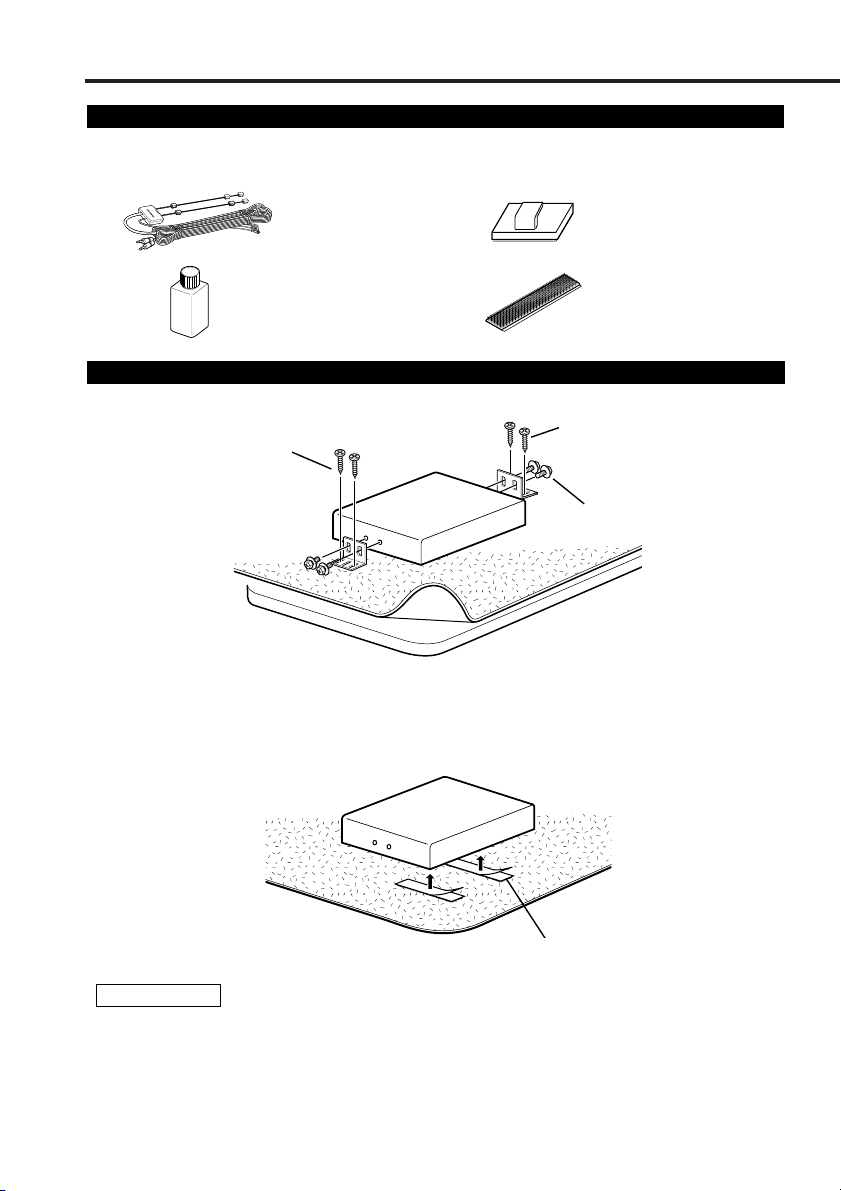
Accessories
External view
......... Number of items
External view
......... Number of items
A
B
........2
........1
C
D
........6
........2
Installation the TV Tuner Unit
■ Securing to audio board
(Provided with the LZ-800W)
■ Securing to pile carpet
Arracher les bandes de protection des bandes velcro, les attacher au bas de l’unité de
dissimulation, et fixer à la moquette.
(Provided with the LZ-800W)
(Provided with the LZ-800W)
(AccessoryD)
2CAUTION
Please do not install the unit near the dashboard, the rear tray, or other important
components. Doing so could lead to injury or accident should the unit come off due to a
shock and strike a person or an important component.
Tapping screws(Provided with the LZ-800W) should be used for mounting. (Attachment with
velcro strips, although easy, can come off with a shock.)
2
Page 3
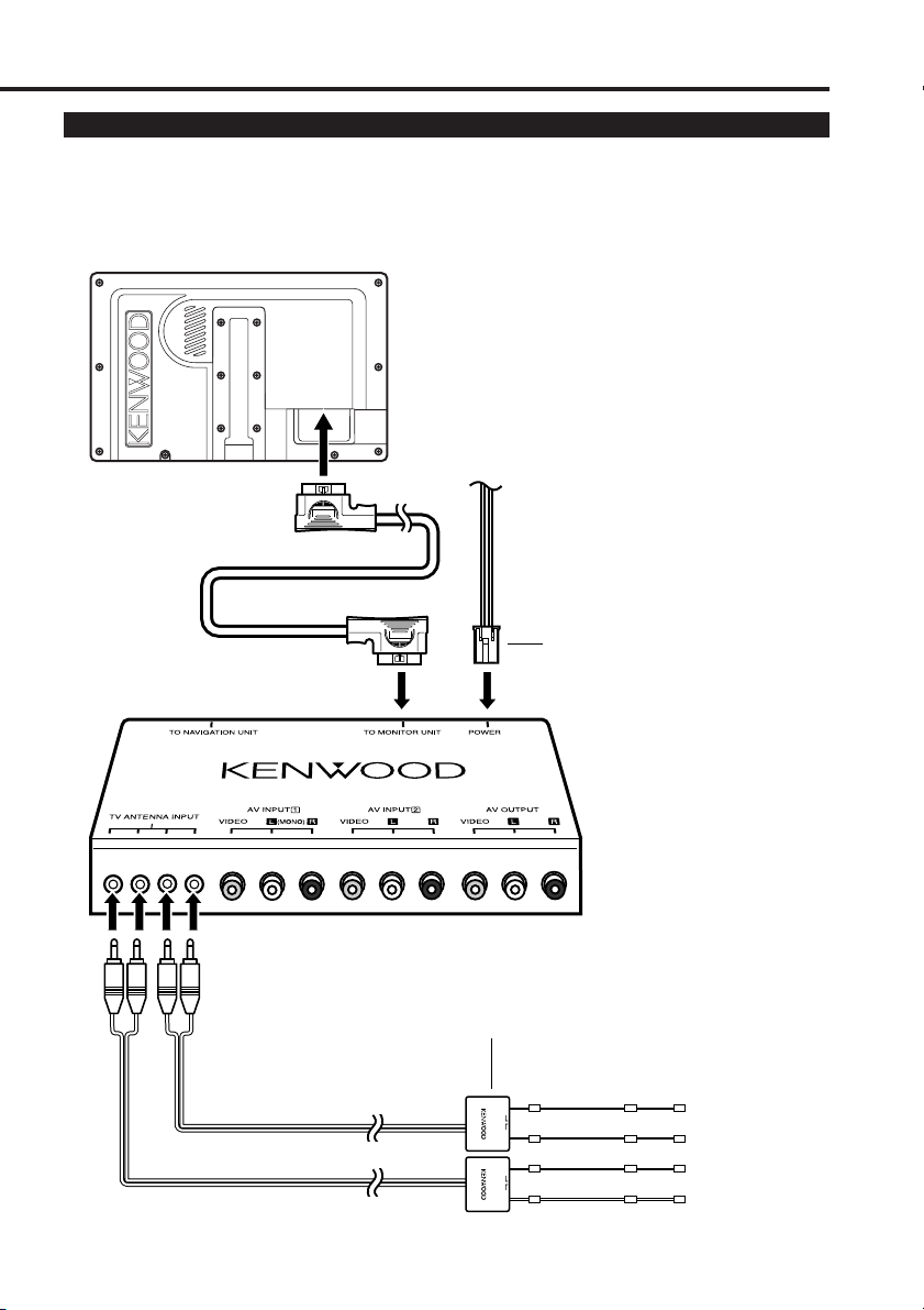
Connecting the TV Tuner Unit
See the LZ-800W instruction manual for details regarding the power harness
and Video Input/Video Output terminals.
Monitor Unit (LZ-800W)
(Provided with the LZ-800W)
(Provided with the LZ-800W)
TV Tuner Unit (KTC-V800N)
TV Antenna Unit (Accessory A)
CAR DIVERSITY ANTENNA
WITH BOOSTER CX-A330
BOOST
ONOFF
CAR DIVERSITY ANTENNA
WITH BOOSTER CX-A330
BOOST
ONOFF
3
Page 4
Installation
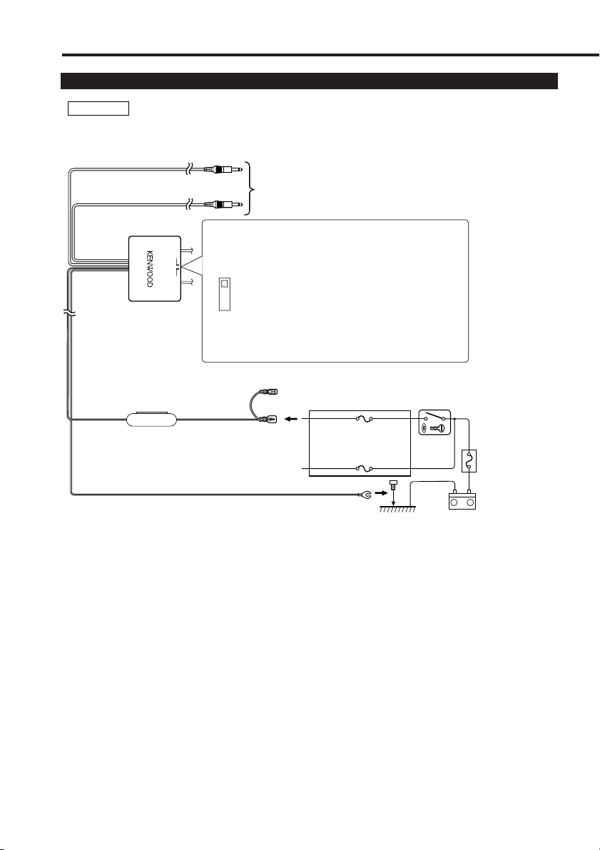
Connecting the Antenna Units
2 CAUTION
Incar antennas have a lower reception sensitivity than antennas intended for outside mounting. The
picture may not appear or may be disturbed if the signal in your area is weak.
To the TV tuner unit
Booster switch
CAR DIVERSITY ANTENNA
WITH BOOSTER CX-A330
BOOST
ONOFF
OFF
• Set this booster switch to "OFF" if there
is ghosting of the on-screen image due to
electromagnetic fields.
•Please set the booster switch to the
"ON" position in case of a weaken field
ON
area.
Ignition cable (Red) ª12V
Fuse(1A)
Ground cable (Black) · (To car chassis)
ACC
Ignition key switch
–
Car fuse box
(Main fuse)
Battery
+
4
Page 5

Installing the Antenna Units
• Attach the antenna to the inner glass surface of the rear window using double-sided tape. Carefully
check the installation location as the tape can only be stuck on once.
• If the surface temperature of the glass of the rear window is low, warm it by turning on the power
of the rear defogger.
A cold window glass surface will weaken the adhesive strength of the double-sided tape.
Also, if installation inside the cabin is performed on a day with high humidity or when it is raining,
the high humidity level will weaken the adhesive strength of the double-sided tape.
• Do not install the antenna in a location where it may obstruct the field of view during driving, such
as on the windshield.
1
Check the location where the antenna is to be
attached.Clean off any grease or dirt from the
installation location using the supplied glass
cleaner
(Accessory B), clean the area with water
and allow to dry.
2 CAUTION
Clean the glass thoroughly as failure to clean the
glass can not only weaken the adhesive
strength of the double-sided tape, but may also
cause it to come loose.
2
Remove the protective strips from the antenna
parts and the back of the antenna unit.
3
Attach the double-sided tape of the antenna
parts and the antenna unit to the rear windshield
glass. Attach the double-sided tape by firmly
pressing down from the top. Secure cables
using the supplied clampers.
4
After attaching the antenna with the doublesided tape, allow it to sit undisturbed for 24
hours. Take care not to apply force to the
antenna or allow it to get wet during this time.
5
Wire the antenna cable to TV tuner unit.
Antenna parts
Antenna unit
Bundle cables with the
clamper bar
(Accessory C)
Rear window
Rear seat
5
Page 6

Specifications
Specifications subject to change without notice.
TV Tuner Section
Color system ................................................................................................NTSC
Television system ..............................................................................................M
Channel converge............................................................2-13ch(VHF)/14-69(UHF)
Channel selection system................................PLL frequency synthesizer system
Demoduration system ............................................................Split carrier system
Antenna input ................................................4-ch diversity (75 Ω /3.5 ø mini jack)
Video input level (RCA jacks)..............................................................1 Vp-p/ 75 Ω
Audio input level (RCA jacks) ................................................................1 V/ 22 KΩ
Video output level (RCA jacks) ..........................................................1 Vp-p/ 75 Ω
Audio output level (RCA jacks)..........................................................500 mV/ 1KΩ
RGB input (13P) ............................................................................0.7 Vp-p/ 75 Ω
General
Operating voltage ..............................................................14.4 V DC (11 to 16 V)
Consumed power (with Monitor unit) ........27 W (25 W: during normal operation)
Operational temperature range ....................................................–10°C to +60°C
Storage temperature range ..........................................................–30°C to +85°C
Size........................................................................188(W) x 30(H) x 144.8(D) mm
Mass ..............................................................................................780 g(1.7 LBS)
TV Antenna
Output impedance ................................................................75 Ω /3.5 ø mini plug
Booster gain (when booste is on) ......................................10 dB(VHF)/ 6 dB(UHF)
Operating voltage ....................................................................................12 V DC
Consumed current ........................................................................................1.0 A
Cable length ....................................................................................................5 m
Size..........................................................................50(W) x 14.5(H) x 500(D) mm
Mass ..........................................................................................70 g(0.1LBS) x 2
7-3/8(W) x 1-3/16(H) x 5-11/16(D) inch
1-15/16(W) x 9/16(H) x 19-11/16(D) inch
6
Page 7

FCC WARNING
This equipment may generate or use radio frequency energy. Changes or
modifications to this equipment may cause harmful interference unless the
modifications are expressly approved in the instruction manual. The user could lose
the authority to operate this equipment if an unauthorized change or modification is
made.
NOTE
This equipment has been tested and found to comply with the limits for a Class B digital device,
pursuant to Part 15 of the FCC Rules. These limits are designed to provide reasonable
protection against harmful interference in a residential installation. This equipment may cause
harmful interference to radio communications, if it is not installed and used in accordance with
the instructions. However, there is no guarantee that interference will not occur in a particular
installation. If this equipment does cause harmful interference to radio or television reception,
which can be determined by turning the equipment off and on, the user is encouraged to try to
correct the interference by one or more of the following measures:
• Reorient or relocate the receiving antenna.
• Increase the separation between the equipment and receiver.
• Connect the equipment into an outlet on a circuit different from that to which the receiver is
connected.
• Consult the dealer or an experienced radio/TV technician for help.
NOTE
This Class B digital apparatus complies with Canadian ICES-003.
Page 8

Installation
C
A
R
D
I
V
E
R
S
I
T
Y
A
N
T
E
N
N
A
W
I
T
H
B
O
O
S
T
E
R
C
X
-
A
3
3
0
O
N
O
F
F
B
O
O
S
T
C
A
R
D
I
V
E
R
S
I
T
Y
A
N
T
E
N
N
A
W
I
T
H
B
O
O
S
T
E
R
C
X
A
3
3
0
O
N
O
F
F
B
O
O
S
T
Accessoires
Vue externe
......... Nombre d’éléments
Vue externe
......... Nombre d’éléments
A
B
........2
........1
C
D
........6
........2
Installation de l’unité Tuner TV
■ Fixation sur le panneau audio
(Fourni avec le LZ-800W)
■ Fixation à la moquette
Arracher les bandes de protection des bandes velcro, les attacher au bas de l’unité de
dissimulation, et fixer à la moquette.
(Fourni avec le LZ-800W)
(Fourni avec le LZ-800W)
(Accessoire D)
2ATTENTION
Prière de ne pas installer près du tableau de bord, de la plage arrière ou d’éléments
importants. Cela pourrait occasionner une blessure ou un accident si l’appareil devait se
détacher à cause d’un choc, et heurter une personne ou un élément important.
Des vis taraudeuses(Fourni avec le LZ-800W) doivent être utilisées pour le montage. (Une
fixation à l’aide d’une bande velcro est facile, mais peut se détacher lors d’un choc.)
8
Page 9

Connexion de l’unité Tuner TV
Voyez le mode d’emploi du LZ-800W pour les détails concernant le harnais et les
bornes de sortie audio/visuelle et entrée audio/visuelle.
L'unité moniteur (LZ-800W)
(Fourni avec le LZ-800W)
L’unité Tuner TV (KTC-V800N/ KTC-V800P)
L'unité antenne TV (Accessoire A)
CAR DIVERSITY ANTENNA
WITH BOOSTER CX-A330
CAR DIVERSITY ANTENNA
WITH BOOSTER CX-A330
(Fourni avec le LZ-800W)
BOOST
ONOFF
BOOST
ONOFF
9
Page 10

Installation
Connexion et installation d'unité antenne TV
2 ATTENTION
Les antennes intérieures de véhicule ont une sensibilité inférieure aux antennes extérieures. L’image
peut ne pas s’afficher ou être déformée si le signal est trop faible dans la zone où l’on se trouve.
Vers l'unité tuner TV
Interrupteur amplification
CAR DIVERSITY ANTENNA
WITH BOOSTER CX-A330
BOOST
ONOFF
OFF
• Placer l’interrupteur amplification sur
"OFF" (arrêt) si des images fantôme dues
à des champs magnétiques apparaissent
à l’écran.
• Placer le commutateur de
ON
l'amplificateur en position "ON" dans
les zones de faible reception.
Câble d’allumage (Rouge) ª12V
Fuse(1A)
Câble de masse (Noir) · (Au châssis de la voiture)
Allumage
Interrupteur d’allumage
Boîte á fusibles
de la voiture
(Fusible
principal)
–
Batterie
+
10
Page 11

Installation d'unité antenne TV
• Fixer l’antenne sur la surface intérieure de la vitre arrière à l’aide de ruban adhésif double faces.
Effectuer cette opération avec précaution car le ruban ne se colle qu’une seule fois.
• Si la température de surface de la vitre arrière est trop basse, l’augmenter en utilisant le dégivrage
arrière.
Une vitre froide empêche le ruban adhésif double faces de coller correctement.
L’humidité a aussi un effet similaire donc, éviter d’effectuer cette opération par temps humide ou
pluvieux.
• Ne pas installer l’antenne dans un endroit ou elle obstrue la vue du conducteur comme sur le parebrise.
1
Vérifier l’état de l’emplacement de l’antenne.
Enlever toute trace de graisse ou souillure à
l’aide du produit de nettoyage de vitre fourni
(Accessoire B) avec l’antenne, nettoyer la zone
avec de l’eau et laisser sécher.
2 ATTENTION
Bien nettoyer la vitre pour éviter de diminuer le
pouvoir adhésif du ruban à doubles faces et
entraîner plus tard son décollement.
2
Retirer les bandes de protection sur les pièces
de l’antenne et au dos de l’unité.
3
Fixer les parties adhésives des pièces d’antenne
et du dos de l’unité contre la vitre arrière.
Appuyer fermement en commençant du haut et
en continuant vers le bas. Fixer les câbles à
l’aide des colliers fournis.
4
Après avoir effectuer le collage de l’antenne
avec le ruban adhésif double face, la laisser
tranquille pendant 24 heures. Ne pas lui faire
subir le moindre effort ou lui faire prendre
l’humidité pendant ce temps là.
5
Faire passer le câble jusqu’à l’unité tuner de la
télévision.
Pièces de l’Antenne
Ensemble antenne
Regrouper les câbles
avec la barre de bridage
(Accessoire C)
Vitre arrière
Siège arrière
11
Page 12

Spécifications
Les spécifications sont sujettes à changements sans notification.
Section tuner de la télévision
Système de couleur......................................................................................NTSC
Système de sélection des canaux ......................Synthétiseur de fréquences PLL
Système de la télévision ....................................................................................M
Convergence des canaux ................................................2-13ch(VHF)/14-69(UHF)
Système de démodulation ........................................Système à porteuse divisée
Entrée d’antenne ............................ Diversité à 4 canaux (75Ω/Minijack de 3,5 ø)
Niveau d’entrée vidéo externe (fiches RCA)........................................1 Vp-p/75 Ω
Niveau d’entrée audio externe max. (fiche RCA) ..................................1 V/22 K Ω
Niveau de sortie vidéo (fiches RCA) ....................................................1 Vp-p/75 Ω
Niveau de sortie audio (fiches RCA) ................................................500 mV/1 K Ω
D’entrée RGB (13 pin) .................................................................... 0,7 Vp-p/75 Ω
Général
Tension de fonctionnement ................................................14.4 V DC (11 to 16 V)
Consommation (avec l'unité moniteur) ..................................................................
Fourchette de température de fonctionnement..............................–10°C à +60°C
Fourchette de température de rangement......................................–30°C à +85°C
Taille ........................................................................188(L) x 30(H) x 144.8(P) mm
Masse ..........................................................................................780 g (1.7 LBS)
Antenne de la télévision
Impédance de sortie ..............................................................75 Ω /3,5 ø miniplug
Gain du booster (lorsque le booster est activé)..................10 dB(VHF)/ 6 dB(UHF)
Tension de fonctionnemen ......................................................................12 V CC
Courant absorbé............................................................................................1,0 A
Longueur du câble ..........................................................................................5 m
Taille..........................................................................50(L) x 14.5(H) x 500(P) mm
Masse ........................................................................................70 g (0,1LBS) x 2
27 W (25 W: pendant le fonctionnement normal)
7-3/8(L) x 9/16(H) x 19-11/16(P) pouces
1-15/16(L) x 9/16(H) x 19-11/16(P) pouces
REMARQUE
Cet appareil numérique de la classe B est conforme à la morme NMB-003 du Canada.
 Loading...