

Page 1

KENWOOD
AUDIO VIDEO SURROUND RECEIVER
KR-V990D
INSTRUCTION MANUAL
KENWOOD CORPORATION
B60-2390-00 (£B) (K. p, c, M, X, Y)
97/12 11 10 987654321 96/12 11 10 987654321
Page 2
tfíntíM
starte
Before aooMng the power
Units are designed for operation as follows.
U.S.A. and Canada.................................................AC 120 Vonly
Australia................................................................. AC 240 V only
F#!ß77BP771F/f^7iI7/7?37
China
......................................................................AC220 V cm
*Other countries
age caretuUy to ensure sate o
..............
AC 110-120/220/230-240 VswitchM
iMtawn.
KR-vggoD [Enj
*AC voltage selection
The AC voltage selector switch on the rear panel is set to the voltage
that prevails in the area to which the unit is shipped. Before
connecting the power cord to your AC outlet, make sure that the
setting position of this switch matches your line voltage. If not, it
must be set to your voltage in accordance with the following direc
tion.
Our warranty does not cover damage caused by excessive line
voltage due to improper setting of the AC voltage selector switch.
WARNING
TO PREVENT FIRE OR ELECTRIC SHOCK, DO NOT EXPOSE THIS APPLIANCE TO RAIN
-----------------------------------------/ Hr
AC voltage selector switch
AC 110- AC 220- AC 11Ü- AC 220y- AC 230-
120V- 240V'^ 120V- i 240V-
Move switch lever to
match your line voltage
with a small screwdriver
ll©©©©
or other pointed tool.
L|©©©©
OR MOISTURE.
CAUTION; TO REDUCE THE RISK OF ELECTRIC SHOCK, DO NOT REMOVE COVER (OR
BACK). NO USER-SERVICEABLE PARTS INSIDE, REFER SERVICING TO QUALIFIED SERVICE
PERSONNEL M
THE LIGHTNING FLASH WITH ARROWHEAD SYMBOL, WITHIN AN EQUILATERAL TRIANGLE, IS INTENDED TO ALERT THE
USER TO THE PRESENCE OF UNINSULATED "DANGEROUS VOLTAGE" WITHIN THE PRODUCTS ENCLOSURE THAT MAY BE
A
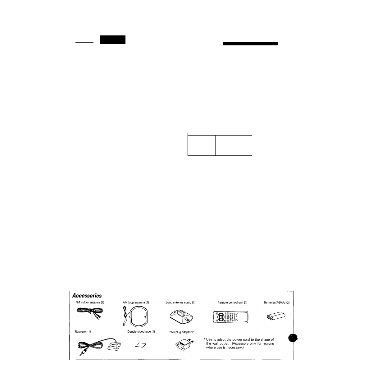
Unpack the unit carefully and make sure that all accessories are put aside so they will not be lost.
Examine the unit for any possibility of shipping damage. If your unit is damaged or fails to operate, notify your dealer immediately. If your
unit was shipped to you directly, notify the shipping company without delay. Only the consignee (the person or company receiving the
unit) can file a claim against the carrier for shipping damage.
We recommend that you retain the original carton and packing materials for use should you transport or ship the unit in the future.
OF SUFFICIENT MAGNITUDE TO CONSTITUTE A RISK OF ELECTRIC SHOCK TO PERSONS.
THE EXCLAMATION POINT WITHIN AN EQUILATERAL TRIANGLE IS INTENDED TO ALERT THE USER TO THE PRESENCE OF
IMPORTANT OPERATING AND MAINTENANCE (SERVICING) INSTRUCTIONS IN THE LITERATURE ACCOMPANYING THE
APPLIANCE.
Page 3
Caution: Read the pages marked A carefully to ensure safe operation. ^
A Before applying the power..
A Safety precautions....................
Special features «
Names and functions of parts m
System connections
How to use the remote control —
Using the OSD (On Screen Display).
Preparing for playback (SET UP).
Unpacking ..............................
..............
..
Connecting the antennas..........................................
FM DE-EMPHASIS/CHANNEL SPACE switch..
Connecting audio components
Connecting video components.................................
Connecting the system control..............................
Connecting the speakers..........................................
Connecting the repeater......................................
Names and functions of keys..
Operations
Switching to GUI {Graphical User Interface) mode .
Operating in GUI mode
System set up........
Surround set up .,
.......
..... .........
.......................
................................
.
:====,===,==1...;^.
.
.................................................
.
^2
,...2
....2
....2
^4
^5 \
^6 ;
....6 ;
....6 ^
... 7
.... 8
.... 9
.. 10
.. 11
!2
,. 12
.. 13
, 14
„14
,. 15
„17 :
..20 i
Normal playback m
Listening to radio broadcasts .
Ambience effects m
Remote controlling video components ...................
Set up code chart —
OSD flow chart
In case of difficulty .
A Specifications mmmmmm
Since this instruction manual explains the operating instructions for models destined for different regions, one part of the
input selector name list and display information vary according to region.
Listening to source components..
Adjusting the sound..
Recording audio.,
Recording video
Tuning radio stations...........................................................
Tuning radio stations by frequency (DIRECT tuning) .
Presetting radio stations......................................................
Receiving preset stations
Receiving preset stations in order (P.CALL)
Sound modes
Playing back with surround sound ..
How to operate video components .
.....................
...................................................
.......................................
.
.....................
.
. 22
.. 22
..23
.25
..25
..26
. 27
.. 27
..28
..29
.. 29
.. 29
. 30
„30
.. 32 ;
. 34 \
„ 34
, 41
, 43
Page 4

Sjjecialhatures
This receiver is provided with a variety of surround modes to bring you maximum enjoyment from your vidj
software. Select a surround mode according to your equipment or the software you are going to play. Enjoy!
. .
The Dolby AC-3 mode lets you enjoy LD software marked
3 format digital signals, in digital surround. By providing up to 5.1 channels of digital audio independently, Dolby
AC-3 lets you to enjoy better sound quality and more powerful presence than conventional Dolby Surround.
imM£Mawm&DOLBY ssimo
This surround system reproduces theater-like surround sound from video software marked .
The DOLBY PRO LOGIC mode uses the built-in directivity enhancer circuit to control the Left, Center, Right and
Surround channel audio signals and reproduce a real sense of sound motion .
The DOLBY 3 STEREO mode uses the directivity enhancer circuit to provide proper acoustic positioning and a real
sense of sound motion even when only the front and center speakers are used.
MRJMBUL.
This mode uses DSP (Digital Signal Processor) to add an element of "presence" to the DOLBY PRO LOGIC signals
(Left, Center, Right and Surround) output from the directivity enhancer circuit, and bring the extra sense of
dimensionality, associated with movie theaters, to your listening room.
EsmsmMmjatWi OBO (Oil Display) - ,
This function uses a monitor TV to simplify the previously difficult setup procedures like, surround setup, remote
control setup code input, and macro-play setup. Once you've completed these setups, all you have to do is eny^
your movies. VP
You can also use OSD for basic operation of source components. Connecting KENWOOD source components wi№
the System Control (SL16 only), lets you use OSD to display information about the current source.
JJBJMtamdBay} remote control
To watch video software, you used to have to use the infrared ray remote control supplied with your monitor TV
and video equipment. This receiver, however, is supplied with a repeater that lets you turn ON and start playback
from your video components once you specify the remote control setup code. Be sure to set up the IR remote before
you start watching movies. *02 *!32
........................
-------------------- ,
, as well as the input of other Dolby AC-
vid^^^
jmmmAY
This function lets you perform a series of operations automatically with the push of a single button.
Once you store the steps necessary to perform a specific operation, like starting playback from your LD player or
video deck, you can perform those operations, like turning ON the power, switching the inputs, and starting
playback, automatically. (To operate video equipment in a macro play, be sure to input the remote control setup code
before starting the macro set up procedure.) -*’02
Page 5
i^tiniiih'tinnMifinHainh.'Mnaihnì:
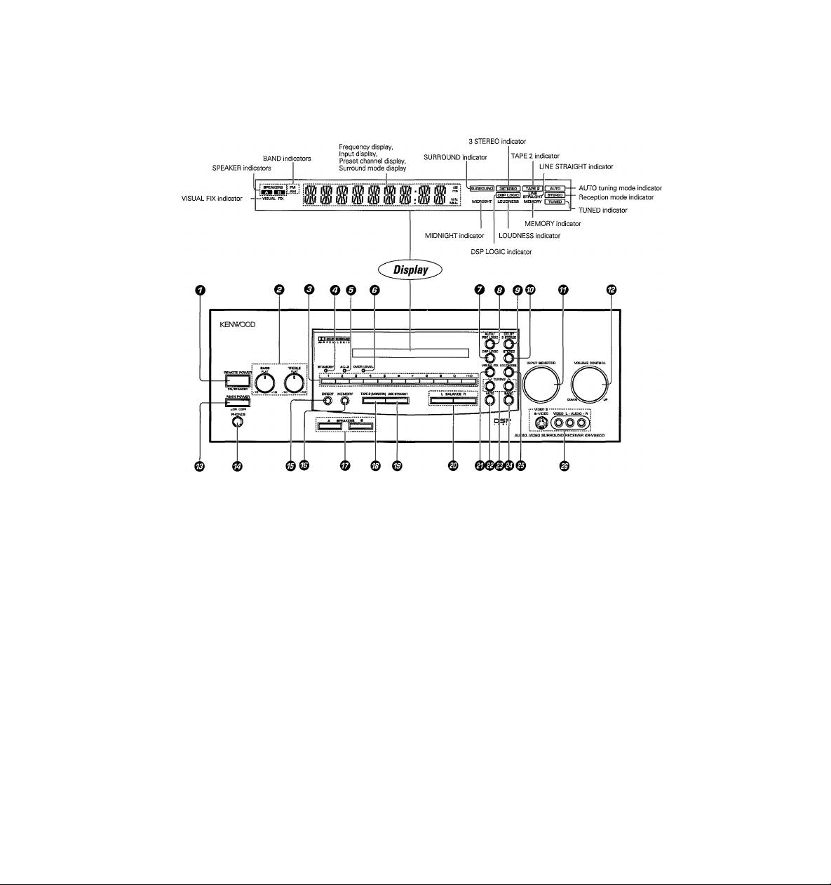
O REMOTE POWER key
Use to switch the power ON/STANDBY
when the MAIN POWER is turned ON.
O Tone Control knobs
O ISIumeric keys
O STANDBY indicator
© AC-3 indicator
Lights when an AC-3 format signal is be
ing played back.
© OVER LEVEL indicator -¡22
Lights when the level of the signal being
input is too high.
O DSP LOGIC key -¡22
Use to turn on, or switch, the DSP LOGIC
mode.
© AUTO/PRO LOGIC key
Use to turn on, or switch, the DOLBY
SURROUND mode.
© DOLBY 3 STEREO key -|22
Use to turn on the DOLBY 3 STEREO
mode.
© STEREO key -23
Use to cancel the surround mode.
© INPUT SELECTOR knob -|23
Use to select the input sources.
© VOLUME CONTROL knob -23
0 MAIN POWER key
Use to turn the POWER ON/OFF.
© PHONES jack -¡^
Use for headphone listening.
© DIRECT key -L^
Use to tune radio stations directly by nu
merical input.
© MEMORY key -¡^
Use to store radio stations in the preset
memory.
© SPEAKERS A/B keys -¡^
Use to turn the speakers ON/OFF.
© TAPE atMONITOR) key -23
Use to monitor a recording.
© LINE STRAIGHT key -23
Use to listen with high quality sound.
m BALANCE keys -23
Use to adjust the volume balance between
left and right.
© VISUAL FIX key -23
Use to lock on to the current video input.
m AUTO key -22
Use to select the auto tuning mode.
© TUNING keys
Use to tune in radio broadcasts.
© BAND key -22
Use to select the broadcast band.
© LOUDNESS key -23
Use to emphasize deep base sounds.
© VIDEO-3 terminals
MOTE POWER switch STANDBY mode
it
'hen the receiver's power cord is plugged in to an AC outlet and the MAIN POWER key is turned ON, the STANDBY indicator will remain
lit, regardless of the ON/STANDBY setting of the REMOTE POWER switch. This Indicates that a small amount of current is being
supplied to the receiver in order to back up the memory contents. This is called the Standby mode. When the standby indicator is lit, the
receiver can be switched ON/STANDBY from the remote control.
Page 6
rnrnrsimmim
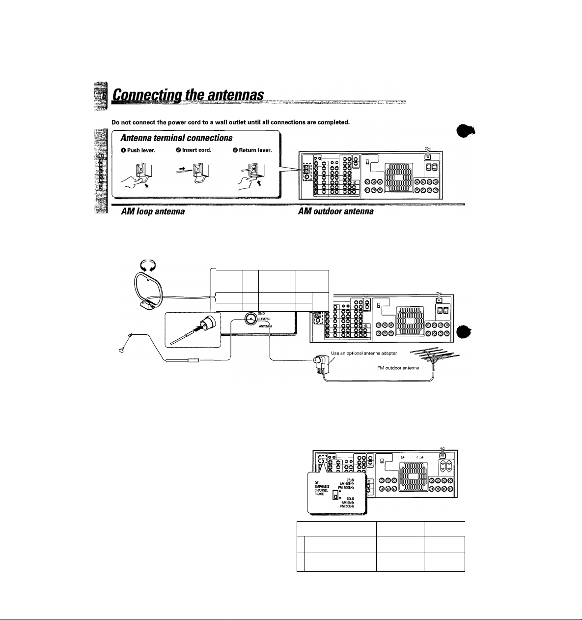
Make connections as shown below.
The supplied loop antenna is for use indoors. Place it as far as
possible from the receiver, TV set, speaker cords and power
cord, and adjust the direction for best reception.
AM loop antenna
r
AM
J
1
FM indoor antenna
If reception is poor with the loop antenna, extend a vinylcoated wire (more than 6 meters long) outdoors, without
disconnecting the loop antenna.
AM outdoor antenna
--------------------
E==:
1®
FM indoor antenna FM outdoor antenna
The supplied indoor antenna is for temporary use only. For
stable signal reception we recommend using an outdoor
antenna. Disconnect the indoor antenna when you connect
one outdoors.
Lead the 75Q coaxial cable connected to the FM outdoor
antenna into the room and connect it to the FM 75fl terminal.
FM DE-EMPHASIS/CHANNEL SPACE switch (Except for U.S./L, Canada and Australia)
The FM DE-EMPHASiS / CHANNEL SPACE switch on the rear panel is
set to the correct setting that prevails in the area to which the unit is
shipped. However, if the FM DE-EMPHASIS / CHANNEL SPACE setting
is not matched to the area where the unit is to be used; for instance,
when you move from area 1 to area 2 or vice versa, desired reception of
AM / FM broadcasts is not expected. In this case, change the FM DE
EMPHASIS / CHANNEL SPACE setting in accordance with the area
corresponding to the table. Thè FM DE-EMPHASIS is switched over at
the same time.
•When changing the setting of the FM DE-EMPHASiS / CHANNEL
SPACE switch, first disconnect the power cord, then reset the channel
space switch, connect the power cord again, and turn the power on.
2 Other countries
Area
U.S.A., Canada, and South
1
American countries
CHANNEL
SPACE freq.
FM; 100 kHz
AM: 10 kHz
FM; 50 kHz
AM: 9 kHz
FM J
DE-EMPHAsfl
75 ps
50 ps
Page 7
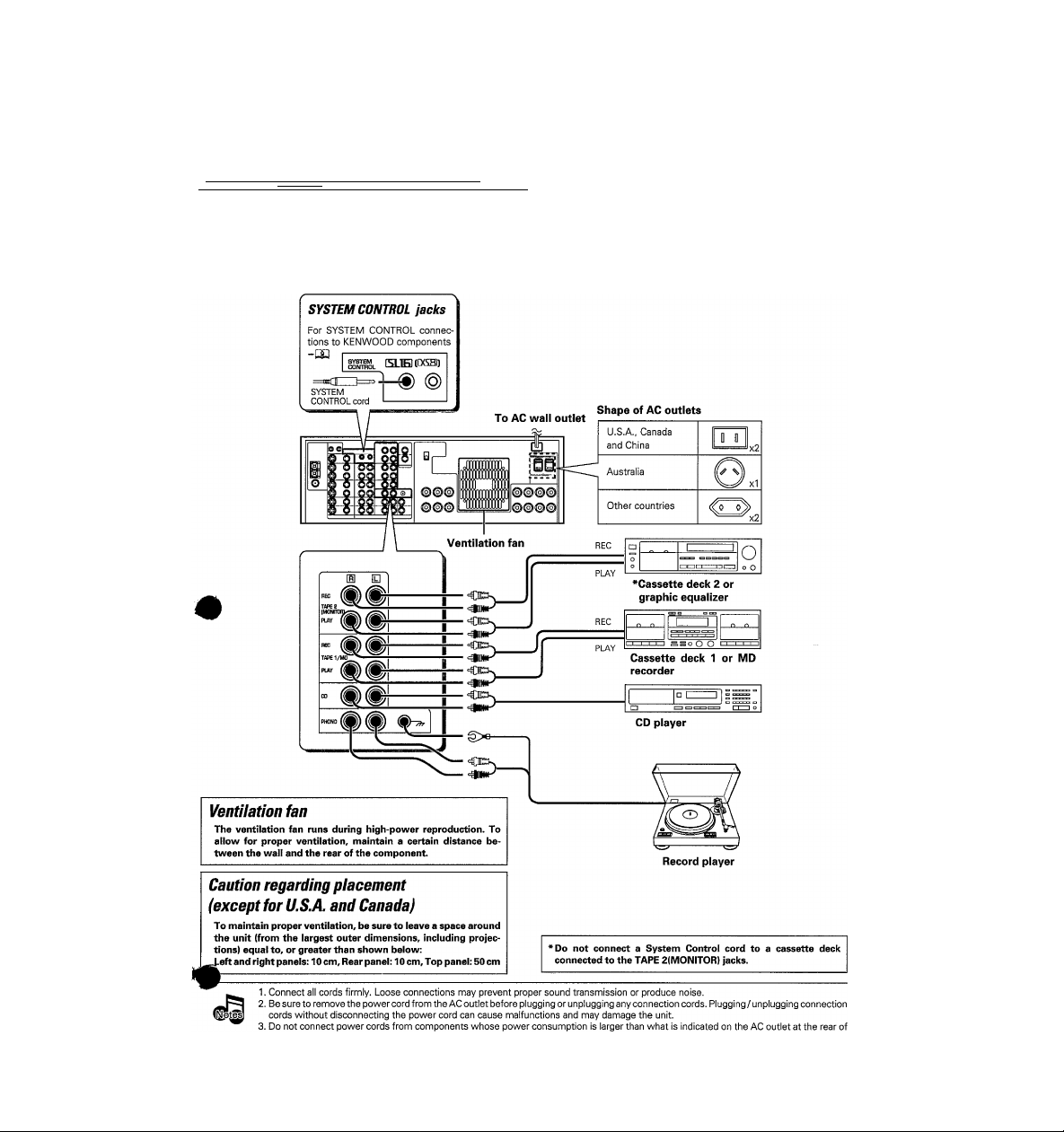
Connecting audio components
mmmmaaBarnmmmnBBaMssmiK .ka::' •
Make connections as shown below.
When connecting the related system components, be sure
.^gMulso refer to the instruction manuals supplied with the
V^ponents you are connecting.
So not connect the power cord to a wall outlet until all
connections are completed.
____
Microcomputer malfunction
If operation is not possible or an erroneous display appears, even
though all connections have been made properly, reset the
microcomputer referring to "In case of difficulty".
Page 8
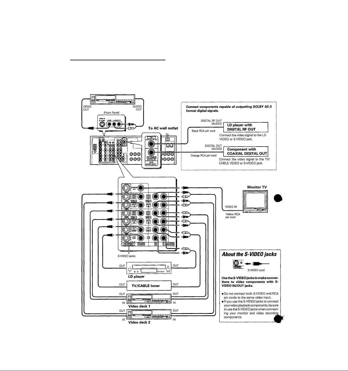
Connecting video components
Make connections as shown below.
When connecting the related system components, be sure to also refer to the instruction manuals supplied with the
components you are connecting.
Do not connect the power cord to a wail outlet until all connections are completed.
Video deck 3 or video camera
Video inputs and outputs
(Yellow RCA pin cords)
Audio inputs and outputs
(Red and white RCA pin cords)
Page 9
Connecting the system control
(~Co\
Connecting system control cords after connecting a KENWOOD audio component system lets you take advantage of
convenient system control operations.
l^cor
lere are two KENWOOD system control modes. Make connections according to the groups of terminal symbols shown
Ш"
'elow.
[XSB] Mode : lets you combine DC2, CXS], and CX?] terminals
[5L1E] Mode : for I5L1E] terminals only
This unit is compatible with both [XS8] and [SL16] modes. It comes from the factory set to the [SL16] mode. To switch to the [XS8] mode, follow
the instructions in "SWITCHING FROM ISL16] TO [XS8]" below.
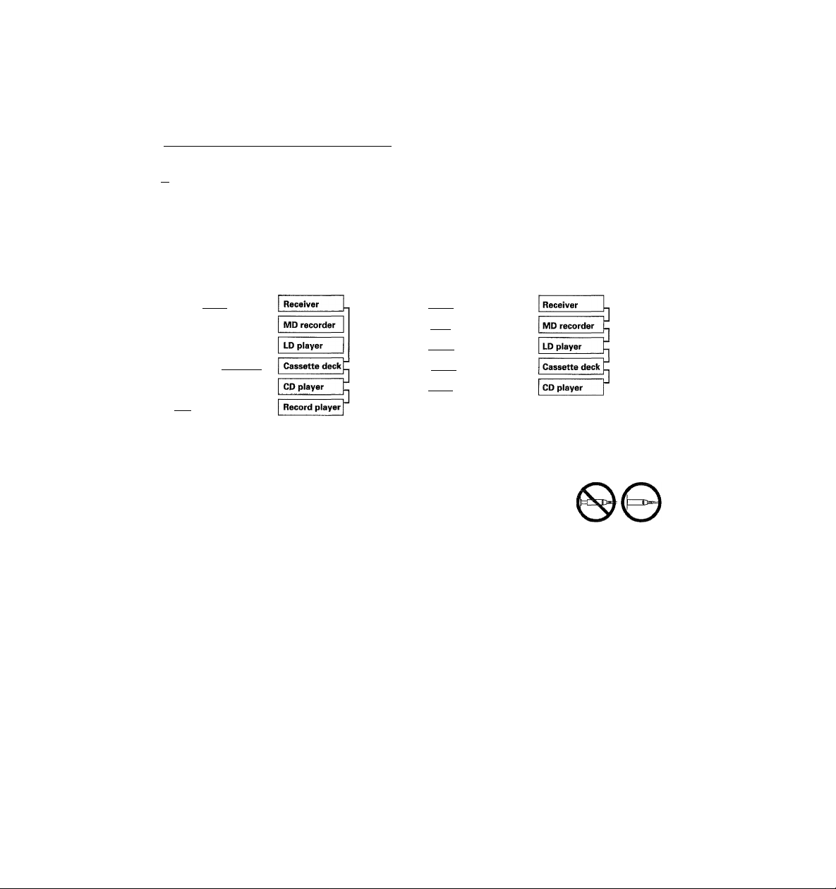
EXAMPLE: [XS8] mode connections
The underlined portion represents the setting of the system control mode.
[SL16] rXS81
[SL16]
[SL16]
rSLieUXSI rXSSHXRl
SYSTEM
CONTROL
cord
[SL16] [Ш [XS8]
[XSl
> Some CD players and cassette decks are not compatible with the ISL16] system control mode. Be sure to use the [XS8] system control mode when
making system connections with equipment that is not [SL16] compatible.
► Some LD players and MD players are not system control compatible. You cannot make system control connections to this kind of equipment.
1. [SL16] equipment cannot be combined with [XR], [XS], and [XS8] equipment for system operations. If your
equipment consists of this kind of combination, please do not connect any system control cords. Even without
system control cords, normal operations can be carried out without affecting performance.
2. Do not connect systenn control cords to any components other than those specified by KENWOOD. It may
cause a malfunction and damage your equipment.
3. Be sure the system control plugs are inserted all the way in to the system control terminals.
EXAMPLE: [SL16] mode connections
The underlined portion represents the setting of the system control mode.
FSLiei [XS81
[SL161
[SL16]
[SL161 [XS] [XS8] [XR]
SYSTEM
CONTROL
cord
rSLISI [XS] [XS8]
[XS]
Record player
SYSTEM CONTROL OPERATIONS
Remote Control
Lets you operate this unit with the system remote supplied with the
receiver.
Automatic Operation (except [XR] equipment)
When you start playback from a source component, the inputselector
on this unit switches to that component automatically.
(Except for TAPE 2.)
Synchronized Recording (except [XR] equipment)
Lets you synchronize recording with the start of playback when
recording from CD, MD, LD, or analog discs.
On-Screen system operation ([SL16] only]
This unit can display the current status of the component you wish to
operate on the screen of a monitor television and let you operate that
component with on-screen operations.
^WITCHING THE TAPE 11NPUT TO MD ([SL16] only)
^^f you set the SYSTEM CONTROLto [SLI 6] modeand connectan MD ^
recorder, be sure to switch the receiver's TAPE 1 input to MD.
To switch the input, follow the steps shown below. (The input can
also be switched through an on-screen operation.)
SWITCHING FR0M[SL16] TOPCSS] -w
You can easily change the system control mode with the following
operation. Do this operation after completing all connections.
Switching to [XS8] : Hold down the BAND key and switch the
Switching backtoISLI 6): Hold down the AUTO key and switch the
•This operation will not affect items stored in the memory.
You can also change the mode using the On Screen Display.
>iDI like to make the unit completely (and permanently) [XL8]
0 Set the input to TAPE 1
0 Hold down the AUTO key on the receiver for more than 2 seconds.
Repeat to return to the original input setting (TAPE 1).
MAIN POWER key from OFF to ON.
MAIN POWER key from OFF to ON.
The system control mode will revert to [SLI6] if the unit
is not turned on for three consecutive days. If you would
compatible, please consult your dealer.
Page 10
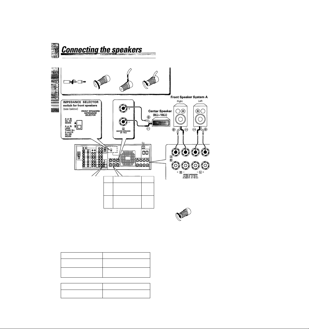
O Strip coating.
O Loosen.
© Insert.
O Secure.
• Never short circuit the + and - speaker cords.
• If the left and right speakers are connected inversely on
speaker cords are connected with reversed polarityf
sound will be unnatural with annbiguous acoustic imagl
Be sure to connect the speakers correctly.
• To emphasize deep bass sounds, connect a sub-woofer as
desired.
Use the FRONT SPEAKERS SYSTEM B terminals if you want
to connect a second front speaker system.
%
Powered
sub-woofer
i
[HIspuI^fis [D
(8-1 BO)
©
Rear Speakers
(8£2~16i2)
(Be sure to connect both rear speakers)
Ì
oU
Setting the FRONT SPEAKERS IMPEDANCE SELECTOR
When using FRONT SPEAKERS A and B separately.
Speaker impedance
40,60
80, 160
When using FRONT SPEAKERS A and B at the same time
Speaker impedance
80, 160
Selector position
B4
Bt
Selector position
Connection of banana plugs (ForU.S.A. and Caaada only)
O Secure. © Insert.
Left
• Sound will not be heard if the
speaker terminal is not fully
secured.
CAUTION: TO PREVENT FIRE, OR DAMAGE TO THE RECEIVER,
Set the IMPEDANCE SELECTOR on the rear panel of the receiver
according to the impedance of the speakers you plan to use.
•When the IMPEDANCE SELECTOR switch is set to “A op B :LESS
THAN 8D, A and B : 8Q OR MORE”, it is possible to use the A a^
B speakers at the same time.
Therefore, when using the speakers A and B simultaneously, be
to set the IMPEDANCE SELECTOR switch to the A or B :LESS THi
80, A and B : 80 OR MORE" position.
• Set the MAIN POWER key to the OFF position when connecting
speakers or adjusting the IMPEDANCE SELECTOR.
SET THE IMPEDANCE SELECTOR SWITCH AS DE
SCRIBED BELOW.
\ anu
#
■\m
Page 11
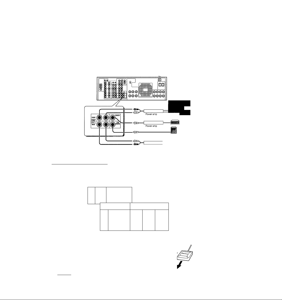
PRE OUT connections
these jacks if you want to listen at even greater volumes or enjoy a different sound quality.
^^»necting a speaker cord directly to a PRE OUT jack will not produce any sound from the speaker. Connect the PRE OUT jacks to powered speakers
^^power amplifiers connected to speakers.
Be sure to set one of the SPEAKERS keys (either A or B) to the ON position when using the PRE OUT jacks.
il
___
Front Speakers
Center Speaker
Powered
Sub-woofer
m
Power amp
^nnectina the repeater
Setting up the repeater lets you control your video components with the receiver's remote control. This repeater sends out signals corresponding to those
of the remote supplied with your video equipment. There are 2 repeaterjacks on the rear panel. One is for the supplied repeater. Depending on the repeater
and the locations of your video components, it may not be possible to control all your video components with just one repeater. If you would like to use
2 repeaters, please consult your dealer.
f'
<
i
3--' ^oo
1 Ql
1
Q QQ
i
1 O OO OO
|o
1
o oo ool
1
Q OO OO
Placement
This repeater outputs infrared ray remote control codes in three
^^in
lirections (shown at right). Use the supplied double-sided tape to
¡cure the repeater in a position where it can operate your video
;omponents. The range of operation depends on the shape and size
of your room. Place the repeater so that there are no obstacles
between the repeater and the remote receptors on your video
components. Obstacles may prevent remote operation of your video
components.
________________________________________________
O O
=CZI>—
—
QQ
Ql
yj
(QnQ tzzz?
©00
©0©
0
Repeater (supplied)
'—
QO
©000
©00©
Remote control code output directions
Page 12
This remote control has 3 operating modes; the function of each key changes accordingly.
Graphical User Interface (GUI) mode
KENWOOD mode.........................................This mode lets you operate the receiver, and other KENWOOD source components,
Video mode
Certain operation keys have different functions in different operation modes. Be sure to set the remote to the correct mode
before operation. This section explains basic operating procedures and the KENWOOD operation mode.
............................................. Lets you operate both KENWOOD and other video components. (The appropr(^^
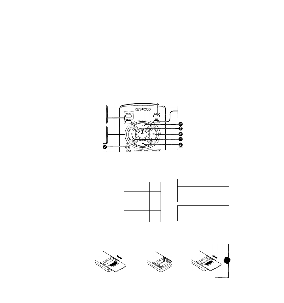
Names and functions ofkevs
Numbered keys have differentfunctions in different modes. For details, seethe "Remote control key operation table".-«
MACRO 1, MACRO 2 keys
Use to operate several components
automatically (MACRO PLAY).
In Graphical User Interface (GUI) mode,
use to move the pointer. -¡22
In other modes, use to operate the various
components.
........
Lets you operate the receiver (and related components) by moving a hand that
appears on the screen of your monitor TV.
like cassette decks and CD players, using this remote control. (The component you
want to operate must be connected with a SYSTEM CONTROL cord.-[2^ _
setup codes must be entered beforehand.-*pS)
To use the GUI mode -pi)
To operate non-KENWOOD components
/
------------------
O
GUI key
Use to activate the Graphical User in
terface mode. -122
KR-vggoD [En]
INPUT key
Use to select an input source. -(22
DISPLAY MODE key
Use to switch the display mode.
TAPE 2(M0NIT0R) key
Use to monitor a recording.
MUTE key
Use to temporarily mute the sound.
Loading the batteries
O Remove the cover.
Model: RC-R0903
infrared Ray System
IZZ3 iz=3 nZD.r
i CP ‘-‘Cd-r--w-:
lMÌ5N№fel ; ■ VIDEO 2 CABLE/SAT. ;
t] Ö SliiS
© ©
a
iSilQi
IVI
~r
REMOTE CONTROL
23
MUTE
iv!
T
.J
Component control selection keys |
Activate the Kenwood operation mode,
and select the component to be re^
mote controlled.
Component control selection keys
Activate the Video operation mode,
and select the component to be remote controlled.
Numeric keys / +10 key
VOLUME key
Use to adjust the volume.
O ENTER key
Use when entering TV channels.
J
® Insert the batteries.
• Insert two AA-size (R6 / SUM-3) batteries as indicated by the polarity markings.
© Close the cover.
-ß2
Page 13
Onerations
Turn on the receiver.
Set the input selector to the component you
I
want to control.
I Use a component control selection key to
select the component you want to control.
I Refer to the "Remote control key operation
table" and press the key corresponding to the
operation you desire.
•When pressing keys in succession, press each key firmiy and be sure to wait at least 1 second before pressing the next key.
Remote control key operation table
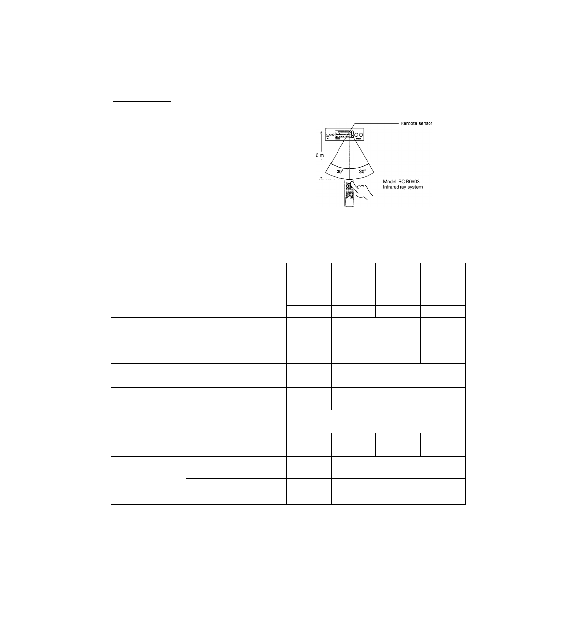
Operating distance
'''^..Connponent control
^"^.^election keys
Key names
O POWER key (
■p II key
© ►/!! key
---------
O key ^ ^
© key
o-key <d>
© REC key (g)
© ANY key (A)
ANY key (V) \/
REC
1. The supplied batteries may have shorter lives than ordinary batteries due to use during operation checks.
2. Replace both batteries with new ones when you notice a shortening of the distance from which the remote control will operate.
3. Placing the remote sensor in direct sunlight, or in direct light from a high frequency fluorescent lamp may cause a malfunction.
In such a case, change the location of the system installation to prevent malfunction.
POWER
REMOTE POWER key
)
BAND key »gQ
P.CALL (A) key
{When the input is set to TUNER)
P.CALL (V) key
{When the input is set to TUNER)
AUTO key
{When the input is set to TUNER)
TUNING (A) key
(When the input is set to TUNER)
TUNING (V) key
(When the input is set to TUNER)
RECEIVER
CZI
TAPE A
1 1
TA^D
1
_____
1 TAPES)
II (Pause)
► (Play)
►► (Fast
forward)
◄◄ (Rewind)
• (Record) Disc Skip
► (Play)
◄ (Play)
CD
CZl
(Systenn Control
►/H
(Play/Pause)
■ (Stop)
►► (Search)
UD
(ZZI
operation)
»i (Skip)
(Skip)
(Search)
TAPE B/MD
CZI
{For MD)
II (Pause)
► (Play)
• (Record)
Page 14

This receiver incorporates an on screen display (OSD) feature to provide information in large easy to read characters and to
simplify operation. OSD lets you carry out three types of operations using the remote control's GUI (graphical user interface)
mode. But first, lets see what kind of screen OSD provides.
KR-V390D (En]
Turn on the components you want to use.
• Set the MAIN POWER key to the ON position.
• Set the REMOTE POWER key to the ON
position.
•Turn on the connected monitor TV.
Activate the GUI mode.
%
This is the first display that appears when you activate the GUI mode.
MAIN MENU
CD
PHONO
TUNER
TAPE1
iOVIDEOI
1VIDE02
JVIDE03
ITVDCABLE
JLD
□TAPE2M0NIT0R
fe-
I u ? I
-----------
Here's what you can do in GUI mode
O Create an ideal AV environment (Set Up).
You can set up your AV system for efficient operation of all the audio and video equipment connected to this receiver. Set
according to your equipment. (SYSTEM SET UP)
This mode also lets you complete the required surround setup. Once surround setup is complete, you may not need to adjust
it again unless you change (or add) speakers. (SURROUND SET UP)
It may seem tedious but after you complete these set up operations, you will have a fully integrated AV system.
O Select surround modes on-screen.
The receiver lets you choose from various home theater operations while looking at the screen of your monitor TV. So you
can stay seated for simple operations.
0 Switch input source and operate other components.
The GUI mode also lets use the monitor TV screen for basic operations of components connected to the receiver with
SYSTEM CONTROL cords. With the [SL16] mode, the current status of the source component is displayed in red.
You can also conduct basic operations of video components by entering the remote control set up code. In this case, the
current status of the video component is not displayed.
Since the icons shown on the monitor TV are similar to the symbols on the operation keys of each source component, also
check the operating instructions supplied with the source components during operation.
O Switch input sources and operate other components.
The current input is displayed in blue. When you select
another source, the input switches and the operation screen
for that component is displayed (except for VIDEO 3 and
PHONO).
- VIDEO input display
Red: Represents the current video input.
Blue: Shows that the video input is locked (VISUAL FIX).
Pointer ^1^
r
Move this hand (pointer) to conduct on-screen operatior^^
O
Create an ideal AVenvironment.
O Select surround modes on-screen.
'VISUAL FIX"-^
5
Page 15

CD (ZZI (ZZI (ZZI
S (±3i±: (±D
SSaS
Keys or controls used in this operation.
Operating in GUI mode
On-screen operation in GUI mode consists of moving the hand shaped pointer icon to select items from the screen.
First of all, lets try moving the pointer freely and selecting an item.
Activate the GUI mode.
•The remote control switches to the on-screen operation mode.
• If no menus are displayed on screen, GUI mode is activated.
If a menu is displayed, GUI mode is cancelled.
MAIN MENU screen
MAIN MENU
]CD
mVIDEOI
ffiVIDE02
.PHONO
ffiVIDEOS
Ituner
ffiiVnCABLE
1TAPE1
ELD
□TAPE2M0NIT0R
ii
IM GS
KR-Va9QD [En]
Move the pointer.
Press the item you desire.
0
Place the finger on the item you want to press.
EXAMPLE; Selecting the sound menu.
O Press.
EXAMPLE: moving the pointer downwards toward the right.
• You can move the pointer in up to 8 different directions by pressing
different key combinations. Try moving the pointer around the screen
in different directions.
•To select an item, press the (►/ii) key located in the center of the
remote control after moving the finger of the pointer on top of the item
you want to select.
The SOUND MENU screen appears.
SOUND MENU
CD CS EEl
(LSI H is]
IstmIghtI
rsTÈRÈoT
rwi ns~i 1 LQGffi 1
fM^ Ml
m
Page 16

Convenient items for on-screen operation
Convenient and often used items are displayed at the bottom of the screen for you to use as necessary. If an item cannot be used with a certain menu,
it will not be displayed.
Displays the next menu.
Displays the SOUND MENU.
Ib^Ì?uI IbACkI In'ÉtI
Returns to the MAIN MENU.
Displays the previous menu, recei^ Displays the SET UP menu. *122
Activates the MIDNIGHT mode for
Dolby AC-3 surround.-^C^
+ A+ SET
^ UiL
Adjusts the dimmer
(3 levels).
Screen menu structure
Below is a general outline of the screen menu structure. Choose the menus according to the screens you wish to access.
Refer to the circled numbers shown below and see the "OSD flow chart" for information about the contents of each screen.
Main menu *¡22
Switch inputs • Operate source components *¡22
— TUNER ®
Sound menu *|^
— MD®
SURROUND SET UP
► SPEAKER SELCTION & DISTANCE (D
SPEAKER LEVEL®
INPUT LEVEL®
lYSTEM^ET up
SYSTEM CONTROL (j
REMOTE CONTROL®
TAPE1 ®
VIDE01 ®
VIDE02 ®
TV®
CABLE ®
LD®
LO SET UP d
Page 17

Use the SET UP menu to create an ideal AV operating
environment by matching the system control functions to
your components. The SET UP menu arranges for proper
control of other KENWOOD components and systems, as
well as video equipment from other manufacturers.
I^eparations
Sj^msetug^
Choose the SYSTEM SET UP menu.
\ Set the SYSTEM CONTROL.
Set the KENWOOD system control. For details regarding SYSTEM CONTROL, i
•Turn on your monitor TV.
O Choose a SYSTEM CONTROL mode.
This switches the KENWOOD SYSTEM CONTROL mode. For details regarding
SYSTEM CONTROL, see "Connecting the system control".
• If you switched the SYSTEM CONTROL mode in "System connections", check to make sure
the mode is correct and go to the next step.
• If the POWER is not turned on for 3 days, the SYSTEM CONTROL mode will automatically
return to [SL16i. To set the receiver to [SL16] permanently, consult with your dealer.
SYSTEM CONTROL
............UP............
OR REMOTE DSYNCHRO
■...
............
¿WW-lfup’r
TOnI iSl
................................................................................................................................................................
I0i
...
.. J-
T
O Choose how to operate your LD player.
When you use a SYSTEM CONTROL cord to connect a KENWOOD LD player
compatible with the [SL16] system control mode, choose the SYSTEM CONTROL
and iR remote operations.
O Choose either TAPE 1 orMD ([SL16] only}.
This determines which component can be operated by the SYSTEM CONTROL.
The input you select can then be chosen with the input selector.
•When the SYSTEM CONTROL is set to [SL16], and a [SL16] mode compatible KENWOOD MD
recorder is connected to the TAPE1/MD jacks, select "MD".
CZ) CZI CZI IZZ)
' C±)C±1 £±D
Keys or controls used in this operation.
i "Connecting the system control",
O Continue to next screen.
continued on next page
Page 18

Setting up the IR REMOTE CONTROL
Before operating video components using remote control supplied with this receiver, you need to input the setup code that
corresponds to the IR remote control of the component you want to control.
O Look up the setup code for the component you want to control.
Use the "Setup Code Chart" to look up the setup code after determining the maker
and the remote control capabilities of the component you wish to control.
EXAMPLE: To enter the setup code for a KENWQQP VCR ^ Q53. Q5g..an.d-Qa2.
If there is more than one setup code, input each code to see which one turns the
power on. That will be the correct code for your component.
IR REMOTE CONTROL
©
ILD
iViDEOI
IcABLE
iVlDE02
©"053‘: T
0 Select the input corresponding to the component you want to control.
SeJectA/iQEQJlj^iVinm^
O Enter the setup code (3 numbers).
Use the remcte cgntrol's numeric keys to enter
O Select SET. ^
O' pSEjJ fl j
..........
"lip”"'
0 Select POWER and check to see that the component you want to control
turns on.
If the component does not turn on, and there is more than one setup code, enter
another setup code and try again.
• If you choose POWER when setting the mode for the current monitor TV, the monitor TV will
turn off and you will not be able to see the screen. In this case, press the enter (►/ii) key on
the remote control again, The monitor TV turns on, and the set up screen is displayed.
0 Repeat steps 0^0 to enter setup codes for all the components you want
to control, then continue to the next screen.
Although each setup code is designed to work with a number of different models,
certain codes may not work with some models. (Also, certain codes may only operate
some of the functions available on a given model.)
MACRO SET UP.
This section shows you how to set the receiver to control several components in succession (MACRO PLAY). After completing
this setup, you can perform a series of operations automatically, simply by pressing the MACR01 or MACR02 key. Enter the
setup codes for the video components you want to control beforehand.
O Determine the order of the operations you want set as a MACRO PLAY.
EXAMPLE : Turn the receiver's power ON Set the INPUT on the receiver to
For this example .we'll store these operations as'MACROI.
VIDE01 "4 Set the sound mode to DOLBY PRO LOGIC Turn the
monitor TV ON ^ Switch the input on the monitor TV Turn the
VCR ON ^ start playback from the VCR.
0 Select the macro number you want to set
Select .1
continued on next page
the
*
ge I
Page 19

MAnPn -QPT IID _
"iNPUf "■ MEÒT'Q-O^
"iv
..............
VIDE01
TV INPUT n ^
■"sound"’"
"vtùtfOi 'u
MACRO SET UP
INPUT nuinpru
uiiii-in pnwiRt I ^
■ ■ W ■input ■ ■"’□■pUNC.T©- (2)f
"bOUNU ’u«"'
VIDE01 □
MACRO SET UP
INPUT DViDEOI
....JV..................................................-7-^
:--"VlDE01 POWERlJSs
‘"Tv" INVui.uhUPiO'. Y ‘
-VIDE01
....................................ТЖаУ"‘^'®_5(2)Ж
OTliiu"“
POWEbQ
....
..
........
™
:ÀNCEL
□SET „ nCANCEL
MACRO HI El
□SET ^ DCANCEL
MACRO Oil
I^mai’n Шк1
KR-V93DD [En]
0 Enter the commands for the receiver.
d)Set the receiver's input selector to the source you want to play. This setting also
turns on the receiver (when the MAIN POWER key set to the ON position.)
The INPUT changes as follows:
none — CD “► TAPE! A (deck A) or WID TAPE1B (deck B) or MD — LD
VIDE01 VIDE02 -► TV -► CABLE -► none
SelegtViPEQT
• If you connect a single cassette deck, select "TAPE1B" when selecting the TAPE 1 input.
•To playback from audio components, make system control connections to KENWOOD audio
components beforehand.
©Select the SOUND mode by referring to "Sound modes". -*l2il
The mode changes as follows:
STEREO PRO LOGIC -► AUTO — DOLBY 3 STEREO — DSP LOGIC
^ STEREO
Select PRO LQjaiil
O Enter the commands for your monitor TV.
0Set the timing for the monitor TV commands. Your monitor TV may not be able to
receive remote commands immediately after the POWER ON signal. This setting
lets you turn ON the monitor TV and program a delay before the next signal.
The timing changes as follows:
none (no POWER ON signal; sends remote command immediately)
-►Is (sends command 1 second after POWER ON) 5s (5 seconds after)
-► 10s (10 seconds after) -► none
Select 5s.
© Set the command necessary to switch your monitor TV input in order to view video
playback. First, determine how many times you have to press the input selector on
your monitor TV to reach the correct video input, then set that number (FUNC.1,2).
If you watch videos by choosing a TV channel instead of switching the input, set the
correct channel (TV1CH, TV2CH, TV3CH).
The setting changes as follows:
none (0 times) -► FUNC.1 (1 time) -► FUNC.2 (2 times) -► TV1CH -► TV2CH
-► TV3CH none
• If your TV switches to VIDEO when you press the input selector once:
■4 Select FUNC.1
O Enter the commands for your playback source (VCR).
© Set the timing for the command of the video components, such as a VCR. It is also
necessary to program a delay between the POWER ON and PLAY signals for your
playback source.
The timing changes as follows:
none (no POWER ON signal; sends remote command immediately)
-►Is (sends command 1 second after POWER ON) -► 5s (5 seconds after)
-► 10s (10 seconds after) -► none
Select 5s.
© Set the operation mode for the playback source. If the playback source is a TV (etc.),
use the remote's numeric (and ENTER) keys to select the channel.
Select PLAY.
O Select SET.
This completes the setup for MACR01.
O To enter another MACRO SET UP, repeat steps 0-4^.
O Go back to the main menu.
O Press the GUI key on the remote to turn off the on-screen display.
To use the MACRO PLAY
ЪЪ
t
This compietes the system setup. If you add a new component or change a component, be sure to return to SYSTEM SET UP
and correct the settings that apply to the component that was added or changed.
o Load the video (or audio) software.
• Remove video (or audio) software from all other connected components.
O Press MACR01 or MACROS when the receiver's MAIN POWER switch is set
to ON to carry out the operations set in the respective macro.
• If you set the macro to turn ON the power to your video components in steps OTl) and
©-d), be sure those components are turned OFF when you press the MACRO key. If they
are turned ON when you press the MACRO key, they will be turned OFF.
Page 20

Keys or controls used in this operation.
Surround set UP
To obtain the most possible enjoyment from the receiver's various surround modes, be sure to complete the surround set up
as shown below.
Speaker placement
Front speakers ;P!ace to the front left and right of the listening position. Front
Center speaker: Place front and center. This speaker stabilizes the sound image
Rear speakers : Place to the direct left and right, or slightly behind, the listening
Sub-woofer : Reproduces powerful deep bass sounds.
• Although the ideal surround system consists of all the speakers listed above, if you don't
have a center speaker or a sub-woofer, you can divide those signals between the availabl
speakers in the following steps to obtain the best possible surround reproduction from
speakers you have available.
Go to the SURROUND SET UP screen.
I Select the speakers and enter the speaker distance.
O Select the speakers you connected to the receiver.
When you select the icons for the speakers you connected, they turn grey,
L,R Front speakers (left and right): Are already selected.
C Center speaker : Switches each time the icon is presse«
LS, RS Rear speakers (left and right) : LS and RS are selected at the same time,
SW Sub-woofer
speakers are required for all surround modes.
and helps recreate sound motion. Be sure to connect a center
speaker when using the Dolby 3 Stereo mode.
position at even heights, approximately 1 meter above the ears
of the listeners. These speakers recreate sound motion and
atmosphere. Required for surround playback.
SMALL ^ select when using a relatively small center speaker.
LARGE -► select when using a relatively large center speaker.
continued on next page
Dn t
>bj^
3
Tie. I
1
ge I
Page 21

Whafs delay time?
The sound you hear is composed of sound that comes to your ears
directly from the sound source (direct sound), and sound that is
reflected off the walls, floor, and ceiling of your room (reflected
sound). Reflected sounds arrive at your ears slightly later than the
direct sounds. Delay time is the difference in arrival time between the
direct sound and the reflected sound.
This receiver sets the appropriate delay time automatically when you
input the speaker distance.
0 Enter the speaker distance.
(A) is the distance from the listening
position to the front speakers.
(B) is the distance from the listening
position to the rear speakers.
To enter the distance:
® Choose aJ (or B J)
CD Use <3 and o to enter the appro
priate distance (from Om(Oft) to
9m{30ft}).
•The delay time is calculated automatically
when you input the speaker distance.
•The Dolby AC~3 mode and the Dolby Pro
Logic mode have different delay times.
O Continue to the next screen.
Qj Adjust the volume levels of each speaker.
A test tone is emitted from the speaker displayed in red. Listen to the test tone and adjust the volume level of each speaker so
that they produce the test tone at the same volume level as the front speakers.
O Select the test tone type.
AUTO : The test tone is switches between each speaker in regular intervals.
MANUAL ; The test tone only comes from the speakeryou select (displayed in red).
OFF : Stops the test tone.
O Adjust the Volume level of each speaker.
TESLTQNE nPE ; , .
MnOFF" DAUTQ DMANUAL; -
(DUse the ◄ and ► icons to adjust the balance between the front (left and right)
speakers.
(D Listen to the test tone and select the speaker you want to adjust.
•The name of the selected channel (on the right side of the screen) turns red, to show that it can
be adjusted,
(D Listen to the test tone and adjust the volume level of the speaker.
<1 : Lowers the volume > : Raises the volume
•Adjust the sub-woofer as you desire.
© Continue to the next screen.
I Adjust the audio input level of the connected components.
The OVER LEVEL indicator lights during playback the signal being input from an analog source is too large. If this occurs, use this
screen to attenuate the input level for that source.
INPUT LEVEL
o
iDTAPE2>M0N!T0R
O Select the input.
© Select an input level.
The input level is adjustable in 3 levels. Choose the smallest level required to extinguish the
OVER LEVEL indicator (normally, set to 0 dB).
0 dB ^ -3 dB ^ -6 dB
© Return to the main menu.
O Press the GUI key on the remote to turn off the on-screen display.
....
t
This completes the surround setup. If you add a new component or change a component, be sure to return to SYSTEM SET UP
and correct the settings that apply to the component that was added or changed.
.
Page 22

Pt6D3r3tionS •Turn on the power to the related compo-
~ nents.
• Set the MAIN POWER key to the ON posi
tion.
MAIN POWER
^3^
Listening to a source component
Turn on the receiver.
Seiect the source you desire.
Adjust the volume.
Decrease volume Increase volume
O
VOLUME CONTTIDL
A ON : Sound from the speakers connected to the SPEAK
A+B ON ; Sound from both the speakers connected to the
A+B OFF : No sound from the speakers. Use this setting when
•When both SPEAKERS A and B are ON, activating a surround mode
The VISUAL FIX function lets you lock on to the current video
from VIDE01 to VIDEO 2, you can watch the images from VIDEO
•The on-screen display (MAIN MENU) also lets you select, or check,
• If TAPE 2CMONITOR) is ON, you will not hear the selected input
ERS A terminals on the rear panel.
B ON : Sound from the speakers connected to the SPEAK
ERS B terminais on the rear panel.
SPEAKERS A and B terminals on the rear panel.
listening with headphones for stereo sound in all
playback modes.
turns SPEAKERS B OFF automatically. In this case, to listen with
SPEAKERS B, press the SPEAKERS B key; SPEAKERS A turn OFF
automatically.
The input sources change as follows:
[-► ® TUNER (Frequency display)
(2) TRPE I (ND)
(D ('lUEO I
® i'lJIEOR
(Dl'IJJEOB
(D Ttf'/CRULE
® LD
(D CD
(D PHONO
Selected source is displayed
nmn
m
uniU
Lights when VISUAL FIX is ON
VISUM FIX
input. For example, if you turn on VISUAL FIX before changing
1 while listening to the sound from VIDEO 2.
audio and video input selections.
I / in I ( I h/j IZ I™ n
U L. U I M U
source.
Page 23

Adjusting the sound
Adjusting the tone
dbcticii
«053
a2S£Ji3
ñí7®<0®
AS^JA
^ B9
Keys or controls used in this operation.
Adjusting the left and right batanee
Shifts sound innage
to the right
L BALANCE R
ü=-isLloo
Shifts sound image
to the left
Emphasizing deep bass (LOUDNESS)
LOUDNESS lets you emphasize the sound of deep bass when
listening at low volumes.
Muting the sound
Remote only
Center balance setting
™ y..
Current balance setting
•You can also adjust the balance using the on-screen display (SPEAKER
LEVEL).
•When playing back in surround sound, set the balance according to the
adjustments shown in “Surround set up". “S0
To cancel
Press again.
R/l I f T r n ft I
1 I U I L. U I y
To cancel
Press again.
r Tl
L i.l
,9
Page 24

LINE STRAIGHT playback
Use this function for high quality playback of CD's (etc.),
Listening with headphones
Keys or controls used in this operation.
•Tone controls do not work during LINE STRAIGHT playback.
• Pressing any of the keys related to surround playback will cancel LINE
STRAIGHT playback.
• You can also select LINE STRAIGHT from the on-screen display
(SOUND MENU).
• LINE STRAIGHT playback cannot be used when using only digital
inputs.
• No signal is output to the sub-woofer during LINE STRAIGHT playback.
To cancel
Press again.
r Tl
* •
i..„ II
Make sure the SPEAKERS indicators are turned off.
• Turning off both SPEAKERS A and B when using a surround mode, or
LINE STRAIGHT playback, will cancel the respective mode and activate
stereo playback.
Page 25

iMtIiJjlilun
Recording audio
Recording a music source
Keys or controls used in this operation.
•You can also select TAPE S[MONITOR] using on-screen operation
(MAIN MENU).
•When copying with a double cassette deck, refer to the operating
instructions supplied with the deck.
Dubbing tapes (TAPE 1 -► TAPE 2}
O Set the INPUT SELECTOR to TAPE 1.
® Start playback from TAPE 1,then start recording on TAPE 2.
WPE2 (MONITOR) function
You can connect either a cassette deck or a graphic equalizer to the receiver's TAPE 2 terminals. If you connect a graphic equalizer, the
TAPE 2[M0NIT0R) key should be turned ON. If you connect a 3-head cassette deck, you can compare the source sound to the sound
being recorded while recording. Press the TAPE S(MONITOR) key to switch between the recorded sound to the source sound. For
further details, refer to the operating instructions supplied with the component you connected.
Page 26

:,IS3SS^
^Ò.Ù,
a
<5
Keys or controls used in this operation.
Recording video
The following steps show how to record playback from VIDE02 onto the video deck connected as VIDE01. For details regarding
operation of the video components, refer to the operating instructions supplied with the components.
Connect the component you want to record.
I Set the input to “VÌDEO 2”.
I Start playback from the component you want
to record.
Start recording on the video deck.
• Connect the source you want to record to the VIDE02 terminals.
•You can connect video decks (playback only), video cameras (playback
only), LD players, BS tuners, etc.
The input sources change as follows:
r^(D TUNER (Frequency display)
® ÌRPE ! (."IS)
©t'ISEO i
® i'lHEOP
(Dt'I]3Ei]3
(D U'/ERSuE “VIDEO 2“ appears in the display.
©LD
^d) PHONG
• Start recording on the deck connected to VIDEO 1.
• By using the input selector to select the input terminals for the video
component you wish to record, you can record video to and from other
components in the same way.
I / T m c n D
V i. ±1u I...
Page 27

tenni ÌàOMMildtiLtJoiiinitWif:
m
This section shows you how to receive radio broadcasts.
You can preset up to 40 stations, which can then be received
with the touch of a single button.
Tuning radio stations
I
Set the input to tuner.
Select a broadcast band.
Soofe=-=lQO
I®«000
"ir y
...........................
<5
c±3nfci=i
Keys or controls used in this operation.
The input sources change as follows:
r*- © TUNER (Frequency display)
® TRpe 1 m
I
©i'liJEoe
mvinEUS
©LI
® CU
® PHOWO
Each press switches the band as follows:
p- ®FM
I—@AM
Frequency display
OÜ nn
u _i.uu.
"AM" or "FM" is displayed
.... 75"*^
|QU
I
Select a tuning method.
Each press switches the tuning method as follows:
® AUTO lights (auto tuning)
L- (2)
AUTO goes out (manual tuning)
• Normally, set to auto tuning.
If the radio waves are weak and there is a lot of interference,
switch to manual tuning. (With manual tuning, stereo broad
casts will be received in monaural.)
Frequency display
□ nn
-J.UU
8
■TUNED" is displayed when a station is received
Auto tuning : Tunes the next station automatically.
Manual tuning: Press the TUNING keys repeatedly to tune the
station.
Page 28
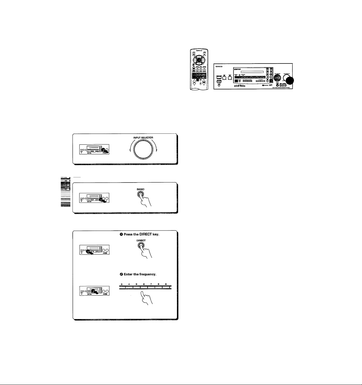
I
Set the input to tuner.
Setect a broadcast band.
Keys or controls used in this operation.
The input sources change as follows:
- ® TUNER (Frequency display)
(D IRPE I (riD)
d) i'lJJEO 1
® t'lIEuE
(D^'IDEOa
(D Ti'/CR2LE
® LD
(DED
. (D PHOi'JG
Each press switches the band as follows:
r^QFM
l-(2)AM
"AM" or"FM" is displayed
Frequency display
U U »H.
Enter the frequency.
Press the numeric keys in the following order:
« AM 10 kHz/FM 100kHz tuning space (U.S.A., Canada, etc.)
AM 810 kHz, press.
AM 1260 kHz, press
FM 90 MHz, press
FM 102.5 MHz, press
.....
.....
.......
........
[ZJ/IJZI
[T|,[1],[I]
f^,[^,[o]
[l|,[o],[g,[^
* AM 9 kHz/FM 50 kHz tuning space (other countries)
AM 810kHz,press
AM 1260 kHz, press
FM 90MHz,press
FM 102.5 MHz, press
FM DE-EMPHASIS/CHANNEL SPACE switch.
• If you make a mistake entering the frequency, the frequency display
will blink for a few seconds. In this case, start again from step U.
..............
..........
...............
........
Frequency display
83.8^^
®,[l],0
[l], ®, [s], [o]
,
[ol, fo1, fo1
.0
* •
.lU
"TUNED" is displayed when a station is reed
Page 29

PtBpStQtionS »Tune to the station you want to store. -[S!
• Press the RECEIVER key on the remote to
activate the receiver mode.
Presetting radio stations
O Press the MEMORY key while
receiving the station.
Keys or controls used in this operation.
Lights for 5 seconds
lioo
Proceed to step © within 5 seconds
(Ifyou wait longer than 5 seconds, repeat
step 0.1
© Enter a preset number (1~40).
Press the numeric keys in the following order:
For "15", press |+10|,iK|
For "20", press , |o]
e Repeat steps O and © and to store as many stations as necessary,
e If you store a station at a previously used preset, the old station will be
replaced by the new one.
Receiving preset stations
Press the numeric keys in the following order:
For "15", press [+10],r^
For "20", press k10|,l+10|,[o1
• If you make a mistake entering a two digit number, press the l+10] key
several times to return to the original display and start again.
Receiving preset stations in order (P-CALLI
Each time you press the key, another preset station is received in order.
When you press
When you press
Holding down the button, lets you skip through the presets,
receiving each for 0.5 seconds apiece.
pq nn
UU.
¡5
. .3B-33-WI
. .38^33^30^
□ o nn
U .UU
‘5-^3^ ....
-3^3*
Page 30

iWlIMUS^MSiL
This receiver incorporates 4 different sound modes to let you enjoy surround sound with a wide variety of program sources.
The Dolby AC-3 and Dolby Pro Logic surround sound let you enjoy theater-like surround effects when you play Dolby AC-3 and
Dolby Pro Logic program sources (like Laserdiscs). Dolby 3 Stereo creates a panoramic frontal sound field while keeping dialog
^^8 on screen. The Digital Signal Processing (DSP) modes, DSP Logic, let you create the atmosphere of a movie theater from almost
any type of program source.
To obtain the best possible surround sound, be sure to complete "Surround set up" before using the surround modes.-»Q^
KR-VS90D CEnJ
Sound modes
Dolby AC-3
The Dolby AC-3 surround format lets you enjoy up to 5.1
channels of digital surround sound from Dolby AC-3 program sources (such as Laserdisc software marked
gjlDo^iu^^ }. Compared with previous Dolby surround,
Dolby AC-3 provides even better sound quality, greater
spatial accuracy, and improved dynamic range.
Some AC-3 programs carry information that lets you com
press the dynamic range of the sound track, without de
grading the sound quality, for softer sound effects when
you listen late at night ("Midnight mode"-[^).
Note
Although a full set of speakers (front left, right, and center, rear left and
right, and a sub-woofer) is required for true 5.1 channel Dolby AC-3
surround sound, this receiver lets you enjoy Dolby AC-3 (and Dolby Pro
Logic) program sources, even if you connect only the front and rear, or
center speakers. ("Surround set up"
Dolby Pro Logic
Dolby Pro Logic is a specially encoded 2 channel surround
format designed to provide theater-like surround sound
from Dolby Pro Logic program sources (such as video and
Laserdisc software marked[lJl«*gyw»wwwD|). This receiver
is equipped with a Dolby Pro Logic surround decoder to iet
you enjoy the wide variety of currently available Dolby Pro
Logic home video software.
Dolby 3 Stereo
Dolby 3 Stereo creates a panoramic frontal sound field
while maintaining the dialog in an on-screen position. This
mode is designed for use with Dolby program sources, but
can also improve sound field unity for non-Dolby program
sources. Dialog positioning and sound image definition,
however, may not be as accurate when used with nonDolby program sources.
* LFE = Low Frequency Extension. This channel delivers separate ndn-
directional bass signals to the sub-woofer for more dynamic deep
bass sound effects.
Although only AC-3 soundtracks incorporate a separate low fjjj
quency channel, connecting a sub-woofer will also improve d(
bass performance in the other surround modes.
* Optional in this mode.
* Optional in this mode.
Page 31

DSP Logic
DSP Logic transforms your listening room into either a
SMALL or LARGE movie theater by using DSP to add delay
and reverberation to signals processed by the Dolby Pro
Logic surround decoder. These modes are most effective
with Dolby Pro Logic program sources, but can also create
a convincing theater-like atmosphere from a (non-Dolby)
stereo signal.*
The EFFECT level lets you adjust the "presence" of the
theater according to your preference.
*Spatial dynamics and sound image definition may not be as accurate
when used with non-Dolby Pro Logic program sources.
* Optional in this mode.
What's DSP?
DSP stands for Digital Signal Processor.
The way a sound is heard in an actual environment
lepends on a variety of different factors. One of the most
' portant is reverberation (the act of decaying elements
W'
Tf sound echoing in various places).
The DSP modes produce the feeling of presence by using
the DSP to create reverberation, without spoiling the
sound quality of the original signal.
Manufactured under licence from Dolby Laboratories Li
censing Corporation. "Dolby",“AC-3“,"Pro Logic" and the
double - D symbol are trademarks of Dolby Laboratories
Licensing Corporation.
Page 32

DOLBY AC-3 can be used when playing LD software bearing the g]|«iu»YwwH^] mark and DOLBY AC-3 format digital broad
casts (etc.). DOLBY PRO LOGIC and DOLBY 3 STEREO can be used when playing video or LD software bearing the
rmiDo^YsuHHouwDi mark.
DSP LOGIC can be used with any source. Be sure to complete "Surround set up" before using any of these surround modes.->[^
KR-vggoD (En)
Preparations
•Turn ON related components.
• Complete "Surround set up", -gft]
• Set the input to the component you
wish to play back with surround
sound.
Seiect the SOUND MENU.
O
o
MAIN MENU
= CD SC
, PHONO
Ituner ffl
]TAPE1 Iffi
SC
□TAPE2M0NIT0R
I Select a surround mode.
Select the icon for the mode you desire. The selected icon turns blue.
AUTO
Shows the speakers selected in
SURROUND SETUP
SOUND MENU
Qj cà '[a
---- as
tu ^ IM
1 STEREO 1
1 AUTO 1 1 l.n'nK: I 1 3 STEREO 1 1 H
fMlNl ^11
This mode selects the appropriate Dolby sur
round mode automatically.
When a Dolby AC-3 format signal is input, the
surround mode switches to DOLBY AC-3.
Otherwise, the surround mode is set to DOLBY
PRO LOGIC. In some cases, depending on
the number of channels being input and the
type of speakers connected, the surround
mode may switch to DOLBY 3 STEREO.
DOLBY PRO LOGIC
Selects the DOLBY PRO LOGIC mode.
VIDE01
VI0E02
VIDEOS
TVDCABLE
LD
, - - ^ -“r
o
SOUND MENU
1
L [
1 Ò1 1 R1 IstraUhtI
ESl ® Isf rm1
1 AUT() 1 1 lS: I IsstehLI I 1
fMAiNi ES
DOLBY 3 STEREO
Selects the DOLBY 3 STEREO mode.
DSP LOGIC
Turns on the current DSP LOGIC mode.
Press the blue triangle (displayed when DSP
LOGIC is turned on) to switch to the DSP
CONTROL screen and set the DSP LOGIC
mode and effect level.
LINE STRAIGHT
Lets you enjoy stereo playback with high
sound quality.
Midnight mode -QS)
I Start playing the video software.
t When playing sources in the Dolby AC-3 surround mode, the sound being
played back may be interrupted until the receiver confirms that an AC-3
signal is being input (until the AC-3 indicator lights).
STEREO
Cancels surround playback.
Adjust the volume.
To enjoy Dolby AC-3 surround (as well as all the other surround modes) from a single component, be sure to use a Dolby AC-3 compatible source
component. Connect the Dolby AC-3 compatible source component's AC-3 format digital audio signal to the AC-3 INPUT terminal on the back
of the receiver. Connect the normal audio signal correctly to the respective component's AUDIO jacks.
Page 33

¿;3S?4.1í*6;:-gsSÍ:
To select a DSP LOGIC mode
Pressing the blue triangle (displayed when DSP LOGIC is turned on} in the DSP LOGIC icon on the SOUND MENU, displays the DSP
CONTROL screen. Set the DSP LOGIC mode and EFFECT LEVEL as you desire.
DSP CONTROL
DSP LOGIC mode setting
LARGE ; Simulates the presence of a
large movie theater.
SMALL : Simulates the presence of a
relatively smaller movie
theater.
■TPSF LOGIC ; -
iï^ÜLABGi
¡-□SMALL :________
.
Í1M1 m @
...................
level: ■
ill i:'
...
--------—
EFFECT LEVEL setting
Lets you choose from three different effect levels.
Convenient functions
Midnight mode (Dolby AC-3 mode oniyj
When watching movies at night you might not be able to raise the
volume as loud as normal. Midnight mode compresses the dynamic
range of previously specified parts of the AC-3 sound track (like scenes
with sudden increases in volume) to minimize the difference in volume
between the specified and non-specified parts. This makes it easy to
hear all of the sound track, even when listening at low volumes.
Press to switch.
On
- Yellow
- Dark grey
The indicator on the receiver also lights
• Some Dolby AC-3 software may not be compatible with the Midnight
mode.
• Midnight mode has no effect on parts of the sound track that are not
specified for compression.
Off
- Same color as screen
DIMMER switch
The dimmer switch lets you adjust the brightness of the receiver's
display in three levels. You might find this useful if you darken your
room to watch movies or iisten to music.
^SPLAYMODEkey
Each time you press the DISPLAY MODE key on the remote control,
the information shown in the receiver's display changes between the
current input source and the current surround mode.
Press to switch.
Off Dimmer-1 Dimmer-2 Off
Blue Grey Yellow Blue
S”
1 Tf
L. H
PRO
, nr T r ^
L. UÜ X L-
ST"
t
Page 34

Refer to the following table for the type of remote control operations available for each video component. Each key on the table
operates the selected component as shown in the respective column. {The set up code for each component must be entered
beforehand. -»QS) ^ . , r—
Howto ooerate video components
...
' —;i: .1: ~
.
.........
.
"Connecting the repeater"
"System set up"
KR-V990D tEn)
I Turn on the receiver.
I Set the input selector to the component you
want to control.
I Use a component control selection key to
select the component you want to control.
I Refer to the "Remote control key operation
table" and press the key corresponding to the
• Be sure to point the remote control at the IR receptor on the receiver
when operating the remote control, even when operating other com
ponents.
Although each setup code is designed to work with a number of different models, certain codes may not work with some models. (Also, certain
codes may only operate some of the functions available on a given model.)
Page 35

VCR Set up codes
Maker
ADVENTURA 015
AIKO 293
AIWA
MAI
ASHA 255
AUDIOVOX 052
BEAUMARK 255
BELL & HOWELL119
BROKSONIC
CALIX
CANON 050,182
CAPEHART
CARVER
CCE
CITIZEN 052,293
COLT 087
CRAIG
CURTIS MATHES050,056,075
CYBERNEX 255
DAEWOO
DAYTRON 035
DYNATECH 015
ELECTROHOME
ELECTROPHONIC
EMEREX 047
EMERSON
FISHER
FUJI 048,050
Mnai 015
GE
GO VIDEO
GOLDSTAR 033,052,053
GRADIENTS 015
HARLEY DAVIDSON015
HARMAN/KARDON053,090
HARWOOD 087
HEADQUARTER061
Hl-Q 062
HITACHI
JENSEN
JVC
KENWOOD 053,056,082
KLH 087
KODAK
LLOYD
LLOYD'S
LOGIK
LXI
MAGNAVOX
MAGNIN 225
MARANTZ 050,096
MARTA
MATSUSHITA 050
MEI 050
M^MOREX
Л
Ba 058,076
i
MGN TECHNOLOGY255
MINOLTA 057,120
MITSUBISHI
MOTOROLA 050,063
015
056,064,068,076,257
050
136,199^26,310,376
052
035
096
087,293
052,062,087255,286
035,060,102,293
052
052
015,017,052,058,076,136,199,223,224,226,227,309,
310,376
062,069,081,119
015
050,075,080^17
247,294
056,057,080,097,120,181
056
023,056,082
050,052
015
223
087
052
050,054,096,125,164
052
015,050,052,054,061,062,063,119,225
058,076,082,090,188^29,257
Set up codes
Maker
MTC
MULTITECH
NAD
NEC
NIKKO
NOBLEX
OLIMPUS
OPTIMUS
OPTONICA
PANASONIC
PENNEY
PENTAX
PHILCO
PHILIPS
PILOT
PIONEER
PORTLAND
PROTEC
PULSAR
QUARTER
QUARTZ
QUASAR
RADIO SHACK
RADIX
RANDEX
RCA
REALISTIC
RICOH
RUNCO
SAMSUNG
SANKY
SANSUI
SANYO
SCOTT
SEARS
SHARP
SHINTOM
SHOGUN
SINGER
SONY
STS
SYLVANIA
SYMPHONIC 015
TATUNG
TEAC
TECHNICS
TEKNIKA
TMK
TOSHIBA
TOTEVISION 052Д55
UNITECH
VECTOR
VECTOR RESEARCH
VIDEO CONCEPTS055,060,076
VIDEOSONIC 255
WARDS
XR-1000
YAMAHA
ZENITH
1
015,255
Set up codes
015,087
073
053,055,056,065,082,097
052
255
050,241
052,063,073,119
077
050,092,240,241
050,052,053,055,057,069,255
057,080,120
050
050,077,096,125
052
073,082
035
087
054
061
061
050,092
015,052
052
052
057,075,080,092,120,164,217
015,050,052,061,062,063,077,081,119,255
049
054
060,068,255
054,063
056,082,097,286
061,062,119Д55
058,060,136,199,225,226Д27
050,052,057,061,062,069,081,119,120
063,077
087
255
087
047,048,049,050
057
015,050,058,096,125
056
015,056
050,177
015,050,052,067
223,255
058,060,081 Д25,227
255
060
053,055
015,050,057,062,063,077,087,164,227 Д55
015,050,087
053
048,049,054
KR-vggoD (En)
Page 36

TV Set up codes
Maker
A-MARK
ABEX
ADMIRAL
ADVENTURA
AIKO 107
AKAI
ALARON 231
ALLERON
AMBASSADOR
ANAM
ANAM NATIONAL
AOC
ARCHER 018
AUDIOVOX
BELCOR 034
BELL & HOWELL
BRADFORD 195
BROCKWOOD
BROKSONIC
CANDLE
CARVER
CCE
CELEBRITY
CITIZEN 045,054,061,071,075,107,201,295
CLAIRTONE
CONCERTO 071
CONTEC 173,195,200
CRAIG 195
CROWN
CURTIS MATHES045,054,075,169
cxc
DAEWOO
DAYTRON
DUMONT
DYNATECH
ELECTROBAND015,200
EMERSON
ENVISION
FISHER 169,174
FUJITSU 194
FUNAI
FUTURETECH
GE
GIBRALTER
GOLDSTAR
GRUNPY
HALLMARK 193
HARVARD 195
HITACHI
IMA
INFINITY 069
JANEIL 061
JBL
JCB
JENSEN 065
JVC 051,068,197
KAMP 231
KAWASHO
KAYPANI
KENWOOD
KLOSS 039,061
KMC
018
047
108
061
045,113
194,198
192
019,195
070
018,034,045,067,152,200
018,195
031,169
034
018
045,061,071,201
069
232
015
200
054,195
195
034,054,106,107,466
034
032,034
064
034,053,054,169,173,192,193,194,195,196,197,198,
200,251,285,295,297,478
045
194,195
195
036,042,044,062,066,070,150,189,193,297
032,034,045
016,017,034,045,047,054,071,121,193
194,195
047,053,071,110,112,160,166,188,242
195
069
015
173^31,323
067
034,045,171
121
Set up codes
Maker
KTV
LOGIK
LUXMAN 071
LXI 062,069,163,169,171,193
MAGNAVOX 045,051,069,111,201 '
MAJESTIC 031
MARANTZ
MATSUI
MEGATRON 018,160,093
MEI
MEMOREX
MGA 034,045,165,170,193
MIDLAND 032,047,054,062,066,150
MINUTZ
MITSUBISHI 034,113,165,170,193
MOTOROLA 070,108
MTC
MULTITECH
NAD 171,181,193
NEC 034,045,051,071,185
NIKKO
NTC
ONWA
OPTIMUS 169,181
OPTONICA
ORION
PANASONIC 066,069,070,177,265,353
PENNEY
PHILCO
PHILIPS
PILOT
PIONEER
PORTLAND 034,054,107
PRICECLUB
PRISM
PROSCAN 062
PROTON
PULSAR
PULSER
QUASAR
RADIO SHACK034,047,054,180,195
RCA
REALISTIC
RHAPSODY
BUNCO
SAMPO
SAMSUNG
SAMSUX
SANYO
SCIMITSU
SCOTCH
SCOTT
SEARS
SHARP
SHOGUN
SIGNATURE 031
SIMPSON
SONY 015,026,095,126,288
SOUNDESIGN
SPECTRICON018,152
SQUAREVIEW186
SSS
045,054,195,198,200,232,295
031
045,069
232
200
031,071,121,165,169,193
036
034,045,064,071,075,106,200
064,195,232
045,107,193,332
107
195
108,180
251
017,018,033,034,036,042,045,047,054,062,066,075,
125,150,164,171,193
034,045,069,111
069
034,045,054 41'
053,181
075
066
018,046,067,193
032
034
066,070^65
033,034,044,053,062,105,150,189
034,045,047,054,071,169,180,193,195
198,200,231
032,045
045,047,054,067,115,125
034,045,047,054,071,075,125,193
054
161,169,174
034
193
034,193,194,195,251
062,069,071,161,163,164,169,171,174,186,193,194
054,108,180
034
201,202 ^.
193,194,195,201
034,195
Set up codes
Page 37

TV Set up codes
Maker Set up codes
STARLITE 195
SUPRE-MACY061
SUPREME 015
tf|LVANrA 045,069,080,111
Hviphonic 186
TANDY 108
TATUNG 018,064,070
TECHNICS
TECHWOOD 066,071
TEKNIKA
TERA 046
TMK 071,192193
TOSHIBA 051,075,164,169,171
TOSONIC 200
TOTEVISION054
ULTRA 406
UNIVERSAL 042
VECTOR RESEARCH045
VICTOR 068,265
VIDEO CONCEPTS113
VIDEKRON 069
VIDTECH 034,193
VIKING 061
WARDS
YAMAHA 034,045
ZENITH 031,032
ZONDA 018
066,265
031,034,054,069,071,075,107,165,194,195,201,327,
337
031,034,035,036,042,043,044,045,069,071,095,111,
126,180,189,193,194
able Set up codes
^^Maker
ABC
ANTRONIX 222
ARCHER 054,168,222
CENTURY
CITIZEN 168
COLOUR VOICE040,046
COMBAND 247,248
COMTRONICS055,075
CONTEC 034
EASTERN 017
ELECTRICORD
FOCUS 415
GARRARD 168
GC ELECTRONICS222
GE
GEMINI 030,072,085,257
GENERAL INSmUMENT026,291
GOLDSTAR 055159
HAMLIN
HITACHI 026
HITEX 022
JASCO 168
JERROLD 018,026,027,029,030,039,062,113,291
MACOM 048
MAGNAVOX 042
I^MOREX 015
Movie time 078,093,171
NORTHCOAST
NSC
OAK 022,034,263
PANASONIC 036,122
016,018,022,023,026,028,029,032,062
168
093
247,248
024,035,049,274,288
329
078,085,171
Set up codes
Maker
PARAGON 015
PHILIPS
PIONEER
POPUL AR ME CH AN ICS
PULSAR 015
RCA
REALISTIC 222
RECOTON 415
REGAL 035,274,288,294
REGENCY
REMBRANDT026,085
RUNCO
SAMSUNG 055,159
SCIE NT IFI C A TL ANTA
SIGNAL 030,055
SIGNATURE 026
SL MARX 055
SPRUCER 036,322
STA ND Affi) C OM PO NE NT S
STARCOM 018,030,062,113
STARGATE 030,055
STARQUEST030
SYLVANIA 016
TANDY 273
TATUNG
TEKNIKA 161
TELECAPTION236
TELEVIEW 055
TEXSCAN 016,111
TOCOM 027,028,074
TOSHIBA 015
TUSA 030
TV86 078
UNIKA 168,222
UNITED ARTISTS
UNITED CABLE018
UNIVERSAL
VIDEOWAY 265
VIDTECH 259
VIEWSTAR 042,075,078,226,273,304
ZENITH 015,069
ZENTEK
040,042,043,044,045,046,168,257,305
038,159,275
415
036
017
015
021,023,032,292
111
112
022
054,092,093,168,206,222,337
415
Set up codes
LD Set up codes
Maker Set up codes
AIWA 218
CARVER
DENON 187
FUNAI 218
KENWOOD 273
MAGNAVOX
MARANTZ
MITSUBISHI 074
NAD 074
PANASONIC 219
PHILIPS 079
PIONEER 074
QUASAR 219
RCA 366
REALISTIC 218
SHARP 016
SONY 208,216
YAMAHA 232
079
232,256
079
Page 38

Satellite Set up codes
Maker
BIRDVIEW 060
CHANNEL MASTER033
CHAPARRAL
CITOH
DRAKE
ECHOSTAR
GENERAUNSTRUHENT053,065
MACOM
MEMOREX
PROSAT
RCA
REALISTIC
STS
UNIDEN
ZENITH 079
068
179
033,079
163,174,233,284,295,327
033,065
284
173
581
067
052
067,089,091
Set up codes
Notes for using cable television or satellite broadcast reception equipment
Please note that the input selector and the components which can be used with this receiver vary according to the region in which
it was purchased.
TV/CABLE: Lets you input signals from a TV or cable TV receiver and enter TV or cable TV set up codes.
TV/SAT: Lets you input signals from a TV or satellite receiver and enter TV or satellite receiver set up codes.
The specifications for each region are as follows.
Region
FM DE-EMPHASIS/CHAN-
IMEL SPACE switch position
Input selector name
Functional set up codes
For U.S.A., Canada and
South American countries
For Australia
For other countries
(The specifications change ac
cording to the position of the
FM DE-EMPHASIS/CHANNEL
SPACE switch.) -Ca
Some set up codes cannot be used in certain regions.
“^PHASIS
■ LJt saiis
AM9kHz
FMsaicHi
nr ’5|iS
SPAES
AM9k№
I^ISOkHz
,00kHz
SOiiS
TV/CABLE
TV/SAT.
TV/CABLE
TV/SAT.
TV or Cable
TV or Satellite
TV or Cable
TV or Satellite
Page 39

The following chart shows all the menus that can be displayed in the OSD mode. Use this chart as a reference to determine the
position of the current menu when using the GUI control mode. The numbers proceeding the menu names correspond to the
numbers in "Screen menu structure".
(D MAIN MENU
KR-V990D (En)
-□2
Switches to the operation menu for the
respective component.
Switches to the SOUND MENU.
Switches to the SET UP menu.
Sound menus
SETUP
□SURROUND SET UP
□SYSTEM SETUP
1ШГ
®SPEAKER
SELECTION&DISTANCE
ШШ ЕШ-ЩТТЩ!
w
DELAYTIME ìS^ZOm АИ05ш
CD SPEAKER LEVEL
SPEAKER LEVEL
I I и I ! M I I H I M t I ! I |>
Ш ПЯ ШГ
tEH Ш LS OdB
Ш TONE TYPE
□OFF OAUTO OMANUAL
I MAIN I_IbackI 1h5t| |Q3l
RS OdB
SW OdB
!►
__________
) SYSTEM CONTROL
SYSTEM CONTROL
SYNCHRO MODE
□SL16 OXS8
LD SET UP
OIR REMOTE OSYNCHRO
TAPE1 MD SET UP
□TAPE DMD
ШШ Ш Ш Ш'М
® IR REMOTE CONTROL
IR REMOTE CONTROL
OLD
0V1DEO1
□VIDEOS
ШШ ИИШ1Ш1С
TV
CABLE
В
□SET ICD 0POWER
_____
) MACRO SET UP
MACRO SET UP
INPUT □
TV ?№VE
mi
TV INPUT“ 'П
SOUND OSTE
ШГ
^
\ / ▼
d) SOUND MENU
SOUND MENU
Ш ГШ Ш
[Ш Ш Ssl
1 ^UTQ 1 1 1.Ж 1 1i
ГмШ
D DSP CONTROL
\
\
1атвЧ1иг1
rsTÈlÈóì
ш Ш
) INPUT LEVEL
INPUT LEVEL
□CD
□PHONO
□TUNER JVIDE03
□TAPE1
□TAPE2‘M0N1T0R
1 MAIN 1 laljcj
\
QVIDE01
]VIDE02
Itv/cable
JLD
Ш
......
continued on next page
Page 40

Operation menus
(g)IVID ©TV
\
TV
CHANNEL lEl
TRACK NO,
i№i
] a M
i> VIDEO 1
^ VIDEO 2
VIDE02
1^ CHANNEL
B - H
fMÀìNimr E
1. Refer to the operating instructions supplied with each connponent for details regarding their operation.
™ 2. Selecting PHONO or VIDEO 3 from the main menu only switches the INPUT.
Wiss; 2, The operation screens are displayed in black and white when video signals are being input to the TV.
4. Some of the contents displayed may vary according to the operation mode.
Hi
flDEO
mm H M
® CABLE
CABLE
□MUTE
fMÀÌNl M
® LD
LD
QEEIH
@ VOLUME m
□MUTE
S CHANNEL fEl
B VOLUME M
iB
PÓMI
iVi
Page 41

itticiiV
Resetting the Microcomputer
If the microcomputer may malfunction (unit cannot be operated, or
shows an erroneous display) if the power cord is unplugged while the
power is ON, or due to some other external factor. If this happens,
execute the following procedure to reset the microcomputer and
^turn the unit to its normal operating condition.
Amplifier
No sound from the speakers.
The standby indicator blinks and sound is
not output.
• The speaker cords are disconnected.
e VOLUME is set to the minimum position.
• MUTE is ON.
(The MUTE indicator is blinking)
e The SPEAKERS switches are set to OFF.
• The TAPE 2(MONITOR) key is set to ON.
• Speaker cords are short-circuited.
KR-V99GD (En]
With the power cord plugged in, turn the MAIN POWER
key OFF. Then, while holding down the REMOTE POWER
key, press MAIN POWER.
• Please note that resetting the microcomputer will clear the contents
of the memory and returns the unit to the state it was in when it left
the factory.
Reinedy
• Connect them properly referring to "Connect
ing the speakers" -[42
• Adjust the volume to a proper level.
• Turn OFF the MUTE.
(use the remote)
• Set the SPEAKERS switch(es) to ON. -[^2
• Set the TAPE 2(MONITOR) key to OFF.
• Turn the power off, eliminate the short-
circuiting, then turn on the power again.
Sound is not output from one of the speak
ers.
Sound is not output from the rear (sur
round) speakers and/or the center speaker,
or their sound is very small.
jj^ humming noise is generated when the
PHONO input selector is selected.
• The speaker cord is disconnected.
• The BALANCE control is set to an extreme
position.
• Therearspeakercordsand/orthecenterspeaker
cord is disconnected.
• A surround mode has not been engaged.
• The REAR VOL. and/or CENTER VOL. controls
are set to the minimum level.
• The audio cord from the turntable is not con
nected to the PFIONO jacks.
• The turntable is not grounded.
Tuner
Radio Stations cannot be received • No antenna is connected.
Interference
A station which was preset cannot be re
ceived by pressing the corresponding nu
meric key.
• The broadcast band is not set properly.
• The frequency of the desired station is not
tuned.
• Noise due to ignition noise from an automobile.
• Noise due to interference from an electric
appliance.
• Noise due to a nearby TV set.
• The preset station belongs to a frequency that
cannot be received.
• The preset memory was cleared because the
power cord had been unplugged for a long
period of time.
Cause
• Connect it properly referring to "Connecting
the speakers".
• Adjust the Left/Right balance.
• Connect it properly referring to "Connecting
the speakers",
• Select a surround mode.
• Adjust the REAR VOL. and CENTER VOL con
trols.
• Insert the audio cord plugs securely into the
PHONO jacks.
• Connect the grounding wire to the GND termi
nal on the rear panel.
Remedy
• Connect an antenna.
• Set the broadcast band properly.
• Tune the frequency of the desired station.
• Install the outdoor antenna away from the road.
• Turn off the power to the appliance.
• Install the receiver farther away from the TV.
• Preset a station with a receivable frequency.
• Preset the station again.
.
Page 42

Remote control unit
._%mptoW
Remote control operation is not possible.
Do not use contact cleaning agents because they could case a malfunction. Be specifically careful against using contact cleaning agents
containing oil, since they may deform the plastic components.
• Batteries are exhausted.
• The remote control unit is too far away from the
main system, controlling angle is too large, or
there is an obstacle between the receiver and
the remote.
• The audio cords and system control cords are
not connected properly.
• No software is loaded in the source compo
nent.
• An attempt is made to play a tape which is
being recorded in the cassette deck.
• The remote control has not been set to the
operation mode for the component you wish to
control.
Cause
Remedy
» Replace with new batteries. -[5]
> Operate the remote control unit within tf^
controllable range.
• Connect properly referring to "System connec
tions". -1X1
• Place software in the source component you
want to play.
• Wait until recording has completed.
• Press the component control selection key
corresponding to the component you wish to
control to activate the respective control mode
before operation. -iXl-lX]
FortheU.S.A.
FCC WARNING
This equipment may generate or use radio frequency energy. Changes or modifications to this equipment may cause harmful interference unless
the modifications are expressly approved in the instruction manual. The user could lose the authority to operate this equipment if an unauthorized
change or modification is made.
NOTE:
This equipment has been tested and found to comply with the limits for a Class B digital device, pursuant to Part 15 of the FCC Rules. These limi^
are designed to provide reasonable protection against harmful interference in a residential installation. This equipment may cause harmfH
interference to radio communications, if it is not installed and used in accordance with the instructions. However, there is no guarantee that
interference will not occur in a particular installation. If this equipment does cause harmful interference to radio or television reception, which can
be determined by turning the equipment off and on, the user is encouraged to try to correct the interference by one or more ofthe following measures;
- “ Reorient or relocate the receiving antenna.
-- Increase the separation between the equipment and receiver.
--Connect the equipment into an outlet on a circuit different from that to which the receiver is connected.
- - Consult the dealer or an experienced radio / TV technician for help.
For the U.S.A.
Note to CATV system instalier:
This reminder is provided to call the CATV system installer's attention to Article 820-40 of the NEC that provides guidelines for proper grounding
and, in particular, specifies that the cable ground shall be connected to the grounding system of the building, as close to the point of cable entry
as practical.
Memory back up function
Please note that the following items will be deleted from
the receiver's memory if the receiver is not turned on for
a period of approximately 3 days.
• Power mode.
• SYSTEM CONTROL MODE setting.
• Settings made using OSD (like SYSTEM SET UP and SURROUND
SET UP).
• Input selector settings (including MD and LD).
• Volume level.
• Broadcast band.
• Frequency setting,
t stations.
Page 43

ecifications (For U.S.A. and Canada
■Tl
Rated power output during STEREO operation
120 watts per channel minimum RMS, both channels
driven, at 8 Q from 20 Hz to 20 kHz with no more than
0.03 % total harmonic distortion.(FTC)
Red power output during SURROUND operation
Front
_____________________________________
105 watts per channel minimum RMS, both channels
driven, at 8 Q, 1kHz with no more than 0.7 % total
harmonic distortion.
Center
105 minimum RMS at 8 Q, 1 kHz with no more than 0.7
% total harmonic distortion.
Rear
70 watts per channel minimum RMS, both channels
driven, at 8 O, 1kHz with no more than 0.7 % total
harmonic distortion.____________________________
Total harmonic distortion
Frequency response
LINE(CD, AUX, TAPE)
Signal to noise ratio (IHF'66)
PHONO(MM)
LINE(CD, AUX, TAPE)
Input sensitivity / impedance
PHONO (MM)
LINE(CD, AUX, TAPE)..............................200 mV / 47 kO
Output level / impedance
TAPE REC................................................
PRE OUT (FRONT, CENTER, REAR, SUBWOOFER)
..........................................................................
^^me Control
BASS....................................................
TREBLE............................................. ±10 dB (at 10 kHz)
LOUDNESS control
VOLUME at -30 dB level
...............
......
10 Hz ~ 75 kHz, + 0 dB, -3 dB
..............................................................
...............................................
.............................................2.5 mV / 47 kO
.......................
____________
0.005%(1 kHz, SOW, 8 Q)
200 mV / 2.2 kO
±10 dB (at 100 Hz)
+8 dB (at 100 Hz)
75 dB
98 dB
1 V/1 kO
FM tuner section
Tuning frequency range........................87,5 MHz 108 MHz
Usable sensitivity (MONO)
.........
50dB quieting sensitivity
Total harmonic distortion (1 kHz)
Signal to noise ratio (1 kHz, 75 kHz DEV.)
Selectivity (±400 kHz)
Stereo separation (1 kHz)
AM tuner section
Tuning frequency range.........................530 kHz - 1.700 kHz
Usable sensitivity (30% mod., S/N 20 dB)
Total harmonic distortion
Signal to noise ratio (30 % mod. 1 mV input)
Selectivity......................................................................... 30 dB
Power consumption
AC outlet
Dimensions......
Weight (Net)...................................................13.1 kg (28.9 lb)
1.2pV (75 i2)/ 13.2 dBf (75 kHz DEV., S/N 30 dB)
STEREO
.................
32pV (75 O)/ 41.2 dBf (75 kHz DEV.)
MONO
...........................................0.6 % (65.2 dBf input)
STEREO
..........................................
MONO............................................. 75 dB (65.2 dBf input)
STEREO
.........................................
......................................................
Frequency response
...................................................... 16 pV / (500 pV/m)
GENERAL
SWITCHED.............................2 (total 150 W, 1.2 A max.)
.
..................................................
.
..................................................D :396 mm (15-9/16")
......................................................
......
....
...............................................0.7 %
.........................................................
................................
0.7 % (65.2 dBf input)
68 dB (65.2 dBf input)
30 Hz - 15kHz,+0.5 dB, -3.0 dB
...............
W: 440 mm (17 - 5/16")
H :162 mm (6-3/8")
50 dB
45 dB
5.2 A
40 dB
DIGiTALAUDiO section
Sampling frequency .......................32 kHz, 44.1 kHz, 48 kHz
Input level / impedance
Coaxial (TV/CABLE)..................................0.5 Vp-p / 75 a
VIDEO section
TELEVISION format
VIDEO inputs / outputs
VIDEO (composite)
S-VIDEO (luminance signal)
.........................................................NTSC
......................................
(chrominance signal)
KENWOOD follows a policy of continuous advancements in development. For this reason specifications may be changed without notice.
.......................
..........
0.286 Vp-p / 75 Q
1 Vp-p / 75 ii
1 Vp-p / 75 O
Page 44

ions (For other countries
AUDIO section
Rated power output during STEREO operation
(EIAJ) 1kHz,10% T.H.D.,at 8 Q
{DIN/IEO at 8 O..........................................120 W + 120 W
Rated power output during SURROUND operation
FRONTdkHz, 10% T.H.D. at 8 Q)
CENTER mHz, 10% T.H.D. at 8 Q)...........................150 W
REARdkHz, 10% T.H.D. at 8 O)
Total harmonic distortion
Frequency response
LINE (CD, AUX, TAPE}
Signal to noise ratio (IHF'66)
PHONO (MM).......
LINE (CD, AUX, TAPE)..............................................
Input sinsitivity / impedance
PHONO (MM)
LINE (CD, AUX, TAPE).............................200 mV / 47 kO
Output level / impedance
TAPE REC................................................
PRE OUT (FRONT, CENTER, REAR, SUBWOOFER)
...........................................................................
Tone control
BASS ...................................................±10 dB (at 100 Hz)
TREBLE................................................±10 dB (at 10 kHz)
LOUDNESS control
VOLUME at -30dB level....
......................................................
.............................................
.................
150 W + 150 W
..............
150 W + 150 W
....................
.............
0.005 % (1kHz, 60 W, 8 O)
......
10 Hz ~ 75 kHz, +0 dB, -3 dB
.........................+8 dB (100 Hz)
65 W + 65 W
2.5 mV / 47 kO
200 mV / 2.2 kO
75 dB
98 dB
1 V / 1 kO
ead this page care
KR-V99DD CEn)
FM tuner section
Tuning frequency range........................87,5 MHz ~ 108 MHz
Usable sensitivity (MONO)
.........
1.2pV (75 O)/ 13.2 dBf (75 kHz DEV., S/N 30 dB)
50dB quieting sensitivity
STEREO
Total harmonic distortion (1 kHz)
Signal to noise ratio (1 kHz, 75 kHz DEV.)
Selectivity (±400 kHz)
Stereo separation (1 kHz)
Frequency response
AM tuner section
Tuning frequency range
Usable sensitivity (30% mod., S/N 20 dB)
Total harmonic distortion
Signal to noise ratio (30 % mod. 1 mV input)
Selectivity.........................................................................30 dB
.......... 32pV (75 Cl)/ 41.2 dBf (75 kHz
MONO
.............................................0.6 % (65.2 dBf input)
STEREO
..........................................
MONO............................................ 75 dB (65.2 dBf input)
STEREO
........................................ 68 dB (65.2 dBf input)
......................................................
...............................................
...........
9 kHz step
.........................................530 kHz ~ 1.602 kHz
10 kHz step.......................................530 kHz ~ 1.610 kHz
..........................................................16 pV / (500 pV/m)
...............................................0,7 %
0.7 % (65.2 dBf input)
50 dB
...............
40 dB
45 dB
30 Hz ~ 15kHz,+0.5 dB, -3.0 dB
DIGITAL AUDIO section
Sampling frequency
input level / impedance
Coaxial (TV/CABLE)
VIDEO section
TELEVISION format
VIDEO inputs / outputs
VIDEO (composite)
S-VIDEO (luminance signal)
........................
................................
.....................................
(chrominance signal)
KENWOOD follows a policy of continuous advancennents in development For this reason specifications may be changed without notice.
32 kHz, 44.1 kHz, 48 kHz
.................................0.5 Vp-p / 75 Q
.........................
............
.....
.....
0.286 Vp-p / 75 Cl
1 Vp-p / 75 Ì2
1 Vp-p / 75 Cl
...........
KENWOOD
NTSC
GENERAL
Power consumption ......................................................450 W
AC outlet
SWITCHED (for Australia)
SWITCHED (for other countries)
Dimensions
Weight (Net)...................................................................13.1 kg
For your records
Record the serial number, found on the back of the unit, in the snacei
designated on the warranty card, and in the space provided belowfflB
to the model and serial numbers whenever you call upon your deals™
information or service on this product.
Model_ . Serial Number_
......................................................
.........................................................................
.................
......
1 (total 90 W max.)
2 (total 90 W max.)
W: 440
D : 396 mm
 Loading...