

Page 1

AUDIO/VIDEO STEREO RECEIVER
KR-V9020
INSTRUCTION MANUAL
KENWOOD OORPORATION
n
Page 2
Introduction
Your choice of this product indicates that you are a devotee
to excellence in sound reproduction,
We appreciate your patronage and take pride in the long tradi
tion of quality components that our company represents.
So that you can get the most out of your unit, we suggest that
you take the time to read through this manual before you hook
up and operate your system. This will acquaint you with oper
ating features and system-connection considerations so that
your listening pleasure will be enhanced right from the start.
You will notice that in all aspects of planning, engineering,
styling, operating convenience and adaptability we have sought
to anticipate your needs and desires.
Keep this manual handy for future reference.
For your records
Record the serial number, found on the back of the unit, in
the spaces designated on the warranty card, and in the space
provided below. Refer to the model and serial numbers
whenever you call upon your dealer for information or service
on this product,
Model _________
______
Serial Number,
_____________
__
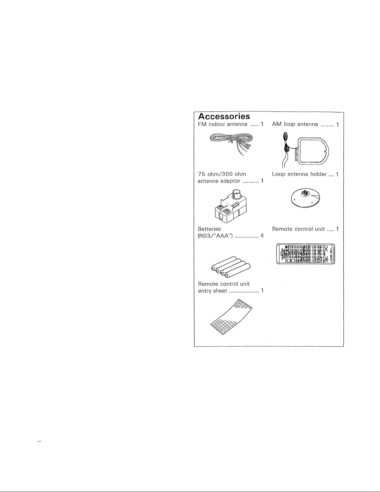
Unpacking
Unpack the unit carefully and make sure that all accessories
are put aside so they will not be lost.
Examine the unit for any possibility of shipping damage. If your
unit is damaged or fails to operate, notify your dealer immedi
ately, If your unit was shipped to you directly, notify the ship
ping company without delay. Only the consignee (the person
or company receiving the unit) can file a claim against the car
rier for shipping damage.
We recommend that you retain the original carton and pack
ing materials for use should you transport or ship the unit in
the future.
For the USA
Note to CATV system installer:
This reminder is provided to call the CATV system in
staller's attention to Article 820-22 of the NEC that pro
vides guidelines for proper grounding and, in particular,
specifies that the cable ground shall be connected to the
grounding system of the building, as close to the point
of cable entry as practicah
Contents Caution: Read the
Introduction.................................................................. 2
A Before applying power
A Safety precautions .................................................... 3
A IMPORTANT SAFEGUARDS
System connections......................................................... 6
Speaker connections
Antenna connections................................................... TO
FM DE-EMPHASIS/CHANNEL SPACE switch
System control operation
.................................................
...................................
....................................................
..............
.............................................. 1 2
3
4
8
1 1
pages marked ^ carefully to ensure safe operation.
Listening to broadcasts
Graphic equalizer operation
Playing video sources
Surround effects,,,
System memory
On-screen display
Remote control operation .............................................. 35
In case of difficulty
Specifications ..................................................................43
....................................................
............................................
.................................................... 26
................
.............................................................
............................................................
...........................................................
........................................ 28
20
24
32
33
42
Page 3
Before applying power
Acaution: Read this page carefully to ensure safe operation.
For the U.S.A. and Canada
important!
Units shipped to the U.S.A. and Canada are designed for opera
tion on 120 volts AC only.
Safety precaution for a Polarized AC plug
However, some products may be supplied with a non-polarized
plug,
CAUTION: TO PREVENT ELECTRIC SHOCK DO NOT USE
THIS (POLARIZED) PLUG WITH AN EXTENSION CORD,
RECEPTACLE OR OTHER OUTLET UNLESS THE BLADES CAN
BE FULLY INSERTED TO PREVENT BLADE EXPOSURE.
For the United Kingdom
Important!
Units shipped to the U.K. are designed for operation on
240 volts AC only.
The mains plug must be removed from the wall socket prior
to any internal examination.
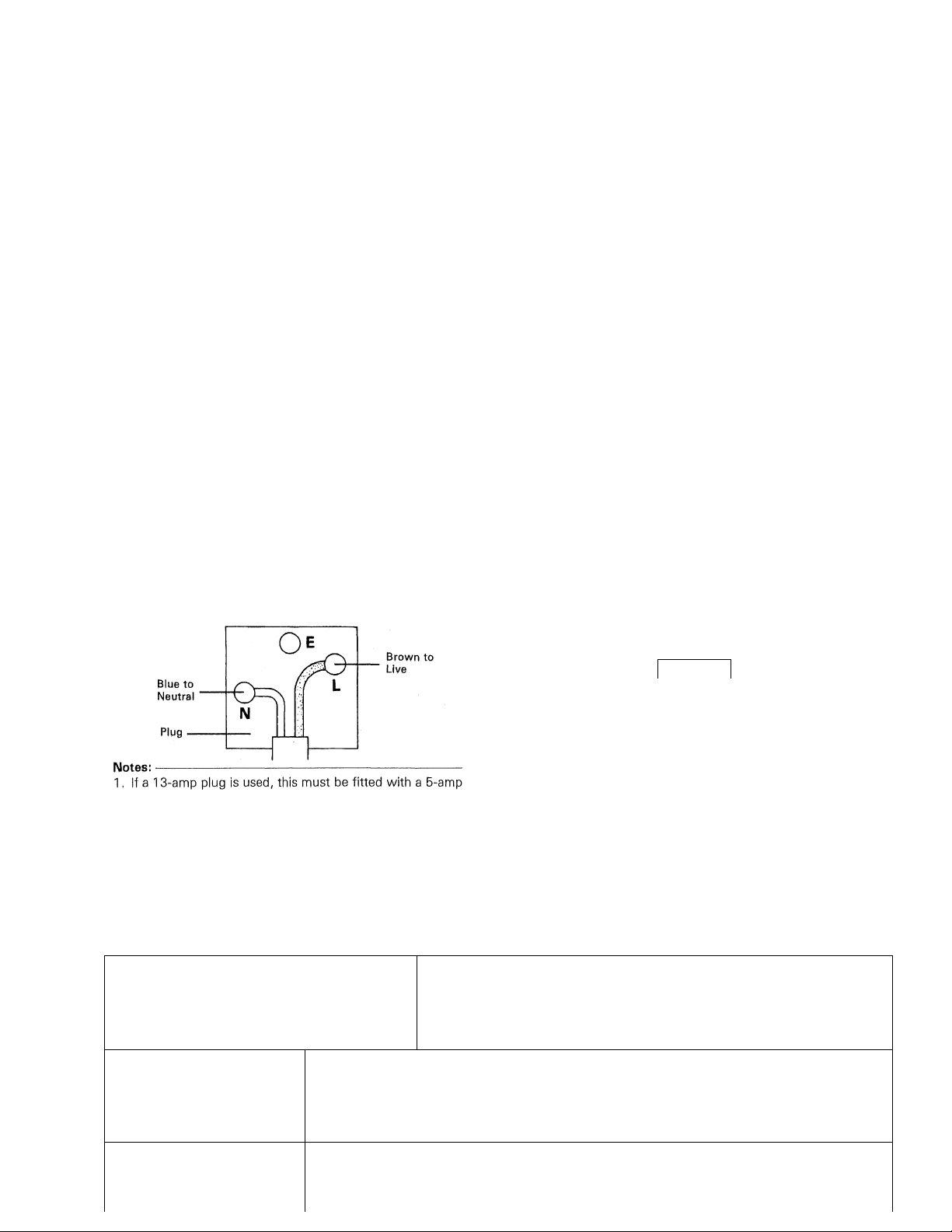
The wires in this mains lead are coloured in accordance with
the following code:
Blue
.............................................
Brown ...........................................
The wires in this mains lead must be connected to the termi
nals in the plug as follows:
Wire colour Plug terminal marking
Blue
............................................. N or Black
Brown
..........................................
Neutral
Live
L or Red
For Australia and Europe
Important!
Units shipped to Australia are designed for operation on 240 V
AC only.
Units shipped to Europe are designed for operation on 220 V
AC only.
For other countries
Important!
Units shipped to countries other than the above countries are
equipped with an AC voltage selector switch on the rear panel.
Refer to the following paragraph for the proper setting of this
switch.
AC voltage selection
This unit operates on 110-120 or 220-240 volts AC. The AC
voltage selector switch Type A or Type B on the rear panel is
set to the voltage that prevails in the area to which the unit
is shipped. Before connecting the power cord to your AC out
let, make sure that the setting position of this switch matches
your line voltage. If not. It must be set to your voltage in ac
cordance with the following direction.
Note:
-------------------------------------------------------------
Our warranty does not cover damage caused by excessive line
voltage due to improper setting of the AC voltage selector
switch.
AC voltage selector switch
---------
Type A
!¡T^PiT'
ill
AC220V-- AC240V-
Type B
fuse.
2. if a 3-pin plug N;^ith earthing contact is used, no wire must
be connected to the E terminal.
AC110V-
120V-
Move switch lever to match your line voltage with
a small screwdriver or other pointed tool.
-AC220V-
240V ~
Safety precautions
WARNING: TO PREVENT FIRE OR SHOCK HAZARD, DO NOT EXPOSE THIS APPLIANCE
TO RAIN OR MOISTURE.
CAUTION: TO REDUCE THE RISK OF ELECTRIC SHOCK, DO NOT REMOVE
COVER (OR BACK). NO USER-SERVICEABLE PARTS INSIDE, REFER SER
VICING TO QUALIFIED SERVICE PERSONNEL.
1
Al
A
CAUTION
\A
__________
THE LIGHTNING FLASH WITH ARROWHEAD SYMBOL, WITHIN AN EOUILATERAL TRIANGLE,
IS INTENDED TO ALERT THE USER TO THE PRESENCE OF UNINSULATED ^'DANGEROUS VOL
TAGE" WITHIN THE PRODUCT'S ENCLOSURE THAT MAY BE OF SUFFICIENT MAGNITUDE
TO CONSTITUTE A RISK OF ELECTRIC SHOCK TO PERSONS.
A
THE EXCLAMATION POINT WITHIN AN EQUILATERAL TRIANGLE IS INTENDED TO ALERT THE
USER TO THE PRESENCE OF IMPORTANT OPERATING AND MAINTENANCE (SERVICING) IN.STRI inTinM.c: IM THF 1 ITFRATIIRF AHrOMPANYING THF APPI lANOF
Page 4
IMPORTANT SAFEGUARDS
A Caution ; Read this page carefully to ensure
safe operation.
Please read all of the safety and operating instructions
before operating this unit. For best results, follow all
warnings placed on the unit and adhere to the operat
ing and use instructions. These safety and operating in
structions should be retained for future reference.
1. Power sources — The unit should be connected
to a power supply only of the type described in the
operating instructions or as marked on the appliance.
2. Power-cord protection — Power-supply cords
should be routed so that they are not likely to be
walked on or pinched by items placed upon or
against them, pay particular attention to cords at
plugs, convenience receptacles, and the point where
they exit from the unit.
Never pul) or stretch
the cord,
3, Grounding or polarization — The precautions
should be taken so that the grounding or polariza
tion means of this unit is not defeated.
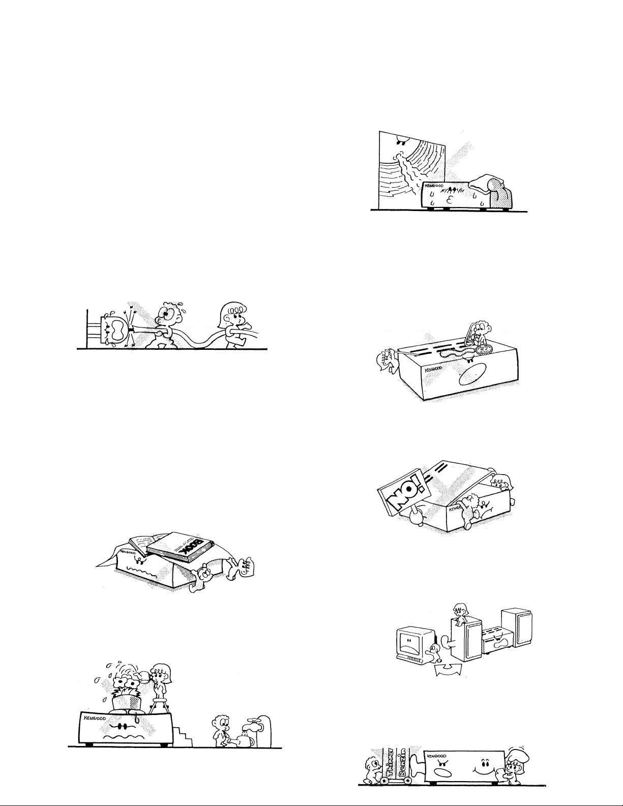
7. Heat — The unit should be situated away from
heat sources such as radiators, heat registers,
stoves, or other units (including amplifiers) that
produce heat.
8. Electric shock — Care should be taken so that ob
jects do not fall and liquid is not spilled into the en
closure through openings. If a metal object, such as
a hair pin or a needle, comes into contact with the
inside of this unit, a dangerous electric shock may
result. For families with children, never permit chil
dren to put anything, especially metal, inside this
unit.
4, Ventilation — The unit should be situated so that
its location or position does not interfere with its
proper ventilation.
To maintain good ventilation, do not put records or
a table-cloth on the unit. Place the unit at least
10 cm away from the walls,
Do not use the unit on a bed, sofa, rug or similar
surface that may block the ventilation openings.
5. Water and moisture — The unit should not be
used near water — for example, near a bathtub,
washbowl, kitchen sink, laundry tub, in a wet base
ment, or near a swimming pool, etc.
9p Enclosure removal — Never remove the en
closure. If the internal parts are touched accidentally,
a serious electric shock might occur.
10. Magnetic fields — Keep the unit away from
sources of magnetic fields such as TV sets, speaker
systems, radios, motorized toys or magnetized
objects.
11. Cleaning — Do not use volatile solvents such as
alcohol, paint thinner, gasoline, or benzine, etc. to
clean the cabinet. Use a clean dry cloth.
6. Temperature — The unit may not function pro
perly if used at extremely low, or freezing tempera
ti imq Thp. ìHppI pmhipnt tpmnpmtiim i.s ahovp. -I- B°C
Page 5
A\ Caution: Read this page carefully to ensure safe
atioop
oper-
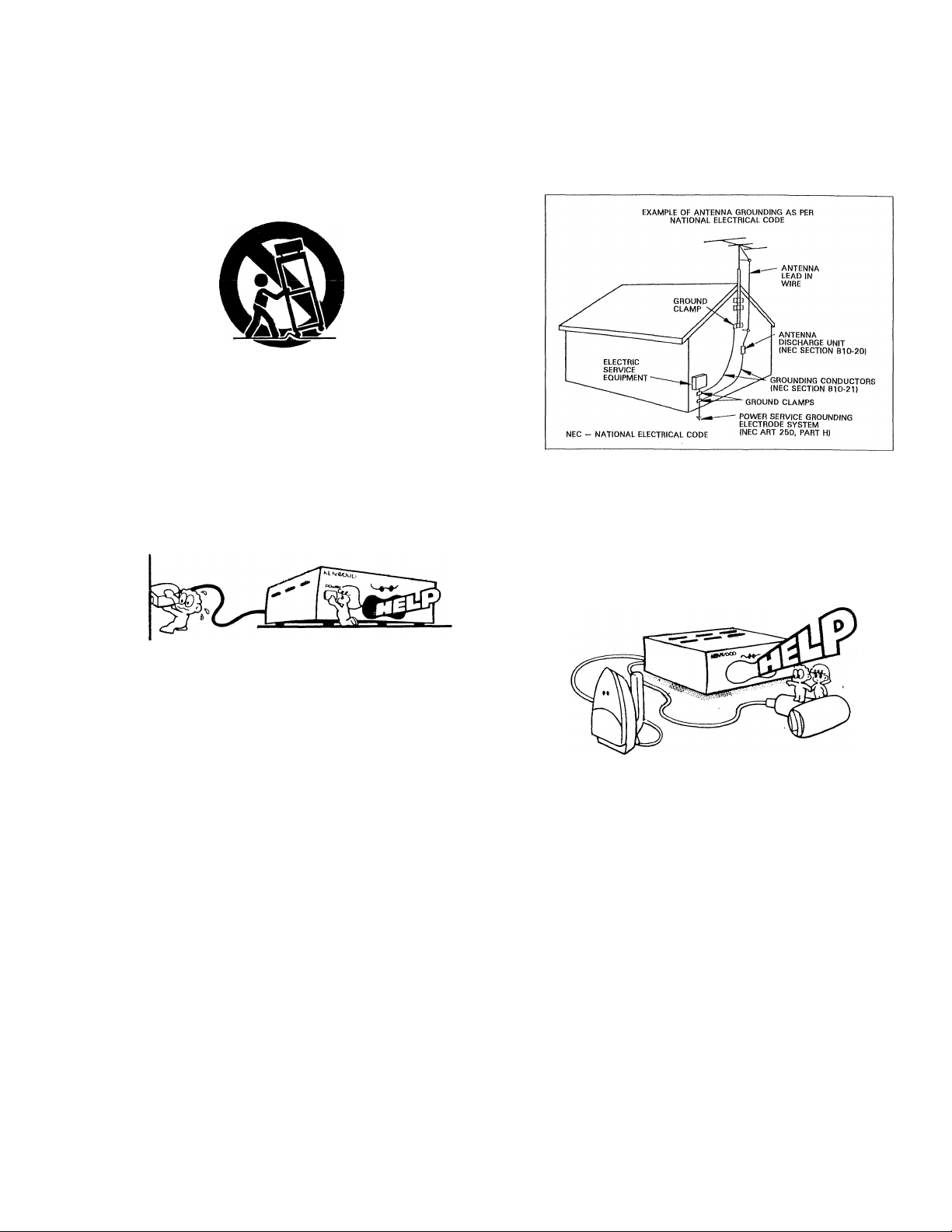
12, Carts and stands — An appliance and cart com-
binatibn should be moved with care. Quick stops,
excessive force, and uneven surfaces may cause the
appliance and cart combination to overturn.
13, Nonuse periods — The power cord of the unit
should be unplugged from the outlet when left un
used for a long period of time.
14, Abnormal smell — If an abnormal smell or smoke
is detected, immediately turn the power OFF and pull
out the power cord. Contact your dealer or nearest
service center,
POWER OFF!
ductors, location of antenna-discharge unit, connec
tion to grounding electrodes, and requirements for
the grounding electrode. See Figure.
18, Power lines — An outdoor antenna should be lo
cated away from power lines,
19, AG outlets — Do not connect other audio equip
ment with a power consumption larger than that
specified to the AC outlet on the rear panel. Never
connect other electrical units, such as an iron or
toaster, to it to prevent fire or electric shock.
15. Damage requiring service — The unit should be
serviced by qualified service personnel when:
Ap The power-supply cord or the plug has been
damaged; or
B. Objects have fallen, or liquid has been spilled into
the unit; or
C. The unit has been exposed to rain; or
D. The unit does not appear to operate normally or
exhibits a marked change in performance; or
E. The unit has been dropped, or the enclosure
damaged,
16. Servicing — The user should not attempt to ser
vice the unit beyond that described in the operating
instructions. All other servicing should be referred
to qualified service personnel.
17. Outdoor antenna grounding — If an outside an
tenna is connected to the receiver, be sure the an
tenna system is grounded so as to provide some
protection against voltage surges and built up static
charges. Section 810 of the National Electrical Code,
ANSI/ NFPA No. 70—1984, provides information
with respect to proper grounding of the mast and
supporting structure, grounding of the lead-in wire
to an antenna discharge unit, size of grounding con
The maximum capacities indicated for the AC out
lets on the rear panel of this unit are as follows.
SWITCHED outlets
:200 W
Notes:
---------
1. Item 3 is not required except for grounded or polarized equipment.
--------------------------------
-------------------
---------------------------------—
Page 6
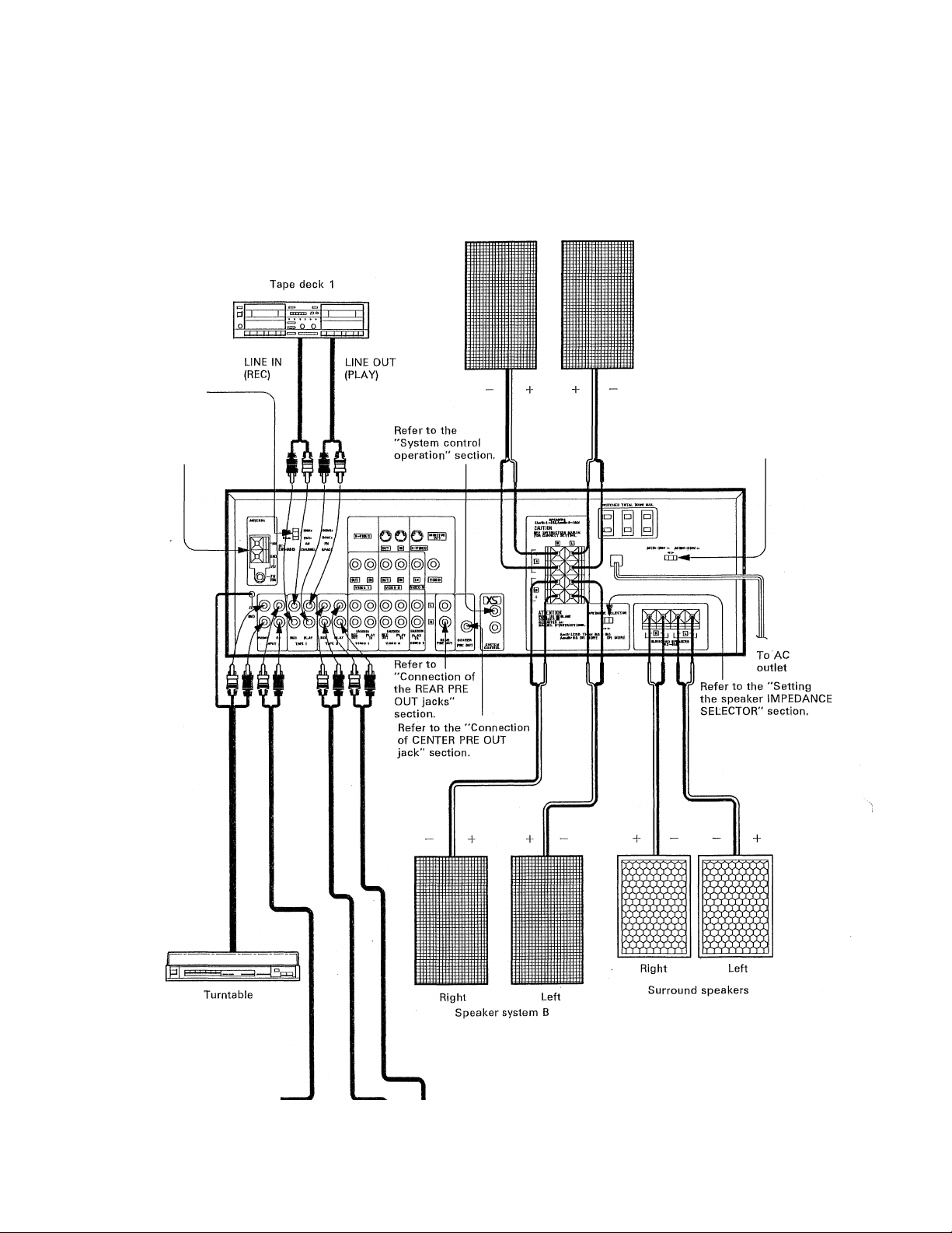
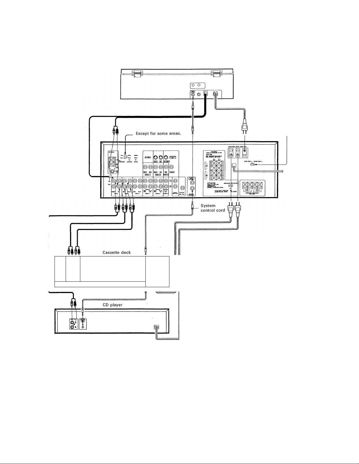
System connections
Make connections as shown in the diagram below. When connecting the related system
components, refer also to the instruction manuals of the related components.
Do not plug in the power lead until all connections are complete.
Connection of audio components
Speaker system A
Right Left
FM PE-EMPHASIS/
CHANNEL SPACE switch
(Except for some areas.)
Refer to the "Antenna
connections" section.
AC voltage
selector switch
(Except for some
areas,)
(Turntable using MM
cartridge)
CD player
LINE IN (REC)
Tape deck 2
LINE OUT
(PLAY)
Notes:
1. To prevent possible problems, always disconnect the power
plug or turn off the POWER key of the receiver before
connecting or disconnecting the cords.
2. When connecting the cords, always insert the pin plugs
securely into the connecting jacks.
• Insufficient insertion may result in no-sound or no- picture
problems or generation of noise.
Page 7
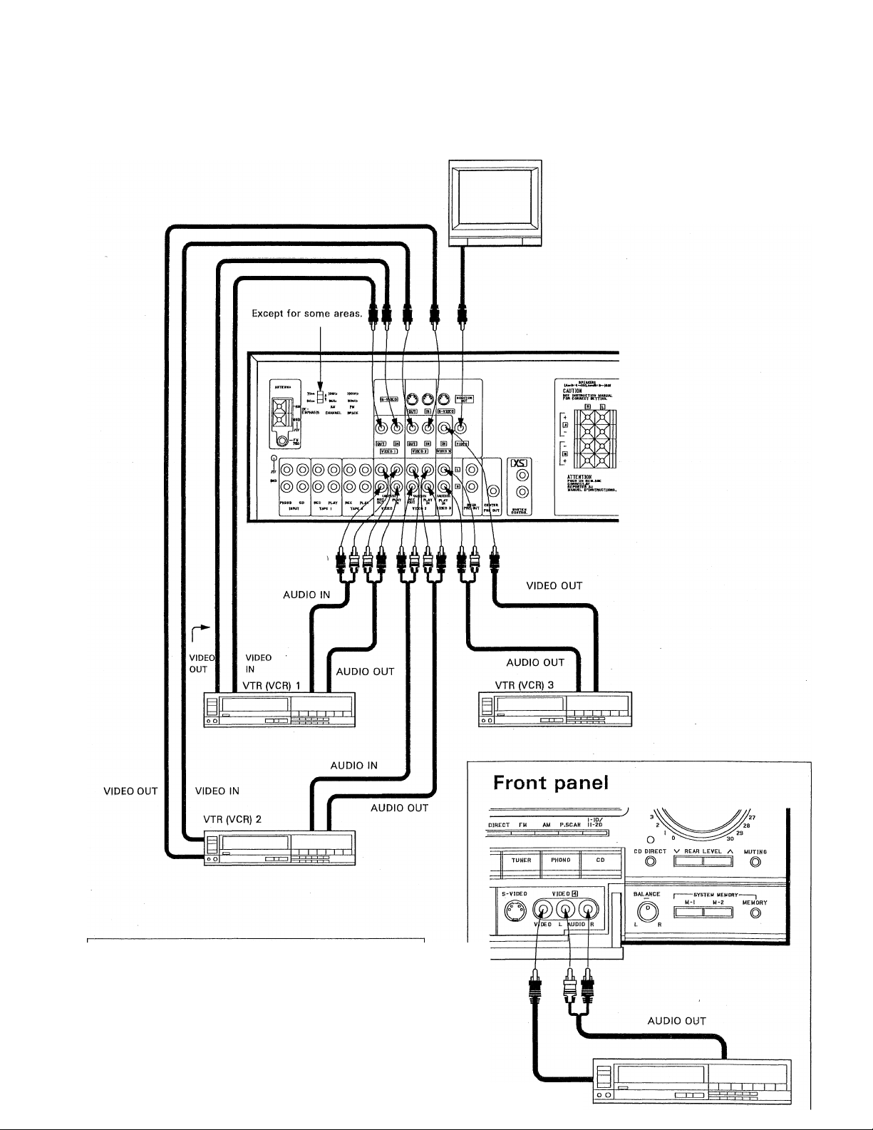
Connection of video components
TV monitor
(Refer to "Connection of TV monitor" on page 9)
S-VIDEO Jacks:
In the S-Video (Y/C separated) signal transnnission
system, the regular video signal (composite signal) is
separated into a signal identifying the brightness
(Y: luminance) and a signal identifying the color
(C: chroma) to be transmitted.
Use of these jacks provides improved picture quality.
When the S-VIDEO jacks are to be used, please read
carefully the caution on page 27.
VIDEO OUT
Page 8
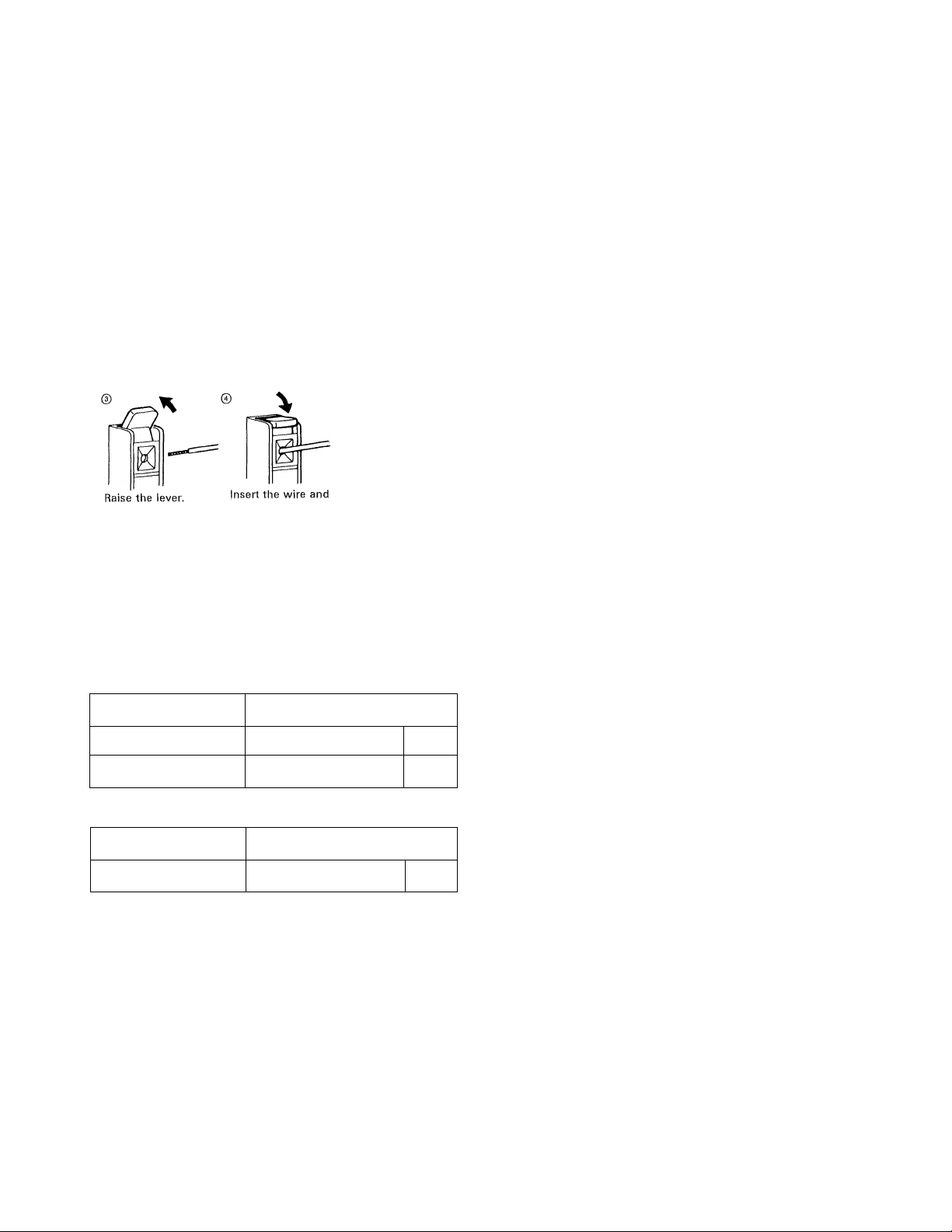
System connections
Speaker connections
10 mm
© ©
Remove insulation
from lead tip.
return the lever.
Speaker lead connection
Twist wire tightly
and solder.
©
The wire is
now locked.
WARNING!
Particular attention must be given to making good
electrical contact at the amplifier-output and speaker
terminals.
Poor or loose connections can cause sparking or
burning at the terminals because of the very high
power that the amplifier can deliver. Follow these steps
carefully.
■ Connecting the front speakers
Connect speakers rated at 4 ohm or more to the SPEAK
ERS terminals.
1, Connect the left speaker to the L speaker terminals on
the rear of the receiver and the right speaker to the R
terminals,
2. Connect each cable as shown in the illustration, taking
care that the wires do not make contact with other
terminals.
Notes:
---------—------------
1. Take care so as not to short the positive (+) and negative (—)
speaker cords.
If the left and right speakers, or positive and negative cables,
2.
are connected the wrong way, the reproduced sound may be
unclear, with ambiguous location of the musical instruments
etc. To avoid this, pay attention to the left and right and
positive and negative indications when connecting the speak
ers.
------—--------------------------
-------------------------
When using the speaker A or speaker B separately
Speaker impedance
4a, ea
sa, lea 8a OR MORE
When using the speakers A and B simultaneously
Speaker impedance Selector position
sa, 1 ea
A or B: LESS THAN 8a
A and B: 8a OR MORE
IMPEDANCE SELECTOR
Selector position
□
AorB^LESS THAN 80 80
AondB‘80 OR MORE OR MORE
D
□1
■ Setting the speaker IMPEDANCE SELEC
TOR
When connecting the speakers to the speaker terminais,
set the IMPEDANCE SELECTOR switch according to the
table on the left.
• When the IMPEDANCE SELECTOR switch is set to,
"80 OR MORE", it is impossible to use the A and B
speakers at the same time.
Therefore, when using the speakers A and B simulta
neously, be sure to set the IMPEDANCE SELECTOR
switch to the "A and B: 80 OR MORE" position.
Notes:
---------
------------------------------------------------
1. During speaker system connection and operation of the
speaker IMPEDANCE SELECTOR, set the POVv/ER key to OFF.
2. Check that the connected lead wires of the speaker systems
do not contact with other jacks or terminals.
------------
-------———
Page 9
Except for some areas
MONITOR OUT jack
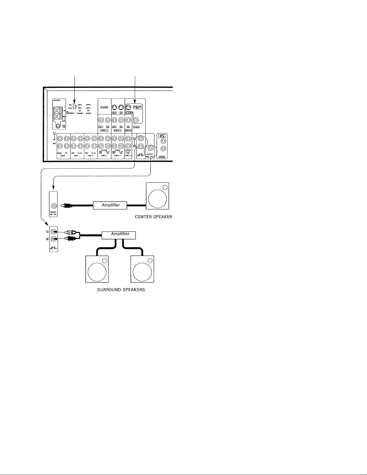
■ SURROUND SPEAKER terminals
Connect speakers having' an impedance of between 8
ohms and 1 6 ohms, and place them to the left and right
behind the listening position.
■ Connection of the REAR PRE OUT jacks
The Surround sound can be enjoyed sufficiently with the
built-in amplifier. However when more power is required
for Surround sound, use these jacks for an amplifier to
drive the Surround Speakers.
Connect these jacks to the AUX jacks, etc. of the amplifier
for Surround Speakers, using the audio connection cord.
■ Connection of CENTER PRE OUT jack
Use this jack when the Dolby Pro-Logic Surround function
is used. Connect to an AUX jack, etc. of your amplifier
using an audio connection cord,
■ Connection of TV monitor
Connect the MONITOR OUT jack on the rear panel of this
unit to the video input Jack of your monitor TV using a
video cord with RCA pin jacks.
When a TV monitor equipped with an S-VIDEO jack is
used, connect the S-VIDEO jack of this unit to the
S-VIDEO jack of the TV monitor using a special S-Video
connection cord.
Note:
-----------------------------------—-----------------------
A TV monitor can be connected to this unit via both the S-VIDEO
jack and the VIDEO jack. With some TV monitors, when the
S-VlDEO jack is used, the input signal to the TV monitor is
automatically switched to the S-Video input. Since on-screen
display is not possible if this occurs, disconnect the S-VIDEO jack
and only use the VIDEO input (composite input) when the
on-screen display is required,
When the signal is input via one of the unit's VIDEO input jacks,
no signal is output from the MONITOR OUT S-VIDEO jack.
------
——
-------
—-
■ AC outlets
The AC outlets on the rear panel may be used to supply
power to other components in the system, such as
turntables, tape decks, etc. Never connect equipment
whose power consumption exceeds the maximum value
shown at each outlet.
SWITCHED outlets:
These outlets supply power only when the unit is turned
on. The maximum total capacity is 200 watts.
■ Connection of VCRs
• S-VlDEO jacks are also available for connection of
VIDEO 2 inputs/outputs and VIDEO 4 inputs.
Page 10
System connections
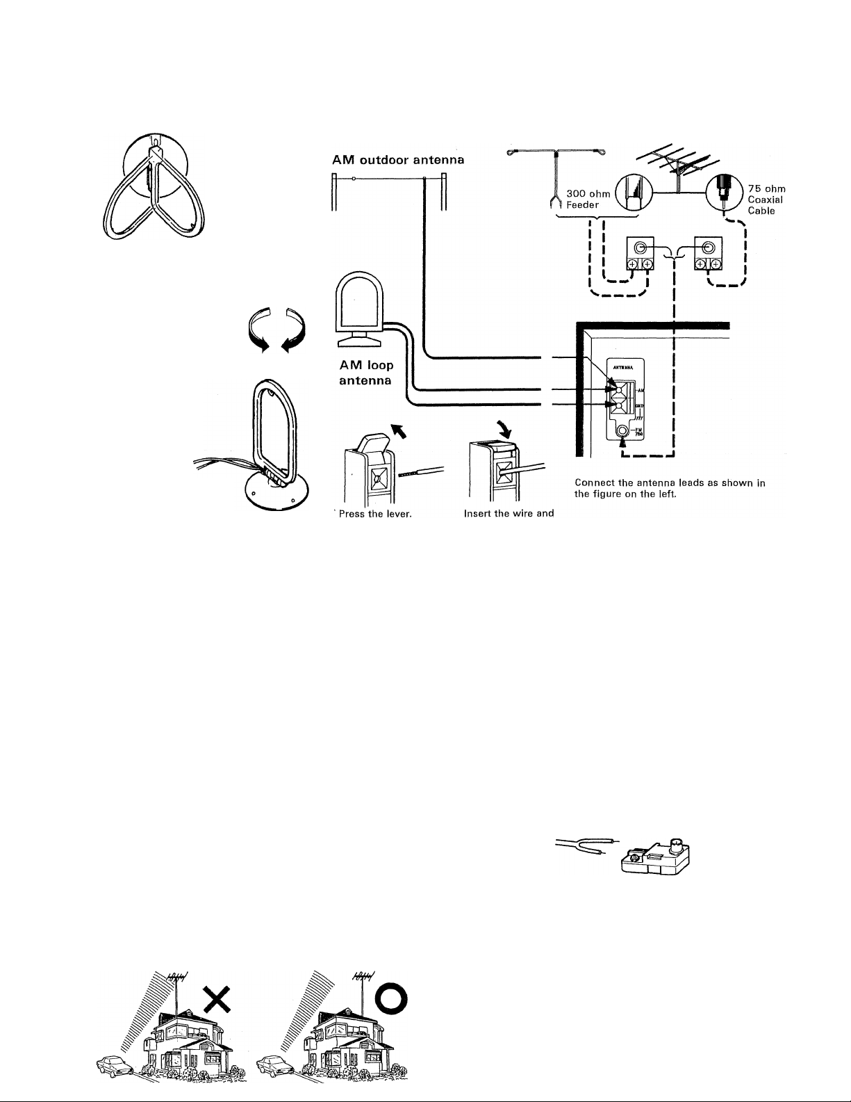
Antenna connections
Vary the direction of
the loop antenna.
AM loop antenna
Keep the speaker leads
and AC cord away from
the AM loop antenna,
FM indoor antenna FWI outdoor antenna
AM loop antenna holder
AM antennas
AM loop antenna
Attach the AM loop antenna to the supplied loop antenna
stand and place it on a shelf, etc., or install it on the rack
or wall with screws.
Rotate the AM loop antenna to the right or left for best
reception.
(Mote;
---------------------------------------------------------—-----
Do not place the AM loop antenna directly on the unit. As this
unit employs computing devices, placing the AM loop antenna on
the unit may result in noise generation. Place the AM loop
antenna away from the unit.
----
—
AM outdoor antenna
In steel buildings or at a great distance form the transmit
ter, it may be necessary to install an outside long wire
antenna,
The end of this wire should be stripped of insulation and
connected to the AM terminal. At this time, keep the loop
antenna connected.
return the lever.
FM antennas
FM indoor antenna
Connect the T-shaped indoor antenna (supplied) to the 75
ohm FM ANTENNA terminal with the 75 ohm/300 ohm
antenna adaptor as shown in the Antenna connections
diagram. Spread the two arms that form the top of the 'T''
horizontally and hold them against convenient wall sur
faces.
Try several locations for best results with your favorite,
stations. Tape the antenna in place where the best
compromise is found between listening results and ap
pearance.
Connection of the 75 ohm/300 ohm antenna adaptor
Indoor antenna feeder
Loosen the screws with a screwdriver. Insert the antenna feeder un
der the screw heads and tighten the screws firmly.
• To minimize auto-ignition noise, locate the antenna as
far from heavy traffic as possible.
• Keep the feeder or coaxial calbe as short as possible.
Do not bundle or roll up excess cable,
• The antenna should be at least two meters (6,6 feet)
from reinforced concrete walls or metal structures.
FM oiitrinor antenna settina
Page 11
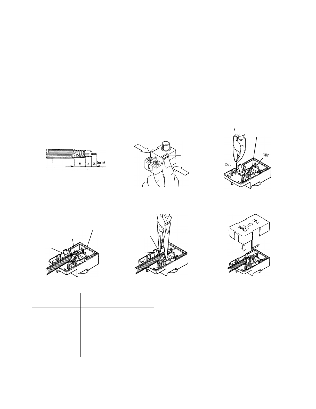
FM outdoor antenna
Be sure to use an outdoor FM antenna to receive good
sound quaiity FM broadcasts with a mininnum of noise.
When connecting an outdoor antenna to the antenna
terminals of this unit, use a 75 ohm/300 ohm antenna
adaptor connected to the coaxial cable as illustrated. The
75 ohm/300 ohm antenna adaptor is supplied with this
unit. Be sure to connect the coaxial cable to the adaptor
as instructed below. '
Note:
-------
An FM outdoor antenna can be connected to the receiver with
either a 75 ohm coaxial cable or a 300 ohm ribbon feeder. For
proper connection, carefully read the instruction manual pro
vided with outdoor antenna.
------------------—
■ 75 ohm coaxial cable connection (Follow the order of numbers.)
-----------------------------------------------
------
------
Arrange the coaxial cable as illus
trated.
©
Outer shield
(Braid)
RG-6 (5C-2V) or RG-59 (3C-2V)
Connect the processed coaxial ca
ble to 75 ohm/300 ohm antenna
©
adaptor as shown below.
Insert the inner conductor
into the slot on the clip.
Wire mesh
Outer shield
Inner
conductor
Open the 75 ohm/300 ohm an
tenna adaptor cover.
©
Press the claws in the direction of
the arrows with the fingers to re
lease the lock and pull out the cover.
Claw
Secure the holders A and B, Close the cover.
© Cut off the red wire and remove it
from the clip.
©
Holder B
Holder A
\V/ / R®eiove the
U// / red wire
Channel
Space Frq,
FM: 100 kHz
AM: 10 kHz
FM: 50 kHz
AM: 9 kHz
DE-EMPHASIS
1,
2.
Area
U.S.A.
Canada and
South Ameri
can
countries
Other
countries
FM DE.EMPHASIS/CHANNEL SPACE table
75ms
50ms
DEEMPHASIS
lOkHz
9kHz
AM
CHANNEL
lOOkHz
50kHz
FM
SPACE
FM
7 5 /AS
50 /AS
■ FM DE^EMPHASIS/CHANNEL SPACE
switch (Except for some areas.)
The FM DE-EMPHASIS/CHANNEL SPACE switch on the
rear panel is set to the correct setting that prevails in the
area to which the unit is shipped. Fjowever, if the FM
DE-EMPHASIS/CHANNEL SPACE setting is not matched
to the area where the unit is to be used (for instance, if you
move from area 1 to area 2 or vice versa), desired
reception of AM/FM broadcasts cannot be expected. In
this case, change the FM DE-EMPHASIS/CHANNEL
SPACE setting in accordance with the area corresponding
to the table on the left,
The FM DE-EMPHASIS setting is switched over at the
same time.
Note: ---------
When changing the setting of the FM DE-EMPHASIS/CHANNEL
SPACE switch, first disconnect the power cord, then reset the
channel space switch, connect the power cord again, and turn
the power on.
-----------
------—----------------------------------------
------
---------
-
Page 12
■ii
ii
ill
ill
l);j ^
i S'
System control operation
Connection
Using the system control cords provided with KENWOOD system component models, make connections as shown below.
Turntable
Except for some areas,
* For a cassette deck to
be subject to system
control operation, it
must be connected to
the TAPE 1 jacks.
——
pi
□ f
■ Connection of the audio cords and sys
tem control cord
Make sure that the audio cords are connected correctly
right and left as in the figure.
If the system control cord and audio cords are not
connected properly, the automatic system governing re
mote control and system functions will not operate.
(For connections of the audio cords, refer to the "System
connections" diagram.)
By connecting this unit to KENWOOD cassette deck, CD
player, and turntable models equipped with system con
trol jacks, the following integrated operation features
become available.
Operation
1, Automatic play operation
When starting play with the turntable, cassette deck, or
CD player connected to the receiver, press the desired
input selector keys on the receiver. The turntable,
cassette deck, or CD player will automatically enter
play mode.
In the same way, pressing the Play key of the turntable,
cassette deck, or CD player will automatically switch
the input selector on the receiver to the component on
which the Play key is pressed,
2, Synchro recording
To record the sound from the CD player or turntable
onto a tape with the cassette deck, press the CD or
PHONO of the input selector keys and load a CD or
record. Set the cassette deck to rec pause mode, then
press the PLAY (START) key of the CD player or
turntable. The cassette deck will start recording auto
matically. synchronized with the CD player or turntable
starting play.
3, Remote control
The remote control unit provided with this unit, to
which a KENWOOD system turntable, cassette deck, or
CD player is connected, is equipped with related
control keys. The related components can be con
trolled using these keys.
Mote: ----------------------------------------------------
During recording with a cassette deck, the input selector on the
receiver is fixed at the source from which the recording is made,
bv the .sv.stem control circuit. At thi.s time, nre.ssina anv of the
----------
------------------------
Page 13
Controls and indicators
Display section
THROUGH DUB. indicator
VIDEO MONITOR out indicator.
SP, [S [B] indicator
EQ, ON/DEFEAT indicator
EQ, REC indicator
—I EQ.REc I ra ibi gMgiiaiiÌTÌ i 4 e *-ii ^ AUTO I HsaasESB t-io'
TAPE 2 indicator
AUDIO INJECTION indicator
— AUTO indicator
/
------
TUNED indicator
MEMORY indicator
STEREO indicator
|5FW DEFEAT ^SP. ^VIPEO MONI. ^THROUGH DUB. AUDIO INJ. TUNED STEREO II-RO-
!,r
f/i'
t ¿7.
*ilji
KHz
MHz
SOD
Si-
Ei-
ii-
Graphic equalizer —
Spectrum analyzer.
(Peak hold) display
^ Input
Preset channel
Station name
Frequency
REAR level
CENTER level
AUDIO INJECTION ON/OFF
THROUGH DUBBING mode
SURROUND mode
CENTER mode
Graphic equalizer information
SYSTEM MEMORY
SPEAKER A/B. ON/OFF
V. DELAY TIME etc. J
Preset function indicator
REAR volume level
CENTER volume level -
indicator
display
Page 14
Controls and indicators
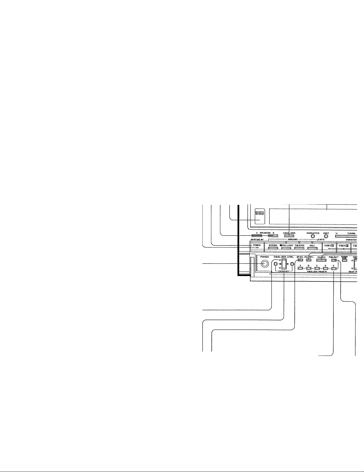
REMOTE SENSOR
Point the supplied remote control unit towards this sensor
and operate.
SPEAKERS A and B keys —
Selects the speaker system to be used for listening.
The speaker system being used is shown on the display.
_______
______
-----------
_______
---------------
__________
-----------
POWER key
Switches the power ON/STANDBY.
Power stand-by indicator
This indicator lights if the power cord is plugged into the
AC outlet. It is lit to show that the POWER key on the front
panel or the POWER key on the remote control unit can
be activated,
- EQUALIZER key
Press this key to ON and the frequency characteris
tics of the sound will be modified by the graphic
equalizer.
In the DEFEAT position, the frequency characteris
tics remain unchanged.
Display section
KBnIWOOD AUD]0-VIDEi|i stereo receiver K^i-VSOZO
n
PHONES jack
This jack accepts the standard stereo headphone plug.
When you wish to listen through headphones alone, set
the SPEAKERS keys (A and B) both to the OFF position.
---------------
---------------------------------
----------
EQUALIZER LEVEL control keys
Adjust these keys up and down to equalize the sound level
of the indicated frequencies with in a range of ±1 2 dB.
EQUALIZER FREQUENCY keys
These keys are used to select the equalizing frequency
among 60 FIz, 1 50 Hz, 400 Hz, 1 kHz, 2.4 kHz, 6 kHz, and
1 5 kHz.
Equalizer preset MEMO, key
This key is used to store an equalizer pattern the PGM
PRESET memory.
------------------
--------
---------------
----------------
---------------
.
EQUALIZER PRESETS (A - E) keys
Use these keys to store equalizer patterns in memory
or to recall them.
Equalizer preset mode key (PGM/SET)
Each time this key is pressed, the recall mode of the
equalizer preset patterns alternates between PGM
(user programmed patterns) and SET (factory preset
patterns.)
-------------------
Page 15

Page 16

Controls and indicators
DIGIT key
In the station name input mode, pressing this key ad
vances the column after a character is selected with the
TUNING/CHARACTER UP/DOWN ([AHY]) key. When
this operation is repeated four times the station name
input mode is automatically released.
TUNING/CHARACTER keys
Used to change the frequency. Pressing the UP (17^) side
will advance to a higher frequency and pressing the
DOWN ([y} side will nnove to a lower frequency.
In the station name input mode, this key is used to select
the characters.
---------------
------------
------
--------
CHARACTER key
Press this key to activate the station name input mode.
SURROUND keys
Press any of these keys to select the required SURROUND
mode. When the Surround sound is not required, press the
BYPASS key to set to the BYPASS mode,
DELAY TIME keys
With the SURROUND mode activated, select the required
delay time using these keys.
------------
---------------—
----------------------
This key is used to select the CENTER MODE for the
DOLBY PRO-LOGIC SURROUND mode. Each time
this key is pressed, the CENTER MODE changes in
the following order:
^ NORMAL—► WIDE-> PHANTOM-,
I
---------
-------
CENTER OFF —
CENTER LEVEL keys —
These keys are used to adjust the CENTER LEVEL in
the NORMAL or WIDE mode of DOLBY PRO^LOGIC
function. The output level of the center speaker can
be increased or decreased between -F20 dB and
—50 dB around the front speaker level,
----------------
---------
'
------
-----------------------
Page 17

AUTO key
Press this key to select the tuning nnode between
AUTO or MANUAL In MANUAL nnode, FM stereo
broadcasts are received in monaural.
MEMORY key
When this key is pressed, the MEMORY indicator
lights and the unit stands by for entry of a preset
station number.
Numeric {1 ~ 0/10) keys
Use these keys to:
1) input directly the digits of frequencies, or
2) store and recall fequencies in the preset channels.
DIRECT key
Used to tune to a station directly. Input the desired
frequency with the numeric keys after pressing the DI
RECT key,
Band selector (AM, FM) keys
Press to select the receiving band.
Preset function (1-10/11-20) key
Used to select the 1-1 0 or 1 1-20 preset channel setting.
In either FM or AM mode, 20 stations can be preset at
random as each setting C'1-10" or "1 1-20") can contain
10 preset stations. Indicator "1-10" lights when the
"1-1 0" setting is used, and indicator "11-20" lights when
the "11-20" setting is used.
VIDEO DUBBING keys
Press any of these keys when dubbing the video
program sourceregardless of the input source selected
by the input selector key.
AUDIO INJECTION key
Press this key ON when it is necessary to replace the
sound of VCR with that of an AUDIO source during
video dubbing.
PRESET SCAN key
Use this key for preset channel scanning.
When a frequency stored in the preset memory is being
received, pressing this key shifts reception to the next
frequency stored in the preset memory.
System MEMORY key
This key is used to store the current playing condition in
memory.
SYSTEM MEMORY channel keys (M-1/M-2)
Two memory groups can be used with the System Mem
ory feature.
Page 18

Operating instructions
POWER key
EQUALIZER control keys
EQUALIZER key
STAND BY mode of POWER key
When the power cord of this system is plugged into an
AC outlet, the STAND BY indicator lights up regardless
of the ON/OFF setting of the POWER key. This
indicates that a small amount of current is being
supplied to the unit to back up the memory contents.
This mode is referred to as the Stand By mode. While
the STAND BY indicator is lit, the power of the system
can be switched ON/OFF from the remote control unit, ■
To mute the sound temporarily
Press the MUTE key,
• The point indicator blinks, and the output is muted.
• When the MUTE key is pressed again, the muting is
canceled, the point indicator lights steadily and the
previous output level is resumed.
The mute mode can also be released by changing the
output level using the remote control unit.
• The point indicator also blinks (for approx, 4 seconds)
when the muting functions is engaged immediately
after the power is turned ON.
CD DIRECT indicator -
Input selector keys
Point indicator
BALANCE knob
VOLUME
CONTROL
knob
■ Basic operation
1. Press the POWER key to ON,
• The display lights and the unit becomes operative.
• Pressing the key again switches the power OFF.
2. Press one of the input selector keys to select the input
source to be played.
• If a System Control cord has been connected to the
selected source component, it starts play automati
cally due the Automatic Play operation feature.
• With the Automatic Play operation feature, when one
of the source components is started to be played, the
corresponding input selector is automatically
switched for the source.
• The selected input source is shown on the display.
3. If automatic play operation using the System Control
cords has not been set, start playing the source com
ponent selected.
4. Adjust the output level with the VOLUME CONTROL
knob.
• When one of the VOLUME CONTROL keys on the
remote control unit is pressed, the point indicator
blinks and the VOLUME CONTROL knob is rotated.
5. Adjust the balance of the left and right output levels
with the BALANCE knob.
6. Adjust the tone referring to the description in the
"Graphic equalizer" section.
• The graphic equalizer effect can be switched ON/
DEFEAT by pressing the EQUALIZER key.
Notes:
---------------------------------
1. The CD DIRECT key should usually be set to OFF (with the
indicator not lit).
2. When the TAPE-2 selector switch is set to ON, the input
source selected with the input selector keys cannot be heard
from the speakers. To listen to a source other than tape deck
2, be sure to set the TAPE-2 selector key to OFF,
------
—---------------
--------
--------
Page 19

■ Operations using CD DIRECT key
To enjoy more pure and high-quality sound of
Compact Discs:
1, Press the CD key
2, Press the CD DIRECT key.
VIDEOID TAPE 2
TAPE 1
(MONITOR)
3, Play the CD player.
• The CD DIRECT key is given priority over the setting
of the input selector keys.
• The graphic equalizer cannot be used while the CD
DIRECT key is ON.
•To cancel the CD DIRECT input, press the CD
DIRECT key again or press one of the input selector
keys (except CD and TAPE 2 keys). The input will be
switched to the source indicated on the display.
Note: —
----------------------------
When the CD DIRECT key is pressed in one of the Surround
modes (□□ PRO-LOGIC, THEATER or HALL SURROUND), the
unit enters the Bypass mode.
TUNER
---------
PHOND
---------
EP
------------------------------------
■ To record an input source
1. Select the source to be recorded with the input
selector keys.
2. Play the source,
3. Set tape deck 1 and/or tape deck 2 to record mode.
Note: ---------------------------------------------------------------------------
When a tape deck is connected to this unit with a System Control
cord, all of the input selector keys are disabled during recording
and do not function until recording is finished, This will prevent
the recording from being interrupted.
--------------
■ Tape dubbing
Tape recordings may be duplicated (dubbed) easily using
two tape decks connected to the TAPE 1 and 2 jacks.
For example:
(TAPE 1 to 2):
1. Connect two tape decks to the TAPE 1 and TAPE 2
jacks.
2. Press the TAPE 1 key,
3. Play back the recorded tape and adjust the recording
levels before starting tape dubbing.
(TAPE 2 to 1):
1. Press the TAPE 2 key,
2. Press a key other than TAPE 1 of the input selector
keys such as CD.
3. Play back the recorded tape and adjust the recording
levels before starting tape dubbing.
4. Do not press the TAPE 1 key during recording with
tape deck 1.
Note:
-------
---------------
Adjust recording levels on the deck that is making the copy using
that deck's operating controls.
--------
---------------
—-------------------------------------
Page 20

Listening to broadcasts
TUNING(/CHARACTER) keys
Band selector keys
To listen to radio broadcasts
1, Press the POWER key to ON,
2. Press the TUNER input selector key.
3. Press the AM or FM band selector key,
4, Tune in the desired broadcasting station according to
:i'l
||l
the instructions in the "Tuning methods'" section be
low.
• During tuning, sound is not heard because the muting
circuit is activated. The sound will be heard suddenly
as soon as a station is received,so be careful in
setting the sound volume level,
5. When the desired station is received, adjust the volume
with the VOLUME CONTROL knob.
, I
H
ilii
■ Tuning methods
Auto tuning
When the TUNING key is pressed, broadcast frequencies
are scanned automatically in the upward or downward
direction until a station is located and tuned in. The
stereo/monaural FM reception mode is set automatically
according to the station,
1. Press the AUTO key so that the AUTO indicator lights,
2. Press the UP {[A) or DOWN ([Vl) segment of the
TUNING key.
• Pressing the UP ([7\]) segment scans broadcast fre
quencies by varying the displayed frequencies in the
upward direction, and pressing the DOWN ([V])
segment scans by varying the frequencies in the
downward direction,
• When a broadcasting station is received, the fre
quency display freezes and indicates the frequency of
the received station.
3. If the received station is not the desired station, press
the same segment of the TUNING key again.
• Repeat this until the desired station is received.
Manual tuning
Stations with weak signal strength cannot be received by
auto tuning. In such cases, tune in the desired station by
manual tuning. The station will be received in monaural
mode (monaural mode is resistant to noise),
1. Press the AUTO key so that the AUTO indicator is off,
2. Press the UP (|7\|) or DOWN ([Vl) segment of the
TUNING key,
• Every time the TUNING key is pressed, the displayed
frequency varies by one step in the direction indi
cated by the pressed segment.
• Holding the TUNING key depressed varies the dis
played frequency continuously.
3. When the frequency of the desired station is tuned in,
release the TUNING key,
• Noise may be heard if the tuned frequency is not
precisely the same as the frequency of the station. In
such cases, press the UP ([A]) or DOWN ([V} seg
ment of the TUNING key to adjust the tuning pre
cisely.
Page 21

MEMORY key
. Numeric (1 — 0/10) keys
TU
NED Indicator
TU^
<ED BTERED ll-eo —
TO~i isiasi^ti’a
m
'"‘i n i
..........
i
Preset function indicator
/ j S i i; i i r t i
I
...
Preset channel
I I M L,
...
1 i
............
ly*
Direct tuning
This method allows the desired frequency to be entered
directly using the numeric keys, without using the TUN
ING key.
1, Press the DIRECT key.
2, Enter the frequency of the desired station with the
numeric keys.
• When all of the digits of the frequency have been
entered, the station is automatically received.
• If the entered frequency is not in the receivable
frequency range, message "CAN NOT TUNE" is
displayed for 5 seconds, and the last station received
is received again.
■ Preset tuning
By storing the frequencies of broadcasting stations in the
preset channels according to the instructions in the "To
preset station frequencies" section, any of the preset
stations can be received by one-touch operation.
1. Press the preset function key to select "1 -10" or
"11-20".
2. Press the numeric key corresponding to the preset
channel of the desired station.
• The display shows the frequency of that station, and
the station is received.
■ DiatTAL PELAY SURBOUNP SYSTEM VOLUME CONTROL
f—r
E 3 A E I
ll 1 1 1 1 ll
B
7 B a o/io
ll 1 1 1 I ll
mr DIRECT FU AM P.BCAK ll-?0
MEV
N
,3 MI6J6 „
/11 /
I 1
P,SCAN key
DIRECT key
Preset function
(1 ^ 10/1 1-20) key
■ Preset Scan
This function allows the preset stations stored in the
preset channels to be received in sequence for 5 seconds
each.
1. Press the P.SCAN key.
• The frequency of each preset station is received for 5
seconds in sequence. A preset channel in which no
station has been preset is skipped, and the scan
operation moves to the next preset channel.
2. To stop Preset Scan, press the P.SCAN key again, '
• The preset station being received when the key is
pressed is received continuously.
■ To preset station frequencies
1. Press the band selector key for the desired band (FM or
AM).
2. Tune in the desired station following the instructions in
the "Tuning methods" section,
3. Press the preset function key to select the 1-10 or
11-20 preset channel range,
4. Press the MEMORY key.
• The IMEMORYI indicator on the display lights.
5. Within 5 seconds after pressing the MEMORY key,
press the numeric key (1 to 0/1 0) corresponding to the
preset channel in which the frequency is to be stored.
• If a frequency has already been stored under the
selected preset channel, the previously-stored fre
quency will be replaced by the new frequency.
6. Preset all desired frequencies by repeating steps 1 to 5
above.
• When preset channels 1 to 1 0 have become full,
press the preset function (1 - 1 0/1 1 - 20) key again
to select the 11-20 range.
Page 22

Listening to broadcasts
This unit allows both the frequencies and the names of broadcasting stations to be preset,
When a station is recalled by preset tuning, the display shows both the frequency and the
name of the station. (S.N.P.S.)
:|;i !
:'mI| ;
' l/ih
Selection of display characters with the
TUNING/CHARACTER key
Every time the UP (I AI) segment of the TUNING/CHARACTER key Is
pressed, the displayed character is varied in the following order:
B —C...Z ... 0—
Blank
(Pressing the DOWN ([V} segment varies the displayed character in
the reverse order,) ^
.........
N
i ^
c;: i\/i
1 M
^
.........
! I 1
1 i l\ 1 i .....................................................................
\ /4 ! М2.............C
C j\/i
i 1 1
i;;;:: i\/i ì::::;ì i i...................................................i
I 1 1 ,„J. 1..........................................il
'9—,
TUNED STEREO
c::i I c: i
...J l !
...........................
TUNED STEREO
1..i Ì !
........
.....
' h
1„.TmHz
TUNED STEREO
1 AJ10 1 ^
. . . . . . .
r“'l
..........
.......
i
¡MHz
i
I MHz
■ To preset station names and frequencies
Example 1: To preset the 91.50 MHz EM broadcast
frequency and its station name "WNY" in
preset chanel number 2.
1. Tune to 91,50 MHz EM.
2, Press the CHARACTER key;
3. Press the TUNING/CHARACTER key to select "W".
4, Press the DIGIT key to set the character and move to
the next location.
5. Press the TUNING/CHARACTER key to select "N".
6. Press the DIGIT key.
7. Press the TUNING/CHARACTER key to select "Y”,
I 1 Гч 1 \/
i/M 1 M i
i 1 l\ i
l^ M i M 1 1
, i! О 1 С 1
1 1
1
3 Г,
....
i 1 1
TUNED ЗТдао
...........................
,.j I
.....................
TUNED STEREO
Cl i 1
....................1.........
i, ,„„i I
,i 1
.............
8. Since the fourth column should be left blank, press
the DIGIT key twice or press the CHARACTER key,
1
.......
1 MHZ
9, Press the MEMORY key,
10. Press numeric key "T' to select preset channel 2,
1
I MHz
Page 23

! ! i
....
I \/ O
jAi i i I i..:j
, A ^
i i U \/ \
JAij i j O
-----------
.......
i
-----
-
I i i I l\/l
Hi i li I
i
...
i I
........
i 1.:.. i M I
Preset channel Receiving band
c:::i \ n
i.J I I i“«*
I l\/l
U Mi
LJ 1 U“’'"
■ To change a preset station name
Example 2: To change the name of the 810 kHz AM
broadcasting station stored in preset channel
number 1 2 from ''WHY8" to ''WGY"
1. Recall preset channel number 12 with the preset
function key and numeric key "2” according to the
instructions in the "Preset tuning" section.
2. Press the CHARACTER key,
\ ^ /
............
I j \
...
i ¿/ o
i/\|j L I i
.........
-1——
------------------
I o
I I C
!/M Cl r.U.
----------
I I c ,
I'y i..J i .'....C
I I C N/
Lvi U j
1 1 1. M
LM i::i j
—T—-
j
----------------------
s ‘
1 .. i O L/i
1 l.„ i M i
C) L/i
i I ! I
iZ) L/i
i ll !
L.,1 b/i
MM
i..,J b/1
I j M
! ""‘i
O
11.
MM
LJ M' 1
LJ i i
.......
Ci j I I
i I I I „.LH-
i I {I I
u I 1 LH-
i i i
I..i i i
......
i 1 1
LJ i 1
......
11.1
i 1jkHi
1.1
3. Press the DIGIT key to move to the first character
location to be changed.
4. Press the TUNING/CHARACTER key to select "G".
5. Press the DIGIT key twice.
6. Press the TUNING/CHARACTER key to select a blank.
7. Press the DIGIT key or the CHARACTER key.
8. Press the MEMORY key.
9. Press numeric key "2" to select preset channel number
12.
Page 24

Graphic equalizer operation
This unit incorporates a high-performance 7-band stereo graphic equalizer. The graphic
equalizer is equipped with memory for storing equalizer patterns created by the user, as well
as for storing factory-preset patterns which can be recalled easily to provide equalizing
effects suitable for various types of music.
EQUALIZER key
EQ, SPI, key
EQ. REC key
I ''-'iji
ihijiir
EQUALIZER control keys
(Press the FREQUENCY keys ©, ©
to select the frequency to be equalized.]
@ key
60 150 400 1 2,4 6 15
Hz Hz Hz kHz“*^ kHz kHz kHz
Sequential change of equalizer frequency
(T) key
■ To listen music processed by the graphic
equalizer
1. Press the EQUALIZER key.
• The |0N EQ.I indicator lights,
2. Press the FREQUENCY © or @ key shown in the figure
on the left to select the required frequency to be
equalized.
• The frequency selected will appear in the display for
5 seconds,
• The indication on the graphic equalizer display
blinks.
• Each time the FREQUENCY ©or © key is pressed,
the frequency is changed sequentially as shown in
the table on the left,
3. Press the EQUALIZER LEVEL key ©shown in the figure
on the left to set to the required level for the selected
frequency.
• Pressing the EQUALIZER LEVEL A key increases the
level of the selected frequency in -P2 dB steps up to
+ 12 dB.
• Pressing the EQUALIZER LEVEL V key decreases the
level of the selected frequency in —2 dB steps up to
-12 dB.
4. Repeat the operation in steps 2 and 3 to set the
equalizer pattern as desired.
• it is also possible to select a preset equalizer pattern
by pressing one of the EQUALIZER PRESETS keys (A
~ E)
5. To defeat the equalizer effect, press the EQUALIZER
key again.
• The |EQ. defeat"! indicator lights.
_________
■ Equalizer recording
With this unit, sound processed by the graphic equalizer
can be recorded through the TAPE-1 output.
1. Press the EQ.REC key.
• The |EQ. REC] indicator lights.
2. Start recording on the TAPE 1 tape deck,
• When the EQ.REC key is pressed again, the
|EQ. RECl indicator goes off and normal (unproc
essed) sound is output.
Note:
Page 25

■ Preset equalizer memory and its applica
tions
Five equalizer patterns are permanently preset in the
memory of this unit for easy recalling at any time.
1. Press the PGM/SET key to SET.
•The "EQ, SET-D" indication appears in the display
for 5 seconds,
2. Press one of the EQUALIZER PRESETS keys (A -- E).
• The recalled equalizer pattern is displayed.
■ To switch the display contents
Spectrum analyzer display
Press the EQ./SPI, key to SPI.
The spectrum analyzer display shows the frequency level
distribution of the signal being played. The spectrum
analyzer display is useful to refer to when setting equalizer
patterns.
Characteristics of the "SET" preset patterns
A; For solid and punchy sound.
B: For effective reproduction of dynamic movie
sound,
C: For easy-listening background music.
D: For music sound reproduction with a live, "being-
there" feeling.
E: For realistically reproducing vocal music.
■ To store user-programmed equalizer pat
terns in memory
Up to five equalizer patterns created by the user can be
stored in memory for recalling at any time,
1. Set the desired pattern with the equalizer control keys,
2. Press the PGM/SET key to PGM.
• The "EQ, PGM-D" indication appears in the display
for 5 seconds,
3. Press the MEMQ. key.
• The [memory] indicator lights,
• The "EQ. PGM-л:/' indication appears in the display.
4. Within 5 seconds, press any of the EQUALIZER PRE
SETS keys A to E.
■ To recall user-programmed equalizer pat
terns from memory
1. Press the PGM/SET key to PGM,
• The "EQ. PGM-D" indication appears in the display
for 5 seconds.
2. Press one of the EQUALIZER PRESETS keys (A ~ E).
• The recalled equalizer pattern is displayed.
I One of characters A to E is displayed inside \
___________
Graphic equalizer display
Press the EQ./SPI. key to EQ.
The frequencies are divided into seven frequency bands,
and the level of each band can be set while observing the
shape of the equalizer pattern,
• Even when the spectrum analyzer display is selected,
the graphic equalizer is displayed for about 5 sec
onds in the following cases.
(?) When the POWER key is set to ON,
© When any of the equalizer control keys is pressed,
@ When the MEMORY key is pressed.
® When any of the A to E keys is pressed.
After about 5 seconds, the spectrum analyzer display is
resumed.
Page 26

Playing video sources
■ To play a video source
(For Surround playback, refer to "Surround effects" on
page 28,)
1. Press the POWER key to ON.
2. Switch on the power of the monitor TV connected to
. the MONITOR OUT jack.
3. Select the playback source with the input selector keys,
4. Play the video component.
5. The video is reproduced on the monitor TV, and the
audio is reproduced through the speakers,
■ Dubbing between two VCRs
Video dubbing can be performed while listening to any
desired source,
With this receiver, through dubbing from VCR 2, VCR 3 or
VCR 4 to VCR 1 is possible.
To dub through from VCR 2 (or VCR 3 or VCR 4)
toVCRI:
1. Press the VIDEO DUBBING |2 ► T1 (or |3 or
|4 ► 11) key.
•ThelTHRQUGH DUB. 2 ► 11
(or [THROUGH DUB, 3 ► 11
or [THROUGH DUB, 4 ► 11) indicator lights.
2. Set the VCR 1 to the recording mode.
3. Set the VCR 2 (or VCR 3 or VCR 4) to the playback
mode.
■ Audio injection
During video dubbing, the sound from the VCR can be
replaced with sound from any desired audio source
without affecting the picture.
In addition, the graphic equalizer effect can be applied to
the recorded audio source,
1. Press the AUDIO INJECTION key so that the
lAUDIO If^^ indicator lights.
2, Select the desired audio source for Audio injection
with the input selector keys,
3, When equalizer compensation is required when record
ing a desired audio source with audio injection ON,
press the EO. REC key.
• The |EO REC| indicator lights up.
• Set the equalizer controls as desired.
4. Operate each VCR for dubbing,
Note:
----------------------
The audio injection does not function during through dubbing
mode.
-----
———-— ------------—-------------------
To stop through dubbing or after dubbing is
finished;
Press the VIDEO DUBBING |OFF] key.
• When through dubbing is not required, be sure to set
to the OFF mode.
Note:
----------------------------------------------
The audio injection does not function during through dubbing
mode.
--------------------------
-------------
Page 27

Example of video dubbing operation
■ To record with VCR1
When audio injection is not required (Through
dubbing):
1. Press the required VIDEO DUBBING key (|2 ► 1 L
|3 ► i1or[4~^).
2. Set the VCR 1 to the recording mode.
3. Set the playback VCR (VCR 2, VCR 3 or VCR 4) to the
playback mode,
When audio injection is required:
1. Press the VIDEO DUBBING lOFFl key.
2. Select the playback VCR with the input selector keys.
3. Set the AUDIO INJECTION to ON,
4. Select the audio source to be injected using the input
selector keys.
5. Set the VCR 1 to the recording mode,
6. Play the required VCR and audio source component.
Note:
The rear panel video output jacks do not output a video signal in
the following cases;
Signal input
jack
S-VIDEO flNl jack
of "VIDEO 2"
VIDEO EN] jack
of each "VIDEO"
VIDEO OUT jacks
of each "VIDEO"
Jacks with no output
S-VIDEO |0UT|
jack of "VIDEO
2"
VIDEO jack of
"MONITOR OUT"
S-VIDEO jack of
"MONITOR OUT"
■ To record with VCR 2
1. Press the VIDEO DUBBING [OFFl key.
2. Select the playback VCR with the input selector.
(When Audio Injection is required)
(3) Set the AUDIO INJECTION to ON.
(4) Select the audio source used for audio injection
with the input selector,
3, Set the VCR 2 to the recording mode,
4, Start playing the playback VCR,
(When the audio injection is ON, also play the audio
source component,)
• Since the S-VIDEO and VIDEO circuits are independent of each
other, dubbing/playback fronn an S-VIDEO jack to a VIDEO jack
or from a VIDEO jack to an S-VIDEO jack is impossible.
However, dubbing/playback from the S-VIDEO jack of "VIDEO
4" to each VIDEO jack is possible.
The relationships between the various video terminals are
shown in the table on the left.
• When a video component or TV monitor having an S-VIDEO
jack is used, be sure to connect both the S-VIDEO jack and the
(composite) VIDEO jack to the S-VlDEO and VIDEO jacks of this
unit.
Page 28

Surround effects
The reason why the sound you experience in concert halls
or stadiums is so real and live is that the sound comes not
only from the front but also from the surroundings. To
reproduce such conditions as close as possible to reality,
this unit is equipped with three Surround modes
(□□ PRO-LOGIC, THEATER, HALL). In addition, three
Dolby PRO-LOGIC modes - NORMAL, WIDE, and
PHANTOM-are provided to enhance the sound directiv
ity and to provide the sound with a more surrounding,
powerful '"being-there" feeling.
Note on Dolby Surround
Video softwares marked with nnipoiBVBURBouMoi are encoded
with Dolby Surround information. This unit incorporates a
Dolby Pro Logic Surround decoder for recreating the
Dolby Stereo theatre experience in your home with Dolby
Surround-Encoded source material.
To obtain this effect, press the □□ PRO-LOGIC key to ON,
■ Surround modes
□□ PRO-LOGIC mode
The PRO-LOGIC mode is used when playing a source
encoded with Dolby Surround signals. (The following
modes can be selected by pressing the CENTER MODE
key repeatedly.)
NORMAL:
Select this mode when the signal output from the
CENTER OUT jack on the rear panel is reproduced
through a small center speaker. Low frequencies below
1 00 Hz in this signal are distributed to the left and right
front speakers, and frequencies above 100 Hz are
reproduced through the center speaker,
WIDE:
The entire signal output from the CENTER OUT jack on
the rear panel is sent to the center speaker, without the
low frequencies below 1 00 Hz being routed to the left
and right speakers as in case of the Normal mode.
Set to this mode if the speaker used as the center
speaker is the same type of speaker as those used for
the front left and right positions.
PHANTOM:
This mode allows the PRO-LOGIC effect to be enjoyed
even when a center speaker is not connected. In this
case, the center signal is distributed to the left and right
front speakers.
MANUFACTURED UNDER LICENSE FROM DOLBY
LABORATORIES LICENSING CORPORATION. ADDI
TIONALLY LICENSED UNDER ONE OR MORE OF THE
FOLLOWING PATENTS: U.S.NUMBERS 3,632,886,
3,746,792 AND 3,959,590: CANADIAN NUMBERS
1,004,603 AND 1,037,877, ^'DOLBY" AND THE
DOUBLE-D SYMBOL□□ ARE TRADEMARKS OF
DOLBY LABORATORIES LICENSING CORPORATION,
THEATER Surround mode
This mode provides a three-dimensional effect similar to
that of a movie theater, V\/ith this mode, you can enjoy a
Surround sound effect similar to Dolby Surround sound
even when playing a video program which is not encoded
with the Dolby Surround system.
HALL Surround mode
This mode provides a natural reverberation effect. When
used with a normal source, you can enjoy the being-there
feeling or "presence" as in the hall.
Page 29

CENTER MODE
key
BYPASS key
How to make adjustments for the Dolby Pro-Logic mode
■ INPUT BALANCE adjustment
With this unit the INPUT BALANCE is adjusted automat
ically,
• 'This unit features an automatic input balance control,
eliminating the need to adjust L/R input balance for
different sources and optimizing performance of the
Dolby Pro Logic Surround decoding by minimizing
crosstalk/'
TEST TONE
ON/OFF key
TEST TONE
MODE key
CENTER LEVEL ,
keys
REAR LEVEL keys .
□□ iZD “
[ZD m □
o«en
DELAY TIME
[^ r^~i
CENTER LEVEL
[yn
REAR LEVEL CONTROL
5
VOLUME
MUTE
Remote control
DELAY TIME
keys
■ Surround Level adjustment
NORMAL/WIDE
1. Select "NORMAL" or "WIDE" with the CENTER
MODE key,
2. Press, the TEST TONE ON/OFF key on the remote
control at the listening position.
• Test noise will be heard,
3. Press the TEST TONE MODE key on the remote
control.
• Each time the key is pressed, the tone will be heard
from one of four positions in the following order:
LEFT
CENTER
4. Adjust the CENTER LEVEL and REAR LEVEL keys so
that the output volumes from the five speakers are
almost identical when listened from the listening posi
tion,
5. Press the TEST TONE ON/OFF key to OFF. '
PHANTOM
1. Select "PHANTOM" with the CENTER MODE key.
2. Press the TEST TONE ON/OFF key on the remote
control at the listening position.
• Test noise will be heard.
3. Press the TEST TONE MODE key on the remote
control,
• Each time the key is pressed, the tone will be heard in
one of three positions in the following order:
RIGHT
REAR
LEFT
RIGHT
REAR
4. Adjust the REAR LEVEL keys so that the output
volumes from the four speakers are almost identical
when listened from the listening position.
5. Press the TEST TONE ON/OFF key to OFF.
Page 30

HflP
'i'ir
Surround effects
■ THEATER SURROUND, HALL SUR^
ROUND adjustment
1, Press the THEATER or HALL Surround key,
2, Adjust the rear speaker output level with the REAR
LEVEL control keys.
• The REAR LEVEL control range is from +20 dB to
— 50 dB of the front speaker level.
■ Delay time adjustment
The output signal from the rear speakers is delayed
slightly than that of front speakers for each Surround
mode separately. The delay time can be adjusted as
desired separately for the □□ PRO LOGIC and THEATER
SURROUND modes. The delay time of the HALL SUR
ROUND mode is fixed at 30 ms and cannot be adjusted,
1. Press theDD PRO LOGIC or THEATER key.
2, Adjust the delay time using the DELAY TIME keys.
• For the □□ PRO LOGIC mode, the delay time can be
adjusted between 1 5 ms and 30 ms in 1.5 ms steps.
• For the THEATER SURROUND mode, the delay time
can be adjusted between 0 ms and 30 ms in 1.5 ms
steps,
■ To play sound with the Surround effect
1. Set the SURROUND key to ON,
• The selected Surround mode indicator lights,
2. Select the source to be played with the surround sound
effect, and play it.
3. Adjust the volume level,
• The VOLUME CONTROL allows you to increase or
decrease the volume level of all of the front, rear and
center channels simultaneously.
Note;
----------------------------------------------------------------
When this unit is in DOLBY PRO LOGIC SURROUND mode, the
graphic equalizer will operate only In '"SET" mode. Otherwise,
graphic equalizer operation will be canceled by the "'DEFEAT"
function. Therefore, when it is desired to use the graphic
equalizer when the unit is in DOLBY PRO LOGIC SURROUND
mode, press the PGM/SET key to set to "SET" mode.
—---------
■ To release the Surround mode
Press the BYPASS key.
• Be sure to set the BYPASS mode when the Surround
effect is not required.
BYPASS nnpRO-LOGlC THEATER
HALL
BYPASS key
Page 31

Standard arrangement
■ Arranging the speakers
A variety of rear speaker arrangement patterns are possi
ble according to room size, reverberation characteristics,
etc.
The arrangement pattern given here is typical example for
effective Surround sensation, The given example is only
suggestion. Arrange the speakers according to your indi
vidual taste.
Page 32

System memory
The required playback condition can be stored in memory
for each music source (tape, compact disc, phonograph
record (disc), or broadcasting program), so that the same
balance (between front and rear channels) and the same
equalizer pattern, etc. can be recalled at any time in
stantly.
Two types of settings can be stored in memory, and by
pressing the appropriate SYSTEM MEMORY (M-1 or M-2)
key you can recall the preset sound field condition
instantly.
Stored contents:
The stored contents in the System Memory are as follows:
• Input source (CD, PHONO, TUNER, TAPE, VIDEO, etc.)
(including TAPE 2)
• Preset channel in the TUNER position
• Audio injection
• EOUALIZER key setting (ON/DEFEAT)
• EQ. REC key setting (ON/OFF)
• Preset channel of the equalizer pattern
• SURROUND setting (ON/OFF)
• SURROUND mode
• Center mode
• Center level
• Delay time
• Rear level
• Video monitor out
• SPEAKERS A, B
• CD DIRECT ON/OFF
■ How to preset the System Memory
1. Set the playback conditions as desired.
• When selecting the tuner or equalizer, be sure to
designate the preset channel.
2. Press the SYSTEM MEMORY key.
• The ¡MEMORY] indicator lights and the '"SYSTEM
MEMORY indication appears in the display (for 5
seconds).
• If the "CAN NOT MEMORIZE" indication is dis
played, the tuner frequency or equalizer pattern will
not be preset in memory,
After presetting the playback condition for each
channel, press the MEMORY key again,
Note: —------------------------------------------------------------------------------------
If the contents of a preset channel is changed after being
designated as the tuner or equalizer section channel for System
Memory, the contents of the System Memory channel will also be
changed.
■ How to recall System Memory
1, Press the M-1 or M-2 key.
• The display shows "SYSTEM MEMORY 1" or
"SYSTEM MEMORY 2" for about 2 second, and the
settings of each section are changed to the preset
contents.
2, Readjust the setting of each section as required.
• When PHONO is selected as the input source, with a
system-controlled turntable connected, the turntable
will automatically start playing by recalling the Sys
tem Memory, Therefore, be sure to set a record on
the platter of the turntable before activating the
System Memory function,
• In the same way, when a system-controlled tape deck
or CD player is connected to this unit, the tape deck
or CD player can be started automatically by activat
ing the System Memory function.
Page 33

On-screen display
With this function, a connprehensive character display appears on the monitor screen every time an input selector key, etc.
is pressed.
There are six screen display patterns,
Each time the MENU ON SCREEN key on the remote control is pressed, the screen pattern is changed in the following
order:
__
Screen 1
(AUDIO)
-Screen 6 (ON SCREEN OFF)
Screen 2 .
(VIDEO)
Screen 3
(SURROUND)
Screen 5 (ON SCREEN STANDBY)
Screen A
(TUNER PRESET)
When one of the first four screens (Screen 1 to Screen 4) is displayed, it will be maintained until a key corresponding to
the screen menu is pressed,
With Screen 5, when a relevant key is pressed, the screen corresponding to the key will appear for 5 seconds and then go
out.
With Screen 6, there is no display on the monitor screen,
1. SCREEN 1 (AUDIO):
• Displays each setting of the various audio sources.
Displays the tuner station name, preset channel, receiving
band, and receiving frequency only when TUNER is
selected.
Displays the REC mode for TAPE 1.
Displays the REC mode for TAPE 2,
Displayed only when activated,
Displays the MONITOR output.
2. SCREEN 2 (VIDEO):
• Displays each setting of the various video sources.
Displayed when AUDIO INJECTION is activated.
(THROUGH DUBBING is also displayed when engaged)
Displayed only when EQ REC is activated.
3. SCREEN 3 (SURROUND):
• Displays each setting related to Surround sound.
Displayed only when Dolby Pro-Logic is selected.
Displayed only when Dolby Pro-Logic ''NORMAL" or
"WIDE" is selected.
Page 34

On-screen display
*
1 K 1
1K
- - - -
2
_ _ _
-
3
_ ^ ^
-
4
_ _ -
-
5
6
^
7
TUNER PRESET * *
8 K 1
9 - 1 0 - 1 1 W H Y Z
1 2 - 1 3 - 1 4 - -
S S
- -
^ -
^ -
- “
1 5 K L M N
16----------------17
----------------18----------------19-----------------
2 0
--------------
SCREEN 4 (TUNER PRESET):
• Displays the contents of the tuner preset channels.
SCREEN 5 (ON SCREEN STANDBY):
• Shows the standby mode for the on-screen display.
The screen shown in the figure appears for 5 sec
onds. then goes out.
• In this mode, when a relevant key is pressed, the
corresponding screen will be displayed for 5 sec
onds, then go out,
3. SCREEN 6 (ON SCREEN OFF)
• Shows that the on-screen display is turned OFF.
When the power is switched ON, the figure shown on
the left will be displayed from 5 seconds, then go out.
• There is no on-screen display in this mode.
• Set to this mode when noise interferes with the video
picture.
** TEST TONE **
C E N T E
LEFT %% RIGHT
%%
%% REAR
CENTER LEVEL
REAR LEVEL
Note:
---------
---------------------------------------------------------------------------------------------------------------------------- ----------------------------
R
W//.
+ 8 D B
+ 1 2 D B
4, TEST TONE DISPLAY
• This screen appears when the TEST TONE mode is
engaged. The “ (darkened cursor) blinks at the
position where the test tone is being output.
The position of the on-screen display (on the TV screen) may vary depending on the video software being played.
Page 35

Remote control operation
Loading batteries into the remote control unit
Remove'the battery cover,
While gently pressing the battery cover located on the
rear of the remote control unit slide it in the direction
of the arrow,
2. Insert the provided batteries. Take care to respect the
battery polarity (-f, —).
\ _____
R®
Ho
H ©
He
I o
( )l
©W
©9
©1
e6jI
^ j
■ Operations
1. Connect the power plug of the receiver to an AC
outlet,
• The receiver enters the power standby mode and the
power standby indicator lights.
2. Press the POWER key of the remote control unit or the
POWER key of the receiver.
• The receiver enters the power ON mode.
3. The various functions of the receiver can be operated
with the keys of the remote control unit.
Note for remote control operation
After pressing one of the operation keys, when the next
operation is required, press the next operation key firmly after
an approx. 1 second interval.
If the next operation key is pressed immediately after the
previous key, misoperation may result,
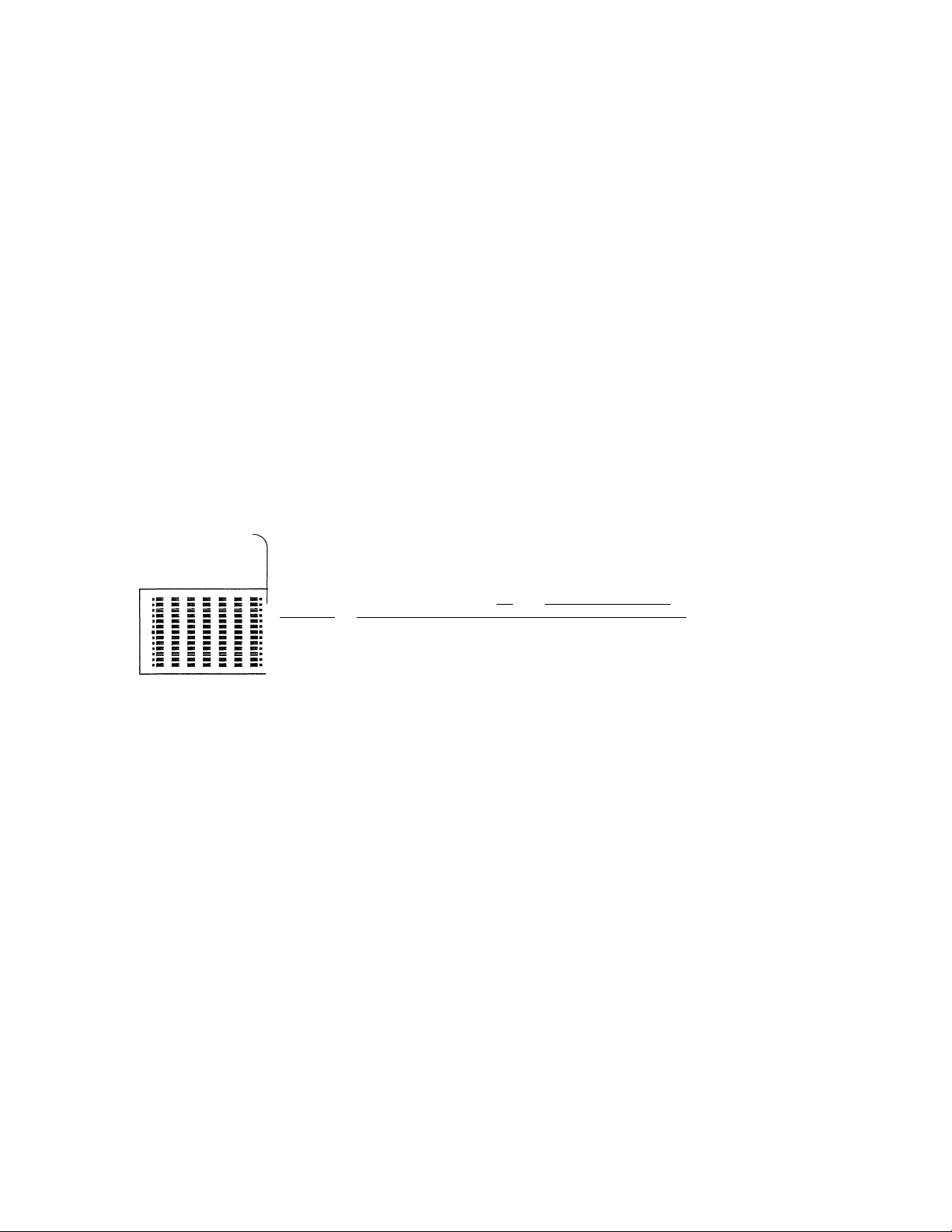
■ Operating range of the remote control
unit
The operating range of the remote control unit may differ
according to temperature, humidity, or using conditions,
however, it is defined approximately as shown in the
figure below:
For controlling the receiver, TV and VCR
Remote control sensor of the
receiver, TV or VCR,
3, Be sure to close the cover after inserting.
control operations, Their service life may be short,
Battery replacement
If the TRANSMIT indicator wii! not light up when an
operation key is pressed, the batteries may be ex
hausted, In this case, replace them with new batteries,
It is recommended to use alkaline batteries (LR03 or
AM-4 type) with long life.
The programmed contents are not immediately lost
when the batteries are removed for replacement. How
ever, they could be lost if the unit is left without
batteries for more than 3 minutes. In such a case, the
programming should be performed again. The function
signals of the non-learning, or fixed, keys are not lost
even in this case.
Note: ------------------------------------------------------------------------------
Avoid using old and new batteries together, as this may
corrosion.
cause
The signal transmission system
used by this remote control unit
is the infrared control system.
Note: -----------------------------------------------------------------------------------------
Malfunction may occur in case direct sunlight or the light of a
high - frequency lighting fluorescent lamp enters the remote
control light recepter. In such a case, change the installation
position of the unit so that the malfunction does not occur.
Page 36

Remote control operation
The remote control unit (RC-120) is capable of the remote control of this unit as well as other
KENWOOD system components connected to this unit via system control cords,
*KENWOOD VCR and *TV. In addition, it is also possible to program the remote-controllable
functions of other A/V components in the memory of RC-120, making it a multi-purpose
remote controller for the whole of your system.
Names and operation of controls
LEARN indicator
LEARN/USE selectswitch
Set to the USE position
for normal operation.
CD/VDP keys
TV keys
SYSTEM MEMORY keys
Input select keys
POWER keys
----------------------------------
LEARN ,, USE
----
FFin
B3 CQ m Q cm
^ [s [■□ im cm
ex:
cm m m im m
cm m ¡33 133 cm
TV/VIDEO
---------
[33 cm cm cm cm
• I3Ó/II-20
SYSTEM MEMORY I
l~in 1313 [33 rxi ri3
CD EQ.
□ 133
PHONO VIDEO I
33 CZ3
TUNER VIDEO Z
33 im
TAPE I VIDEO 3
cm cm
TAPE 2 VIDEO -1
cm mi
S 1^
AUDIO TV VIDEO
UNIVERSAL PROGRAMMABLE
TRANSM IT
um-
lAPt/VlUtU A> mB
VIDEO CH.
TV CHÌL ---------------TV VOL
ksCAf
I FM I I AM I
________
TOONO
I A/B I
FESM" ■ M^f ^№Àss'
m m m m m m
(AUXl
DELAY TIME
cm
CENTER LEVEL
i^n rm
REAR LEVEL CONTROL
POWER
KENWOOD
REMOTE CONTROL UNIT
RC-120
TV/VIDEO
cm
133-
-------
____
VOLUME
TRANSMIT indicator
Blinks when a remote control
signal is transmitted.
Mode switch
TAPE/VIDEO keys
Free key
Numeric keys
TUNER keys
PHONO keys
SURROUND keys
VOLUME CONTROL keys
^IMPORTANT:
This option may not be available in
some areas. For details on options,
consult your dealer.
■ Remote control operation
1. The whole of the keys can be used in three ways (three sides) by selecting the mode switch position. The AUDIO and
VIDEO sides contains the initial programming of KENWOOD-original remote-control codes, (Please refer to '"Original
functions of keys",)
• AUDIO position:
AUD]o'^j°^°AUX
• VIDEO position:
, am
Mode switch
• AUX position:
2. The remote control functions of other A/V components can also be programmed under the keys on the AUDIO and
\/inFn ciriiQc Qc \A/oii Qo nn thp Al lY oiHo Mo\A/Q\/csr \A/hon pn\/ infnrmptinn ici nrnnrfimmRrj Under a kev nn the AUDIO or
For the remote control of KENWOOD system components and KENWOOD TV.
For the remote control of KENWOOD VCR, KENWOOD TV and part of
KENWOOD system components.
All keys are available, that is, able to store the programming of other remote
control functions.
Page 37

Original functions of keys
LEARN/USE select switch
Set to the USE position.
Caution in Remote Control
• If the CD player is not equipped with the System
Control jack, it cannot be operated properly from this
remote control unit. In such a case, please use the
remote control unit provided with the CD player,
• If any of the following KENWOOD component mod
els is used, this remote control unit cannot be used to
control the CD manual search function or to make
entries with the numeric keys (1 to 0 and -f1 0):
DP-M97, DP-57, DP-47
LEARhI^J] ^aTRAWSMlT
,RN . . USE AUDlo\‘'^°AUK
□no CUED
_______
TAP£/V)DEO
rwi C3D
CD/VDP
Bivii] fHMil [FRI [Disci
n~l [FFH rTii~|
_
Tv/vweo
I
---
[ZD
1
nU QD dJ DO DO
DO rr~| [~B~| [~fl~] r~5~i
TV/VIDEO
I I rvn
CO DO [O CO
H
DO [Q [OilIQ] to
dD DID
PHONO VIDEO 1
DZl 1 1
TUNER VICEO 2
DU DZ]
TAPE 1 VIDEO 3
DID DID
TAPE 2 VIDEO A
1
---
S S
AUDIO TV VIDEO
-----------
..liWtRo FiSTO
SYSTEM MEMORY ll PHOHT
CD ED.
DU DZ] DID
1—1 1 1 1—1
DELAY TIME
CENTER LEVEL
REAR LEVEL CONTROL
1 1
---
1
POWER
MUTE
CZD
TV CH-^ -TV VOL^—
dMeh
.¿lb.
VOLUME
KENWOOD
Mode switch
Set to the AUDIO
or VIDEO
TAPE deck control keys
(Mode switch: AUDIO)
Use the A/B select switch to specify the A deck or B deck
of a dual-transport cassette deck.
The darkened keys (marked do not function at
this time.
(Mote: --------------------------------------------------—
\A/hen it is necessary to press the fast forward key after the
rewind key, be sure to press the stop key before pressing the fast
forward key.
--------
---------
---------------
VIDEO deck control keys (Mode switch: VIDEO)
TAPE/VIDEO
□FU nei [
\*^\ IBM
The darkened keys (marked do not function at
this time.
When remotely controlling the KV-D957S from KEN
WOOD (for U.S.A, and military), set the A/B select switch
to A.
VIDEO CH keys:
Pressing the key shifts the channel tuned on the VIDEO
deck upward, and pressing the key shifts it downward.
TV/VIDEO key:
Every time this key is pressed, the output from the video
deck is switched between the TV channel RF output and
video output.
Am mB
nm
VIDEO CH.
^11^1
TV/VIDEO
Page 38

Remote control operation
CD player control keys
►/II
CD/VDP
DISC
I I
Mode switch: AUDIO
These keys allow the same operations as the keys with the
same names on the CD player.
The DISC key is for use exclusively with a multiple CD
player. Pressing the DISC key allows one of DISC 1 to
DISC 6 to be selected in the following cycle.
DISC
1
Numeric keys (1 to 0)
^(6)-
TUNER control keys
1 1
DIRECT H0/IF20
TUNER
kstAN
Mode switch: AUDIO or VIDEO
These keys allow the same operations as the keys with the
same names on the receiver.
1 FM 1 1 AM 1
■ Turntable (PHONO) control keys
Mode switch: AUDIO or VIDEO
The Play (◄) and Stop (■) keys are provided,
■ System memory keys
SYSTEM MEMORY
М2 I
Ml
Mode switch: AUDIO
When the CD or TUNER input selector key is selected,
these keys can be used in place'of the numeric keys on the
CD player or receiver, respectively.
Mode switch; VIDEO
The numeric keys can be used in place of the TV channel
select keys,
■ TV set control keys
ТГ
-TV CH-
Mode switch: AUDIO or VIDEO
TV VOL keys:
Pressing the key increases the volume of the TV set,
and pressing the key decreases it.
TV CH keys:
Pressing the [A] key shifts the channel tuned on the TV set
upward, and pressing the key shifts it downward,
TV/VIDEO key:
Every time this key is pressed, the input to the TV set is
switched between the TV signal and the external video
signal.
-TV VOL-
Mode switch: AUDIO or VIDEO
These keys allow the same operations as the keys with the
same names on the receiver.
Equalizer key
EQ. key
Mode switch: AUDIO or VIDEO
Every time the EQ key is pressed, the equalizer of this unit
can be switched ON/DEFEAT or ten preset equalizer
patterns can be changed over in the following cycle,
PGM В
DEFEAT
L_
“PGM A-
SET E SET
• When DOLBY PRO LOGIC SURROUND is ON,
patterns will not be selected.
•PGM E^
SETA-
Page 39

Input selector keys
CD
r~i
PHONO
VIDEO 1
1 1
i 1
TUNER
1
---------
TAPE 1
1 1
TAPE 2
1 1
(AUX)
VIDEO 2
1
1 1
VIDEO 3
1 1
VIDEO 4
1 1
Mode switch: AUDIO or VIDEO
These keys have the same functions as the input sejector
keys on the receiver.
■ Surround keys
ICE N TER 5UR-R DUND
MODE MODE BYPASS
TEST TONE
DN/OFF MODE
--------
oiI^ÍÍHeen
Volume level keys
CENTER LEVEL
\7
REAR LEVEL CONTROL
VOLUME
MUTE
Mode switch: AUDIO or VIDEO VOLUME CONTROL keys:
Pressing the key rotates the VOLUME CONTROL on
the main body of the receiver clockwise to increase the
volume, and pressing the key rotates it counterclock
wise to decrease the volume.
Other keys allow the same operations as the keys with the
same names on the receiver.
■ MENU ON SCREEN key
DELAY TIME
Mode switch: AUDIO or VIDEO
The CENTER MODE key, BYPASS key, and DELAY TIME
key function in the same way as those on the front panel
of the KR-V9020.
SURROUND MODE key:
Each time this key is pressed, the Surround mode changes
in the following order:
DOLBY PRO-LOGIC
THEATER-
HALL -
TEST TONE ON/OFF key:
Turns the test tone ON and OFF when the DOLBY
PRO-LOGIC mode is selected,
TEST TONE MODE key:
Each time this key is pressed, the test tone output position
is changed in the following order:
(NORMAL or WIDE mode)
LEFT
CENTER
RIGHT REAR-
CENTER SDRHTJDND
MODE MODE BYPASS
TEST TONE MENU
ON/OFF MODE ON SCREEN
--------------
MENU ON SCREEN key
Mode switch: AUDIO or VIDEO
Every time this key is pressed, the on-screen display
modes are changed over in the following order:
AUDIO VIDEO-
© ©
— ON SCREEN OFF
©
SURROUND
©
TUNER PRESET
©
ON SCREEN STANDBY-
©
POWER keys
POWER
1 1
, AUDIO
1 1
Mode switch: AUDIO or VIDEO
|«B 1
VIDEO
TV
(PHANTOM mode)
--------- LEFT
RIGHT
REAR
AUDIO key:
Switches the power of the receiver to ON/STANDBY
(OFF).
TV key:
Switches the power of the TV set to ON/STANDBY (OFF).
VIDEO key:
Swithces the power of the video deck to ON/STANDBY
(OFF),
Page 40

Remote control operation
LEARH , , USE
on
Other remote
control unit
5 cm
ll=llTBAK5MIT
mm
■ To program the remote control functions of other remote control units into the RC-120:
I.Set the LEARN/USE select switch to the LEARN
position, and set the AUDIO/VIDEO/AUX select switch
to the desired position.
2. Place the RC-1 20 and the other remote control unit so
that their heads (transmission ends) face each other.
(Leave a distance between the units of about 2 "^5 cm
or 0.8 ^ 2 inches.)
Example; To program the REPEAT key of the other
remote control unit
Hold the key
depressed
REPEAT function is stored under this key
Goes out'
61
1 (i
D '
BOTl
|| e
E 3-11
E f
m
p a
p a
imMMMl!
pa
fajOTCIDGsQiBl
Pa
3, Press one of the learning keys on the RC-120. The
LEARN indicator will light.
4. Press the key to be programmed on the other remote
control unit and hold it depressed.
5. When the LEARN indicator on the RC-1 20 blinks twice
and then goes out, the programming operation is
A
m
completed. When the programming operation is com
pleted, release your finger from the key on the other
remote control unit.
Note: ----------------------------------------------------------------------------------------
Be sure to hold the key to be programmed on the other remote
control unit depressed until the LEARN indicator goes out.
• To program other remote control functions, repeat the
procedure outlined in steps (3) to (5).
Page 41

\ /
LEARN IcrZIl
LEARN , , USE
LID
Set to USE.
IczuItransmit
AUDlo".'T.%UX
□nm
■ To check the programmed contents dur
ing programming
1. Check that the LEARN/USE select switch is in the USE
position.
2. Press the key to be checked,
3. Verify that the component to be operated works
correctly.
■ To change the programmed contents
perform the programming operation again. The previously
programmed contents will be canceled automatically, and
the newly programmed contents will be maintained in
memory.
■ Normal operation of the remote control
unit
1. Set the LEARN/USE select switch to the USE position.
2. Press a key under which another remote control func
tion has been programmed.
The TRANSMIT indicator blinks and the target compo
nent operates as intended,
■ Overlay sheet
The provided overlay sheet offers a convenient way to
record and recall the contents programmed under the
various operation keys.
Write the programmed key contents on the overlay sheet
with an oil-based felt-tipped marker or pencil. To erase,
use a conventional eraser.
■ To erase the entire programmed
contents
With a single procedure, you can erase all of the
remote control functions which have been pro
grammed under keys in each mode (AUDIO, VIDEO,
and AUX).
1. Set the LEARN/USE switch to the LEARN position.
2. Press a programmable key (any programmable key
may be pressed).
•The LEARN indicator lights.
3. Remove the battery cover from the back of the
remote control unit,
4. Press the reset key located inside the battery case
using the tip of a ball-point pen or similar instrument.
• All of the programmed contents are erased and
the remote control unit returns to its initial condi
tion.
Reset key
1
___L____
o 1'
© 0 <
© © :
© © 1
0
A__
-------
1
1 0
© :
----
Most audio/video components use the same infrared
remote control coding system. Therefore, the RC-1 20
can memorize most of the functions of other remotelycontrolled components. Please read this manual and
the instruction manuals provided with your other A/V
components carefully before programming the remote
control functions of the other components.
Motes: -----------------------------------------------------------------------—
1. If the optical output level of the other remote control unit is
high, programming may not be carried out correctly. If this
occurs, separate the RC-1 20 and the other remote control
unit by a greater distance and perform the programming
procedure again.
2. if the LEARN and TRANSMIT indicators blink simultaneously
during programming, this indicates either that the key being
programmed cannot be programmed or that programming has
not been performed completely. If this occurs, perform the
programming procedure again.
3. Remote control functions using specially-coded signals or
signals other than infrared signals cannot be programmed.
Programming is also impossible when the RC-120's memory
capacity becomes full.
4. The LEARN indicator goes out 30 seconds after a learning
(programmable) key is pressed. After this, programming is
impossible. To continue programming, press the learning
(programmable) key again.
5. When two or more learning (programmable) keys are pressed
at the same time, the remote control function of the other
remote control unit will be stored under the key which was
pressed last.
6. Do not program the remote control functions of equipment
other than A/V comnonents. such as air conditioners, etc.
Page 42

fn case of difficulty
What appears to be a malfunction may not always be serious. If your unit should not perform as expected, consult the table
below to see if the problem can be corrected before seeking help from your dealer or service representative.
Even when the POWER is turned ON. this unit may not function correctly due to external noise or interference, etc.
In such a case, disconnect the power cord from the AC outlet, and after about 1 0 seconds, plug it again then turn the
POWER ON again.
Symptom
No power, no sound.
No sound from left and right.
Sound from left or right, but not both.
EM broadcast too noisy. Sufficient recep
tion is impossible.
Dubbing from TAPE 2 to TAPE 1 is impos
sible.
Graphic equalizer recording is impossible in
the VIDEO DUBBING mode.
No sound from the rear speakers.
Remote control unit does not function.
Delay time adjustment impossible. Surround mode is set to BYPASS or HALL,
Occurs during AM reception only
High-frequency whistle especially at night. Interfernce from TV set.
Intermittent buzz or cracking sound.
1. Power cord not plugged in.
2. Poor connection at wall outlet.
Power outlet inactive.
1. Speaker cords disconnected.
2. Speakers switched off.
1. Poor speaker connections.
2. Defective speaker.
1, Indoor antenna is used,
2. Poor connection of the antenna cable.
The Input Selector TAPE 1 button is
pressed.
(The TAPE 1 indicator lights in the display,)
The AUDIO INJECTION key is not pressed
ON.
1, Surround mode is set to BYPASS,
2, Rear level is set to a low level,
3, Surround mode is set to DOLBY PRO
LOGIC or THEATER, and a monaural
source is used,
1. Unit is operated from too great a dis
tance.
2. Batteries are nearly exhausted.
1. Lightning.
Cause
Cause Remedy
2. Fluorescent lamps starting.
3. Appliance or furnace starting.
Occurs during FM reception only
Hiss that gets worse in stereo reception.
Rhythmic static or popping noises.
STEREO indicator fails to light during stereo
broadcast,
Very weak antenna input signal.
Automobile ignition noise, especially evi
dent when receiving weak signals.
Another possible effect of a very weak
signal.
Cause
Remedy
1. Check plug contact.
2, Check outlet unsing a lamp or other
appliance (outlet may be controlled by a
wall switch).
1. Check speaker connections.
2. Check speaker switch.
1. Check connections at both ends of
speaker cord.
2. Reverse speakers. If problem stays with
speaker, have speaker checked.
1, Use an outdoor antenna.
2, Connect the antenna cable correctly.
Switch the input selector to a source other
than TAPE 1.
Press the AUDIO INJECTION key to ON,
Check that the AUDIO INJECTION indica
tor lights up, then press the EQ REC key.
1. Set to the required Surround mode,
2. Increase the rear level to an appropriate
level.
3. Use a stereo or surround-encoded
source.
1. Operate from a position closer to the
front panel.
2. Replace all four batteries with new ones.
Delay time cannot be adjusted in the BY
PASS or HALL mode.
Turn off TV set. If problem disappears, try
relocating TV set.
1. No remedy.
2. Try reversing AC plug,
3. Try reversing AC plug.
Remedy
Consider an outdoor antenna installation. In
areas remote from the transmitter, a 5 to 8
element antenna designed exclusively for
FM is suggested.
Review antenna installation. Site the an
tenna as far from the street as possible and
use coaxial cable.
Antenna system needs attention (see
above).
Speaker protection circuit
if PROTECTION ON ^"blinks on the display window, immediately turn power off by pressing the POWER key (keys
others than the POWER key are not accepted). The positive (+) and negative (—) speaker cords may possibly be
short-circuited,
If they are short-circuited, connect the cords properly and turn power on again.
Note; ----------------------------------------
Do not use contact cleaner because it could cause a malfunction. Be specially careful against contact cleaners containing oil, for they may
deform the plastic components.
-----------------------------------------------------------------------------------------------------------------------------------------------------------
Page 43

Specifications
AUDIO SECTION
Rated Power Output
(Front)
130 watts per channel minimum RMS, both channels
driven at 8 ohms, from 20 Hz to 20,000 Hz with no more
than 0.008% total harmonic distortion.
(Rear)
20 watts per channel minimum RMS, both channels driven
at 8 ohms at 1 kHz with no more than 0.9% total harmonic
distortion.
Total Harmonic Distortion
(1 kHz, 8 ohms at 130 W)................................................... 0.003%
Input Sensitivity/Impedance
PHONO (MM)
CD, TAPE ....................................................... 200 mV/47 kohms
VIDEO...
Frequency Response
CD.......................................................... 10 Hz-100 kHz
Signal-to-Noise Ratio (IHF-A)
PHONO (MM)
CD, TAPE..
VIDEO ..................
Graphic Equalizer
Center Frequencies
Control Range
...................................................2.5 mV/47 kohms
...........................................................
.........................
..............................................................
...................................................................90 dB
....
..........
..........................
. 60 Hz, 150 Hz, 400 Hz, 1 kHz,
250 mV/47 kohms
.......................79 dB
.............100 dB
2.4 kHz, 6 kHz. 15 kHz
............................................................... ±12 dB
VIDEO SECTION
Television format..........................................................................NTSC
VIDEO Inputs/Outputs ...............1 Vp-p, 75 ohms unbaianced
FM TUNER SECTION
Tuning Frequency Range
Antenna Impedance
Sensitivity.........................IHF .... 1 0.8 dBf (0.95 /.(.V at 75 ohms)
Signai-to-Noise Ratio at 65 dBf (IHF)
MONO .........................................................................
STEREO
Total Harmonic Distortion at 1,000 Hz
MONO ................................................................................. 0.1%
STEREO............................................................................... 0.2%
Frequency Response
Stereo Separation
Selectivity (±400 kHz)
..................................................................................
...........................
.......................
..............................
............
.................................
.................................................................
. 87.5 MHz- 108 MHz
.................
75 ohms unbalanced
30 Hz- 1 5 kHz ^2 q dB
. 50 dB at 1 kHz
. 80 dB
74 dB
53 dB
AM TUNER SECTION
Tuning Frequency Range
530 kHz- 1,610 kHz
(with the AM tuning interval set at 1 0 kHz)
531 kHz- 1,602 kHz
(with the AM tuning interval set at 9 kHz)
Usable Sensitivity
Signal-to-Noise Ratio
Total Harmonic Distortion
Selectivity
...........................................
................................
....................................
...................................................................................
. 1 0 /aV/(400 yu,V/m)
. 50 dB
0,3%
25 dB
GENERAL
Power Consumption
Note:
-----------------
----------------------------------------------------------------
Dimensions
Weight (Net)
---------
-----------------------------------------------------------------------------------------------———
.......................
KENWOOD follows a policy of continuous advancements in development. For this reason specifications may be changed without notice.
.........5A.................
..... 500 W
USA and Canada Models
................
440 (W) X 1 62 (H) X 420 (D) mm
(17-5/16") X (6-3/8") X (16-9/16")
....
....................................................
........................
14.7 kg (32.4 lb)
Others
For the U.S.A.
FCC WARNING:
This equipnnent may generate or use radio frequency energy. Changes or modifications to this equipment may cause
harmful interference unless the modifications are expressly approved in the instruction manual. The user could lose the
authority to operate this equipment if an unauthorized change or modification is made.
Page 44

KENWOOD
 Loading...