

Page 1

AUDIO VIDEO STEREO RECEIVER
KR-V5560
KR-694
INSTRUCTION MANUAL
KENWOOD CORPORATION
This manual contains instructions for two models.
For your records
Record the serial number, found on the back of the unit, in the spaces designated on the warranty
card, and in the space provided below. Refer to the model and serial numbers whenever you call
upon your dealer for information or service on this product.
Model_____________________________
Unpacking
Unpack the unit carefully and make sure that all accessories are put aside so they will not be lost.
Examine the .unit for.any possibility of shipping damage. If your unit is damaged or fails to operate,
notify your dealer immediately. If your unit was shipped to you directly, notify the shipping com
pany without delay. Only the consignee (the person or company receiving the unit) can file a claim
against the carrier for shipping damage.
We recommend that you retain the original carton and packing materials for use should you trans
port or ship the unit in the future.
Serial Number
_________________________________
Accessories
FM indoor antenna
Except for
U,S,A,, Canada, Mexico
and Australia____
B60-1453-00 CsD(K,P,M,X.Y.R) CmC;
.........
(1) AM loop antenna......................(1 ) Loop antena stand
Remote control unit
oooooocoo
0000000 0
oocaoocro
□OCDOOOOO
...
....
(11 Batteries (R6/AA)
...............
.................
(1)
(2)
Page 2
Units are designed for operation as follows.
U.S.A. Mexico and Canada
Australia
...................
___
__________________
...............................................
only
J20 V only
aution: head this page carefuhv to ensure sa
Other countries...
..110-120/220-240 Vswitc
ЪжпаатФП
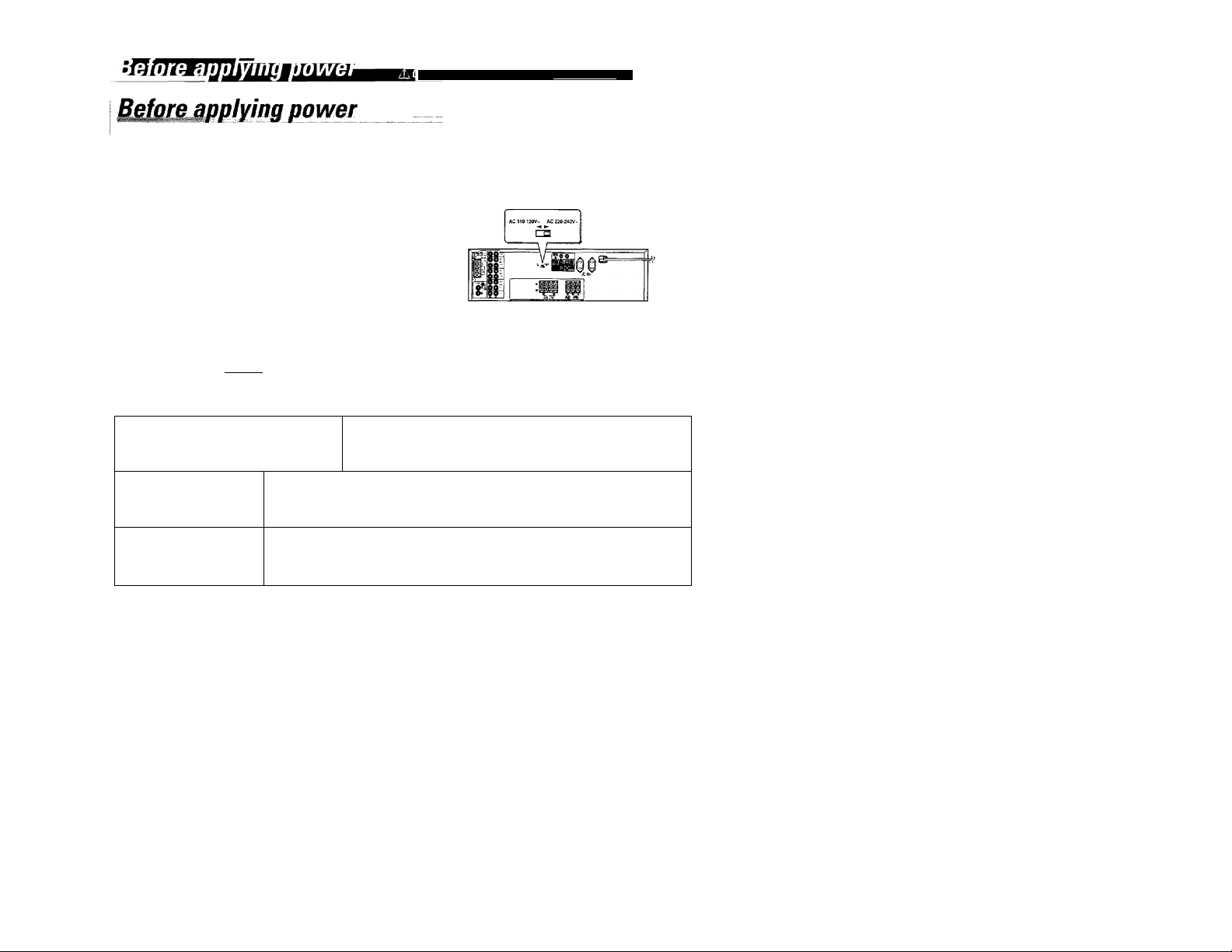
AC voitage sefection
This unit operates on 110 - 120 volts or 220 - 240 volts
AC. The AC voltage selector switciTon the rear panel is
set to the voltage that prevails in the area to which the
unit is shipped. Before connecting the power cord to your
AC outlet make sure that the setting position of this
switch matches your line voltage. If not, it must be set to
your voltage in accordance with the following direction.
Our warranty does not cover damage caused by excessive line volt
age due to improper setting of the AC Voltage selector switch.
AC voltage selector switch
Move switch lever to match your line voltage
with a small screwdriver or other pointed tool.
Mofeta precautions
WARNING
FortheU.S.A.
FCC WARNiNG
This equipment may generate or use radio frequency energy. Changes or modifications to this equipment may cause harmful interference
unless the modifications are expressly approved in the instruction manual. The user could lose the authority to operate this equipment if an
unauthorized change or modification is made.
NOTE:
This equipment has been tested and found to comply with the limits for a Class B digital device, pursuant to Part 15 of the FCC Rules. These
limits are designed to provide reasonable protection against harmful interference in a residential installation. This equipment may cause harmful
interference to radio communications, if it is not installed and used in accordance with the instructions. However, there is no guarantee that
interference will not occur in a particular installation. If this equipment does cause harmful interference to radio or television reception, which
can be determined by turning the equipment off and on, the user is encouraged to try to correct the interference by one or more of the following
measures: .
— Reorient or relocate the receiving antenna.
— Increase the separation between the equipment and receiver.
— Connect the equipment into an outlet on a circuit different from that to which the receiver is connected,
— Consult the dealer or an experienced radio / TV technician for help.
TO PREVENT FIRE OR ELECTRIC SHOCK, DO NOT EXPOSE THIS APPLIANCE TO RAIN
OR MOISTURE.
CAUTION; TO REDUCE THE RISK OF ELECTRIC SHOCK. DO NOT REMOVE COVER
[OR ВАСЮ. NOUSER-SERVICEABLEPARTSINSIDE, REFER SERVICING TO QUALIFIED
SERVICE PERSONNEL.
THE LIGHTNING FLASH WITH ARROWHEAD SYMBOL. WITHIN AN EQUILATERAL TRIANGLE, IS
INTENDED TO ALERT THE USER TO THE PRESENCE OF UNTNSULATED "DANGEROUS VOLTAGE"
WITHIN THE PRODUCT’S ENCLOSURE THAT MAY BE OF SUFFICIENT MAGNITUDE TO CONSTITUTE A
A
A
RISK OF ELECTRIC SHOCK TO PERSONS.
THE EXCLAMATION POINT WITHIN AN EQUILATERAL TRIANGLE IS INTENDED TO ALERTTHE USER TO
THE PRESENCE OF IMPORTANT OPERATING AND MAINTENANCE [SERVICING) INSTRUCTIONS IN THE
LITERATURE ACCOMPANYING THE APPLIANCE,
FortheU.S.A.
Note to CA TV system instaher:
This reminder is provided to call the CATV system installer's attention to Article 820-40 of the NEC that provides guidelines for proper
grounding and, in particular, specifies that the cable ground shall be connected to the grounding system of the building, as close to the point of
cable entry as practical.
Page 3
SpecialJeatures
mmxmuQSULMmLimimL
The surround system reproduces vìdeo software programes
carrying the ixiioonYsunwotji«; mark with simifar acoustic effects
to movie theater.
The DOLBY PRO LOGIC made controls the audio signals of the
Front l^ft/Right, Center and Rear surround channels using the
built-in directivity enhancer circuit to reproduce the feeling of
sound motions realistically.
The DOLBY 3 STEREO mode can reproduce the motions of sound
even when only the front and center speakers are used, by
providing proper acoustic position using the directivity enhancer
circuit
Contents
Before applying power
Special feature
System connection
Controls and indicators
Operation of remote control unit
Piaying music
Sound adjustment functions
Recording
Broadcast Reception
Operation of video components >:
Presence play ,.
In case of difficulty
Specifications
Caution.^ marked ^car^^ ensuraa^
A Before applying power................................................................................................ 2
Safety precautions...............................................................................................................2
....
........................................................................................................
.
....................
......
...................
......................
.
.........................
Receiving broadcast station........................................................................................... 15
Receiving radio station by specifying its frequency
Storing radio stations In mamory (Station preset)........................................................... 17
Playback of videotape...................................................................................................... 18
Recording of video source............................................................................................. 18
Dolby Pro Logic surround adjustment
Dolby Pro Logic surround playback.........
Dolby 3 Stereo adjustment and playback ..
............................................................................................................10
....
.......................................................................................................... 11
..........
..............................................................
........................................................ 16
„....8
.... 20
...
...
....
....
4
19
21
22
23
24
Page 4
mi4nE4>hiM»kwri
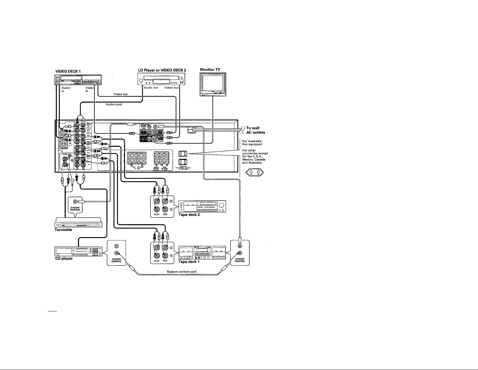
: Make connection as shown below. When connecting the related system components, refer also to the instruction manuals o
the related components.
4
Do not plug in the power lead until all connections are completed.
Automatic operation
When this unit is connected to KENWOOD system components such as a cassette deck and CD player through system control cords and the inpu
source is selected with the INPUT SELECTOR, the selected component starts to play automatically. Inversely, playing a component automatical!'
selects that source as the input to this unit. The automatic operation also occurs when the provided remote control is used.
“T7“Cdnnect all cords firmly. If connections are loose, there could be loss of sound or noise, produced,
I Notes I
2. When plugging and unplugging connection cords, be sure to first remove the power cord from the AC outlet. Plugging / unplugging
connection cords without removal of the power cord can cause malfunctions or damage to the unit.
3. Do not connect up a power source which is larger than that indicated on the socket at the rear of the unit.
4. Insert the systecn control plugs completely into the jacks.
5. If the system control cords or audio cords are not connected properly, the remote control or automatic operation between system
components will not work properly.
Page 5
Connejoiion^
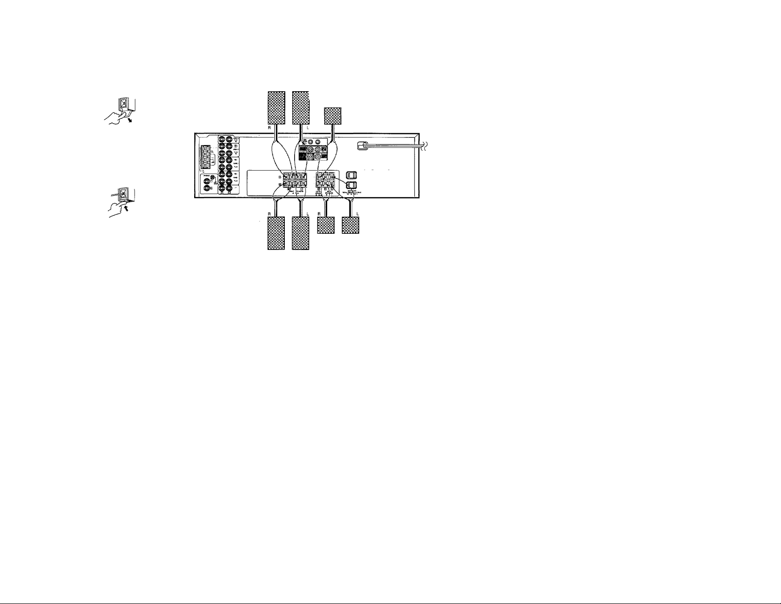
(D Push lever.
<D Insert cord.
(3) Return lever.
SPERKER SYSTEM A
Center speaker
(sa - len)
► Never short-circuit the + and - speaker cords.
I If the left and right speakers are connected inversely or if the
speaker cords are connected with reversed polarity, the sound
becomes unnatural with ambtgous acoustic image positioning.
Be sure to connect the speakers and speaker cords correctly.
► Proper sound will not be produced unless two rear speakers are
connected.
SPERKER SYSTEM B
Rear speaker
(8Q ~ 16ii)
Page 6
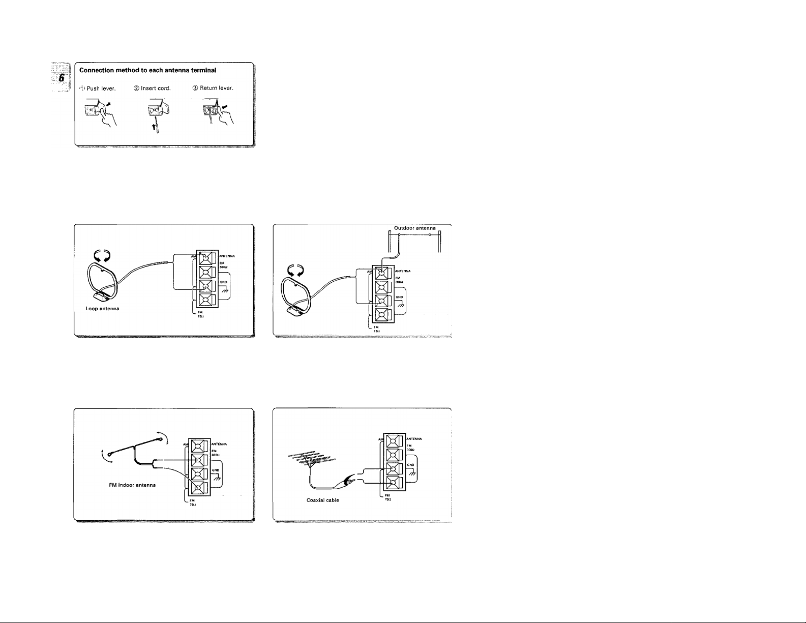
AM loop antenna connection
The supplied antenna is for indoor use. Place it as far as possible
from the main system, TV set, speaker cords and power cord, and
set it to a direction which provides the best reception.
Connectìqnp
FM indoor antenna connection
The supplied antenna is for indoor use. For stable reception, re
move the indoor antenna after installing an outdoor antenna as
soon as possible.
AM outdoor antenna connection
If the reception is poor when the AM loop antenna is used, dis-.
tribute a vinyl-coated wire of more than 6 meters outdoors, with
out disconnecting the loop antenna.
FM outdoor antenna connection
Lead the 75£i coaxial cable connected to the FM outdoor antenna
into the room and connect it to the FM 75Q terminal.
Page 7
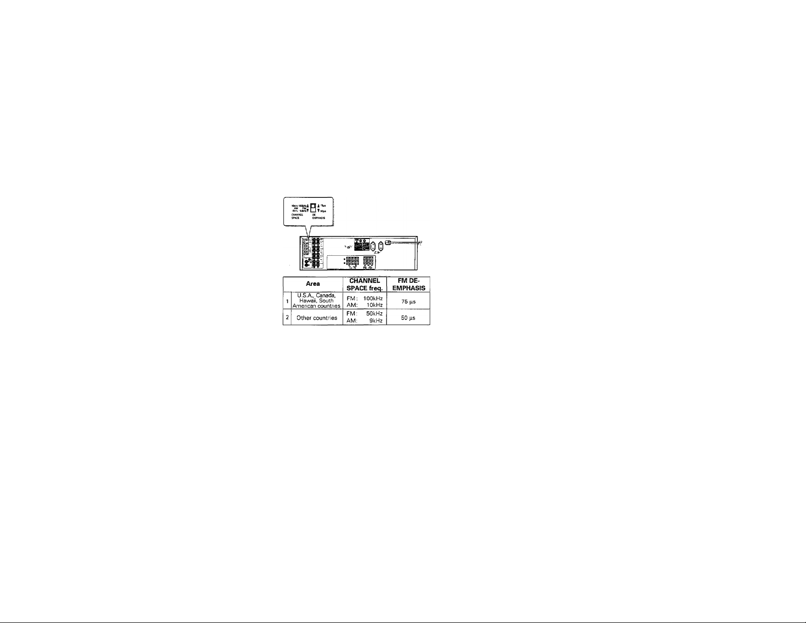
FM DE-EMPHAS/S/CHANNEL SPACE switch
(Except for U.SA, Canada, Mexico and Austraiia)
The FM DE-EMPHASIS / CHANNEL SPACE switch on the rear
panel is set to the correct setting that prevails in the area to which
the unit is shipped, However, if the FM DE-EMPHASIS / CHAN
NEL SPACE setting is not matched to the area where the unit is to
be used; for instance, when you moved from area 1 to area 2 or
vice versa, desired reception of AM / FM broadcasts is not ex
pected. In this case, change the FM DE-EMPHASIS / CHANNEL
SPACE setting in accordance with the area corresponding to the
table. The FM DE-EMPHASIS is switched over at the same time.
► When changing the setting of the FM DE-EMPHASIS / CHAN
NEL SPACE switch, first disconnect the power cord of the am
plifier, then reset the channel spacejswitch, connect the power
cord again, and turn the power on.
Page 8
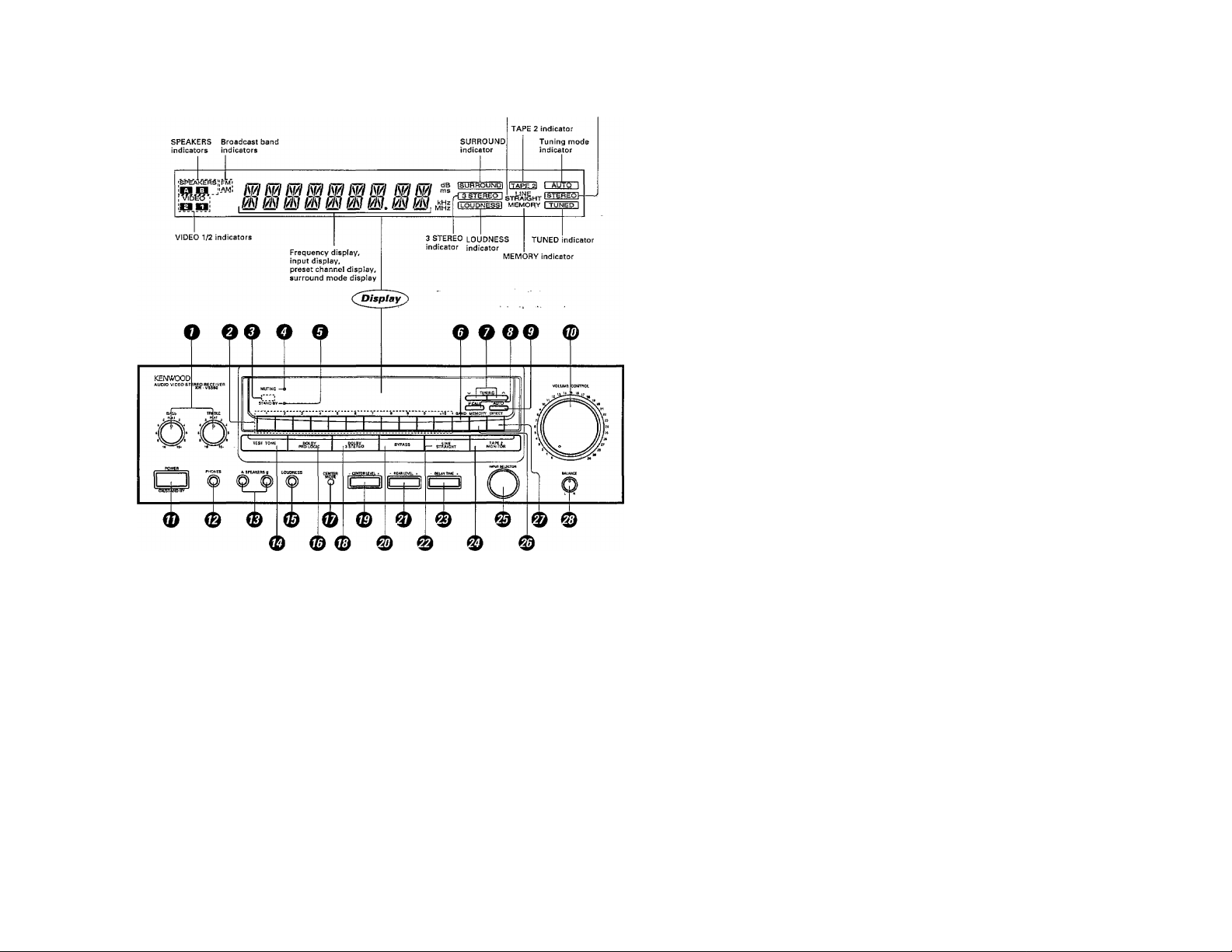
Tni-MiMìMIWltifilcai:
L!NE STRAIGHT
indicator Reception mode tndicator
s
OTOÑE control knobs
ONumeríc keys
ORemote control sensor
OMUTING indicator
0STAND BY indicator
©BAND key
Press to switch the broadcast band.
OTUNING keys
Press to tune broadcast stations.
©P.CALL key
Press to recall a preset station.
0AUTO key
Press to select the auto tuning mode.
©VOLUME CONTROL knob
©POWER key
©PHONES jack
Used for headphone listening.
STANDYBYmode of POWER switch
When the power cord of this system is plugged into an AC outlet, the STAND BY indicator lights up regardless of. the ON/OFF setting ofthc
POWER switch. This indicates that a small amount of current is being supplied to the unit to back up the memory contents. This mode is referred;
to as the Stand By mode. While the STAND BY indicator is lit the power of the system can be switched ON/OFF from the remote control unit.
©SPEAKERS A/B keys
Press to select the A and/or B speaker sys
tems.
©TEST TONE key
©LOUDNESS key
Press to enhance low frequencies.
©DOLBY PRO LOGIC key
©CENTER MODE key
Press to select the center mode of the
DOLBY PRO LOGIC surround play.
©DOLBY 3 STEREO key
©CENTER LEVEL key
©BYPASS key
Press to cancel the surround modes.
© REAR LEVEL key
©LINE STRAIGHT key
Press to reproduce the source with a highei
sound quality.
©DELAY TIME key
Press to adjust delay time.
©TAPE 2 {MONITOR) key
©INPUT SELECTOR knob
Turn to select the input sources.
©MEMORY key
Press to preset a station in the memory.
©DIRECT key
Press for direct station tuning based oi
numerical input.
© BALANCE control knob
Turn to adjust the volume balance between
left and right.
Page 9

The remote control unit provided with the receiver can also control KENWOOD cassette decks, CD player, and graphic equalizer
connected to the receiver through system control cords. For details of the controllable functions, refer to the instruction manuals
of these components.
TUNER operation keys
BAND Selects the broadcast band.
P.CALL Recalls preset stations.
CD player operation keys
DISC This key is used as the disc
selector of a multi-CD player.
Each press selects a differ
ent disc,
INPUT key
Selects the input sources.
TAPE 2 (MONITOR) key
Press to monitor the source being re
corded.
POWER key
MUTE key
Mutes the sound temporarily.
VOLUME keys
Adjust the listening volume. The VOL
UME CONTROL knob of the main unit
turns when these keys are operated.
^ WiA ^
C3 a
LÓ a
TJNEJl
BAND m
REC/APM ^ ■
ao_
a CD CD CD
“ ■ ►/!!
-a a a a
SURROUND
^DELAY^ ^R£AR^ CENTER
MULTILEVEL CONTROL
TAPE2
INPUT WONrTQRl
-dD Q
VOLUME)CDIMNTHOL
qp
TAPES
□ CD
a a
DISC
MUTE
CD
C±)
Cassette deck operation keys
These keys are used to operate TAPE
A and TAPE B decks.
REC/ARM key
When recording on TAPE B. puts the
deck in record-pause mode after leav
ing a non-recorded blank of 4 seconds.
Graphic equalizer operation keys
EFFECT Turns the graphic equalizer
ON and OFF.
M.CALL Recalls the preset equalizer
curves from memory.
SURROUND keys
SURROUND MODE
Switches the surround modes.
TEST TONE
Switches the test tone ON and OFF.
CENTER + MULTI LEVEL CONTROL
This combination adjusts the center
level,
REAR + MULTI LEVEL CONTROL
Adjusts the rear level.
DELAY + MULTI LEVEL CONTROL
Adjusts the delay time.
J
KENWOOD
REMOTE CONTROL UNrr
RC-R0502
Model: RC-R0502
Infrared ray system
Page 10

mmiiJjWiuiéihmiMimiiiiiiU
„t lg§4iiig batteries
f Remove the cover.
I Insert two AA-size (R6 i SUM-3) batteries as indicated .by the po
larity nnarking.
MPGratioB procedure
Plug the power cord of the system into an AC wall outlet
and press the POWER key on the remote control unît to
turn the power on.
When the power is turned on, press the key of the source
component to be operated.
Remote control
• When two operation keys on the remote control unit are pressed
successively, press each key securely reserving an interval of mor_e
than 1 second for each press,
• Componerits connected, via the system control cords, such as the
CD player, can also be remote-controlled. In this case, please read
the instruction manual supplied with your components.
1. The supplied batteries are intejnded for use in operation checks. Therefore, their lives may be shorter than ordinary batteries.
I Notes 1
2. When the remote-controllable distance gels shorter than, before, replace both batteries with new ones.
3. Malfunction may occur if direct sunlight or the light of a high-frequency lighting fluorescent lamp enters the remote control light
sensor. In such a case, change the system installation position to prevent the malfunction.
Page 11

II - "Sil|
1 i-rr^yrr i-r.rrr-rTi 1
oo
el
A 0 # 0 =. a[=3i=i H
A, B OFF
Sound is not output from the speakers. Use this setting for lis
tening through headphones, etc.
A ON
Sound is output from the speakers connected to the SPEAKERS
A terminals on the rear panel.
B ON
Sound is output from the speakers connected to the SPEAKERS
B terminals on the rear panel.
A, B ON
Sound is output from the speakers connected to the SPEAKERS
A and B terminals on the rear panel.
• When a surround mode is activated while both SPEAKERS A and B
are ON, the SPEAKERS B system is automatically switched off. If
the SPEAKERS B key is pressed at this time, the SPEAKERS B sys
tem is switched ON and.the SPEAKERS A system is switched OFF
automatically.
• If the cassette deckfs), CD player and/or turntabie is connected
through system control cords, the component of the selected input
source starts to play automatically.
The input sources are switched in
the following order:
—^<T) TUNER (frequency display)
ij) TAPE 1
(3) VIDEO 1
<i) VIDEO S
® CD
>-►(1) PHONO
The selected input source is held in memory for about 3 days even
after the power cord is unplugged from the mains outlet.
The selected source is
displayed.
r 77
L JJ
( The sound of input source cannot be listened to while TAPE 2 is
ON.
* When the volume is adjusted from the remote control unit, the
VOLUME CONTROL knob rotates.
Page 12

wrnrnnrnnmfmmrmf:
12:
Adjusting the tone
Adjusting the ieft/right sound balance
Using the LOUDNESS key
When listening at a low volume, the loudness function allows to
compensate the low frequencies which human ears have difficulty
in hearing at a low volume.
To mute sound temporarily
To cancel the loudness function
Press the key again.
The MUTING indicator of the receiver unit blinks.
-T-—
Page 13

To iisten through headphones
Line-straight playback
This feature allows to enjoy music sources such as CD with an even
higher sound quality.
• The tone control functions are defeated during line-straight play.
• The tine-straight play Is cancelled when a key associated with sur
round play is pressed.
To cancel
Press the key again.
Page 14

M
Mcqrjimu
To record a music source
Copying tape (Tape dubbing TAPE2^ TAPE 1}
> For copying tape using a double cassette deck, read the instructioi
manual of the double cassette deck.
Copying tape (Tape dubbing TAPE 1 TAPE2)
Play the cassette deck connected to the TAPE 1 jacks and start
recording of the cassette deck connected to the TAPE 2 jacks.
Synchro recording
By connecting this unit to a CD player or turntable manufactured by KENWOOD through a system control cord, the CD or analog disc sound can brecorded with a simple operation on the cassette deckts)..
Select the music source to be recorded with the INPUT SELECTOR and put the cassette deck in record-pause mode. With this condition, press th^
play key of the CD player or turntable to start recording at the same time as the source component starts to play.
______
Page 15

Receiving broadcast ^tMon
The input sources are switched in the following order;
'© TUNER (frequency display) I
(D TAPE 1 ___________
© VIDEO 1
PHONO IU O Li
> The last frequency tuned before is displayed.
Each press switches the band as follows;
^ AM or FM indicator
-®FM [
I—F
t'AM
I—►(E'i
Each press switches the turning method as follows;
•© AUTD lit (auto tuning)
at
AUTO not lit (manual turning)
► Usually, set the switch to AUTO (auto tuning}.
Select manual tuning when noise interferes due to weak radio wave, (The
stereo broadcasting is received in monaural during manual tuning.)
Frequency display
inriri
_________
speaker;
o
VIDEO
___________
I
Frequency display
inp rn
lUL.JU.
Auto tuning: The next station found is tuned automatically.
Manual tuning: Press repeatedly or hold until a station is tuned.
"TUNED" lights up when
a station is turned.
Page 16

RecemiM station by specifym^^^ its frequency
The input sources are switched in the following order:
® TUNER (frequency display)
d) TAPE 1
(3) VIDEO 1
® VIDEO S
'D CD
- PHONO
Each press switches the band as follows;
I—►iOFM
I—AM
Press the nunneric keys according to the frequency to be tuned <
shown below.
AM 810 kHz
AM 1260 kHz
FM 90 MHz...........9, 0, O. 0
..........
8. 1. O
8, 1
........
1, 2, 6, 0
1, 2. 6
FM 102.5 MHz ,.,.1, O. 2, 5,
y If you commit a mistake, repeat step 3 again,
9. 0, O
1. O, 2, 5
Frequency display
mo cn
lUL.DU,
Frequency display
in pi~i
lU uu
AM or FM indicator
SPEAKEI
o
VIDEO
(9 kHz space)
{10 kHz space)
(9 kHz space)
(10 kHz space)
(50 kHz space)
(100 kHz space)
0 (50 kHz space)
(100 kHz space)
"TUNED" lights up when
a station is tuned.
Page 17

Preparation
*E^
I Tune the station to be stored
mennory.
M^rimw^iQStaUomJnmmQj^ (Station preset)
/ Press the MEMORY key during receiving a station.
Proceed to step 2 within 5 sec.jilf more than 5 sec. have
elapsed, press the MEMORY key again^}
2 Select one of the preset numbers from 1 to 20.
OAHt> MEMORY OtREirr
n ' I ’ I ^
Mrmíyíms P^^setghatím
Press the preset number of the desired station.
CT) Select the TUNER input with the
@
! TUNER ir
.ECTOR.
INPUT SELECTOR.
1-1 I I I
Lights up (for 5 sec.)
inpori
i U L
Press the numeric keys in the following order.
To store in “15"........+1Q, 5
To store in "20"
• Repeat steps 1 and 2 for each of the stations to be stored in
memory.
e If a station is stored in a preset number which already stores a sta
tion memory under it, the previous memory is replaced by the new
memory content.
• Once the memory content has been preset, it is held for about 3
days even after the powercord is unplugged from the mains outlet.
SPEAKERS f
o
VIDEO
Press the numeric keys in the following order.
To recall "15"
To recall "20"
_
J U MHZ
.......
+10. +10, O
/5
..........
+10, 5
...........
+10. +10, 0
inp rn
lUL.JU.
I AU-fOn
----- ISTEREOI
Bmmvma ail preset stations in order
• Every time the key is pressed, the next station in the order of the.
preset number is received.
If the key is held pressed , .„Preset stations will be received succes
sively for about half a second each.
Page 18

eration ot viaeo com
I For the conneotions and operations, also read carefully the
1 instruction manuals of the video components.
iliLMlK:
Playback of videotape
/ Turn the power of the monitor TV ON.
Recording of video source
/ Connectthe video source componentto be played.
o o
0 1 O O O O O p—Bi—irTrn
The input sources are switched in the following order;
"■<T) TUNER (frequency display)
(2) TAPE 1
(V VIDEO 1
M ) VIDEO 2
(5> CD
PHONO
I Sele.c_t the input to which a video deck is connected.
I Connect the component to be played to the VIDEO 2 jacks.
» The connectable components include a video deck (playback only),
video camera (playback only), L_D player or DBS tuner.
The input sources are switched in the following order:
"H) TUNER (frequency display)
2) TAPE 1
v3) VIDEO 1
4 VIDEO 2
(5i CD
>—► (6; PHONO
^EO
SPEAKERS
“eo
-f-t t-HW
"VIDEO 1" should be
displayed.
1/ r Tirn {
y ± jjL l ■ ' .U i
"VIDEO 2" should be
displayed.
// T T
y ± JJ
i
ipnp
4 Start recording on the recording video deck.
...
------
I Start recording with the video deck which is connected to the VIDEO
1 jacks.
Page 19

The surround modes allow to enjoy the feeling of presence in music. Select the mode according to the source or components
played. For the connections of the rear and/or center speakers, refer to "Connection of speakers", h.
DOLBY PBO LOGIC surround mode
Video and LD software programes carrying themrs
mark contain recording of the same Dolby Surround data as
those used in movie theaters. The DOLBY PRO LOGIC sur
round mode uses tiie Dolby Surround data and brings into
home a similar sound field with full of presence to movie
theatres.
To use this mode, connect the rear (and center) speakers.
DOLBY 3STEBB0 mode
If the left and right speakers are installed apart from each
other, the center acoustic image (words, etc.) may vary
depending on the listener's position. The DOLBY 3 STEREO
mode provides an improved positioning of the center acous
tic image regardless of the listening position.
To use this mode, connect the center speaker.
Center speaker
In case center speaker Is not used
Center speaker
n
Q-
♦
_11__
Main speakers
■Q
1
Manufactured under license from Dolby Laboratories Licensing Corporation. Additionally licensed under one or more of the following patents: U.S.
numbers 3,959,590; Canadian numbers 1,004,603 and 1,037,877.
"Dolby", "Pro Logic"and the double-D symbol □□ are trademarks of Dolby Laboratories Licensing Corporation,
Page 20

I This mode provides a similar Dolby Surround effect used in movie theaters when a video (or LD| software programs carrying the
i CniPowawiBotitMi mark is piayed.
w
/ Activate the DOLBY PRO LOGIC mode.
(D
Each press of the CEWTER MODE key switches the center modes ae
[) Select the center mode using a
sharp object (such as a ball-point
pen).
follows:
® NORMAL : When the center speaker is a compact-sized spe.
® WIDEBAND : When the center speaker is a medium- or large-
C
@ PHANTOM : When the center speaker is not used.
• If you cannot tell whether your center speaker is compact or me
dium-sized, try two modes and select according to your liking.
• The selected center mode is automatically stored in memory anc.
held unless, it is changed later.
► The test tone which is heard like noise moves between speakers a
an interval of 1.5 sec.
In NORMALand WIDEBAND
modes:
Left tL]
Center (C)
Right ¡R)
Surround (Rear) (S)
:
» Be sure to adjust from your listening position.
► When a key is pressed, the corresponding volume level to tKe key is
displayed on the display, While the level is displayed, it can be ad
justed by 1 dB per press of the key.
► The volume levels can be adjusted in thejange from -10 dB to +1C
dB,
SPEAKEfiS
O
VIDEO
speaker,
rre T
i LJ i
In PHANTOM mode;
Left (U
Right (R)
c
Surround (Rear) (S)
I
L
How to calculate the proper delay time
I When the DELAY TIME key is pressed, the delay time is displayed
on the display.
I The delay time can be adjusted in the range from 15 ms to 30 ms, in
5 ms steps,
I Set the closest value to the value obtained with method (1) or (2)
below.
I Once the delay time has been preset, it is held until it is re-set later.
0 Use the delay time calculation chart below;
Example: When A = 3 m,
B = 3m, the delay time
is 20 ms.
0 Use the following formula for calculation.
Delay time = 20 + 3 x (A - B) [Unit; ms)
Page 21

Before playing a video (or LD| software program carrying
the □PlooiLwyww«^ mark, be sure to complete the "DOLBY
PRO LOGIC surround arrangement".
MMMYBROLOMCsmmund^^^^
Each press of the key switches the modes as follows:
C
2 Play a video software program.
(DPRO LOGIC
@ 3 STEREO
iD OFF (BYPASS)
Lights
To cancel DOLBY PRO LOGIC SURROUND piay
Page 22

This mode improves the positioning of the acoustic image
j s of words, etc., by applying directivity enhancer processing
I and using an additional center speaker when a video softI ware program recorded with ordinary 2-channel stereo is
played.
/ Activate the DOLBY3 STEREO mode.
Ptaya video software program.
(Z:
O
(|) Select the center mode using a
sharp object (such as a ball-point
pen).
Each pn
follows,
I—► O ' NORMAL : When the center speaker is a compact-sized
I— WIDEBAND : When the center speaker is a medium- or
I If you cannot tell whether your center speaker is compact or me
I The selected center mode is automatically stored in memory an*
• The test tone which is heard like noise moves between speakers a
I—► Left (L)
I
----
■ Be sure to adjust from your listening position.
■ When a key is pressed, the volume level is displayed on the dis
» The center level can be adjusted in the range from -10 dB to +10
• The center level is stored in memory as the common settings
of the CENTER MODE key switches the center modes a;
O ' NORMAL
WIDEBAND :
dium-sized, try two modes and select according to your liking.
held unless it is changed later.
an interval of 1.5 sec.
Center to
Right (R)
play, While the level is displayed, it can be adjusted by 1 dB per
press of the key.
dB.
with the DOLBY PRO LOGIC surround mode.
To cancel DOLBY 3 STEREO piar
speaker,
large-sized speaker,
SPEAKERS
o
VIDEO
rrr T
i L J i
i
^ Adjust the voiume.
&
VOUJMECONTBDL
a a
Page 23

Remote control unit
Remote control operation is not possible.
Amplifier
.....
Sound is not output.
The STAND BY indicator blinks and sound
is not output.
Sound is not output from one of the speak
ers.
Sound is not output from the Surround
rear speaker and/or center speaker, or
their sound is very small.
A hum noise is generated when PHONO
input selector key is pressed.
Tuner
Radio stations cannot be received.
Interference.
A station which was preset cannot be re
ceived by pressing the corresponding nu
meric key.
• Batteries are exhausted.
• The remote control unit is too far away from
the main system, controlling angle is too
large, or there is an obstacle in between,
• The audio cords and system control cords are
not connected properly,
• The source component to be operated does
not contain the tapéis) or CD.
• An attempt is made to play a tape which is
being recorded in the cassette deck.
Causa
• The speaker cords.are disconnected.
• The VOLUME is set to the minimum position.
• The sound is muted. (The MUTING indicator
is blinking.)
• The SPEAKERS switches are set to OFF..
• The TAPE 2 key is set to ON.
• Speaker cords are short- circuited.
• The speaker cord is disconnected.
• The BALANCE control is set to an extreme
position.
• The rear-speaker cords and/or center
speaker cord are disconnected.
• A surround mode is not selected.
• The REAR VOL. and/or CENTER VOL. con
trols are set to the. minimum level.
• The audio cord from the turntable is not in
serted securely into the PHONO jacks.
• The turntable is not grounded.
___________
• No antenna is connected.
• The broadcast band is not set properly.
• The frequency of the desired station is not
tuned
• Noise due to ignition noise of an automobile.
• Noise due to an influence from an electric
appliance.
• Noise due to a nearby TV set.
• The preset station belongs to a frequency
that cannot be received.
• The preset memory was cleared because the
power cord had been unplugged for a long
period of time.
___
....................
-
IRaifiEietfy
• Replace with new batteries.
• Operate the remote control unit within the
controllable range.
• Connect properly referring to "System
connection".
• Place the tapéis) or CD in the source com
ponent to be played.
• Wait unitl the recording is completed.
......
..........
.
• Connect them properly referring to "Sys
tem connection".
• Adjust the volume to a proper level,
• Press the MUTING key to OFF. -
• Set the SPEAKERS switch(es) to ON.
• Set .the TAPE 2 key to OFF.
• Turn the power off, eliminate the short-circuit
ing, then turn on the power again,
• Connect it properly referring "System con
nection",
• Adjust the Left/Right balance.
• Connect them properly referring to "Sys
tem connection",
• Select a surround mode.
• Adjust the REAR VOL. and CENTER VOL
controls.
• Insert the audio cord plugs securely into
the PHONO jacks,
• Connect the grounding wire to the GND
terminal on the rear panel.
.
......
..................
'. Rem«Kly
• Connect an antenna.
• Set the broadcast band properly.
• Tune the frequency of the desired station.
• Install the outdoor antenna apart from the
road.
• Turn off the power of the appliance.
• Install the system more apart from the TV set.
• Preset a station with a receivable fre
quency.
• Preset the station again.
1. This system is microprocessor-controlled, so malfunction may occur due to external noise or interference noise. In such a case,
I Notes 1
unplug thè power cord, plug it and turn power on again.
2. Do not use contact cleaners because it could cause a malfunticon. Be specially careful against contact cleaners containing oil,
because they may deform the plastic components.
Page 24

aution: Head this page caretuuy to ensure safe o,
I (For U.S.A. and Canada]
f ^ Audio section
Rated power output at the STEREO operation
70 watts per channel minimum RMS, both channels driven at
8 O, from 20 Hz to 20,000 Hz with no more than 0.06 % total
harmonic distortions. (FTC)
Power output at the Surround operation
Front (1 kHz, 0.9 % T.H.D. at 8 n)
Center (1 kHz, 0.9 % T.H.D. at 8 n).....................................70 W
Rear (1 kHz. 0.9 % T.H.D. at 8 ii)..........
Total harmonic distortion (1 kHz, 8 U)
Signal to noise ratio (IHF A)
PHONO (MM)......................................
CD, TAPE, VIDEO................... 100 dB
Input sensitivity / impedance
PHONO (MM)
CD, TAPE, VIDEO
Tone controls
BASS
TREBU
Loudness control at - 30 dB level.....
Video section
VIDEO inputs / outputs (Composite).
FM Tuner section
Tuning frequency range ...................... 87.5 MHz ~ 108 MHz
Usable sensitivity (IHF)
50 dB quieting sensitivity
STEREO .............................. 41.2 dBf (32 pV at 75 ii)
Total harmonic distortion at 1 kHz
MONO.........................
STEREO
Signal to noise ratio at 65 dBf (IHF)
MONO.................................................................................. T5 dB
STEREO ............................................................................. 68 dB
Selectivity (IHF + 400 kHz)
Stereo separation (IHF at 1 kHz)
Frequency response
AM Tuner section
Tuning frequency range
Usable sensitivity....................... 12 pV / (500 p V / m)
Total harmonic distortion
Signal to noise ratio .................
Selectivity
General
Power consumption.....................
AC outlet
SWITCHED........................
Dimensions
Weight (net) ................——
.......................................
.............................................
...........................
.............................................. .......... ± 10 dB (at 10 kHz)
..................................................................
..................................................... 30 dB
..............................
..........
........................
....................... 70 W + 70 W
________
20 W + 20 W
....
.........
0.03 % at 50 W
............
75 dB
.....
........
2.5 mV / 47 kii
200 mV / 47 kO
................................± 10 dB (at 100 Hz)
____
....... + 6 dB (100 Hz)
. 1 Vp - p / 75 O
.....................
......................... 530 kHz - 1,700 kHz
.......................................
13.2 dBf (1.2 pV at 75 £1)
..............
0.6 %
0.7 %
................................................
...
.................................... 40 dB
30 Hz - 15 kHz, + 0.5 dB, - 3.0 dB
____________________
______
2: (total 200 W, 1.6 A max.)
..™..„„„..„„W:440 mm (17-5/16")
------
-------
-------------- 9.5 kg (20.9 lb)
...........
H :143 mm (5-5/8")
D :334 mm (13-1/8")
50 dB
0.7 %
48 dB
(For other countries)
Audio section
Rated power output at the STEREO operation
(EIAJ) 1 kHz, 10% T.H.D., at 8 a.........................
(IHF '66) from 20 Hz to 20 kHz,
0.06% T.H.D., at 8 Q
Power output at the Surround operation
Front (1 kHz, 0.9 % T.H.D. at 8 O)
Center (1 kHz, 0.9 % T.H.D. at 8 O)
Rear (1 kHz, 0.9 % T.H.D. at 8 O)...
Total harmonic distortion.......... (1 kHz, 8 Q) 0.03 % at 50 Vv
Signal to noise ratio (IHF'66)
PHONO (MM)
CD, TAPE, VIDEO ........................................................ 100 dE
Input sensitivity / impedance
PHONO (MM) .....................
CD, TAPE, VIDEO.......................................... 200 mV / 47kP
Tone controls
BASS
.............................
TREBLE .................................
Loudness control at - 30 dB level.....
Video section
VIDEO inputs / outputs (Composite)..............! Vp - p / 75 Q
FM Tuner section
Tuning frequency range.......
Usable sensitivity (IHF)
50 dB quieting sensitivity
STEREO
............................................ 41.2 dBf (32 pV at 75 O)
Total harmonic distortion at 1 kHz
MONO ...............................................................................
STEREO.............................................................................
Signal to noise ratio at 65 dBf (IHF)
MONO...
............................................................................
STEREO.............................
Selectivity (IHF ± 400 kHz)
Stereo separation (IHF at 1 kHz)..................................... 40 dB
Frequency response........ 30 Hz - 15 kHz, + 0.5 dB, - 3.0 dB
AM Tuner section
Tuning frequency range
9 kHz
........................................................
10 kHz...............................................
Usable sensitivity..................................
Total harmonic distortion ...............................................
Signal to noise ratio...................
Selectivity.... ......................................................
Generat
Power consumption.......................................................... 260 W
AC outlet
SWITCHED......
(Except for Australia)
Dimensions
Weight (net)
.............................................
...........................
.....
...
.............
__________
...................
....................
.............
..................................... 50 dB
.......................................
..........
....................................
__________
______________
......
....
......................
75 dE
____
± 10 dB (at 100 Hz)
.................................
........
100 W + lOOVv
70 W + 70 Vv
...............
70 W + 70 Vv
.................. 70 Vv
20 W + 20 Vv
................ 2.5 mV / 47 kQ
± 10 dB (at 10 kHz)
_______
+ 6 dB (100 Hz]
87.5 MHz -.108 MHz
13.2 dBf (1.2 pV at 75 O)
0.6 %
0.7 %
75 dB
68 dB
531 kHz - 1,602 kHz
.......
530 kHz - 1,610 kHz
. 12 pV / (500 pV / m)
..............
2: (total 200 W max.)
...
........
____
0.7 %
.......__48 dB
.............
30 dB
.....
W:440 mm
H :143 mm
D :334 mm
_______ 9.5 kg
KENWOOD follows a policy of continuous advancements in development. For this reason specifications may be changed without notice.
I Note I
 Loading...