

Kenwood KRV-1070 Service manual
TAPE/MDCDPHONO
PLAY
IN
REC
OUT
VIDEO1 VIDEO3VIDEO2
PLAY
IN
PLAYINPLAY
IN
REC
OUT
ADAPTOR
INOUT
AUDIO
ƒ
SL 16 XS 8
SUB
WOOFER
SURROUND
FRONT
CENTER
L
R
AUX.6CH.INPUT SYSTEM CONTROL
SIGNAL
GND
L
R
Full Digital Decoding
TRAITR
thermally reactive advanced instantaneous transistor
AUDIO−VIDEO SURROUND RECEIVER 1070VR
PHONES
POWER
1234 567 890
STANDBY
MUTE
LEVEL INDICATOR
DIRECT MEMORY AUTO
TUNINGBAND BASS TREBLE
LEVEL CONTROL
SPEAKERS
A
B
PRO LOGIC 3 STEREO
STEREO DSP
LOUDNESS
SOURCE DIRECT
DIMMER
CENTER MODE
INPUT SELECTOR VOLUME CONTROL
VIDEO
ON/STANDBY
DOWN UP
AV AUX
L
-
AUDIO - R
MUTE
+10
D G
ECODIN
F L
ULL DIGITA
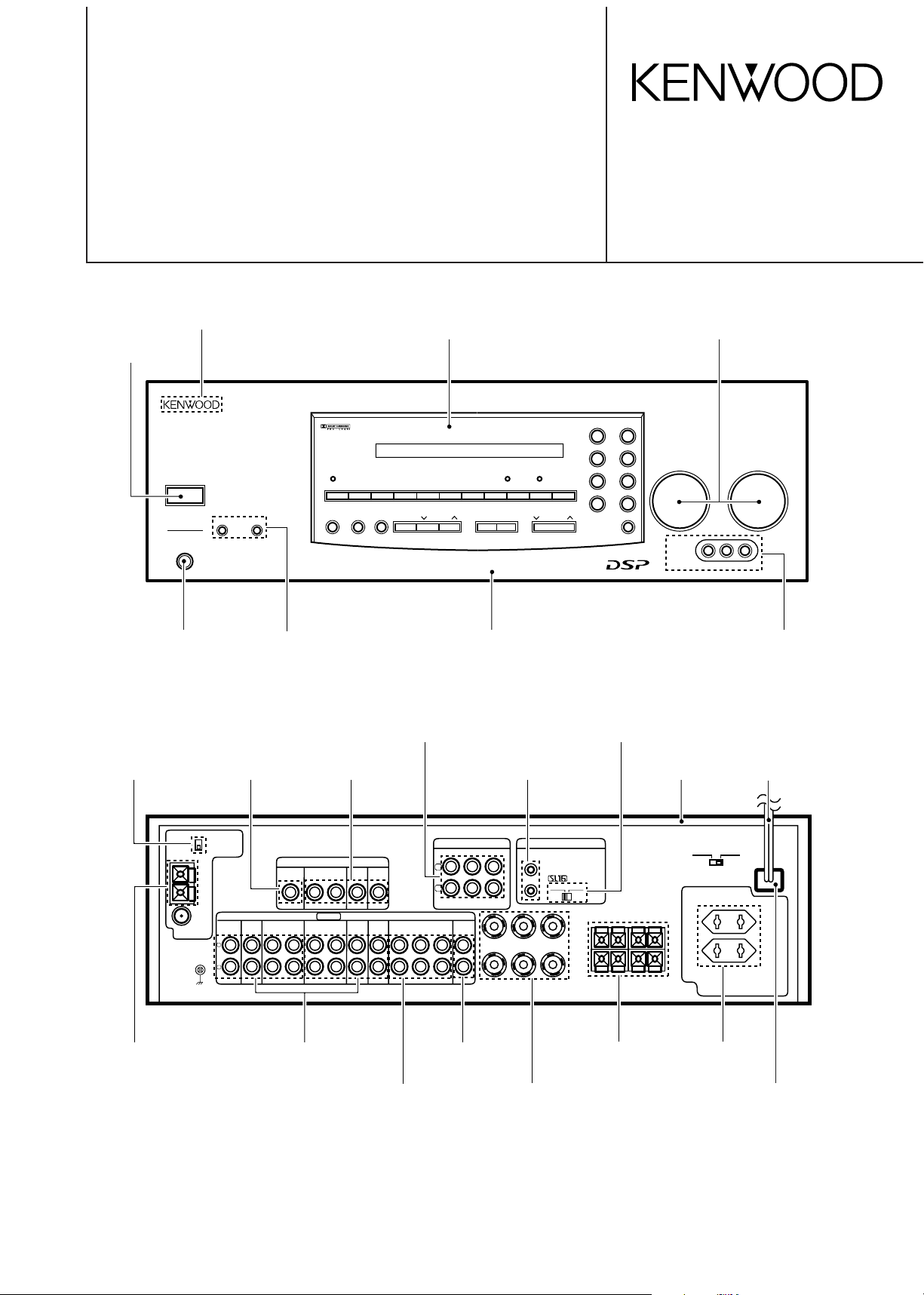
Slide switch
(S31-2132-05)
Phono jack
(E63-0141-15)
Phono jack
(E63-0139-15)
Miniature phone jack
(E11-0293-05)
Screw terminal board
(E70-0049-05)
Slide switch
(S62-0034-05)
Lock terminal board
(E70-0065-05)
Phono jack
(E63-0135-15)
Phono jack
(E63-0163-05)
Phono jack
(E63-0111-05)
Metallic cabinet
(A01-3269-11)
AC outlet *
(E03-)
AC power cord *
(E30-)
Power cord bushing
(J42-0083-05)
Knob(BUTTON) *
(K27-2176-04)
Knob *
(K29-)
Panel *
(A60-)
Phone jack
(E63-1002-05)
Front glass *
(B10-)
Knob
(K29-6247-04)
Phone jack
(E11-0272-05)
Phono jack
(E63-1005-05)
Lock terminal board
(E70-0052-05)
AUDIO VIDEO SURROUND RECEIVER
KR-V8090/KR-V9090
1060VR/1070VR
SERVICE MANUAL
© 1997-6/B51-5322-00 (K/K) 3145
Illustration is 1070VR.
* Refer to parts list on page 36.
KENWOOD badge *
(B43 -0302-04)
1060VR/1070VR/KR-V8090/KR-V9090
AUDIO
SHIFTMACRO
TVVIDEO
GUIDEREC
MUTE
VOLUMETUNING/SKIP
THEME FAVMENU
FUNCTION
SHIFT
SETUP
INFO ALT AUDTV/SAT/VID
REPEAT RANDOM+100
DISPLAY
ENT+10
LISTEN
MODE
SOUNDSUBWOOFER
231
564
897
0
REMOTE CONTROL UNIT
RC-R0805
8
7
4¢
6
BAND
P. CALL P. CALL
POWER
CONTENTS / ACCESSORIES
Contents
CONTENTS / ACCESSORIES ....................................2
CONTROLS.................................................................3
DISASSEMBLY FOR REPAIR.....................................5
BLOCK DIAGRAM.......................................................6
CIRCUIT DESCRIPTION.............................................7
ADJUSTMENT...........................................................16
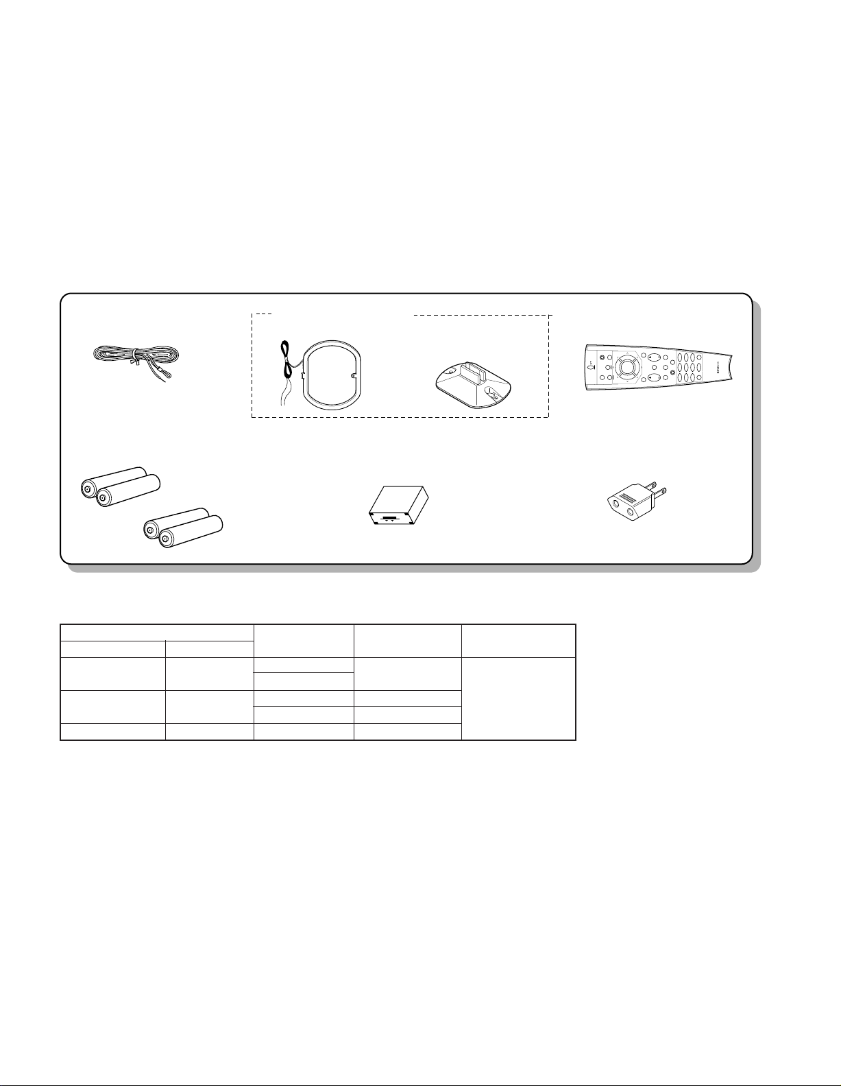
Accessories
WIRING DIAGRAM....................................................17
PC BOARD ................................................................18
SCHEMATIC DIAGRAM............................................27
EXPLODED VIEW .....................................................45
PARTS LIST...............................................................46
SPECIFICATIONS.....................................................59
FM indoor antenna ........(1)
(T90-0810-05)
AM loop antenna ..........(1)
(T90-0820-05)
Loop antenna stand (1)
(J19-3645-05)
Batteries (R03/AA)......... (4)
RF DEMODULATOR.....(1)
(DEM-999D)
M,C,T type only
An use model discrepancy table in of remote controller
Remote controller
Parts number Type name
A70-1115-05 RC-R0805 1070VR All destinations
A70-1117-05 RC-R0605 1060VR All destinations
A70-1118-05 RC-R0606 KR-V8090 T,E,Q
Model name Destination Battery cover
KR-V9090
KR-V8090 C
Remote control unit ......(1)
(A70-1118-05): RC-R0805
Battery cover(A09-0366-08)
AC adapter ....................(1)
(E03-0115-05)
M type only
A09-0366-08
2
1060VR/1070VR/KR-V8090/KR-V9090
3
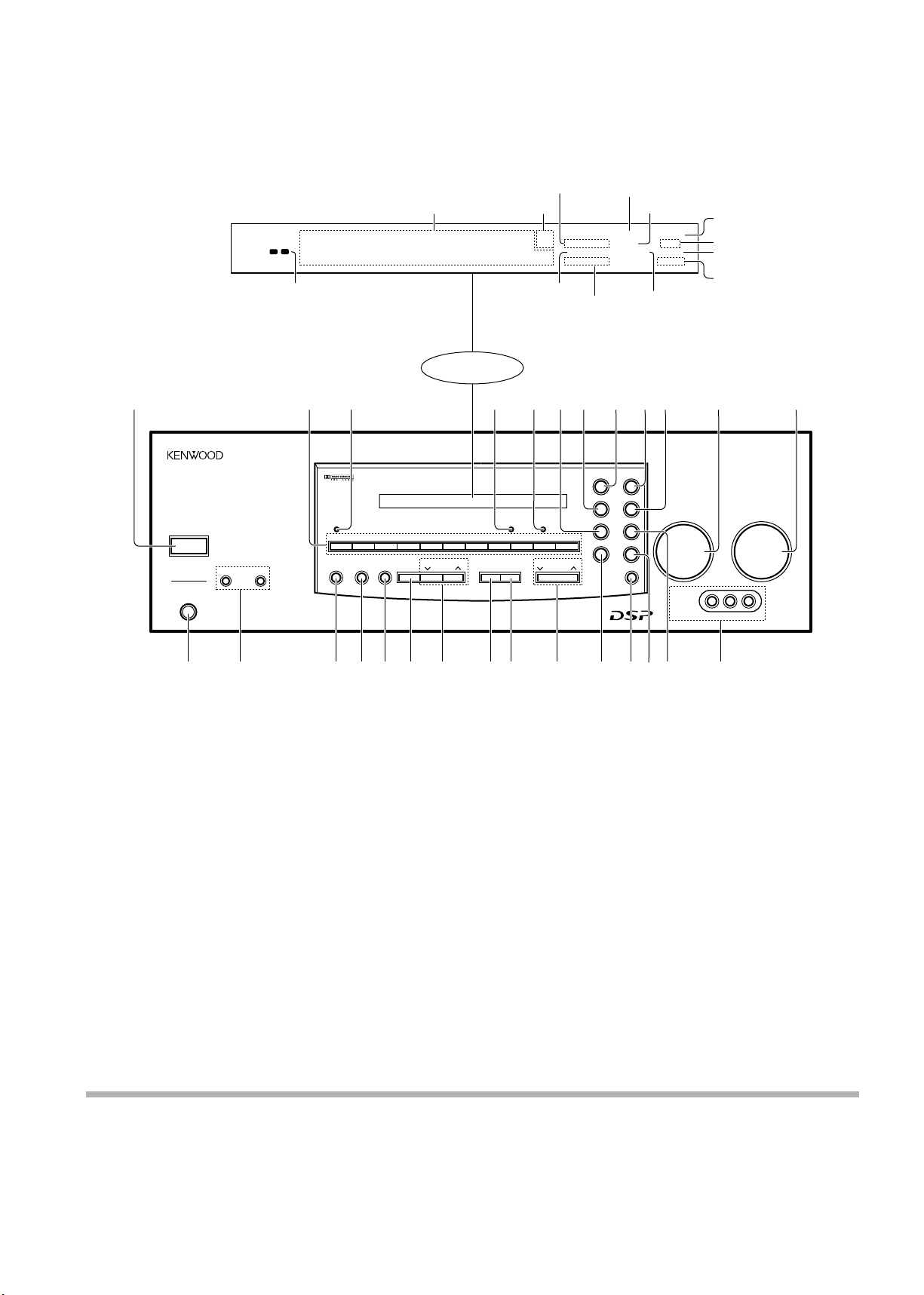
CONTROLS
Full Digital Decoding
TRAITR
thermally reactive advanced instantaneous transistor
AUDIO−VIDEO SURROUND RECEIVER 1070VR
PHONES
POWER
1234 567 890
STANDBY
MUTE
LEVEL INDICATOR
DIRECT MEMORY AUTO
TUNINGBAND BASS TREBLE
LEVEL CONTROL
SPEAKERS
A
B
PRO LOGIC 3 STEREO
STEREO DSP
LOUDNESS
SOURCE DIRECT
DIMMER
CENTER MODE
INPUT SELECTOR VOLUME CONTROL
VIDEO
ON/STANDBY
DOWN UP
AV AUX
L
-
AUDIO - R
A
AC-3
TP SP.
******* **;
FM
AM
kHz
MHz
SURROUND
3 STEREO
DSP
LOUDNESS
M. INPUT
MEMORY
AUTO
STEREO
TUNED
1 2 7 8 0 !3 54 9 @
MUTE
B
A
B
S. DIRECT
+10
£ ¢∞§ ¶# $*&^% ) ¡(™
6
D G
ECODIN
F L
ULL DIGITA
Band indicators
SURROUND indicator
LOUDNESS indicator
3 STEREO indicator
S.DIRECT indicator
About the STANDBY indicator
This unit has a STANDBY indicator. When the STANDBY indicator is lit, the unit consumes a small amount of power to preserve
the memory. This is called STANDBY mode. This mode also lets you turn the power ON using the remote control.
DSP indicator
Display
TUNED indicator
MEMORY indicator
AUTO indicator
STEREO indicator
Frequency display,
Input display,
Preset channel display,
Surround mode display
Speaker indicators
M.INPUT indicator
(1070VR only)
1 POWER key
Use to switch the power ON/STANDBY.
2 Numeric keys
3 STANDBY indicator
4 LEVEL indicator
Lights when the level of the signal being
input is too high.
5 MUTE indicator
6 LOUDNESS key
Use to activate the frequency weighting
network.
7 STEREO key
Use to cancel the surround mode.
8 PRO LOGIC key
Use to turn on the DOLBY PRO LOGIC
mode.
9 DOLBY 3 STEREO key
Use to turn on the DOLBY 3 STEREO
mode.
0 DSP key
Use to turn on, or switch, the DSP mode.
! INPUT SELECTOR knob
Use to select the input sources.
@ VOLUME CONTROL knob
# PHONES jack
Use for headphone listening.
$ SPEAKERS A/B keys
Use to turn the speakers ON/OFF.
% DIRECT key
Use to tune radio stations directly by numerical input.
^ MEMORY key
Use to store radio stations in the preset
memory.
& AUTO key
Use to select the auto tuning mode.
* BAND key
Use to select the broadcast band.
( TUNING keys
Use to tune in radio broadcasts.
) BASS key
Use when adjusting the bass tone.
¡ TREBLE key
Use when adjusting the treble tone.
™ LEVEL CONTROL keys
Use to adjust the level of the selected
tone.
£ DIMMER key
Use to adjust the brightness of the
display.
¢ CENTER MODE key
Use to select the center mode.
∞ MUTE key
Use to mute the sound.
§ SOURCE DIRECT key
¶ AV AUX jacks
1060VR/1070VR/KR-V8090/KR-V9090
4
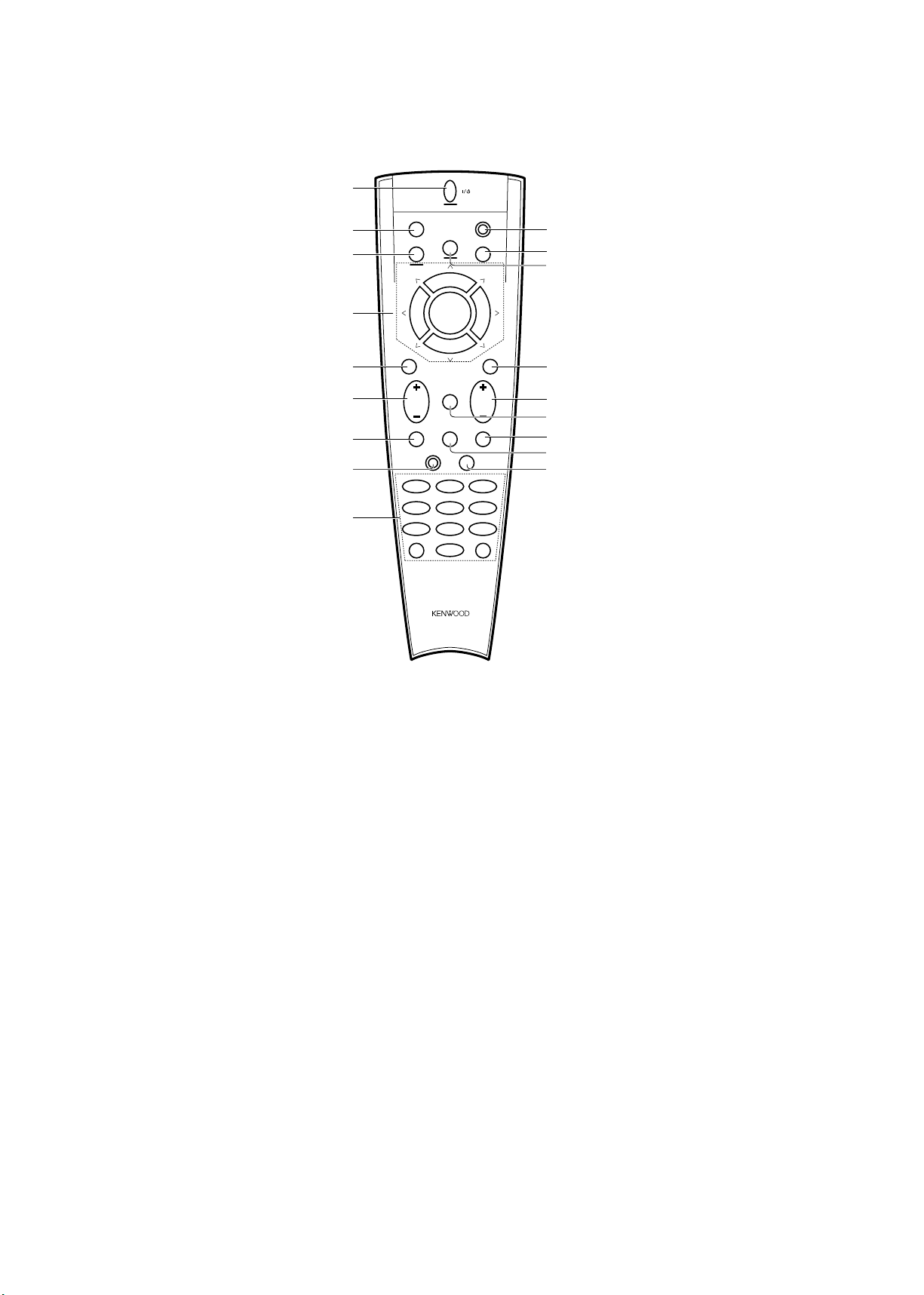
CONTROLS
AUDIO
SHIFTMACRO
TVVIDEO
GUIDEREC
MUTE
VOLUMETUNING/SKIP
THEME FAVMENU
FUNCTION
SHIFT
SETUP
INFO ALT AUDTV/SAT/VID
REPEAT RANDOM+100
DISPLAY
ENT+10
LISTEN
MODE
SOUNDSUBWOOFER
231
564
897
0
REMOTE CONTROL UNIT
RC-R0805
1
2
3
7
8
9
4
5
6
0
!
#
^
*
&
%
@
$
8
7
4¢
6
BAND
P. CALL P. CALL
POWER
1 POWER key
Use to turn the receiver on and off.
Use in combination with the input selector
(AUDIO, VIDEO, or TV) keys and SHIFT
key to turn various components on and
off.
2 MACRO key
Use in combination with the AUDIO, VIDEO, or TV keys to execute a series of
commands automatically (MACRO
PLAY).
3 VIDEO selector key
Selects the video inputs (VIDEO 1,
VIDEO 2, VIDEO 3, AV AUX) and sets
the remote to operate the component registered at the respective input.
4 Multi control keys
Use to operate the selected component.
5 REC key
Use to operate the selected component.
6 TUNING/SKIP key
Use during the setup procedure to specify
various settings. Use to operate the tuner
or selected component.
7 SUBWOOFER key
Use in combination with the VOLUME +/keys to adjust the volume of the
subwoofer.
8 FUNCTION SHIFT key
Use in combination with the numeric keys
to execute alternate commands.
9 Numeric keys
Provide functions identical to those of the
original remote supplied with the component you are controlling.
To access the functions printed above the
keys, Press within 3 seconds of pressing
the FUNCTION SHIFT key. Function
availability varies for each component.
0 SHIFT key
Use in combination with the AUDIO and
VIDEO keys to change the remote control
mode without changing the input selector
or in combination with the POWER key to
turn on and off components programmed
into the remote.
! TV selector key
Sets the remote to operate a TV or cable
box (TV 1, TV 2, CABLE). This key does
not change the input selector on the receiver.
@ AUDIO selector key
Selects the audio inputs (CD, TAPE/MD.
TUNER, PHONO) and sets the remote to
operate the respective KENWOOD audio
component.
If you connect audio components from
KENWOOD and other makers to the
TAPE/MD or CD jacks, you can set the
remote to operate these components by
registering the appropriate setup code at
the respective input.
# GUIDE key
Use to activate the OSD menu functions
of registered components.
$ VOLUME key
Use to adjust the receiver volume.
% MUTE key
Use to temporarily mute the sound.
^ SOUND key
Use to adjust the bass, treble, and input
level.
& LISTEN MODE key
Use to select the desired surround mode.
* SETUP key
Use to adjust the surround setup.
1060VR/1070VR/KR-V8090/KR-V9090
5
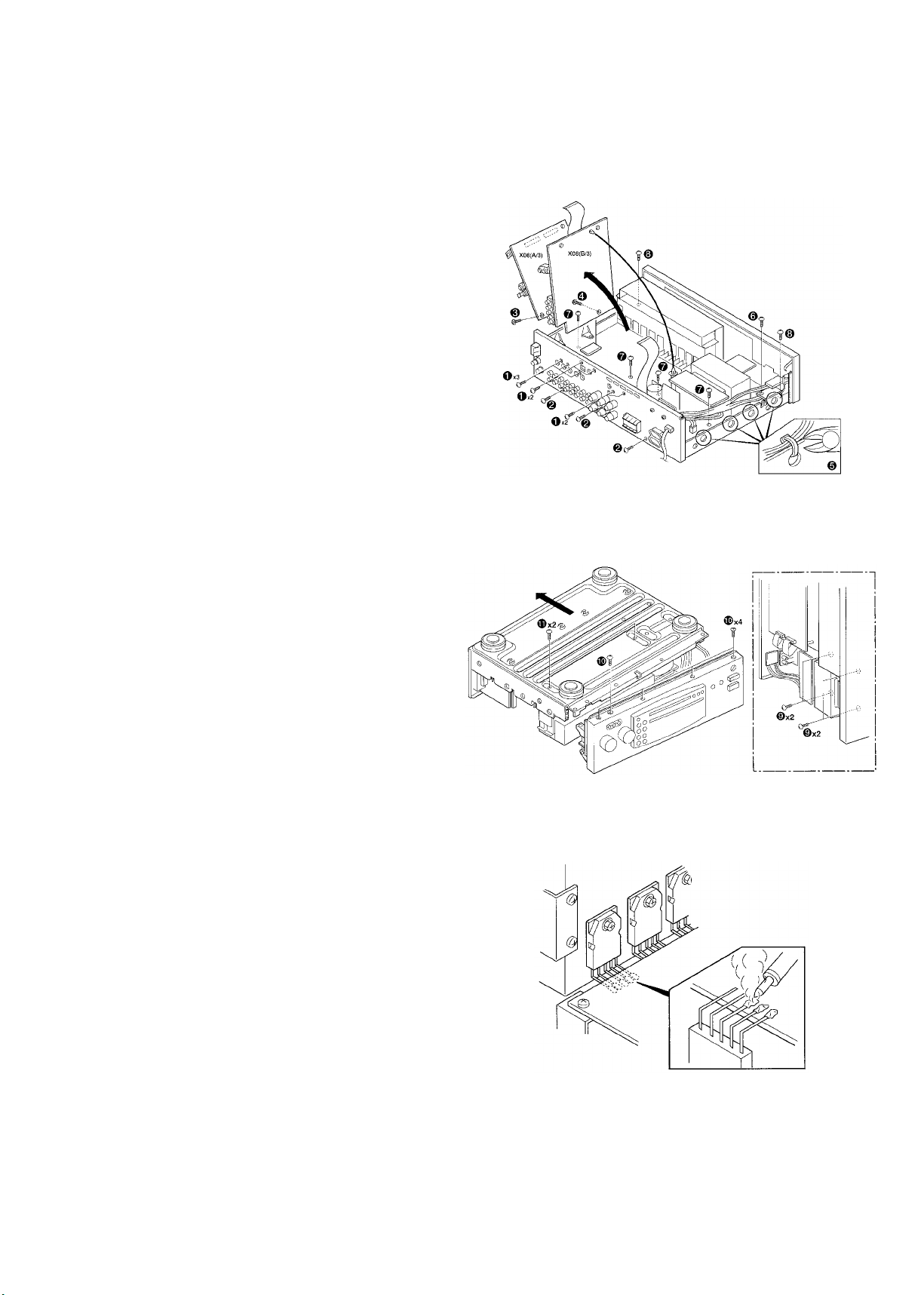
DISASSEMBLY FOR REPAIR
The method that exchanges a power transistor.
1. Remove 10 screws (1 and 2) of rear panels.
2. Remove flat cable from connector (CN851 and CN852) of
printed circuit board X08 (A/3) . And, remove one screw
(
3). After this, move printed circuit board X08 (A/3)
toward the right.
3. Remove one screws (
4) of printed circuit board X08
(B/3). After this, move printed circuit board X08 (B/3)
toward the right.
4. 1) Cut certain 4 convenes with nippers etc. on the left side
of the power supply transformer.
2) Remove one screws (
6) of printed circuit board X14
(C/5). And, remove a headphone unit.
3) Remove 4 screws (7) of printed circuit board X09.
• Make printed circuit board X08 (A/3 and B/3) in
original condition, after screw (
4) is removed. And,
remove screw (
1 and 3) and FFC.
5. Remove 2 screws (
8) of both sides of a panel.
6. Set up a receiver, so that the left side of a receiver
becomes downward. And, remove 4 screws (
9). Turn
over a receiver like a figure after this.
7. Remove 5 screws (0) on the side of under of a panel.
Next, remove 2 screws of radiators on the side of a base.
And, remove a base plate to the back side (arrow
direction).
8. Remove the solder of a power transistor from FOIL side of
printed circuit board X09. And, exchange a power
transistor.
FIG. 1
FIG. 2
FIG. 3
1060VR/1070VR/KR-V8090/KR-V9090
MRD
MWR
MRAS
MCAS
MD0-MD3
MA0-MA7
4MHz 8MHz
4.332MHz
16
7
RELAY S
RELAY C
RELAY B
RELAY A
-20dB ATT
MAIN MUTE
2
9
SCAN 8
RETARN 5
4
VIDEOA, VIDEOB, VIDEOC, VIDEOD
SDATA, SCLK, STB1, STB2
SDATA, SCLK, TSTB, VSTB
+-~
~
-~
+~
~~-+
-~
+~
~-
+~
~~-+
RELAY PW
TR
GND
POWER AMP
-30V(FL DRIVER)
-17V (SELECTOR)
-5V (VIDEO SEL)
GND
+5V (VIDEO SEL)
+17V(SELECTOR)
GND
+5V (DIGTAL)
F2
F1
GND
u-COM (+5V)
POWER AMP
POWER AMP
POWER AMP
4
DSP-CK DSP-CK
DSP-MO DSP-MO
DSP-MI DSP-MI
DSP-RESET DSP-RESET
DSP-HREQ DSP-HREQ
DSP-SS DSP-SS
CH SPACE
PLL DO
PLL CE
PLL CLK
CH SPACE
PLL DO
PLL CE
PLL CLK
PLL DATA
T MUTE
STEREO
SD
S LEVEL
PLL DATA
T MUTE
STEREO
SD
S LEVEL
FL CLK
FL DOUT
FL STB
FL DIN
FL CLK
FL DIN
FL STB
FL DOUT
RELAY
FR
FL
SURROUND Rch
SUB WOOFER
CENTER
SURROUND Lch
Rch
Lch
C
S
SUB WOOFER
12.288
MHz
DSP-GP100 DSP-GP100
3 SDATA, SCLK, LRCK
SDATA, SCLK, LRCK3
FRONT L
FRONT R
FRONT L
FRONT R
SURROUND R
SURROUND L
CENTER
RELAY S
RELAY B,C
RELAY B,C
RELAY S
KR-V9090/1070VR
1
X
X
3
4
X
2
X
KR-V8090/1060VR
OTHERS TYPE(E,T) TYPE
KR-V8090/1060VR
KR-V9090/1070VR
1
X
2
X
4
X
4
X
USED KR-V9090/1070VR
(E,T,Q TYPE)
K,P,Y,C TYPE
X
3 (X08) IC28
E,T,Q TYPE
BUF
BUF
EQ AMP
VIDEO3
VIDEO2
VIDEO1
TAPE1
CD
PHONO
ANALOG
L,Rch
(X09) IC4
NJU7312AL
VIDEO1
TAPE1
NJU7313AL
(X09) IC3
INPUT SELECTOR
TUNER
TUNER
UNIT
ADAPTOR
OUT
ADAPTOR
IN
NJU7311AM
(X08) IC2
A
TC9412AP
(X08) IC5
VOLUME1
(X08) IC7
VOLUME2
TC9413P
TC9413P
(X08) IC9
VOLUME3
BUF
-20dB ATT
(X09) Q9
BUF
MUTE
(X09) Q12
POWER AMP
POWER AMP
Rch
Lch
Lch
Rch
BUF
BUF
POWER AMP
SRch
POWER AMP
MUTE
SLch
Rch
Lch
AMP
BUF POWER AMP
MUTE
CENTERch
SPEAKER
CENTER
Rch
Lch
Rch
Lch
CENTER
SPEAKER
WOOFER
SUB
PHONES
RDS
(X08) IC40
SAA6579
B
W24257AK-15
(X08) IC29
SRAM
SEL/VOL
ENCODER
INDICATOR
LEVEL
uPD16311
(X14) IC1
FL DRIVER
STAND BY
MATRIX
KEY
FL
REMOCON
C
VIDEO SELECTOR
STB1
INPUT SELECTOR
(X09) IC3
(X09) IC4
(X08) IC2
TONE, VOLUME
DSP56004FJ66
(X08) IC26
DSP u-COM
(X08) IC28
AVR
AVR
AVRAVR
AVR
AVR
AVR
STROKE SW
AV AUX
ANALOG
Lch, Rch
PLAY
Lch
Rch
Lch
SURROUND
SURROUND
Rch
CENTER
SUB
WOOFER
VIDEO1
VIDEO1
VIDEO3
VIDEO2
VIDEO SELECTOR
(X08) IC1
SN761200N
BUF
MONITOR
BUF
u-COM
DSP
A
u-COM
TUNER
B
u-COMCDRIVER
FL
PHONO INPUT
2.5mV/47k
OTHER INPUT
200mV/47k
Ω
Lch, Rch
(X09) IC1
(X09) IC2
ADAPTOR
VIDEO IN/OUT
1Vp-p/75Ω
ADP
400mV/20kΩ
200mV/1kΩ
IN
OUT
(FRONT)
ANALOG
6ch
COMP VIDEO
PLAY
(X08) Q5
(X08) Q6
(X09) IC7(1/2)
(X05)
(X14) S37,38
LED
(X14) ED1
(X14) A1
AVR
(X09) IC8 (X09) D111,116
(X09) D17-20
(X09) D5-8(X09) Q1
(X09) IC6(X08) IC24,25
(X08) Q8
(X08) Q7
(X09) Q2
(X09) Q6
(X09) D3
(X09) D1
(X09) D11,12
(X09) D2
(X09)
K6
(X09)
K5
(X09) Q11
MUTE
(X09) Q81,83
(X09) Q82,84
(X09) Q42
MUTE
(X09) Q41
(X09) Q79
MUTE
(X09) Q31
(X09) Q87,89
(X09) Q88,90
(X09) Q85,86
(X09) Q10
-20dB ATT
(X09) Q39
-20dB ATT
(X09) Q40
-20dB ATT
(X09) Q30
-20dB ATT
(X09) Q74
-20dB ATT
(X08)
IC6
(X08)
IC10
(X08)
IC8
K1
(X09)
(X09)
K2(1/2)
(X09)
K4(1/2)
K2(2/2)
(X09)
SL,SRch 21V/8Ω
29.7V/8ΩL,R,Cch
[KR-V8090/1060VR]
SPEAKERS B
SURROUND
SPEAKERS
PRE OUT
FRONT
SPEAKERS A
31V/8Ω
[KR-V9090/1070VR]
21.9V/8ΩSL,SRch
L,R,Cch
(X14) J1
SPEAKERS
SURROUND
(X08) IC18
CS5331
A/D
TR.
FINAL
(X09)
K3
D/A
CS4331
(X08) IC11
100Hz LPF
21kHz LPF
(X08) IC15
21kHz LPF
(X08) IC13
TC9184AP
(X08) IC12
NJU7311AM
TONE
21kHz LPF
(X08) IC16
21kHz LPF
(X08) IC19
(X08) IC20
CS4331
D/A
IC4 (2/2)
100Hz LPF
IC4 (1/2)
AMP
(X08)
60dB
(X08)
ANALOG
PLAY
ANALOG
Lch, Rch
REC OUT
INPUT
MUTE
(X14) D3-5
STB2
(X08) IC12
MCLK
BUF
OUT
REC
SP OUTPUT
POWER AMP
SLch
Lch
Rch
SURROUND
SPEAKERS
SLch
POWER AMP
Rch
Lch
SPEAKERS
SURROUND
(X08) IC12
6ch ANALOG INPUT
SURROUND SPEAKERS
YES YES
NO NO
AV AUX
17.7dB
(X08) IC21
(X08) IC17(1/2)
(X09) IC7(2/2)
(X08) IC17(2/2)
(X08) J4
CXP82840-124Q
CXP82852-108Q
Ω
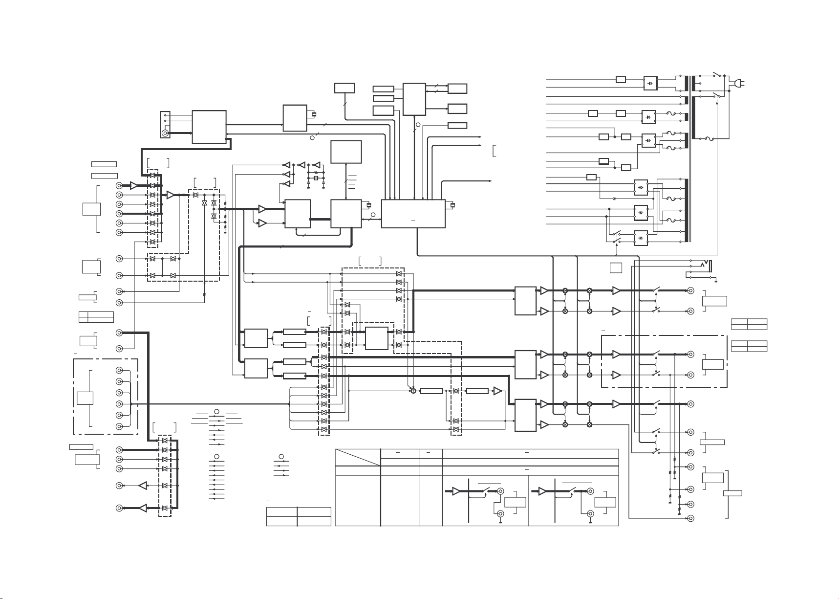
BLOCK DIAGRAM
6
1060VR/1070VR/KR-V8090/KR-V9090
Indicator tube
(11-MT-110GK)
Indicator tube driver
(uPD16311GC-AB6)
RDS
Signal level
RDS clock
RDS data
Key matrix
PLL IC
(LC72131)
Selector analog
switch control IC
(NJU7311/7312/7313)
Electron volume IC
(TC9412P/9413P)
Electron tone
control IC
(TC9184P)
Video selector IC
(SN761200N)
DSP
(56004)
Selector encoder A
Selector encoder B
Volume encoder A
Volume encoder B
CH SPACE
Remote controller
reception
SL16 / XS8
Serial BUSY
Serial DATA
SD
STEREO
RESET
CE
PROTECT
LOUDNESS
MUTE
-20dB ATT
RELAY POWER
RELAY A
RELAY B
RELAY CS
RELAY TR
(X08) IC28
u-COM
CXP82840-120Q(K,P,M)
CXP82852-107Q(E,T,Q)
MUTE LED
STANDBY LED
(X08) IC40
(X14) ED1
(X14)
(X05) IC2
(X08) IC2,12 (X09) IC3,4
(X08) IC5,7,9
(X08) IC13
(X08) IC1
(X08) IC26
(X14) IC1
11 16
4
9
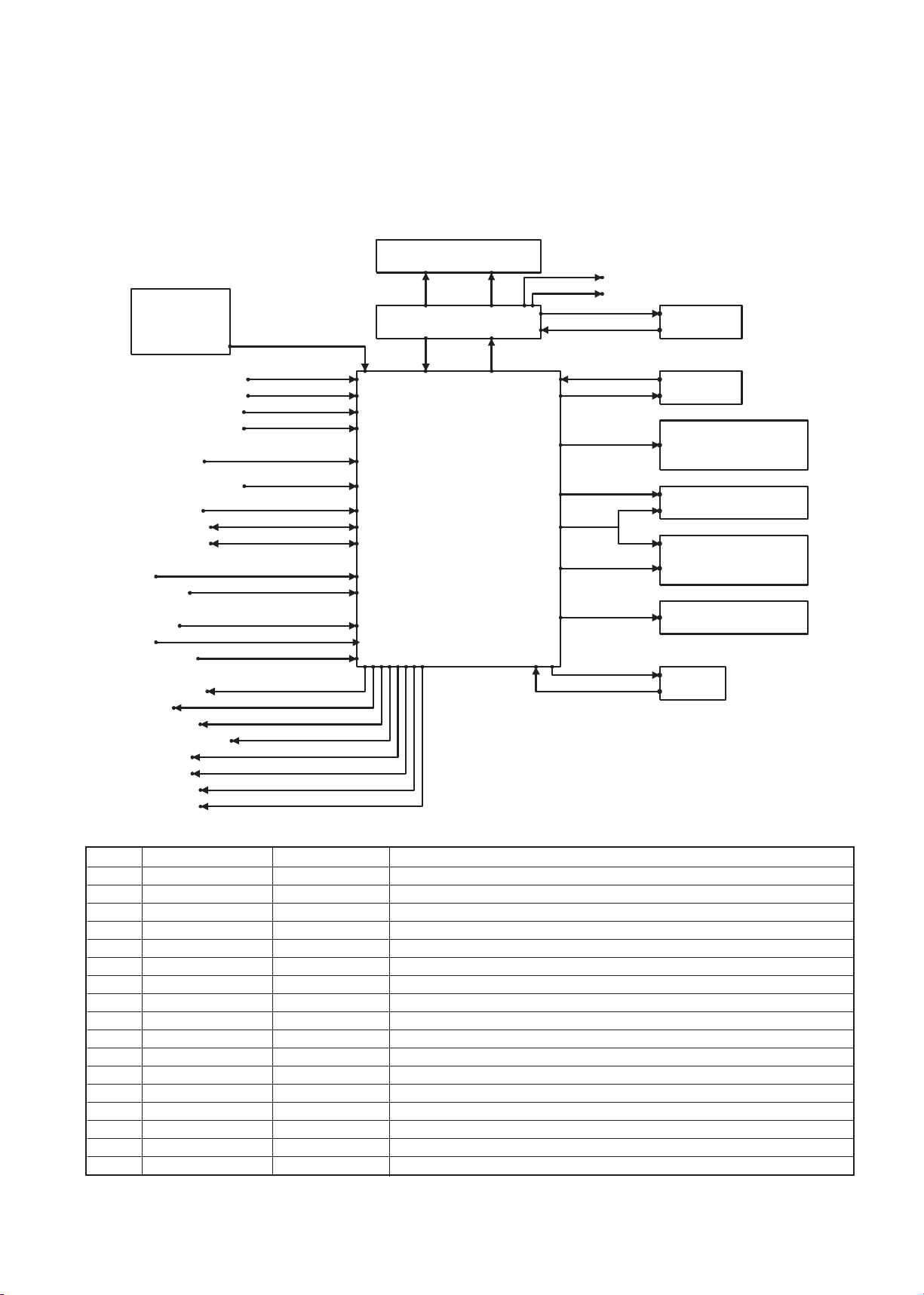
CIRCUIT DESCRIPTION
1. Microprocessor CXP82840-120Q/CXP82852-107Q(X08-, IC28)
1-1 Microprocessor periphery block diagram
No. Name I / O Description
1NC O
2NC O
3 NC – Connects to VDD
4 RDS CLK I RDS clock signal input
5 RDS DATA I RDS data signal input
6 VOL ENC A I Volume encoder A input
7 VOL ENC B I Volume encoder B input
8 REMOCON I Remote controller data input
9 CH SPACE I Tuner description switching input
10 NC –
11 NC –
12 SEL ENC A I Selector encoder A input
13 SEL ENC B I Selector encoder B input
14 PLL DO I PLL IF counting value input
15 PLL CE O LC72131 (PLL) strobe signal output
16 PLL CLK O LC72131 (PLL) clock signal output
17 PLL DATA O LC72131 (PLL) data signal output
1-2 Terminal explanation
7

1060VR/1070VR/KR-V8090/KR-V9090
8
CIRCUIT DESCRIPTION
No. Name I / O Description
18 T MUTE O Tuner mute signal output
19 STEREO O Tuner stereo signal input
20 SD I Tuner sd signal input
21 FL STB O uPD16311 (FL driver) strobe signal output
22 FL CLK O uPD16311 (FL driver) clock signal output
23 FL DOUT I uPD16311 (FL driver) data signal input
24 FL DIN O uPD16311 (FL driver) data signal output
25 DSP CLK – 56004 (DSP) clock signal output
26 DSP MIS0 I 56004 (DSP) data signal input
27 DSP MIS1 O 56004 (DSP) data signal output
28 – – A / D standard voltage (+5V)
29 S. LEVEL I RDS signal level input
30 DSP SS O 56004 (DSP) interface signal output
31 DSP HREQ I 56004 (DSP) host request signal input
32 SL16 / X58 I Serial SL16 / XS8 switching input
33 S BUSY I/O Serial busy signal input - output
34 S DATA I/O Serial data signal input - output
35 PROTECT I Protection signal input
36 CE I Microprocessor AC off signal input
37 – – Connects to VSS
38 RESET I Reset signal input
39 EXTAL – 8MHz oscillation elements (input)
40 XTAL – 8MHz oscillation elements (output)
41 VSS – Microprocessor power supply (GND)
42 TX – –
43 TEX – Connects to VSS
44 VDD – Microprocessor power supply (+5V)
45 VFDP – Connects to VSS
46 DSP RESET O 56004 (DSP) reset signal output
47 VIDEO D O SN761200n (video sel) control signal D output
48 VIDEO C O SN761200n (video sel) control signal C output
49 VIDEO B O SN761200n (video sel) control signal B output
50 VIDEO A O SN761200n (video sel) control signal A output
51 LOUDNESS O Loudness control signal output
52 -20dB ATT O Volume -20dB ATT control signal output
53 TON STB O TC9184P (Tone) strobe signal output
54 VOL STB O TC9184P(Volume) strobe signal output
55 VOL/TON CLK O TC9412P/9184P (Volume/Tone) clock signal output
56 VOL/TON DAT O TC9412P/9184P (Volume/Tone) data signal output
57 SEL STB2 O NJU7311 (for Sel AC-3) strobe signal output
58 SEL STB1 O NJU7313/7312/7311 (Sel) strobe signal output
59 SEL CLK O NJU7313/7312/7311 (Sel) clock signal output
60 SEL DATA O NJU7313/7312/7311 (Sel) data signal output
61 MUTE O Audio mute signal output
62 RELAY POWER O Power relay ON/OFF output
63 RELAY TR O 2nd side voltage relay ON/OFF output
64 RELAY CS O Speaker C/S relay ON/OFF output
65 RELAY B O Speaker B relay ON/OFF output
66 RELAY A O Speaker A relay ON/OFF output
67 DSP GPIO O
68-80 NC – 56004 (DSP) data forwarding control signal output
89 VDD O Microprocessor power supply (+5V)
90-100 NC O –

1060VR/1070VR/KR-V8090/KR-V9090
9
CIRCUIT DESCRIPTION
2. In order that an initial state and also back-up are done it functions.
2-1 clear of Back-up
Alternating current on, while pressing a remote power key of a panel/turn off.
Clearing the condition of back-up where is stored that moment, at present it, be set up to the initial state.
(1) Initialization of an amplifier function
Remote power...............................................................................................Power off
Selector source..............................................................................................Tuner
Selector preset ..............................................................................................No
Video output source.......................................................................................Video 1
Speaker A relay.............................................................................................On
Speaker B relay.............................................................................................OFF
Volume ..........................................................................................................Seven steps
Audio adjustment mode.................................................................................OFF
BASS.............................................................................................................0dB
TREBLE.........................................................................................................0dB
Input level......................................................................................................0dB
Loudness.......................................................................................................OFF
Source direct .................................................................................................OFF
Sub woofer Rch.............................................................................................OFF
(2) Initialization of a surround function
Surround mode..............................................................................................Stereo (surround off)
digital signal processor mode........................................................................Arena
Center mode..................................................................................................Normal
Distance.........................................................................................................OFF
Left level........................................................................................................20ms
Right level......................................................................................................0 step
Center level ...................................................................................................0 step
Rear level ......................................................................................................0 step
Sub woofer ....................................................................................................0 step
Effect level.....................................................................................................0 step
WALL.............................................................................................................3
Room size......................................................................................................Medium
(3) Initialization of a tuner function
Band..............................................................................................................Frequency modulation
Preset channel...............................................................................................--ch
Receiving frequency......................................................................................Most minimum value of each destination
K1/K2 type....................................................................................AM modulation : 530kHz
......................................................................................................FM modulation : 87.50MHz
E1/E2/Q type................................................................................AM modulation : 530kHz
......................................................................................................FM modulation : 87.50MHz
Auto/manual operation ..................................................................................Auto
Display mode.................................................................................................Indication of a frequency
RDS memory.................................................................................................OFF
EON interrupt receiving mode.......................................................................OFF
1060VR/1070VR/KR-V8090/KR-V9090
10
CIRCUIT DESCRIPTION
Channel
BAND
K1
BAND
K2
BAND
E1/E3
BANDQ01chFM87.50MHz
FM
87.50MHz
FM
87.50MHz
FM
87.50MHz
02chFM98.00MHz
FM
98.00MHz
FM
98.00MHz
FM
98.00MHz
03chFM108.00MHz
FM
108.00MHz
FM
108.00MHZ
FM
108.00MHZ
04chAM630kHz
AM
630kHz
AM
630kHz
AM
630kHz
05chAM1000kHz
AM
1000kHz
AM
999kHz
AM
999kHz
06chAM1440kHz
AM
1440kHz
AM
1440kHz
AM
1440kHz
07chFM87.50MHz
FM
87.50MHz
FM
87.50MHz
FML
74.00MHz
08chFM87.50MHz
FM
87.50MHz
FM
87.50MHz
FML
65.00MHz
09chFM87.50MHz
FM
87.50MHz
FM
87.50MHz
FML
69.00MHz
10chFM89.10MHz
FM
89.10MHz
FM
89.10MHz
FM
89.10MHz
11chFM90.00MHz
FM
90.00MHz
FM
90.00MHz
FM
90.00MHz
12chFM97.50MHz
FM
97.50MHz
FM
97.50MHz
FM
97.50MHz
13chFM98.50MHz
FM
98.50MHz
FM
98.50MHz
FM
98.50MHz
14chFM106.00MHz
FM
106.00MHz
FM
106.00MHz
FM
106.00MHz
15chAM530kHz
AM
530kHz
AM
531kHz
AM
531kHz
16chAM990kHz
AM
990kHz
AM
990kHz
AM
990kHz
17chAM1700kHz
AM
1610kHz
AM
1602kHz
AM
1602kHz
18chFM87.50MHz
FM
87.50MHz
FM
87.50MHz
FM
87.50MHz
19chFM87.50MHz
FM
87.50MHZ
FM
87.50MHz
FM
87.50MHz
20chFM87.50MHz
FM
87.50MHz
FM
87.50MHz
FM
87.50MHz
21~39chFM76.00MHz
FM
87.50MHz
FM
87.50MHz
FM
87.50MHz
3. TUNER PRESET MEMORY FREQUENCY(INITIALIZE)
The initial setting is performed in a following event :
1. When backup memory data is destroyed when reset is applied to the microprocessor.
2. When the power cord is plugged in to the AC wall outlet while pressing the POWER key.
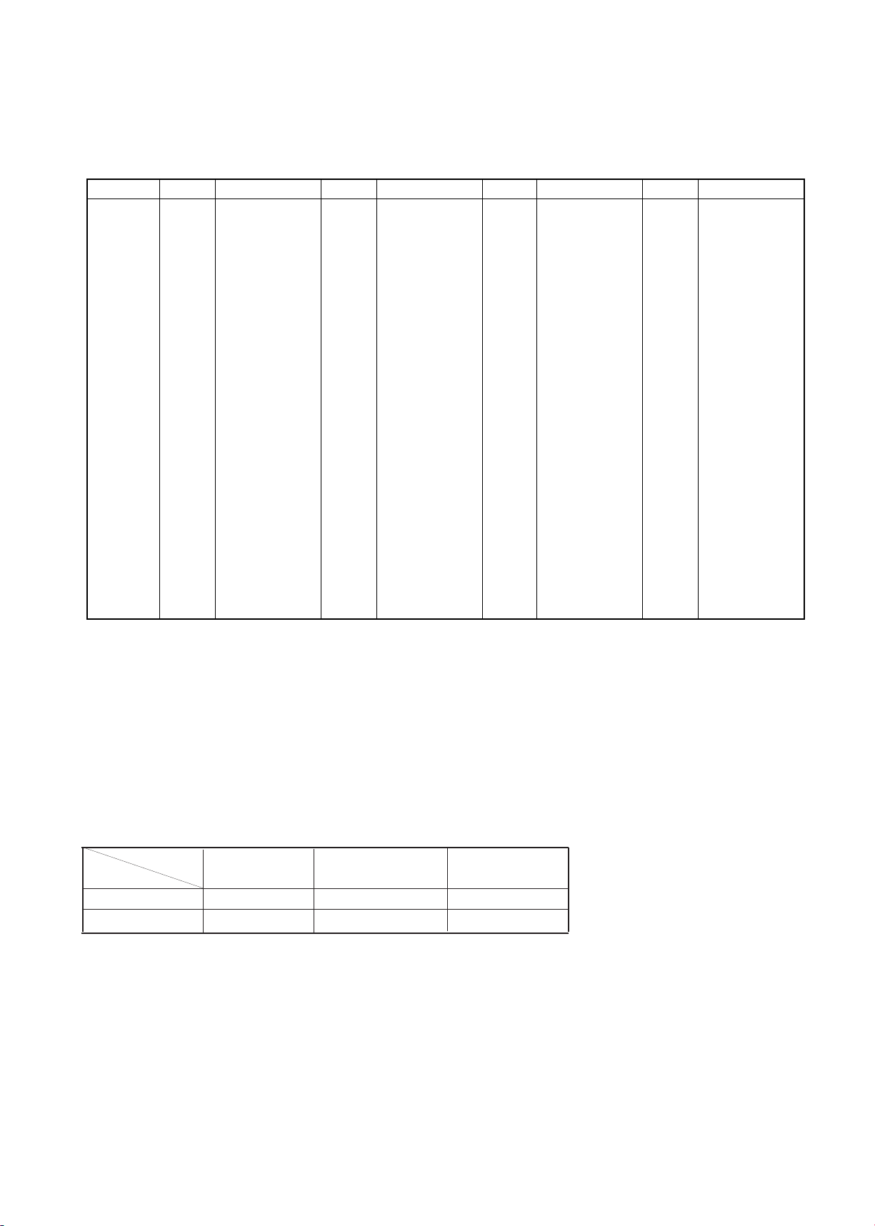
4. Mode / destination list
(1) KR-9090 / 8090 function judgement
Function list
Function
Model
AC-3
Rch L / R control
switching switch
4
SW4
KR-V9090 O different control 1
KR-V8090 X Simultaneous control 0
(2) Judgement of the destination
In this microprocessor the destination is switched by a diode switch.
The relation between a diode switch and destination are as under table.
1060VR/1070VR/KR-V8090/KR-V9090
11
CIRCUIT DESCRIPTION
Type Band
Range of a
receiving frequency
Channel
space
IF
Phase locked
loop standard
frequency
Destination switching switch
(X14) IC1
(X08) IC2
SW3 SW2 SW1
321
K1 FM 87.35MHz - 108.0MHz 100kHz +10.7MHz 25kHz
000
(1700) AM 530kHz - 1700kHz 10kHz +450kHz 10kHz
K2 FM 87.5MHz - 108.0MHz 100kHz +10.7MHz 25kHz
011
(1610) AM 530kHz - 1610kHz 10kHz +450kHz 10kHz
E1
FM 87.5MHz - 108.0MHz 50kHz +10.7MHz 25kHz
011
AM 531kHz - 1602kHz 9kHz +450kHz 9kHz
E3
(RDS )
FM 8735MHz - 108.0MHz 50kHz +10.7MHz 25kHz
101
AM 531kHz - 1602kHz 9kHz +450kHz 9kHz
Q (RDS)
FML 65.0MHz - 74.0MHz 10kHz +10.7MHz 5kHz
111FMH 87.5MHz - 108.0MHz 50kHz +10.7MHz 5kHz
AM 531kHz - 1602kHz 9kHz +450kHz 9kHz
✡ Diode switch (SWx) 0 = diode no (It becomes LOW input in the case that it is static)
(It becomes HIGH input in the case that it is static)
There is 1 = diode
X = transistor switch (0 = OFF / 1 = ON)
✡ A phase locked loop standard frequency is the value that set up it to a phase locked loop.
This value becomes same a dividing ratio of amplitude modulation with a phase locked loop standard frequency.
However, a dividing ratio of frequency modulation becomes 2 times of phase locked loop standard frequencies.
Control
integrated
circuit
SW
L/R
TUNER
PHONO
CD
TAPE/
MD
VIDEO 1
VIDEO 2
VIDEO3
AV AUX
NJU7312
SW1
2 L 01000000
27 R01000000
SW2
3 L00000010
26 R00000010
SW3
4 L00000100
25 R00000100
SW4
600001000
23 R00001000
SW5
7 L00010000
22 R00010000
SW6
8 L00100000
21 R00100000
SW7
10 L10000000
19 R10000000
SW8
11 L00000001
18 R00000001
5. Setting contents of a control integrated circuit
5-1 Condition of a selector switch
(X09-) IC3
The basis destination of a tuner
ch SP
9
1
1
0
1
1
1060VR/1070VR/KR-V8090/KR-V9090
12
CIRCUIT DESCRIPTION
Control
integrated
circuit
Condition
SW1
SW2
SW3
SW4
SW5
SW6
SW7
27 L
2 R
26 L
3 R
24 L
5 R
23 L
6 R
21 L
8 R
20 L
9 R
18 L
11 R
NJU7311
ch
LINE INPUT
*1
1100110011000
0
LINE INPUT
0011001100010
0
*1 Alternating current-3 modes use 5.1ch INPUT only at the time of alternating current-3 correspondence selectors
(DVD/1d) in on condition.
Use usual LINE INPUT at the time of except for the above.
Control
integrated
circuit
SW
L/R
TUNER
PHONO
CO
TAPE/
MD
VIDEO1
VIDEO2
VIDEO3
AV AUX
NJU7313
SW1
2 L11101111
27 R11101111
SW2
3 L11110111
26 R11110111
SW3
4 L11111111
25 R11111111
SW4
5 L00000000
24 R00000000
SW5
7 L*122 R
*1
SW6
8 L*121 R
*1
SW7
10 L*219 R
*2
SW8
11 L*218 R
*2
*1 Adapter on/off control *2 Control of INPUT LEVEL
Adapter on : SW4 (L/R) 0 INPUT LEVEL : 0dB SW7(L/R) -1
SW5 (L/R) 1 SW8(L/R) 0
Adapter off : SW4 (L/R) 1 INPUT LEVEL : -3dB SW7(L/R) 0
SW5 (L/R) 0 SW8(L/R) 0
(X09-)IC4
Control
integrated
circuit
Condition
SW1
SW2
SW3
SW4
SW5
SW6
SW7
27 L
2 R
26 L
3 R
24 L
5 R
23 L
6 R
21 L
8 R
20 L
9 R
18 L
11 R
NJU7311
SOURCE
DIRECT
0000001100010
0
STEREO
00111100000100DSP
11001100000100M. INPUT
11001100001000TEST TONE
0000000011001
1
(X08-) IC2
(X08-) IC2
only KR-V9090/1070VR
1060VR/1070VR/KR-V8090/KR-V9090
13
CIRCUIT DESCRIPTION
6. PLL IC expansion port control
PLL IC expansion port control list (Control data by software)
Phase locked loop integrated circuit expansion port control list (Logic that is outputted from a port [H / L H1-z]
Only L / HI-z is able to output the port of frequency modulation / amplitude
✽ 1 : modulation / LW / MONO due to Nch open drain.
✽
2 : HI-z is made constantly because there is not LW in the specification is this time.
Operating state
Extension port
name
10 7 8 9 11 13
FM AM LW MONO RDS ATT IF ON
IF ON
RDS ATT
ON
MONO ON
FM ON100110
AM ON010110
MONO OFF
FM ON100010
AM ON010010
RDS ATT
OFF
MONO ON
FM ON100100
AM ON010100
MONO OFF
FM ON100000
AM ON010000
IF OFF
RDS ATT
ON
MONO ON
FM ON100111
AM ON010111
MONO OFF
FM ON100011
AM ON010011
RDS ATT
OFF
MONO ON
FM ON100101
AM ON010101
MONO OFF
FM ON100001
AM ON010001
Operating state
Extension port
name
10 7 8 9 11 13
FM AM LW MONO RDS ATT IF ON
IF ON
RDS ATT
ON
MONO ON
FM ON L HI-z HI-z L H L
AM ON HI-z L HI-z L H L
MONO OFF
FM ON L HI-z HI-z HI-z H L
AM ON HI-z L HI-z HI-z H L
RDS ATT
OFF
MONO ON
FM ON L HI-z HI-z L L L
AM ON HI-z L HI-z L L L
MONO OFF
FM ON L HI-z HI-z HI-z L L
AM ON HI-z L HI-z HI-z L L
IF OFF
RDS ATT
ON
MONO ON
FM ON L HI-z HI-z L H H
AM ON HI-z L HI-z L H H
MONO OFF
FM ON L HI-z HI-z HI-z H H
AM ON HI-z L HI-z HI-z H H
RDS ATT
OFF
MONO ON
FM ON L HI-z HI-z L L H
AM ON HI-z L HI-z L L H
MONO OFF
FM ON L HI-z HI-z HI-z L H
AM ON HI-z L HI-z HI-z L H
1060VR/1070VR/KR-V8090/KR-V9090
14
CIRCUIT DESCRIPTION
7. Test mode
(1) Test mode setting method
Turn on the power supply while pressing TUNINGDOWN key, to make a set in test mode condition.
When a set is set up in test mode condition a set
becomes the following condition.
Automatic POWER ON
All indicator tubes and also LED are lighted. (This
condition can be canceled by pressing the key of the
set.)
A backup at the thing except ON/OFF of POWER is
initialized.
(2) Test mode cancellation method
The power supply is turned off.
"Usually display / All the turn-off" is periodically repeated
by operating MEMORY key.
(3) A tuner function.
When a selector is set to the tuner, the following key is
not usual function and operates by the special function.
The function to summon the channel of the presetting
1
The following channel is summoned when not
operating +10 keys.
1ch~9ch (1~9key)
10ch (0key)
2
When +10 keys are pressed once, the following
channel is summoned.
11ch~19ch (1~9key)
20ch (0key)
3
When +10 keys are pressed twice, the following
channel is summoned.
21ch~29ch (1~9key)
30ch (0key)
4
When +10 keys are pressed three times, the following
channel is summoned.
31ch~39ch (1~9key)
40ch (0key)
5
When +10 keys are pressed four times, it gets to do
the function which is the same as the condition which
doesn’t press +10 keys.
• The S level hexadecimal DATA display and the
ATT ON/OFF function
When a selector is set to the tuner, it repeats the
following operation cyclically when operating the
PTY key of the set.
a) When ATT is in the OFF condition, it displays
as follows.
“ATT OFF display” + “Signal level display by
the tuner (HEX DATA)”
b) When ATT is in the ON condition, it displays as
follows.
“ATT ON display” + “Signal level display by
the tuner (HEX DATA)”
c) At the time of the ATT OFF condition, the set
becomes usual display.
✰ When the key of a set is pressed a signal level
display of a tuner continues to display the value of
when that ATT works.
• MUTE signal output
Because TUNER-MUTE always becomes OFF
condition, it isn’t possible to do control.
• When a selector is set to the thing except TUNER,
each key does usual function.
Then, the test mode doesn't work.
• RDS display mode.
RDS-PS display works by pressing PRO-LOGIC
key irrespective of TUNED. (It is able to cancel it
by pressing PRO-LOGIC key.)
• I
(4) An amplifier function.
• The value in the first of the speaker setting by the test
mode is full equipment.
• When a selector is set to the thing except TUNER, the
following key works by the special function.
When a selector is set to TUNER, the following key
does usual work.
• The way of setting MAX/MID/MID of AUDIO
LEVEL/SURROUND LEVEL easily.
• AUDIO LEVEL/SURROUND LEVEL is variably made
of MULTILEVEL UP/DOWN operation. When a
selector is set to the thing except TUNER, operate a
number key. MAX/MID/MIN can be set by the
following operation.
It is set in as follows at the time of MID.
Master volume Intial value
Balance Center
BASS/TREBLE/SUB WOOFER/ 0dB or a 0step
CENTER/REAR
EFFECT 1step
1
It is possible to set as follows by operating with the
number key when a selector is set to the thing except
TUNER.
2
The way of setting AUDIO LEVEL/SURROUND
LEVEL easily.
Setting item
Ten-key that
operates
Master volume
Maximum
2
0dB
Middle
3
-30dB
Minimum
1
-98dB
Item
Number key
INPUT LEVEL
4
"Press number
key ""1-3"",
after a number
key of the left
description is
pressed."
DISTANCE(PRO LOGIC only)
5
Lch LEVEL
6
Rch LEVEL
7
CENTER LEVEL
8
Sch LEVEL(CYCLIC SL ←→ SR)
9
EFFECT(DSP only)
0
SUB WOOFER LEVEL
10
ROOM SIZE(DSP only)
MUTE
WALL SIZE(DSP only)
DIMMER

1060VR/1070VR/KR-V8090/KR-V9090
15
CIRCUIT DESCRIPTION
3 Test tone operation
While displaying as follows every time it presses
DIRECT key when dolby surround is working, it
switches a speaker and TEST-TONE is output.
By pressing DIRECT key, this work and dolby
surround can be canceled.
4
Mute signal output
Because the analog mute always becomes OFF
condition, it isn’t possible to control absolutely.
however, when the value with front volume is the
minimum, it becomes an analog mute ON condition.
5 AC-3 The 6ch input changing.(Only KR-V9090)
When the selector of KR-V9090 is VIDEO2, press
"AUTO/MANU" key. At this time, KR-V9090 becomes
"AC3 6ch input" condition. (M-INPUT is lighted).
"AC3 6ch input" condition is able to cancel by
pressing "AUTO/MANU" key. (It become usual
function).
6 The ADAPTER input changing.
Press the "BAND" key of KR-V9090. At this time, KRV9090 changes to ADAPTER input. When "BAND"
key is pushed again, it is able to cancel it.
7 TONE BASS/TREBLE
When KR-V9090 is doing the function of the test
mode, the TONE BASS/TREBLE key does a function
below periodically.
FLAT(0) MAX(+10) MIN(-10)
 Loading...