

Page 1
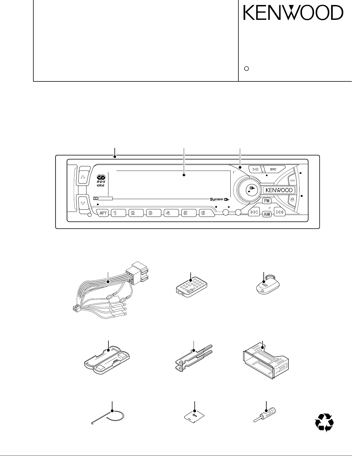
KRC-V879R
K3i
B NRLOUD SCAN REP MTL/M.RDM
AUD
PROG
/PTY
DAB
ANG
MENU
CLK
PWR OFF
47Wx4
DOLBY B NR
B.S/RDM
DISP
NAME.S
TI
VOL ADJ
EX
KRC-V879R /RY
M&T CASSETTE RECEIVER
SERVICE MANUAL
C
2001-2 PRINTED IN KOREA
B51-7748-00 (K) 1940
The CASSETTE MECHANISM OPERATION DESCRIPTION is the same model D40-1122-05.
Please refer to the service manual for model D40-1122-05(B51-7452-00).
DC cord
(E30-4942-05)
Remote com. assy
(A70-2015-15)
Remote com. assy
(A70-0886-15)
Antenna adaptor
(T90-0523-05)
Screw set
(N99-1704-05)
Torsion coil spring
(G01-2924-04)
Lever
(D10-4562-04)x2
Mounting hardware assy
(J21-9716-03)
Plastic cabinet assy
(A02-1497-03)
Front glass
(B10-3241-01)
Escutcheon assy
(B07-3007-03)
Panel assy
(A64-2135-02)
CA-R66
MASK-key
40%
Page 2
2
AUDIO
S-METER
AFC
IFC OUT
PLL DATA
PLL CLK
SW5V
FM
AM
TAPE
CHANGER
S METER
QUAL
SDA
SCK
S MUTE
A 8V
MODE 2
SUB-
MOT+B
SUB+
MODE 1
MS MODE
F/R
MUTE
MTL ON/OFF
BOLBY B/C
DOLBY ON/OFF
MS OUT
R REEL
F REEL
MODE 3
PACK IN
SRM SW2
SRM SW1
RCLK
QUAL
RDATA
NOISE
S METER
AFC
IFC OUT
PLL DATA
PLL CLK
MS OUT
MTL ON/OFF
MODE 2
MODE 3
R REEL
MODE 1
F REEL
MS MODE
F/R
MUTE
DOLBY ON/OFF
DATA C
CH RST
CH MUTE
DOLBY B/C
DATA H
CH CON
CH CLK
REQ H
REQ C
PACK IN
SRM SW3
SRM DET
RESET
SUB MOT2
SUB MOT1
SUB MOT3
CASS/SRM
MOTOR
ILL ON
AM+B
FM+B
SCK
SDA
PRE MUTE
MUTE
BEEP
P MUTE
ACC DET
PHONE
DIMMER
EXT AMP CONT
P CON
PAN5V
P ON
ANT CONT
B.U DET
SW5V
SW5V
2
3
3
13
CH MUTE
CH RST
DATA H
DATA C
CH CON
REQ C
CH CLK
REQ H
BACK UP
8
1200mV
440mV
A 8V
SW5V
PANEL5V
PANEL5V
4
B.U.5V
PANEL5V
FL+B
FAC
4
2
SUB+
SUB-
2
SUB-
SUB+
SDA
SCK
MOT+B
FOR VFD
A8V
+B
-B
FOR 4.5V PRE
PAN5V
B.U.5VSW5V
MUTE
AUX IN
BACK UP
SW5V
B.U.5V
B.U.5V +B
-B
CH
FM
1800mVTAPE
AM
3600mV
855mV
1372mV
600mV
3600mV
1800mV
E TYPE K TYPE
1800mV
2250mV
1715mV
4500mV
1069mVAM
CH
TAPE
FM
E TYPE
ILL
TEL MUTE
ACC
ANT CON
P CON
BACK UP
EXT.AMP CONT
F/E
FM+B
BUFFER
NOISE
BUFFER
DECODER
RDS
IC11
Q73
IC2
E-VOL
MPX
N.C.
AM+B
CASSETTE MECH
SYSTEM U-COM
IC1
CD-CHANGER
MD-CHANGER
KEY
MATRIX
RESET
SW
LCD
DRIVER
REMO
G/R SW
RESET
IC15
X13-996/999
SYSTEM u-COM LCD TYPE
IC1
U-COMMATRIX
SW
RESET
LCD
IC1
X13-995/998
KEY
REMO
PANEL
G/R SW
V-ILL TYPE
LCD
DRIVER
IC2
VFD(GRADATED)
SW
RESET
X13-994/997
REMO
MATRIX
KEY
G/R SW
U-COM
IC1
PANEL
FL(GRADATED) TYPE
ROM
SPEANA
BPF
DRIVER
SUB MOT
IC13
E S
SYSTEM
IC5,ONLY FL MODEL
MAIN MOT
+B
SUB MOT
+B
Q42
Q37,38
DC/DC
A1 ONLY FL MODEL
Q33,34
ILL AVR
ONLY FL MODEL
DC/DC
A 8V
Q20
IC6
SW14V
Q36
EXT AMP CONT
DIMMER
ACC DET
TEL MUTE
P CON
B.U DET
ANT CON
Q39
Q32
Q25
Q26
Q28
Q24
SW5V B.U.5V
PAN5V
Q45
Q23 Q21,22
SRM
MECH
POWER IC
THEMO
PROTECT
IC4
IC10
MUTE LOGIC
DRIVER
MUTE
Q1-6 ONLY FL MODEL
4.5V
PRE AMP
IC7-9
SP OUT
1.8V PRE OUT
4.5V PRE OUT
LCD
251mV(ETYPE)
470mV(KTYPE)
FM:
AM:
230mV
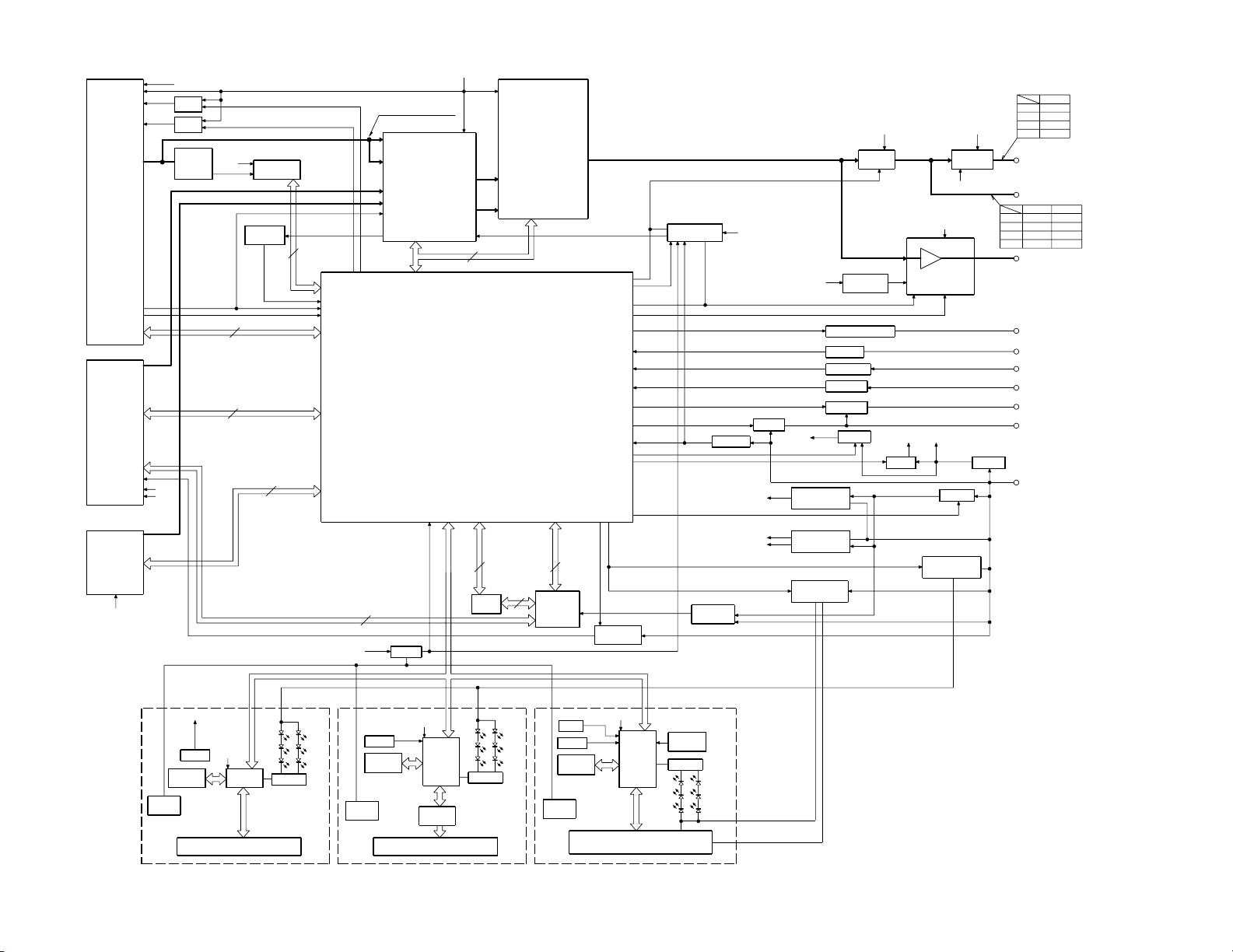
KRC-V879R/RY
KRC-V879R/RY
BLOCK DIAGRAM
Page 3
KRC-V879R/RY
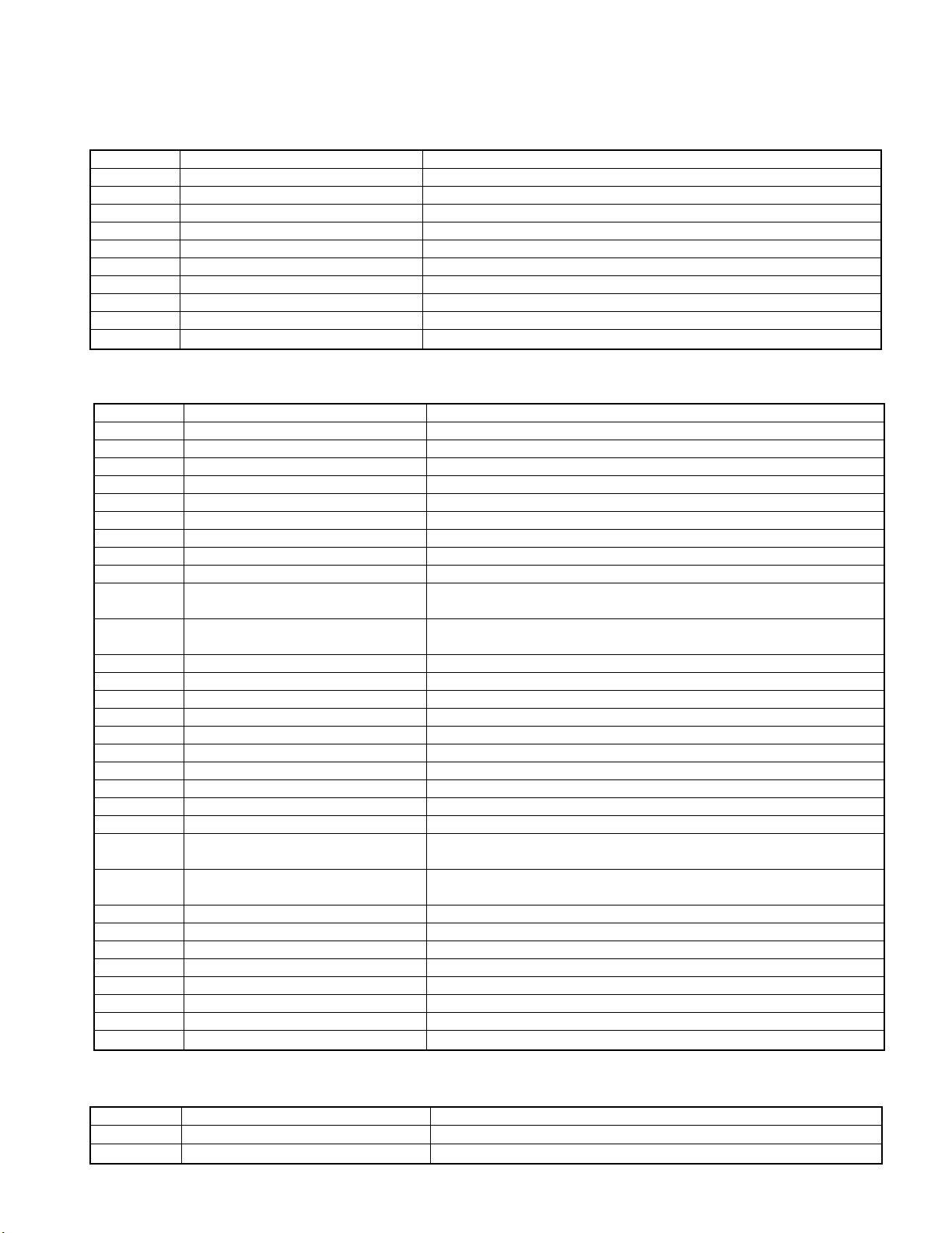
COMPONENT DESCRIPTION
(X13-9950-11)
(X13-9982-72)
Component Purpose • Function Operation • Conditions • Compatibility
IC1 Panel u-CON
IC2 LCD Driver
IC3 Remocon IC
Q1 V
Q2 Key Illumination (Red) SW ON when the base goes "H".
Q3 Key Illumination (Green) SW ON when the base goes "H".
Q4 Remocon IC supply SW ON when the base goes "L".
Q5 Illumination (Red) SW ON when the base goes "H".
Q6 Illumination (Green) SW ON when the base goes "H".
Q7 Illumination (Blue) SW ON when the base goes "H".
(X14-6442-70)
(X14-6452-72)
Component Purpose • Function Operation • Conditions • Compatibility
IC1 System u-com
IC2 E-VOL, N.C, MPX
IC3 Regulator IC for Audio 8V
IC4 Power IC
IC10 Mute logic IC
IC11 RDS decoder
IC13 Motor driver IC
IC15 Reset IC
Q1~4 PRE OUT MUTE SW Pre outs are muted when the base goes "H".
Q18~20 Audio 8V AVR
Q21, 22 B.U 5V AVR
Q23 SW 5V ON when the base goes "L".
Q24 B.U detection ON when the base goes "H" during B.U applied.
Q25 ACC detection ON when the base goes "H" during ACC applied.
Q26, 27 P-ANT SW Q26 is turned ON when Q27's base goes "H".
Q28~31 P-CON SW Q28 is turned ON when Q31's base goes "H".
Q32 Dimmer SW ON when the base goes "H" while vehicle small lamps turn on.
Q33, 34, 44 Illumination AVR ON when Q44's base goes "H".
Q36 SW 14V ON when base goes "H".
Q37, 38 Motor driver supply Q38 is turned ON when Q37's base goes "H".
Q39 External Amp Control ON when the base goes "L".
Q41, 42
Q43 Motor driver's voltage SW
Q45, 46 Panel 5V SW Q45 is turned ON when Q46's base goes "H".
Q71 Pre out mute driver ON when the base goes "L".
Q72 E-VOL Mute SW ON when the base goes "H".
Q73 Noise buffer
Q85 IFC out buffer
Q86, 88 AM+B SW Q88 is turned ON when Q86's base goes "H".
Q87, 89 FM+B SW Q89 is turned ON when Q87's base goes "H".
Q90 Composite out buffer
AVR ON when the base goes 9.1V during ILL+B applied.
LCD
Inverted darlington connection
Q20 is turned ON when Q18's base goes "H".
Inverted darlington connection
Q22 is turned ON when Q21's base goes "H".
Cassette mecha main motor
supply SW
Q42 is turned ON when Q41's base goes "H".
Base "H" ··· cassette mecha's submotor
Base "L" ··· mask mecha's motor.
(X87-3022-71)
(X87-3032-73)
Component Purpose • Function Operation • Conditions • Compatibility
IC1 Playback EQ, Dolby & Blank Detection
Q1 Constant Switching in Blank Detection Switches the time constant according to the PLAY or FF/REW mode.
3
Page 4

KRC-V879R/RY
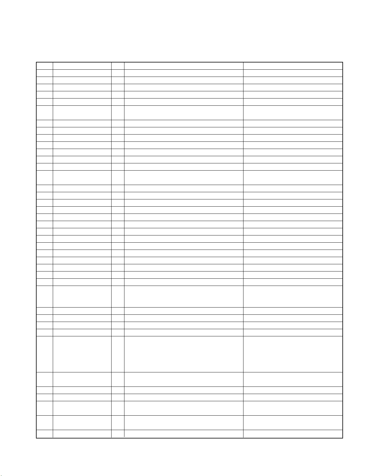
MICROCOMPUTER'S TERMINAL DESCRIPTION
UPD703033GC049 (IC1: X14)
SYSTEM MICROCOMPUTER
Pin Name I/O Purpose Operation Description
1 AM+B O AM power supply terminal. During AM operation: H
2 FM+B O FM power supply terminal.
3 AFS O Constant switching when noise is detected.
4 PLL-DATA I/O DATA input/output terminal from/to F/E.
5 PLL-CLK I/O CLOCK input/output terminal from/to F/E.
6 Evdd - Positive power supply terminal.
7 GND - Grounding terminal.
8 N.C O No connection.
9 BEEP O Beep output terminal.
10 REMO I Remote control input terminal.
11 P-ON O SW 14 V control terminal. Power ON: H, Power OFF: L
12 P-STBY O Power IC STBY terminal control.
13 IC2-SDA I/O IC2 DATA line.
14 IC2-SCK O IC2 CLOCK line.
15 P-MUTE O Power IC muting terminal.
16 PRE-MUTE O Pre-Out muting terminal. During momentary power down: L
17
18 TEST - Test pin.
19 P-CON O Power control terminal. Power ON: H, Power OFF: L
20 ANT-CON O Antenna control terminal. TUNER, TI ON: H
21 MUTE O Muting terminal.
22 N.C O No connection.
23 ACC-DET I Acc detection terminal. Acc detected: L, Acc not detected: H
24 DIMMER I Small detection terminal. ON: L, OFF: H
25 SW-5V O 5 V power supply terminal. ON: L, OFF: H
26 CH-MUTE I Muting request from CH. ON: H, OFF: L
27 CH-CON O CH control output. ON: H, OFF: L
28 CH-REQH O Request output to CH. Requested: L
29 CH-RST O Reset output to CH.
30 EXT-AMP-CONT O External amplifier control terminal (In 200 ms). L 70 ms: Bass boost LOW
31 RESET I Reset input terminal Normal: H, Reset: L
32 XT1 I Sub-clock connection terminal.
33 XT2 - Sub-clock connection terminal.
34 REGC -
35 X2 - Main clock connection terminal. Power OFF or momentary power
SC CON Panel u-COM control. P-ON: H
Output terminal for the capacitor in the
regulator in u-COM.
During FM operation: H
Last FM with RDS model: H
During FM seek or AF search: L
During reception: H
Power IC OFF: L, Power IC ON: H
During reset: Input
Power OFF: L, All OFF: L
During TEL muting: L
ON: Open, OFF: L
The time constant is 0.48 ms with all
models.
Normal: L. When the system is
reset,turns H then L in 400 ms after
recovery from reset.
L 40 ms: Bass boost OFF
L 100 ms: Bass boost HIGH
The clock count is active even when
Power is OFF.
Power ON: Oscillated
down: Oscillation stopped
4
Page 5
KRC-V879R/RY
MICROCOMPUTER'S TERMINAL DESCRIPTION
UPD703033GC049 (IC1: X14)
SYSTEM MICROCOMPUTER
Pin Name I/O Purpose Operation Description
36 X1 I Main clock connection terminal.
37 Vss - Grounding terminal.
38 Vdd - Positive power supply terminal.
39 CLKOUT O Internal System Clock output.
40 N.C O No connection.
41 MOTOR O
42 MODE3 I Cassette mechanism mode detection terminal.
43 MODE1 I Cassette mechanism mode detection terminal.
44 MODE2 I Cassette mechanism mode detection terminal.
45 N.C O Outputs Low. No connection.
46 SUB1 O Sub-motor output terminal (1).
47 SUB2 O Sub-motor output terminal (2).
48 SUB3 O Sub-motor output terminal (3).
49 CAS/SRM O
50 N.C O Outputs Low. No connection.
51 N.C O Outputs Low. No connection.
52 ILL-ON O FL +B output terminal. ON: H, OFF: L
53 PAN-5V O Panel 5 V control terminal.
54 N.C O Outputs Low. No connection.
55 BVdd - Positive power supply terminal.
56 BVss - Grounding terminal.
57 N.C No connection.
58 N.C No connection.
59 N.C O Outputs Low. No connection.
60 N.C O Outputs Low. No connection.
61 ST TYPE1 I IC2 destination type terminal. Default: L
62 ST TYPE0 I IC2 destination type terminal. Default: L
63 SRM-SW1 I Panel position detection switch 1.
64 PAN-RESET O Reset output to Panel u-COM. Momentary power down: L
65 MC-REQ/PANEL REQ terminal for panel and u-COM. Panel detected: L
66 SRM-SW3 I Panel position detection switch 3.
67 SRM-SW2 I Panel position detection switch 2.
68 FWD/REV O TAPE EQ input switching terminal. FWD: L, REW: H
69 MS-CONT I/O TAPE input: L
70 AVCONT O AD reference voltage control output.
71 Avdd - Positive power supply terminal.
72 Avss - Grounding terminal.
73 Avref I
74 PHONE I PHONE detection terminal.
75 R-REEL I Cassette mechanism reel pulse input (REV). Vth = 2.5 V
Cassette mechanism main motor When the motor is running: H
output terminal. When it is stopped: L
Cassette mechanism/SRM mechanism Cassette mechanism: H
voltage switching terminal. SRM mechanism: L
Normal: H, Reset: L, Panel detached: L
Microcomputer overrun: L
During TAPE PLAY: H
Constant switching terminal in case
of blank detection.
Reference voltage supply terminal for
A/D converter.
During TAPE FF/REW or other than
Cassette mechanism detected: L
Cassette mechanism not detected: H
Same timing as P-ON. H during
operation.
TEL MUTE: No more than 1 V
NAVI MUTE: 2.5 V or more
5
Page 6

KRC-V879R/RY
MICROCOMPUTER'S TERMINAL DESCRIPTION
UPD703033GC049 (IC1: X14)
SYSTEM MICROCOMPUTER
Pin Name I/O Purpose Operation Description
76 F-REEL I Cassette mechanism reel pulse input (FWD). Vth = 2.5 V
77 N.C I No connection. Connected to GND
78 SRM-DET I SRM mechanism detection. SRM mechanism detected: L
79 NOISE I FM noise detection terminal. Model without RDS: Connected to GND
80 S-METER I Signal meter detection terminal.
81 R-DATA I RDS decoder DATA input terminal.
82 R-QUAL I RDS decoder QUAL input terminal.
83 IFC-OUT I F/E IFC OUT input terminal. Station detected: L
84 MUSIC I Music blank detection input.
85 PACK-DET I Cassette mechanism pack detection terminal.
86 DOLBY O Dolby ON/OFF switching. ON: H, OFF: L
87 R-CLK I RDS decoder CLK input terminal.
88 CH-REQC I Request input from CH. ON: L
89 SC-REQ Communication request from Panel u-COM.
90 N.C I No connection. Connected to GND.
91 EQ-MUTE O EQ muting switching.
92 MTL O NORMAL/METAL switching. NORMAL: H, METAL: L
93 BU-DET I Momentary power down detection terminal.
94 CH-DATAC I DATA input terminal from CH.
95 CH-DATAH O DATA output terminal to CH.
96 CH-CLK I/O CLOCK input/output terminal from/to CH.
97 SC-DATA DATA line from Panel u-COM.
98 MC-DATA DATA line to Panel u-COM.
99 MC-CLK CLK line to Panel u-COM.
100 N.C O Outputs Low. No connection.
Model without RDS and
RBDS: Connected to GND
Model without RDS
and RBDS: Connected to GND
Music signal detected: L
Music signal not detected: H
Cassette pack detected: L
Cassette pack not detected: H
Model without RDS and
RBDS: Connected to GND
During TAPE PLAY: L
During TAPE FF/REW: H
Other than TAPE input: H
Back-Up detected: L
Back-Up not detected
(momentary power down): H
6
Page 7

KRC-V879R/RY
MICROCOMPUTER'S TERMINAL DESCRIPTION
UPD780076GK501 (IC1: X13)
Panel MicroComputer
Pin Name I/O Purpose
1 REMO_ON O Remote control 5 V switching.
2 RED O 2-color LED switching.
3 GREEN O 2-color LED switching.
4 KR5-1 I Key return port.
9 Vss - -
10 VDD_0 - -
11-14 KS4-1 O Key scan port.
15 MC_DATA I DATA input port from system u-COM.
16 SC_DATA I/O DATA output port from Panel u-COM.
17 MC_CLK I CLK input port from system u-COM.
18 L_CE O Enable output port to LCD driver.
19 L_DATA O DATA output port to LCD driver.
20 L_CLK O CLK output port to LCD driver.
21 NC O 22 TYPE I Destination type switching port.
23 L_INH O Display ON/OFF output port to LCD driver.
24 Vdd_1 - 25 AVss - -
26-33 N.C. I No connection (Fixed at GND).
34 AVref - Connected to GND.
35 NC O No connection (Open and outputs Low).
36 RESET I Reset port.
37 XT2 - Open.
38 XT1 I Pulled up to VDD.
39 TEST I Flash u-COM rewrite port (normally Low).
40 X2 - Main system clock.
41 X1 I Main system clock.
42 Vss1 - 43 MC REQ I Request input port from system u-COM.
44 SC_CON I Panel u-COM ON/OFF port.
45 SRC I SRC detection.
46 OPEN-EJECT I Interrupt port for OPEN/EJECT keys.
47 CONT_G O Switching output port to variable illumination. (Green)
48 SC_REQ O Request input port from Panel u-COM.
49 NC O
50 CONT_B O Switching output port to variable illumination. (Blue)
51 N.C. O No connection.
52 CONT_R O Switching output port for variable illumination. (Red)
53 EJECT I Ejection detection port.
54-64 N.C. O No connection.
7
Page 8

KRC-V879R/RY
TEST MODE
M&T-SRT 2001 Model Test Mode
1. How to enter the test mode
• While holding the FM and Preset 6 keys, reset the unit.
2. How to exit from the test mode
• While holding the Preset 6 key, reset the unit.
• (Note) The test mode cannot be terminated by Acc OFF,
power OFF or momentary power down.
3. Initial status in the test mode
• Sources: All OFF.
• Display: All segments are lit.
• Volume: -10 dB (displayed as 30)
• Loudness: OFF
• CRSC: OFF regardless of the presence of switching
function.
• SYSTEM Q: Flat.
• Blank Skip: OFF. (C/R model)
• LED: White for no scanning. (VLCD model)
4. Special display in Tuner mode
• When any of the following messages is displayed in
Tuner mode, the front end may be abnormal.
• "TNE 2P NG": The EEPROM is set to the default (unstable values) because the F/E was shipped without passing
through the adjustment process, etc.
• "TNCON NG": Communication with the F/E is not possible.
5. Forced switching of K3I
• Each press of the Preset 6 key in Tuner mode should
switch K3I from AUTO î Forced Wide î Forced Middle
î Forced Narrow î AUTO. The initial status is AUTO
and the display shows these modes as follows.
• AUTO : FMA
• Forced Wide : FMW
• Forced Middle : FMM
• Forced Narrow : FMN
6. Test mode specifications of the CD receiver
• Forced ejection is inhibited in the reset start operation.
When the unit is reset while a CD is loaded in it, the CD
is not recognized by resetting.
• Each press of the Track Up key jumps to the following
track numbers.
No. 9 î No. 15 î No. 10 î No. 11 î No. 12 î No. 13
î No. 14 î No. 9 (The cycle restarts from here.)
• Each press of the Track Down key jumps to the previous
track number to the track being played.
7. Audio-related specifications
• A short press of the Q key initiates the audio adjustment
mode.
• Pressing the ✽ key on the remote initiates the audio
adjustment mode.
• Continuous holding of a remote control key is inhibited.
• Bass, Middle and Treble are adjusted in 3 steps of
Min/Center/Max with the Track Up/Down keys.
• Balance is adjusted in 3 steps of Left Max/Center/Right
Max with the Track Up/Down keys.
• Fader is adjusted in 3 steps of Rear Max/Center/Front
Max with the Track Up/Down keys.
• HPF is adjusted in 2 steps of Through/220 Hz with the
Track Up/Down keys.
• LPF is adjusted in 2 steps of Through/120 Hz with the
Track Up/Down keys.
• Bass f, Bass Q, Bass EXT, Middle f, Middle Q and Treble
f are not dealt with by the audio adjustment.
8. Menu-related specifications
• A short press of the CLK key initiates the Menu mode.
• Pressing the DNPP/SBF key on the remote initiates the
Menu mode.
• Continuous holding of a remote control key is inhibited.
• Calendar adjustment, calendar display switching and calendar memo are eliminated from the targets of continuous key holding. (FL model).
• In the color adjustment mode, pressing the Preset 1 key
sets Red, 2 sets Blue, 3 sets Green and 4 sets Green.
(VLCD model)
• Contrast is adjusted in 3 steps of 0/5/10 and the default
is 5. (VLCD/LCD model)
• Brightness is adjusted in 3 steps of 0/5/10 and the default
is 10. (Normal FL model)
9. Backup current measurement
• When the unit is reset while Acc is OFF (i.e. by turning
Back-Up ON), the MUTE terminal goes OFF in 2 seconds in place of 15 second. (The panel, CD mechanism
and TAPE mechanism are not activated at this time.)
8
Page 9
KRC-V879R/RY
TEST MODE
10. Special display when the display is All ON
Pressing the Preset keys while the power is All OFF displays the following information.
Version display
(8 digits, Month/Day/Hour/Minute)
PRESET1 (Display)
SYS xxxxxxxx System microcomputer
PAN xxxxxxxx Panel microcomputer
PRESET2
PRESET3 Long press/hold: Clear power ON time.
PRESET4
PRESET5 Long press/hold: Clear TAPE/CD/MD ejection
PRESET6 Long press/hold: Clear Panel open/close count.
Serial No. display (8 digits)
(Note) CD/R K type eXcelon model
(Display) SNo. xxxxxxxx
Short press: View power ON time.
(The All OFF period is not counted.)
(Display)
PonTim xxxxx Max. 65535 (hours)
Short press: Display TAPE/CD/
MD operation time.
Long press/hold: Clear TAPE/CD/MD operation
time. (Display)
CDTime xxxxx (CD/R)
TapTim xxxxx (C/R) Max. 65535 (hours)
Short press: Display TAPE/CD/
MD ejection count.
count. (Display)
EjeTim xxxxx Max. 65535 (times)
Short press: Display Panel open/close count.
(Display)
PnCnt xxxxx Max. 655350 (times)
11. Other specifications
• Automatic panel closing when a tape/CD is inserted is
inhibited. (M&T model)
• Panel operation by turning power OFF/ON is inhibited.
(M&T model)
• Pressing the ATT key opens or closes the panel. (M&T
model)
• Messages such as "CODE OFF" are not displayed when
power is turned ON.
• Pressing the TI (AUTO) key during changer operation
turns 2zone ON. 2zone can be turned OFF by pressing
the TI (AUTO) key again. The P/S dot lights while 2zone
is ON.
• Pressing and holding the CLK key for a second in the All
OFF status the Mask Key (security) write mode.
7 Security-related information
• Forced Power ON mode (All models)
Even when the security (Mask key) is approved, resetting the unit while holding the ATT and Preset 4 keys
makes it possible to turn the power ON for 30 minutes.
After 30 minutes have elapsed, it is not possible to return
to the previous condition unless the unit is reset again.
• Method of registration of the security code after
EEPROM (Tuner Unit Ass'y) replacement (Code
security model)
1. Enter the test mode. (See 1 How to enter the test
mode)
2. Press the CLK key to enter the security registration
mode.
3. Enter the code using the Preset 1/2/3/4 keys.
Example: To enter "3510"
• Press the Preset 1 key 4 times.
• Press the Preset 2 key 6 times.
• Press the Preset 3 key twice.
• Press the Preset 4 key once.
4. Press and hold the DISP key for 3 seconds until
"APPROVED" is displayed.
5. Exit from the test mode. (See 2 How to exit from the
test mode)
(Note) All Clear is not applicable to the security code of
this model.
• Simplified method of clearing the security code
(K Type only)
1. While the code entry is requested, press and hold the
VOL UP key for 3 seconds while holding the DISP key
pressed.(This should turn ---- off.)
2. Enter "KCAR" from the remote. (Same way as the 00
model)
Press the 5 key on the remote twice, then press the
Track Up key. (This enters "K")
Press the 2 key on the remote 3 times, then press the
Track Up key. (This enters "C")
Press the 2 key on the remote once, then press the
Track Up key. (This enters "A")
Press the 7 key on the remote twice, then press the
Track Up key. (This enters "R")
3. The security code is cleared and the unit enters the All
OFF mode.
4. If you commit a mistake in the code entry, the unit
enters the code request mode again.
9
Page 10

KRC-V879R/RY
• Method of writing the Mask key while the EEPROM is in the initial status
1. Enter the test mode. (See 1 How to enter the test mode)
2. Press the CLK key to enter the Mask key registration
mode. "TRANSMIT1" should be displayed now. The
display at this time should show "< >" in place of "[ ]".
3. Point the Mask key remote toward the light sensor, and
press and hold its key for more than 0.5 second.
4. When "TRANSMIT2" is displayed, press and hold the
key on the Mask key remote for more than 0.5 second
again. The first and second counter codes are not compared at this time.
5. When "APPROVED" is displayed, the write operation is
complete. Now the demonstration mode is initiated and
the test mode is terminated.
(Note) In the same way as previous models, if 30 minutes have elapsed with no code written, an error occurs
and the power is turned OFF.
• Method of initializing the Mask key (How to reset
the unit from the Mask key approved condition
to the factory condition)
1. Enter the test mode. (See 1 How to enter the test
mode)
2. "TRANSMIT1" is displayed and the Mask key entry
request mode is initiated.
The display at this time should show "✽✽" in place of "[ ]".
3. Press and hold the key on the Master key remote for
more than 3 seconds.
4. When "TRANSMIT2" is displayed, press and hold the
key on the Master key remote for more than 3 seconds.
5. When "APPROVED" is displayed, the Mask key is
cleared, the demonstration mode is initiated, the test
mode is terminated and the unit returns to the factory
condition.
TEST MODE
• Method of clearing all Mask key-related data
1. Enter the test mode. (See 1 How to enter the test
mode)
2. Press the CLK key to enter the Mask key registration
mode. "TRANSMIT1" should be displayed now.
3. Point the Master key remote toward the light sensor,
and press and hold its key for more than 3 seconds
(until the level display shows the full condition).
4. When "TRANSMIT2" is displayed, hold the key on the
Mask key remote for more than 3 seconds again.
If "TRANSMIT1" is displayed in place of "TRANSMIT2",
restart the procedure from step 3.
5. When "APPROVED" is displayed, all security data is
cleared and the unit returns to the condition before
Mask key writing with the EEPROM in the initial status.
10
Page 11

KRC-V879R/RY
No ITEM INPUT SETTINGS
OUTPUT
SETTINGS
TUNER
(RECEIVER)
SETTINGS
ALIGNMENT
POINTS
ALIGN FOR FIG.
CASSETTE DECK SECTION
[1] AZIMUTH
TCC-153
10kHz
Connect a
AC voltmeter
to SP OUT
TAPE PLAY
Head Azimuth
Screw
Adjust the azimuth for each
Lch/Rch or FWD/RVS
becomes maximum
[2]
PLAY BACK
LEVEL
TCC-130
Connect a
AC voltmeter
to CN2
TAPE PLAY
VR1 (L)
VR2 (R)
(X87)
387.5mV (-6dBm)
Set the controls and switches as follows.
BALANCE :center position BASS :center position LOUD :OFF DOLBY NR :OFF
FADER :center position TREBLE :center position
tongue
Turn 2 times.
End of Roller ass'y
FPC
Assembly of FPC(Flexible PC board) onto Roller ass'y
Turn Roller ass'y by 2 times.
Hook the end of Roller ass'y to the tongue.
Insert the FPC into the slit of Roller ass'y then release the end of Roller ass'y and the tongue.
ADJUSTMENT
ATTENTION
11
Page 12

KRC-V879R/RY
PARTS DESCRIPTIONS
12
Page 13

ACEG IBDFHJ
C25
C26
C27
L4
R8
R36
R37
R33
R34
R44
R45
R40
R38
R39
R27
R26
R25
R24
R31
R32
R30
R28
R29
R15
R16
R14
R10
R17
R20
R21
R19
R22
R18
R4
C1
R5
R1
R2
R3
R9
R11
R6
R7
C2
C15
R41
C21
C20
R42
R43
C11
C5
C6
C4
R23
C3
C8
C14
X1
CP11
CP10
CP4
CP6
CP7
CP1
CP3
CP5
C23
C22
C24
C13
C9
R35
1
15
14
2
49
48
33
32
17
16
1
64
51
50
26
25
1
100
76
75
OPEN
BEBEBE
BE
BEBE
EB
SRC
SC-CON
OPEN
REMO
MC-REQ
KR2
KS2
P-RESET
MC-CLK
KS1
KR4
PAN5V
KS3
KR5
KR3
KR1
ESD.G
ILL+B
DATA-I/O
ILLUM G
DGND
RESET
SC-REQ
EJECT
KS4
VLCD1
C19
C17
D26
Q6
Q7
Q5
Q1
Q2
Q3
Q4
IC2
D24
S31
IC1
J1
C12
C10
CLK
SRC
dB
AM
FM
TI
6
5
4
1
83
3
2
1
ATT
38
39
RST
DISP
3
2
1
4
KR2
KS1
KR3
KR4
KR5
KS3
KS2
KR1
KS4
C16
C18
D16
D15
D19
D4
D5
D3
D2
D1
D14
D13
D18
D17
D12
D8
D7
D6
D10
D9
ED1
D11
D20
D21
IC3
X13-9950-11/9982-72 A/2 (J74-1136-12)
D23
D22
X13 B/2
C172
C173
C86
R135
C98
C99
R109
R120
R119
R190
C40
L10
W103
TH1
C39
C42
C5
R48
R33
R34
R47
R89
R87
R106
R377
R376
R1
R370
R92
R373
R371
R375
C36
R372
R374
C37
C35
C80
C6
R167
R168
R361
C225
R288
R289
R315
R218
R199
R198
R217
R126
R287
C303
C223
C221
R191
C304
R221
R364
R352
W105
W101
W102
R93
R94
R95
R90
W106
R24
C97
R38
R8
R7
R10
R23
R9
R96
C108
R122
R121
R332
R331
R3
R2
R74
C83
C91
C60
R37
C59
R306
R80
C251
R307
C302
C301
R313
R82
R83
R341
R81
R346
R345
C306
R337
R336
R366
R365
R112
I
G
O
E
B
4
3
1
2
1
14
8
7
E
B
E
B
E
B
EB
BE
BE
EB
EB
EB
E
B
EB
BE
EB
BE
BE
IC10
IC3
D81
D82
D2
Q89
Q88
Q23
Q21
Q19
Q18
Q43
Q72
D51
Q37
Q29
Q30
Q27
Q31
Q45
IC15
D1
D22
D32
D50
Q33
Q41
W104
W107
CP7
R170
R171
C174
R136
C109
R134
R124
R107
R115
R194
C41
R97
R98
R104
R301
R73
R71
R101
R165
R166
R72
R113
R117
R357
R102
R76
R77
R78
R111
R75
C38
R312
C89
R344
R302
R303
R339
R327
R103
R328
R308
R99
R309
R325
C95
C96
R321
C93
R116
R323
R326
R324
R322
R305
R304
R310
R193
C308
R347
C224
R338
R358
R359
C191
R330
R335
R172
C256
CP10
CP2
CP3
CP4
CP1
R333
R12
R14
R13
R11
C88
R169
C135
R162
C136
C137
R161
C157
C156
C138
R219
R220
R131
R192
C131
R340
R195
X1
R114
R367
CP9
R196
CP8
C307
C305
R348
R286
R311
X2
20MHz
5V
SVR
STBY
4.332MHz
RESET
32KHz
C81
W7
W10
L6
L5
R110
R100
C94
C111
C84
L3
C133
C114
C90
C33
C32
C31
C34
W4
W9
W17
W16
W21
W14
W18
W13
W15
W3
W8
W6
W20
C29
W1
C1
W2
C3
C2
W11
W12
W5
R123
C27
C30
C28
C169
W19
C112
R125
R108
L4
L7
X3
L12
C190
C226
C222
C85
C132
C82
C87
L1
C92
C154
L8
R118
C253
L9
C252
16
8
9
1
B
E
B
E
E
B
E
B
B
B
E
E
2
1
12
11
10
1
12
2
1
13
13
1
1
7
6
2
24
1
2
1
25
24
B
E
B
E
E
E
1
14
15
28
1
25
26
50
51
75
76
100
16
1
8
9
BE
B
E
B
E
BE
BE
BE
BE
BE
BE
B
E
BE
B
E
B
E
BE
BE
BE
IC2
Q73
IC11
D52
D21
Q3
Q1
Q4
Q46
Q39
Q86
Q87
Q24
Q25
Q34
Q32
Q85
IC1
D6
D3
Q2
D5
Q90
Q71
Q36
Q44
D16
D14
D12
Q26
Q28
P1
D37
D36
D33
D15
D17
D13
D18
D11
D39
D40
J3
D38
D43
CN2
Q42
Q38
D31
WH1
IC13
CN3
J1
J2
Q20
Q22
CN1
IC4
D41
CN4
D53
D42
D44
D46
D45
X14-6452-72 (J74-1215-12)
X14-6442-70 (J74-1140-12)
(X13)
Ref.No. Address
IC1 3B
IC2 5B
IC3 2B
Q1 6B
Q2 4B
Q3 4B
Q4 2B
Q5 6B
Q6 6B
Q7 6B
(X14)
Ref.No. IC1 IC2 IC3 IC4 IC10 IC11 IC13 IC15 Q1 Q2 Q3 Q4 Q18 Q19 Q20 Q21 Q22 Q23 Q24 Q25 Q28 Q29 Q30
Address 5G 4H 3E 2G 4G 6H 6E 4G 2H 2H 3I 3H 4D 4D 3D 4D 4D 4F 3F 3E 4F 4E 5E
Ref.No. Q31 Q32 Q33 Q34 Q36 Q37 Q38 Q39 Q41 Q42 Q43 Q44 Q45 Q46 Q71 Q72 Q73 Q85 Q86 Q87 Q88 Q89 Q90
Address 5E 3E 6D 5D 5D 5E 5E 4F 5E 5E 5E 5D 6F 6F 3H 4H 5I 5H 4H 3H 4H 3I 4I
PC BOARD (Component side view)
1
2
3
4
5
6
7
Refer to the schematic diagram for the value of resistors and capacitors.
13
14
Page 14

K LNPRTMOQS
EJECT
OPEN
R35
C20
R45
R4
R38
C15
R36
R40
R1
R39
R42
C23
ILLUM G
R16
R43
R41
C24
C22
CP10
CP11
C1
R19
100
1
R24
C4
BEBEBE
R37
L4
R22
R23
R18
BE
R20
C2
R21
C5
C3
75
76
R17
26
25
VLCD1
50
51
PAN5V
R25
17
MC-CLK
KS1
KS4
KS2
KS3
CP7
R14
R15
KR4
B
KR2
BE
CP4
CP3
KR5
KR3
KR1
E
CP5
16
C6
CP6
1
64
ESD.G
DGND
C13
SRC
SC-REQ
R44
32
R33
DATA-I/O
P-RESET
C27
C8
R11
SC-CON
OPEN
49
R10
33
48
R7
X1
R31
R29
R30
R34
R32
MC-REQ
C14
C11
2
C19
C17
14
C9
CP1
R9
REMO
C21
1
RESET
R3
C26
C25
R8
EB
15
R5
R2
R6
R27
R26
R28
ILL+B
S31
D24
Q6
Q5
Q7
D26
Q1
IC2
Q2
Q3
IC1
Q4
J1
KS2
RST
KS3
KR1
39
KS4
ATT
38
1
43
2
KR5
83
1
5
6
KS1
KR4
TI
DISP
C16
C18
C10
C12
SRC
3
AM
FM
dB
4
1
KR3
CLK
KR2
2
D5
D1
D2
D3
D4
D6
D7
D8
ED1
D9
D10
D18
D23
D21
D22
D15
D20
D14
D19
D11
D12
IC3
D13
X13-9950-11/9982-72 A/2 (J74-1136-12)
X13 B/2
D16
D17
R90
E
R190
B
E
R126
R93
R94
EB
C83
R92
B
EB
B
E
R87
E
C86
O
G
I
R2
R3
R1
R74
R372
R375
R376
R345
W105
B
C302
R121
C99
C98
B
R120
R122
EB
R217
R218
EB
R288
R119
R109
B
E
BE
EB
R106
BE
W103
C91
R96
E
R95
C301
C251
C306
R366
R371
R365
R337
R341
R336
R370
R373
R81
R332
R331
C304
R191
3
4
C303
R289
R287
1
2
R315
R80
R112
L10
R306
R364
R82
R83
R307
14
1
8
7
C42
R89
C108
C80
R352
C39
C40
TH1
C37
C36
C35
W106
C172
R346
W101
R361
R198
C225
R374
R377
W102
R221
C221
C223
C6
C5
R199
R313
R135
C97
R168
R167
E
B
E
B
E
B
R10
R9
R23
R34
R24
R33
C59
R7
R8
R38
R48
R47
R37
C173
C60
IC3
Q43
Q33
Q41
D32
Q18
Q19
Q21
D1
D22
Q37
Q45
D81
Q30
Q31
Q29
Q27
D82
IC15
IC10
Q23
D50
Q88
D51
Q72
Q89
D2
25
1
BE
R125
R123
11
12
1
C82
R124
E
B
E
E
B
2
1
R118
CP10
B
E
C308
E
E
B
C84
C85
B
E
C3
C87
B
R107
C2
E
C1
C94
R75
R78
R77
R76
R72
R73
C95
R111
R113
C93
W1
R71
8
16
EB
4.332MHz
W104
10
W107
R195
R196
8
R192
9
C32
R348
X2
CP2
R115
B
E
R286
E
C92
R116
R110
B
E
C90
B
C253
L9
R114
R108
C252
B
E
R339
20MHz
R324
R323
R328
R327
C256
R330
RESET
R322
R325
R358
50
R326
CP3
51
C305
R321
R359
1
75
CP4
76
2
32KHz
26
X1
R357
25
R308
CP1
R311
C307
R367
100
CP9
R347
R344
1
CP8
R310
R309
R301
R103
W5
R104
C89
EB
W2
W4
R117
C96
R101
R102
W7
R97
C88
R98
R100
W10
C38
EB
R99
W8
W3
1
9
W6
L12
W9
C81
W12
W15
C112
C111
W11
W16
W13
L8
1
C132
28
C34
W17
STBY
C41
R136
W20
SVR
W18
R312
R131
R11
R13
W19
R14
R12
C156
R169
R165
R220
R219
R170
EB
R171
C226
C222
CP7
13
12
1
R333
EB
R335
16
X3
1
C224
R172
R340
C138
R303
R193
R194
C190
R304
R305
R338
C191
C157
C136
R302
L7
L6
C137
R162
13
R161
C135
EB
L5
6
7
24
2
1
L1
14
C133
15
C131
C30
C33
C28
R166
BEE
B
L4
C174
L3
C109
C29
C31
B
C114
R134
E
E
B
B
C27
EB
EB
E
C169
C154
1
2
W14
24
W21
D41
Q42
CN4
D53
Q34
D45
D46
Q36
Q44
Q22
D44
D33
Q32
Q20
D3
D21
J3
P1
IC11
Q46
D15
D13
D39
Q38
IC13
D42
Q28
Q26
CN1
IC1
D43
Q39
D12
D31
D37
Q24
D38
D40
Q25
D36
D14
J1
D18
D16
D52
D11
D17
Q85
Q73
CN3
Q90
CN2
WH1
IC2
Q86
Q87
D5
Q2
Q1
Q4
Q71
Q3
D6
J2
X14-6452-72 (J74-1215-12)
X14-6442-70 (J74-1140-12)
IC4
(X13)
Ref.No. Address
IC1 3L
IC2 5L
IC3 2L
Q1 6L
Q2 4L
Q3 4L
Q4 2L
Q5 6L
Q6 6L
Q7 6L
(X14)
Ref.No. IC1 IC2 IC3 IC4 IC10 IC11 IC13 IC15 Q1 Q2 Q3 Q4 Q18 Q19 Q20 Q21 Q22 Q23 Q24 Q25 Q28 Q29 Q30
Address 5Q 4P 3S 2P 4P 6O 6R 4Q 2P 2P 2O 2O 4S 3S 3T 4S 4T 4Q 3R 3R 4R 4R 5R
Ref.No. Q31 Q32 Q33 Q34 Q36 Q37 Q38 Q39 Q41 Q42 Q43 Q44 Q45 Q46 Q71 Q72 Q73 Q85 Q86 Q87 Q88 Q89 Q90
Address 5R 3S 6T 5T 5S 5R 5R 4Q 5S 5S 5S 5S 6R 6R 3O 4O 5O 5O 4O 3O 4O 3O 4O
PC BOARD (Foil side view)
1
2
3
4
5
6
7
Refer to the schematic diagram for the value of resistors and capacitors.
1615
Page 15

BE
C2
C1
C3
R3
C4
R4
R1
R2
W11
W12
R6
R12
C12
R14
C14
C22
40
1
10
11
20
21
30
31
R11
C7
R5
C11
C17C21
C13
R9
C20
R10
C23
C24
R13
R8
R7
C8
C26
C25
W14
C4
W14
R4
C17
C24
31
30
R12
C26
C8
R14
C12
C14
R7
C22
W12
R6
20
21
R8
C23
R11
10
11
1
40
C13
R10
C21
C20
R9
C7
R5
C25
C11
EB
R13
R1
C1
W11
R2
C2
R3
C3
Q1
IC1
IC1
Q1
DOLBY R
DOLBY
DOLBY L
R
L
C15
VR1
C6
W2
W5
W3
W4
W7
W9
W1
W8
W6
VR2
C16
C5
13
1
2
4
5
13
1
W5
13
C16
W2
C5
W4
W3
W6
W7
1
W8
VR1
C6
DOLBY
W9
DOLBY R
VR2
W1
1
2
4
5
C15
L
DOLBY L
R
13
CN3
CN2
CN4
S1
X87-3022-71/3032-73 (J74-1148-12)
CN4
(J74-1148-12)
S1
CN3
CN2
X87-3022-71/3032-73
UWYVX
PC BOARD
1
Component side view
2
3
4
Foil side view
5
6
7
Refer to the schematic diagram for the value of resistors and capacitors.
17
Page 16

A BDCE
4.10V
4.10V
4.04V
8.11V
4.02V
4.06V
4.12V
4.10V
4.04V
4.16V
4.06V
4.02V
0V
1.23V
4.06V
4.06V
0V
4.06V
4.04V
4.03V
4.06V
4.06V
4.06V
0V
C :
OFF,B : 0.4V
DOLBY
: 0.4V
:B,C
OFF
DOLBY
REV
FWD
: 4.84V
: 0V
: 4.05V
: 0V
PLAY
FF,REW
PLAY
DPSS : 0V
: 2.9V
: 4.94V
0VPLAY
DPSS
METAL
ON
OFF
: 0V
: 4.84V
MUTE
: 0V
: 4.77VON
OFF
B
C
DOLBY
: 0V
: 4.73V
: 4.43VON
: 0VOFF
DOLBY
40
39
38
37
36
35
34
33
32
31
302928272625242322
21
11
12
13
14
15
16
17
18
19
20
1
2
345
678
9
10
PB FB1
PB R IN1
PB GND
PB F IN1
PB REF
VCT
PB F IN2
PB GND
PB R IN2
PB FB2
PBTC2
PB OUT2
OUT REF2
TAPE IN2
GND
DIREF
LINE OUT2
TCH2
TCL2
MS SW
G2FB
G1FB
MSTC
MS OUT
NR MODE
NR SW
MUTE SW
TAPE SW
DR SW
MODE
PBTC1
PB OUT1
OUT REF1
TAPE IN1
VCCNCLINE OUT1
TCH1
TCL1
MSLPF
MS MODE
76 12345
+B 8V
OUT L
A GND
OUT R
ON/OFF
DOLBY
B/C
MS OUT
DOLBY
11 1 0 9 8
MTL
MUTE
F/R
13 12
TAPE IN
D GND
L
GND
12R3
15
16
17
18
19
20
14
R9 2.7KC17 0.47
C20 R10 33K
4700P
R8 220K
0.47
C23
0.033
C13 0.1
47u10
C6
+
0.1
C11VR1
10K
0.01C71K
R13
5
4
3
2
1
5
4
3
2
1
20
16
17
18
19
14
15
C14 0.1
R7 20K
C12
0.1
10K
VR2
1K0.01
C8
33u10
+
+
33u50
C16
C15 33u10
+
C3 470P
180
R6
R5
180
R3 24K
C1 470P
R1 24K
470P
C2
24K
R2
PNK/BLKBLU
BU
1
YEL
EXT.
CONT
ILLMI
ORG/WHT
324
BLK
GND
ANT CONT
P. CON
BLU/WHT
RED
ACC
REAR L
REAR R
6
5
VIOL
GRN/BLK
VIOL/BLK
7
8
GRN
FRONT L
GRY
FRONT R
WHT/BLK
GRY/BLK
WHT
5713
8
RL+7RL-
351
RR-
FL+
FL-
FR-
FR+
RR+
642
B
PNK/BLK
BLU
8
GND
642
A
BU
ORG/WHT
1
2
YEL
EXT. CONT.
TEL MUTE
BRN
3
4
RED
BLK
BLU/WHT
P. CON
GRN/BLK
RR+5
VIOL
VIOL/BLK
RR-
RL-
6
7
RL+8
GRN
WHT/BLK
GRY
FR+
GRY/BLK
FR-
FL-
WHT
FL+
BU
1
GND
6
3
ILLMI
ORG/WHT
2
YEL
REAR R
4
5
VIOL
P. CON
RED
BLK
ACC
BLU/WHT
GRY
FRONT R
REAR L
GRN/BLK
VIOL/BLK
7
8
GRN
FRONT L
WHT/BLK
GRY/BLK
WHT
9
10
11
12
16
13
14
15
9
10
11
12
16
13
14
15
10
9
11
12
16
14
13
15
4.7
MS
ACC
KRC-V879R
NAME
MODEL
No.
UNIT
22-71
W11
10K
R14
24K
R4
C4
470P
W14
W12
C5
C24
KRC-709
32-73
KRC-889
KRC-779RY
KRC-V879RY
KRC-779R
R12
R11
ANT CONT
BLU
IC1 :
Q1 : DTC124EK
(X87-30XX-XX)
CN4 CN2
Q1
S1
CN3
Rch
Lch
Rch
Lch
R
L
REV
FWD
PLAY
PACK
IN SW
(X87-30XX-XX)
CXA2560Q
(X87-30XX-XX)
IC1
TAPE MECHA (D40-1146)
(E30-4939)
KRC-889
DC CORD
KRC-779R/RY/V879R/RY
(E30-4942)
DC CORD
DC CORD
KRC-709
(E30-4940)
22K
22K
1
2
3
4
5
6
7
Page 17

FHJLNGIKMO
7.5V
7.5V
14.4V 7.5V
0V
7.5V 8.9V 1.37V 1.37V
7.5V
0V
14.4V
7.5V
0V-4.1V 7.5V
0V
5.0V
0V
5V
0V
5V
0V
5V
5V
0V
0V
5V
0V
5V
0V
5V
13.7V
1.26V
13
2
0V
7.5V
7.5V
0V or 5.0V
13.5V
CAS:3.9V
SRM:7.5V
13.5V
0V
3.6V
4.15V
4.15V
4.15V
4.15V
4.15V
4.15V
0V
5V
4.15V
4.15V
0-4.5V
0-4.5V
3.0-4.9V
0.3-3.8V
5V
0V
0V
8.3V
4.15V
4.15V
4.15V
4.15V
0v
0V
0V
0V
0V
0V
5V
1.25V
1.45V
3.9V
3.9V
0.6V-
0.6V-
0.6V-
7.5V
3.9V
R109
22K
VIN VREF
R95
R96
C83 0.01
10u10
100u25
C85 100u6.3
+
C82
+
C84
22K
R93
100
R94
+
GND
4.3K
R89
220u10
C87
220
R92
15K
R901C86
24K
R87
2
1K
R108
1/2W
R107 4.7K
3.3u25
C90
R104 4.7K
SUB +
1
11
Q28,30,31
1/2W
19
1
2
3
4
0.068
C92
+
0.1u50
R110 1K
+
C91
141312
5
6
7
1098
12
0.47u50
C111
+
FL
RL
FL
3.9K
R136
FR
RR
TH1
10u16
C29
+
360
R9
13
FR+
RR+
FR-
RR-
C31
0.22u50
C33
0.22u50
+
10K
R13
10K
R11
22u16
C112
8
TAB
GND
RR-
STBY
RR+
VCC
FR-
1
2
356
7
4
FRIN
RRIN
FR+
SVR
GND
9
10
11
12
C34
0.22u50
0.22u50
1.5K
R134
C32
10K
R14
10K
R12
R23 22KR24 22K
FL+
FLIN
RLIN
AUX IN
RL+
GND
RL-
VCC
GND
14
15
1617181920
21
CD
MUTE
FL-
GND
22
23
24
25
RR+
FR+
RR-
FR-
RL-
FL+
FL-
RL+
2
3
10
RL-
FL+
RL+
FL-
12
9
FR-
RR-
FR+
RR+
ACC
TEL MUTE
P-CON
EXT CONT
ANT CON
GND
DIMMER
67345
13 11121415
8
B.U.
16
FR
10u16
C30
+
360
R10
R37 22KR38 22K
4
3300u16
+
RL+
RL-
FL-
FL+
1u50
+
C114
15
195
4
3
62
11
10
12
13
8
7
REQ H
D GND
B.U.
CH CON
MUTE
A GND
RST
Rch
REQC
DATA C
DATA H
Lch
CH CLK
1
2
3
4
5
6
7
8
9
10
11
12
13
REQ H
B.U
MUTE
Rch
A GND
REQ C
RST
DATA C
CH CLK
Lch
DATA H
D GND
CH CON
R8
360
RR
C28
10u16
+
360
RL
10u16
+
R7
C27
0.1
C60
0.1
C59
R71 100
0.47u50
+
C1
10
R1
4.7R347u6.3
+
C3
R210C2
+
0.47u50
R74 4.7K
R72 4.7K
R73 4.7K
R75 4.7K
R76 4.7K
R77 47
47
R78
R80 100K
R81 100K
R82 100K
3
100K
100K12K
12K
R97
R98 R102
R101
23
93
5.6K
R99
1000P
C88
3.3K
R100
18K
R103
0.01
C89
1/2W
16
21
5
6
7
27
26
28
96
95
10
12
12
10
10K
R111
R112
100K
0.01
C93
R117
1K
560
R114
30
24
C94 1u50
+
94
29
88
1.2K
R115
100K
R116
1K
R118
10K
R119
+
1/2W
∗R113
10K
0.01
∗C95
74
VDD
GND
22K
2.2K
C80
2200P
C81
R135
100
L12
0.01
C96
SUB -
23
+B
MOT
4
MOT
- G
5
3
MODE
6
MODE
1
5V
PON
2
MODE
R
REEL
ANODE
F
REEL
8711109
CP10 4.7K
1
GND2OUT 2
4
3
IN 1
OUT 3
7
8
6
5
VCC 1
VREF
IN 3
IN 2
10
9
OUT 1
VCC 2
1.2K
R120
2.2
R121
2.2
R122
0.22
C99
0.22
C98
1W1W
3
10
49
48
47
46
43
42
44
76
75
R190 120
41
9
96
11 473
10 5
812
1
213
180
R34
180
R33
180
R48
180
R47
C35 0.047
C36 0.047
C37 0.047
C38 0.047
C42 0.047
C41 0.047
C40 0.047
C39 0.047
3
2
1
CREF
VREF
27
O FL
NC
25
26
NC
28
4
CAS L
CAS R
O FR
24
CD L
VDD
8
NC
GND
21
CD R
5
7
6
CD GND
O RL
O RR
22
23
S MUTE
MPX
12
LEVEL
QUAL
17
AFS
10
11
AM/IF
SDA
SCL
19
18
15
14
MP OUT
NC
MP IN
NC
9
20
16
13
+
C132
100u10
0.01
C131
4.7uH
L8
4.7K
R171
1K
R170
0.1
C137
0.01
C157
150P
C136
4.7K
R161
10K
R169
4.7K
R162
0.1
C138
0.033
C156
0.47
C135
C5 1
2.2u50
+
C133
C6 1
7
6
5
13
14
FR
FL
RR
RL
RR
RL
FR
FL
4
3
13
10
3
1K
R123
1K
R125
22K
R106
∗W103
1/2W
4
1/2W
20
0.1
C109
10K
R312
47K
R131
NC
12
31
R124
750
R126
2.2
11
52
25
∗C308
1
IC13
0.01
C108
0.015
C97
CONSTANT
D33
VOLTAGE
VARIABLE3
SW5V
Q20
B.U.5V AVR
Q21
Q22
Q23
D38
D39
D40
Q28
CN4
Q41
Q42
Q31
P-CON SW
MUTE
Q29
Q30
D52
D12
D14
D16
D18
POWER IC
Q2 Q1
J1
Q3Q4
J3
D31
D17
D15
D11
D13
D51
D1
D3
J2
R-Rch
R-Lch
F-Lch
F-Rch
MUTE
OUT
D6D5
GND
GND
REARFRONT
PRE OUT
D21
D22
Q24
Q25
D36
B.U DET
ACC. DET
D37
D50
Q71
D32
Q32
D43
Q39
D42
Q38
Q37
D44
A8V AVR
EX. AMP
DIMMER
14V
AVR
DRIVER
MOTOR
CH CN
DC IN
PRE
OUT
MUTE
PRE
Q19
D45 D46
Q43
J3 TOP VIEW
TERMINAL
POWER
Q73
Q72
Q26
Q27
ANT.
CONT
∗ A
∗ B
Q18
MAIN
MOT + B
D53
Q34
Q44
Q33
ILL + B
SW 14V
Q36
D41
E-VOL. N.C.,MPX
MOTOR
DRIVER
IC3
IC10
IC4
(X14-64XX-XX)
IC13
IC2
47K
10K
22K
22K
22K
22K
47K
47K
2.2K
4.7K
10K
47K
4.7K
4.7K
4.7K
4.7K
47K
10K
22K
22K
47K
10K
22K
22K
22K
22K
CAUTION: For continued safety,
replace safety critical components
only with manufacturer's recommended parts (refer to parts
list). indicates safety critical
components. For continued protection against risk of fire, replace
only with same type and rating
fuse(s). To reduce the risk of electric shock, leakage-current or
resistance measurements shall be
carried out (exposed parts are
acceptably insulated from the supply circuit) before the appliance is
returned to the customer.
The DC voltage is an actual reading measured with a high impedance type voltmeter with no signal
input. The measurement value
may vary depending on the measuring instruments used or on the
product.
Manufacture under license
from Dolby Laboratories.
"Dolby" and the double-D symbol are trademarks of Dolby
Laboratories.
Page 18

P QSUWYRTVX
B LINE
0V
5V
0V
0V
5V
5.0V
2.5V
5V
5.0V
2.5V
0V
0V
5V
0V
0V
5V
5.0V
0V
5V
0V
5V
0V
5V
0V
5V
0V
0V
0V
5V
5V
0V
5V
0V
0V
5V
0V or 3.25V
0V
5.0V
5V
0V
0V
5.0V
0V or 5.0V
0V
0V
5V
0V
0V
5V
0V
5.0V
0.6V
5V
0V
0V-4.8V
0V-4.0V
5V
0V
0V
5V
5V
0V
5V
0V
0V
5V
0V
5V
0 or 5.0V
5.0V
5V
0V
0V
0V
5V
0V
5V
5V
0V
4.4V
0V
5V
0V
0V or 5.0V
0V
5V
0V or 5.0V
0V
5V
0V
5V
0.6V or 1.6V or 4.0V
0V or 5.0V
2
1
L1 52mH
82
81
87
C226 10u6.3
EXTRES GND
1
2
+
10u6.3
3
C224
4
330P
C222
5
10P
14
RDDA
RDCK
QUAL
16
OSC0
VREF
15
T57
13
OSC1
MPX
X3
VCC
OSEL
12
10P
C221
C223
6
7
8
C225 0.01
TSEL FILOUT
ARI
11
10
TM
9
+
2524232221201918171615
14
13
1211109876
5
4
321
100
99
98
97
96
95
94
93
92
91
90
89
88
87
86
85
84
83
82
81
80
79
78
77
76
51
52
535455
5657585960
61
62
63
64
65
6667686970
71
72
737475
26
27
28
29
30
31
32
33
34
35
36
37
38
39
40
41
42
43
44
45
46
47
48
49
50
SW 5V
DIMMER
ACC DET
NC
MUTE
ANT CON
P CON
TEST
DIMMER CONT/SC CON
PRE MUTE
P MUTE
IC2 SCK
IC2 SDA
P STBY
P ON
BEEP
E VSS
E VDD
PLL CLK
PLL DATA
AFC
FM+B
AM +B
NC
MC CLK/L CLK
MC DATA/L D ATAS
SC DATA/LDATAL
CH CLK
CH DATA H
CH DATA C
BU DET
MTL
EQ MUTE
NC
SC REQ/KEY REQ
CH REQ C
R CLK
DOLBY
PACK DET
MUSIC
IFC OUT
R QUAL
R DATA
S METER
NOISE
SRM DET
NC
F REEL
NC
ILL ON
PAN 5VNCVDD
VSS
TYPE 1
TYPE 0NCNC
ST TYPE 1
ST TYPE 0
SRM SW1
PAN RESET
MC REQ/L CE
SRM SW3
SRM SW2
FWD/REV
MSC
AV CONT
A VDD
A VSS
AVREF
PHONE
R REEL
CH MUTE
CH CON
CH REQH
CH RST
EXT AMP CONT
RESET
XT1
XT2
REGC
X2
X1
VSS
VDD
CLK OUT
NC
MOTOR
MODE 3
MODE 1
MODE 2
NC
SUB MOTOR 1
SUB MOTOR 2
SUB MOTOR 3
CAS/SRM
NC
CP9 4.7K
CP8 2.2K
R364
L10
100K
∗CP7 2.2K
∗R340 2.2K
R339 10K
R338 1K
R335 2.2K
R333 1K
C304 1000P
88
96
81
87
83
82
86
84
85
92
89
91
99
95
94
78
79
CP4 1K
47K
R365
R366
47K
1K
R359
∗R358
470
∗R330
69
68
67
66
65
64
R328 100K
R326 100K
100K
∗R323 100K
100K
∗R321 100K
63
1M
∗R324
∗R322
53
76
75
CP3 1K
CP2 4.7K
X1 20MHz
X2
0.01
C251
27P
C302
C301
C303 1
29
30
26
27
28
42
46
47
48
44
43
R303 470
47K
R352
R302 470
R305 4.7K
R304 4.7K
0.01
C307
R310 10K
R311 10K
R313 10K
R308 1K
R309 1K
1
2
14
13
4
5
R301 1K
24
1
GND
4
32
IN
OUT
NC
10K
R289
A GND
OUT L
+B 8V
OUT R
2143
MTL
DOLBY B/C
DOLBY
MUTE
MS OUT
7658
F/R
MS MODE
11109
PACK IN
D GND
1312
ON/OFF
4
3
84
85
69
68
92
91
86
R198
47K
100K
R199
10u16
C190
+
R193
100K
470
R194
0.01
C191
2
1
4
3
6
5
8
7
9
11
10
12
13
∗R376 1K
R374 470
R373 470
R372 1K
R371 1K
R370 470
ILL GND
ILL +B
L CLK
L-CE
RESET
L-DATAS
L-DATAL
DIMMER
PAN RESET
REMO
N.C.
D GMD
VDD
17
10
89
65
99
98
64
RDS OUT
AM IF OUT
S METER
AUDIO OUT
VDD 5V
NOISE OUT
DIG GND
SDA
SCL
IFC OUT
PLL + B
OSC GND
VT
FM ANT
OSC GND
OSC GND
W/N
OSC GND
AM + B
FM + B
AM ANT
RF GND
IF1 GND
IF1 + B
1K
R166
22K
R168
4.7uH
L3
R165
1K
22K
R167
4.7uH
L7
4.7uH
L6
4
5
10
13
47K
R172
1
2
4.7K
R220
∗R219 1K
SW2
SUB -
1
2
6
SW1
SRM DET
GND
SW3
4
3
5
SUB +
7
2.2K
R196
2.2K
R195
2.2K
R192
100K
R191
3
67
10
78
66
63
4.7K
R218
47K
R217
53
41
25
74
93
21
23
16
19
11
49
15
12
9
31
3
+
C252
47u6.3
4.7uH
L9
4.7K
R315
22K
R348
10K
R357
C306 0.01
0.01
∗C173
∗R286
47K
∗R288
52
REMO
NC
CP1 100K
∗R367
2.2K
10
R306
2.2M
R307
470
R344
1M
∗R347
∗W101
∗W102
98
R361 1K
R345
∗R341 100K
W104
∗R337 100K
∗R336 100K
1K
R332
1K
R331
C305 0.01
100u10
C154
+
∗C174
0.01
L4
4.7uH
L5
4.7uH
W106
47u10
+
∗C169
R221
10
∗C172
0.01
17
C256
1
79
MODEL
NAME
KRC-V879R
X14-6452-71
X14-6440-11
CP7
UNIT
X14-6452-70
No.
X14-6442-70
X14-6442-71
YES
KRC-V879RY
KRC-779RY
KRC-779R
KRC-709
KRC-889NOX14-6440-21
X14-6452-72
X14-6452-73
A
NO
YES
YES
YES
NO
BC
YES
NO
X86-3342-71
X86-3240-11
X86-3242-70
X86-3342-71
X86-3242-70
A1
UPD703033GC050
IC1
UPD703033GC049
D81
Q90
172
C95,
YES
NO
C169
YES
NO
NO
C173 C174
YES
YES
NO
C308
R113,219,
286,340
YES
NO
R288
22K
100K
R321
YES
NO
NO
337,341
R322,336,
YES
NO
R323
NO
YES
NO
R324
YES
YES
NO
R330,346,
358,376
NO
YES
YES
NO
R347 R367
470
1K
W101
YES
NO
W102
YES
NO
W103
NO
YES
NO
YES
NONO
YES YES
47
R83
100K
100K
∗R346
20
22P
83
1K
R375
1K
R377
NO
NO
NO
YES
YESYES
YES YES
YES YES
NO X86-3240-11
UPD703033GC049
UPD703033GC050
UPD703033GC050
UPD703033GC050
YESYES YES YES
YESYES YES YES
NO NO NO NO
YESYES YES YES YES NO NO
NO
NO
NO NO YES
YES YES
YES
YES
YES
NO
22K
22K
22K
100K
YESNO NO
YES YES
NO NONO NO
NO NO
NO NO
NOYES 470 NOYES
YESNO 1K YESNO
YESNO 1K YESNO
YESNO 1K YESNO
YES
YES
YES
NO
109
S.GND1
2
1
4
3
6
5
8
7
3
2
4
5
7
6
9
8
13
11
10
12
14
12
11
13
S.GND15
ILL +B
RESET
L CLK
ILL GND
L-CE
L-DATAS
DIMMER
L-DATAL
PAN RESET
REMO
D GMD
N.C.
VDD
RESET
PAN RESET
VDD
D GMD
N.C.
REMO
DIMMER
L-DATAL
L-DATAS
L-CE
L CLK
ILL GND
ILL +B
KRC-709
KRC-V879R
KRC-779R
KRC-V879RY
KRC-779RY
KRC-889
2-72
0-10
NAME
MODEL
No.
UNIT
17
19
20
18
15
16
14
13
12
9
10
8
4
7
6
5
2
3
1
21
22
23
24
11
YES
NO
YES
NO
NO
NO
IMSA-6801
SA-2012-101TB
D2
SA-2012-101TB
IMSA-6801
IMSA-6801
IMSA-6801
220
R287
10
C256
W107
WH1
ANT
RDS
DEMODULATOR
D82
CN3
CN1
∗A1
Q89
Q87
Q86
Q88
Q85
∗Q90
CN2
Q45
IC1 :
IC2 : TDA7407D
IC3 : M5237ML
IC4 : TA8263BH
IC10 : TC74HCO2AF
IC11 : TDA7479D
IC13 : BA6238A
IC15 : S-80837ANNP
D1 : RD6.8MW
D3,22 : MA3062-M
D5,6,50,51 : DAP202K
D11-18,38-40,44 : AM01Z
D21 : MA3062WA
D31 : RM1OZLF
D32 : RB160L-40
D33,36 : MA4056(N)-M
D37 : MA4062(N)-M
D41 : 1SS133
D42 : MA4220-H
D43 : MA4056-M
D45 : MA4075-M
D46 : MA4036-H
D52,82 : DAN202K
D81 : MA3047-M
Q18,72,86,87 : DTC124EK
Q19,30,71 : DTA124EK
Q20,22 : 2SB1548(P)
: 2SC2412K
Q27,31,41,43 : DTC114YK
Q32,46 : DTC144EK
Q39 : DTA123JK
Q85 : DTC144EUA
GND LINE
SIGNAL LINE
∗D81
Q46
∗ C
MA4110-L:D53
DTC143TKQ1-4 :
Q21,24,25,34,37,73,90
2SA1037K:Q23,29
2SB1277(Q,R)Q26,28 :
2SB1184Q33 :
Q36,44 UMC2N:
Q38,42 2SB1443:
2SA1576AQ45 :
2SB1188(Q,R)Q88,89 :
KRC-V879R(V879RY,779R,779RY,709,889)
CN1
2/2
X13-
J1
(X16-118X-XX)
RST
SYSTEM u-COM
D2 :
∗D2
IC11
∗IC1
IC15
KRC-779R/RY/V879R/RY (1/2)
A
(X16-118X-XX)
22K
22K
22K
22K
47K
47K
47K
47K
KRC-V879R/RY
Page 19

48474645444342
41
40
393837
363534
33
32
31
30
29
28
27
26
25
24
23
22
21
20
19
18
17
1
2
3
4
5
678
9
10
11
12
13
14
15
16
49
50
51
52
53
54
55
56
57
58
59
60
61
62
63
64
SC REQ
CONT G
OPEN-EJECT
SRC
SC CON
MC REQ
VSS
X1
X2
TEST
XT1
XT2
RESET
NC
AVREF
NC
NC
NC
NC
NC
NC
NC
NC
AVS S
VDD
L INH
TYPE
NC
L CLK
L DI
L CE
MC CLK
REMO ON
RED
GREEN
KR5
KR4
KR3
KR2
KR1
AVSS
VDD
KS4
KS3
KS2
KS1
MC DATA
SC DATA
NC
CONT B
NC
CONT R
EJECT
NC
NC
NC
NC
NC
NC
NC
NC
NC
NC
NC
75747372717069686766656463626160595857565554535251
50
49
48
47
46
45
44
43
42
41
40
39
38
37
36
35
34
33
32
31
30
29
28
27
26
1
2
345
678
9
10
11
12
131415
1617181920
21
22
232425
76
77
78
79
80
81
82
83
84
85
86
87
88
89
90
91
92
93
94
95
96
97
98
99
100
S75
S74
S73
S72
S71
S70
S69
S68
S67
S66
S65
S64
S63
S62
S61
S60
S59
S58
S57
S56
S55
S54
S53
S52
S51
S50
S49
S48
S47
S46
S45
S44
S43
S42
S41
S40
S39
S38
S37
S36
S35
S34
S33
S32
S31
S30
S29
S28
S27
S26
S1S2S3S4S5S6S7S8S9
S10
S11
S12
S13
S14
S15
S16
S17
S18
S19
S20
S21
S22
S23
S24
S25
COM8
COM7
COM6
COM5
COM4
COM3
COM2
COM1
NC
NC
NC
NC
VDD
VLCD
VLCD0
VLCD1
VLCD2
VLCD3
VLCD4
VSS
OSC
INH
CE
CL
DI
1
2
3
4
5
6
7
8
9
10
11
12
13
14
15
ESD.G
PAN 5V
D GND
NC
REMO
P RESET
SC CON
SC REQ
DATA I/O
RESET
MC REQ
MC CLK
ILLUMI G
ILL+B
ESD.G
10K
CP5
10K
CP4
10K
R17
0.01
C6
1K
CP6
470
CP7
100K
R14
4.19MHz
X1
2200P
C27
43
470
R11
36
44
48
45
46
44
22K
22K
CP1
17
43
16
48
1K
CP10
47K
R16
R19
680P
R20
C2 0.1
2.2K
R21
C3 0.1
R22
2.2K
C4 0.1
R23
750
43K
C1
100uH
L4
0.01
C5
1K
GND2
VCC
2
GND1
OUT
1
3
4
R9
100
98
99
97
100
99
98
97
R2 10K
R3 10K
R1
10K
R6
46
53
50
KR3
KR5
KR4
KR2
KR1
KS2
KS3
KS4
KS1
16
17
36
KS1
KS2
KS3
KS4
330
R45
330
R28
510
R24
330
R25
330
R26
R27
330
KR5
KR2
KR1
KR4
KR3
C21 0.01 R44
390
620
R31
R30 560
R33 560
R29 560
R34
620
C14
0.01
R32 560
53
1K
R7
45
C13 0.01
C12 0.01C9 0.01
C10 0.01 C16 0.01
C17 0.01 C18 0.01
C19 0.01
0.01
C15
620
R37
0.01
C20
R35 560
R36 560
620
R40
R38 560
R39 560
3
2
47K
CP3
47
52
R18
1
1
1K
2.2K
2.2K
3
2
C5
C1
C4
C3
C2
C8
C7
C6
S15
S1
S2
S3S4S5
S6S7S8
S9
S10
S11
S12
S13
S14
S17
S18
S19
S20
S21
S22
S23
S24
S25
S16
S27
S26
S31
S28
S29
S30
S32
S33
S34
S62
S71
S75
S74
S73
S72
S69
S68
S67
S66
S65
S64
S63
S70
S42
S35
S36
S37
S38
S39
S40
S41
S46
S43
S44
S45
S47
S48
S49
S59
S58
S57
S56
S55
S54
S53
S61
S60
S52
S51
S50
0.01
C8
1K
R4
R8
100
1
1
0.01
C11
50
4.7K
CP11
C22
47K
R41
0.01
52
47
C23
47K
R42
0.01
C24
47K
R43
0.01
R10
C25
C26
SEG3130
38 COM1
C1
C2
C3C4C5C6C8
C7
COM534
COM2
COM4
COM336
37
35
COM8
COM7
COM6
32
33
31
SEG41
SEG32
SEG33
SEG34
SEG36
SEG37
SEG38
SEG35
SEG39
SEG40
SEG42
SEG43
SEG46
SEG45
SEG44
29272826252423
22
21
2019181716
15
SEG47
SEG50
SEG49
SEG48
14
13
12
11
SEG71
SEG74
SEG75
SEG72
SEG73
SEG70
10
97856
SEG68
SEG69
SEG66
SEG67
3
4
1
2
62SEG24 SEG24 62
SEG3130
46
40394142444345
54
50
4847495251
53585655576059
61
SEG8
SEG4
SEG3
SEG1
SEG2
SEG5
SEG6
SEG7
SEG16
SEG12
SSEG9
SEG10
SEG11
SEG13
SEG14
SEG15
SEG20
SEG18
SEG19
SEG17
SEG22
SEG23
SEG21
COM8
COM7
COM6
COM2
COM4
COM3
COM1
COM5
3834363735
33
32
31
SEG8 46
S5
S6
S7
S3
S1
S2
S4
SEG7
SEG6
SEG5
SEG2
SEG1
SEG3
SEG4
42
3940414543
44
S21
S20
S22
S23
S17
S18
S16
S19
S13
S14
S12
S15
S9
S10
S8
S11
SEG16 54
SEG11
SEG15
SEG10
SSEG9
SEG14
SEG12
SEG13
50
494748
53
52
51
SEG21
SEG23
SEG17
SEG19
SEG18
SEG20
SEG22
58
575556
596061
66
6463656768
716970757372747776
78
SEG27
SEG26
SEG25
SEG29
SEG30
SEG28
SEG53
SEG52
SEG51
SEG57
SEG54
SEG56
SEG55
SEG59
SEG58
SEG60
S46
SEG36
SEG37
SEG38
SEG39
SEG40
SEG43
SEG42
SEG41
SEG46
SEG45
SEG44
SEG32
SEG33
SEG34
SEG35
S38
S34
S31
S32
S33
S36
S35
S37
28
292726
252423
S42
S40
S39
S41
S44
S43
S45
22
21
2019181716
15
SEG47
SEG50
SEG49
SEG48
S50
S48
S47
S49
14
13
12
11
808182
83
79
SEG62
SEG63
SEG64
SEG61
SEG65
S70
SEG72
SEG73
SEG70
SEG71
SEG74
SEG75
S75
S74
S72
S73
S71
10
97856
SEG68
SEG69
SEG66
SEG67
S66
S68
S69
S67
3
4
1
2
SEG61 79
S30
S29
S28
S26
S25
S24
S27
SEG25
SEG30
SEG26
SEG28
SEG27
SEG29
66
6563646867
S59
S58
S57
S60
S54
S55
S53
S56
S52
S51
SEG53 71
SEG51
SEG52
70
69
SEG60
SEG55
SEG57
SEG58
SEG56
SEG59
SEG54
75
7472737876
77
S65
S63
S62
S61
S64
SEG64
SEG65
SEG63
SEG62
828081
83
IC3
J1
Q4
S5
RESET
S19
S25
Q1
S24
EJECT
S18
SRC
S31
D4D5D6
S22
CLOCK
4
S11
1
S8
S9
S23
D3
S10
D15
D2 D1
D16
D9
D14
D17
D8
D11
D13
D7
D10
D12
2
3
S12
5
S13
6
TI
S15
DISP
S14
S27
S26
S28
AM FM
S29 S30
S21dBS20
S17 S16
S4
VOL-
S3
ATT
S7 S6
S2 S1
VOL+
D18
D19
BLUE
D20 D21 D22 D23
Q3Q2
Q1,5-7
IC3
IC2
IC1
2SC2412K
LC75878W
UPG780076GK501
:
RS-171:
:
:
2SD2114KQ2,3 :
Q4 : DTA144EUA
B30-1605-05D1-18 :
B30-1564-05D19 :
B30-1599-05D20-23 :
MA3091-MD24 :
DA204UD25 :
D26
1/2
X00CN0
Q7 Q5Q6
GND LINE
D24
B38-1053-05:ED1
REMOTE
CENSOR
CON.
PANEL u-COM
LCD DRIVER
IC1
IC2
IC3
(X13-9982-72) : KRC-V879R
KRC-V879R/V879RY (2/2)
A
ED1(COMMON)
ED1(SEGMENT)
(X13-9950-11) : KRC-V879RY
47K
47K
6X9/6inch
SP
Q CONTROL
O.E.M.
5/4inch
AUTO
NR
DAB
NEWS
LOUD
ATT B
12
ST
LOUD
ATT
LOW HIGHMID
Q CONTROL
LOW HIGHMID
BNRNEWS 5/4inch
O.E.M.
MTLST P/SINPTY TI
AUTODAB 21
ch
6X9/6inch
PTYMTL P/S TI
IN
ch
SP
CAUTION: For continued safety, replace
safety critical components only with manufacturer's recommended parts (refer to
parts list). indicates safety critical components. For continued protection against
risk of fire, replace only with same type
and rating fuse(s). To reduce the risk of
electric shock, leakage-current or resistance measurements shall be carried out
(exposed parts are acceptably insulated
from the supply circuit) before the appliance is returned to the customer.
The DC voltage is an actual reading measured with a high impedance type voltmeter with no signal input. The measurement value may vary depending on the
measuring instruments used or on the
product.
Manufacture under license from
Dolby Laboratories.
"Dolby" and the double-D symbol are
trademarks of Dolby Laboratories.
AF AHAE AG AJAI ALAK ANAMZABADAA AC
1
2
3
4
DTA123JK
DTA124EK
DTA144EUA
2SA1576A
2SC2412K
2SD2114K
DTC114YK
DTC124EK
DTC143TK
DTC144EK
BA6238A DAN202K
5
6
7
2SB1277
2SB1443
2SB1188 2SB1184 2SB1548
2SA1037K DTC144EUA UMC2N
DAP202K
TC74HC02AF
DA204U
M5237ML TDA7479D
KRC-V879R/RY
Page 20

58
56
57
52
53
54
CM1
CM2
25
21
24
45
23
65
65
66
66
67
67
10
11
1
31
30
34
33
9
9
HD1
17
15
4
22
12
12
20
5
6
7
26
48
48
49
27
94
91
92
94
KRC-V879R/RY
D
N
G
H
C
C
F
B
E
E
E
B
G
893
H
N
D
876
A
x2
Ax2
K
J
J
44
KRC-V879R/RY
EXPLODED VIEW(MECHANISM)
A B
1
2
3
Parts with exploded numbers larger than 700 are not supplied.
26
Page 21

M
M
N
N
N
N
ED1
(X13-995011)
(X13-9982-72)
265
211
273
244
785
790
714
286
288
288
214
219
209
267
268
233
753
269
266
272
270
271
215
285
287
F1
PS2
PS3
PS1
PM1
DC1
201
259
241
RM1
281
RM2
CME1
222
x2
PFPC1
(X87-3032-71)
(X87-3032-73)
J1
FPC2
T
U
U
U
U
P
P
P
P
P
KRC-V879R/RY
(X14-6442-70)
(X14-6452-72)
P
P
P
V
V
R
R
S
S
S
P
P
WH1
L
E
K
Q
Q
Q
D
L
B
B
A
A
F
J
J
B
B
P
x2
D
A
G
H
B
B
B
B
C
F
212
217
756
738
794
786
702
791
739
793
788
734
227
225
226
228
229
204
251
262
243
203
258
206
210
224
216
230
231
223
242
PME1
248
208
245
257
232
(X14)
(X16)
(X13)
(X16)
246
247
PA1
283
KRC-V879R/RY
EXPLODED VIEW(UNIT)
C D
1
2
3
27
Parts with exploded numbers larger than 700 are not supplied.
Page 22

KRC-V879R/RY
✻ New Parts
Parts without Parts No. are not supplied.
Les articles non mentionnes dans le Parts No. ne sont pas fournis.
Teile ohne Parts No. werden nicht geliefert.
A N Dest A N Dest
Ref.No. d e Parts No. Description inati Ref.No. d e Parts No. Description inati
dw on dw on
247 2C G09-2042-04 FORMED WIRE
248 2C✻G11-1927-04 CUSHION
201 1C ✻ A02-1497-03 PLASTIC CABINET ASSY
251 3C G16-1177-04 SHEET
203 2C A10-4807-13 CHASSIS CALKING ASSY
204 1C A10-4810-13 CHASSIS CALKING ASSY -
✻
H10-4767-12 POLYSTYRENE FOAMED FIXTURE E6
206 2C✻A10-4834-02 CHASSIS -
✻
H10-4783-02 POLYSTYRENE FOAMED FIXTURE E4
208 2C✻A10-4893-04 CHASSIS CALKING ASSY - H25-0329-04 PROTECTION BAG (280X450) E6
- H25-0337-04 PROTECTION BAG (180X300)
209 3C A21-4072-03 DRESSING PANEL - H25-1108-04 PROTECTION BAG (100X300)
210 2C✻A22-2867-03 SUB PANEL ASSY
211 3D A46-1691-01 REAR COVER - H25-1111-04 PROTECTION BAG (280X450) E4
212 1D✻A52-0784-02 TOP PLATE -
✻
H54-2051-03 ITEM CARTON CASE E6
PA1 3C✻A64-2135-02 PANEL ASSY -
✻
H54-2088-03 ITEM CARTON CASE E4
PME1 2C✻A10-4814-12 CHASSIS ASSY 257 2C J21-9651-13 MOUNTING HARDWARE ASSY
RM1 1C✻A70-2015-15 REMOTE CON. ASSY (CA-R66) 258 2C J21-9699-04 MOUNTING HARDWARE
RM2 1C A70-0886-15 REMOTE CON. ASSY (MASK-KEY) 259 1C J21-9716-03 MOUNTING HARDWARE ASSY
262 3C J90-0999-04 GUIDE
214 3C B03-3070-04 DRESSING PLATE (LCD BADGE) PFPC1 1C J84-0122-04
FLEXIBLE PRINTED WIRING BOARD
215 3C B03-3071-03 DRESSING PLATE (CD)
216 2C B03-3073-02 DRESSING PLATE (BLACK) 265 3C K24-3646-04 KNOB (OPEN)
217 3D✻B07-3007-03 ESCUTCHEON ASSY 266 3C✻K24-3647-04 KNOB (AUD)
219 3C✻B10-3241-01 FRONT GLASS 267 3C✻K25-1222-03 KNOB (VOL)
268 3C✻K25-1223-03 KNOB (PRESET)
- B46-0100-50 WARRANTY CARD E4 269 3C✻K25-1224-03 KNOB (SRC)
- B46-0632-04 ID CARD
- B58-1309-04 CAUTION CARD 270 3C✻K25-1225-03 KNOB (FM,AM)
- B58-1376-04 CAUTION CARD 271 3C✻K25-1226-03 KNOB (EJECT)
-
✻
B58-1379-04 CAUTION CARD E4 272 3C✻K25-1227-03 KNOB (DISP)
✻
273 3C✻K29-7017-03 KNOB (LOCK)
-
✻
B64-1917-00 INST. MANUAL (ENGLISH) E4
-
✻
B64-1918-00 INST. MANUAL (FRE.GER.DUT.) E4 281 1C✻N99-1704-05 SCREW SET
-
✻
B64-1919-00 INST. MANUAL (ITA.SPA.POR.) E4 A 2C N09-4400-05 MACHINE SCREW
-
✻
B64-1920-00 INST. MANUAL (ENGLISH) E6 B 2C N09-4401-05 MACHINE SCREW
-
✻
B64-1921-00 INST. MANUAL (RUS.POL.CZE.) E6 C 1C N09-4427-05 TAPTITE SCREW
D2C✻N09-4448-05 MACHINE SCREW
-
✻
B64-1922-00 INST. MANUAL (HUN.CRO.SLO.) E6
E3C✻N09-4449-05 MACHINE SCREW
222 1C D10-4562-04 LEVER F 2D N19-2154-04 FLAT WASHER
223 2C D10-4563-04 ARM ASSY G 2C N19-2155-04 FLAT WASHER
224 2C D10-4590-04 ARM H 2C N19-2156-04 FLAT WASHER
225 2C D13-2135-04 GEAR ASSY J 2C N29-0522-05 RETAINING RING
226 2C D13-2138-04 GEAR
K 3C N29-0523-05 RETAINING RING
227 1C D13-2139-04 GEAR L 3C N38-2025-46 PAN HEAD MACHIN SCREW
228 2C D13-2140-04 GEAR M 3C N80-2005-46 PAN HEAD TAPTITE SCREW
229 2C D13-2141-14 GEAR ASSY N 3D N80-2008-45 PAN HEAD TAPTITE SCREW
230 2C D13-2165-03 GEAR ASSY P 1D N83-3005-46 PAN HEAD TAPTITE SCREW
231 2C D14-0754-04 ROLLER
Q 2C N86-2004-45 BINDING HEAD TAPTITE SCREW
232 2C D14-0760-03 ROLLER T 2D✻N09-4377-05 TAPTITE SCREW (2X5 SW)
CME1 1D✻D40-1146-05 CASSETTE MECHANISM ASSY U 2D✻N09-4368-05 MACHINE SCREW
233 3C✻E29-1824-02 CONDUCTIVE RUBBER PS1 -3 1C✻S68-0856-05 PUSH SWITCH
DC1 1C✻E30-4942-05 DC CORD
283 1C T90-0523-05 ANTENNA ADAPTOR
F1 2D F52-0006-05 FUSE(MINI BLADE TYPE)10A 283 1C T90-0534-05 ANTENNA ADAPTOR
PM1 1C T42-1034-04 MOTOR ASSY
241 1C G01-2924-04 TORSION COIL SPRING
242 2C G01-3065-04 EXTENSION SPRING
243 3C G01-3066-14 TORSION COIL SPRING 285 3C B11-1322-04 REFLECTION SHEET
244 3C G01-3069-04 EXTENSION SPRING 286 3C B11-1323-04 OPTICAL DIFFUSER
245 2C G01-3080-04 TORSION COIL SPRING 287 3C B19-2069-03 LIGHTING BOARD
D1 -18
✻
B30-1605-05 LED(2COLOR PG/RED)
246 2C G09-2038-04 FORMED WIRE D19 B30-1564-05 LED(1608,BLUE)
E4: KRC-V879R E6 : KRC-V879RY
E: Europe K: North America M: Other Areas
indicates safety critical components.
W: Without Europe
KRC-V879R/RY
SWITCH UNIT (X13-9950-11 /9982-72)
PARTS LIST
28
Page 23

KRC-V879R/RY
✻ New Parts
Parts without Parts No. are not supplied.
Les articles non mentionnes dans le Parts No. ne sont pas fournis.
Teile ohne Parts No. werden nicht geliefert.
A N Dest A N Dest
Ref.No. d e Parts No. Description inati Ref.No. d e Parts No. Description inati
dw on dw on
D20 -23
✻
B30-1599-05 LED(NICHIA FULL)
IC3 RS-171 ANALOGUE IC
ED1
✻
B38-1053-05 LIQUID CRYSTAL
Q1 2SC2412K TRANSISTOR
Q2 ,3 2SD2114K TRANSISTOR
C1 CC73GCH1H681J CHIP C 680PF J Q4 DTA144EUA DIGITAL TRANSISTOR
C2 -4 CK73GB1C104K CHIP C 0.10UF K Q5 -7 2SC2412K TRANSISTOR
C2 -4 CK73GB1H104K CHIP C 0.10UF K
C5 ,6 CK73GB1H103K CHIP C 0.010UF K
C8 -24 CK73GB1H103K CHIP C 0.010UF K
C1 ,2 C90-2606-05 ELECTRO 0.47UF 50WV
C3 CE04CW0J470M ELECTRO 47UF 6.3WV
C25 ,26 CK73GB0J105K CHIP C 1.0UF K
C5 ,6 CK73GB0J105K CHIP C 1.0UF K
C27 CK73GB1H222K CHIP C 2200PF K
C27 -30 C90-2597-05 ELECTRO 10UF 16WV
C31 -34 C90-5297-05 NP-ELECT 0.22UF 50WV
288 3C E29-1596-04 CONDUCTIVE RUBBER
J1
✻
E59-0835-05 RECTANGULAR PLUG C35 -42 CK73GB1E473K CHIP C 0.047UF K
C35 -42 CK73GB1H473K CHIP C 0.047UF K
L4 L40-1015-34 SMALL FIXED INDUCTOR C59 ,60 CK73FB1H104K CHIP C 0.10UF K
X1 L78-0556-05 RESONATOR C80 CK73GB1H222K CHIP C 2200PF K
C81 C90-5242-05 ELECTRO 3300UF 16WV
CP1 R90-1020-05 MULTI-COMP 22K X2
CP3 R90-0723-05 MULTI-COMP 47K X2 C82 CE04CW1E101M ELECTRO 100UF 25WV
CP4 R90-0714-05 MULTI-COMP 10K X4 C83 CK73GB1H103K CHIP C 0.010UF K
CP5 R90-0726-05 MULTI-COMP 10K X2 C84 C90-2594-05 ELECTRO 10UF 10WV
CP6 R90-0724-05 MULTI-COMP 1K X4 C85 CE04CW0J101M ELECTRO 100UF 6.3WV
C86 CK73FB1C105K CHIP C 1.0UF K
CP7 R90-1022-05 MULTI-COMP 470 X2
CP10 R90-0724-05 MULTI-COMP 1K X4 C87 CE04CW1A221M ELECTRO 220UF 10WV
CP11 R90-0718-05 MULTI-COMP 4.7K X4 C88 CK73GB1H102K CHIP C 1000PF K
R1 -3 RK73GB1J103J CHIP R 10K J 1/16W C89 CK73GB1H103K CHIP C 0.010UF K
R4 RK73GB1J102J CHIP R 1.0K J 1/16W C90 C90-2598-05 ELECTRO 3.3UF 25WV
C91 CK73GB1C683K CHIP C 0.068UF K
R6 ,7 RK73GB1J102J CHIP R 1.0K J 1/16W
R8 RK73FB2A101J CHIP R 100 J 1/10W C91
✻
CK73GB1H683K CHIP C 0.068UF K
R9 RK73GB1J102J CHIP R 1.0K J 1/16W C92 C90-2602-05 ELECTRO 0.10UF 50WV
R10 RK73GB1J223J CHIP R 22K J 1/16W C93 CK73GB1H103K CHIP C 0.010UF K
R11 RK73GB1J471J CHIP R 470 J 1/16W C94 C90-2608-05 ELECTRO 1.0UF 50WV
C95 ,96 CK73GB1H103K CHIP C 0.010UF K
R14 RK73GB1J104J CHIP R 100K J 1/16W
R16 RK73GB1J473J CHIP R 47K J 1/16W C98 ,99 CK73FB1C224K CHIP C 0.22UF K
R17 RK73GB1J103J CHIP R 10K J 1/16W C108 CK73GB1H222K CHIP C 2200PF K
R18 RK73GB1J751J CHIP R 750 J 1/16W C109 CK73GB1C104K CHIP C 0.10UF K
R19 RK73GB1J433J CHIP R 43K J 1/16W C109 CK73GB1H104K CHIP C 0.10UF K
C111 C90-2606-05 ELECTRO 0.47UF 50WV
R20 -23 RK73GB1J222J CHIP R 2.2K J 1/16W
R24 -27 RK73EB2B331J CHIP R 330 J 1/8W C112 CE04CW1C220M ELECTRO 22UF 16WV
R28 RK73EB2B511J CHIP R 510 J 1/8W C114 C90-2608-05 ELECTRO 1.0UF 50WV
R29 ,30 RK73EB2B561J CHIP R 560 J 1/8W C131 CK73GB1H103K CHIP C 0.010UF K
R31 RK73EB2B621J CHIP R 620 J 1/8W C132 CE04CW1A101M ELECTRO 100UF 10WV
C133 C90-2610-05 ELECTRO 2.2UF 50WV
R32 ,33 RK73EB2B561J CHIP R 560 J 1/8W
R34 RK73EB2B621J CHIP R 620 J 1/8W C135 CK73GB1A474K CHIP C 0.47UF K
R35 ,36 RK73EB2B561J CHIP R 560 J 1/8W C136 CC73GCH1H151J CHIP C 150PF J
R37 RK73EB2B621J CHIP R 620 J 1/8W C137,138 CK73GB1C104K CHIP C 0.10UF K
R38 ,39 RK73EB2B561J CHIP R 560 J 1/8W C137,138 CK73GB1H104K CHIP C 0.10UF K
C154 CE04DW1A101M ELECTRO 100UF 10WV
R40 RK73EB2B621J CHIP R 620 J 1/8W
R41 -43 RK73GB1J473J CHIP R 47K J 1/16W C156 CK73GB1E333K CHIP C 0.033UF K
R44 RK73EB2B391J CHIP R 390 J 1/8W C156 CK73GB1H333K CHIP C 0.033UF K
R45 RK73EB2B331J CHIP R 330 J 1/8W C157 CK73GB1H103K CHIP C 0.010UF K
C169 CE04DW1A470M ELECTRO 47UF 10WV
S31 S70-0864-05 TACT SWITCH C172 CK73GB1H103K CHIP C 0.010UF K
D24 MA3091-M ZENER DIODE C190 C90-2597-05 ELECTRO 10UF 16WV
D26 DA204U DIODE C191 CK73GB1H103K CHIP C 0.010UF K
IC1
✻
UPD780076GK501 MI-COM IC C221 CC73GCH1H100D CHIP C 10PF D
IC2
✻
LC75878W MOS-IC C222 C90-2592-05 ELECTRO 10UF 6.3WV
E4: KRC-V879R E6 : KRC-V879RY
E: Europe K: North America M: Other Areas
indicates safety critical components.
W: Without Europe
SYNTHESIZER UNIT (X14-6442-70 /6452-72)
PARTS LIST
29
Page 24

KRC-V879R/RY
✻ New Parts
Les articles non mentionnes dans le Parts No. ne sont pas fournis.
Teile ohne Parts No. werden nicht geliefert.
A N Dest A N Dest
Ref.No. d e Parts No. Description inati Ref.No. d e Parts No. Description inati
dw on dw on
C223 CC73GCH1H100D CHIP C 10PF D R72 -76 RK73EB2B472J CHIP R 4.7K J 1/8W
C224 CC73GCH1H331J CHIP C 330PF J R77 ,78 RK73EB2B470J CHIP R 47 J 1/8W
C225 CK73GB1H103K CHIP C 0.010UF K R80 -83 RK73GB1J104J CHIP R 100K J 1/16W
C226 C90-2592-05 ELECTRO 10UF 6.3WV R87 R92-3047-05 CHIP R 24K D 1/10W
C251 CK73GB1H103K CHIP C 0.010UF K R89 R92-3032-05 CHIP R 4.3K D 1/10W
C252 CE04CW0J470M ELECTRO 47UF 6.3WV R90 RK73GB1J153J CHIP R 15K J 1/16W
C256 CK73GB0J105K CHIP C 1.0UF K R92 RK73EB2B221J CHIP R 220 J 1/8W
C301 CC73GCH1H220J CHIP C 22PF J R93 RK73GB1J223J CHIP R 22K J 1/16W
C302 CC73GCH1H270J CHIP C 27PF J R94 RK73GB1J101J CHIP R 100 J 1/16W
C303 CK73GB0J105K CHIP C 1.0UF K R95 RK73GB1J223J CHIP R 22K J 1/16W
C304 CK73GB1H102K CHIP C 1000PF K R96 RK73GB1J222J CHIP R 2.2K J 1/16W
C305-307 CK73GB1H103K CHIP C 0.010UF K R97 ,98 RK73FB2A123J CHIP R 12K J 1/10W
R99 RK73GB1J562J CHIP R 5.6K J 1/16W
CN1 E40-9557-05 FLAT CABLE CONNECTOR R100 RD14DB2H332J SMALL-RD 3.3K J 1/2W
CN2 E40-5031-05 FLAT CABLE CONNECTOR R101,102 RK73EB2B104J CHIP R 100K J 1/8W
CN3
✻
E41-0084-05 PIN ASSY
CN4 E40-5036-05 FLAT CABLE CONNECTOR R103 RK73GB1J183J CHIP R 18K J 1/16W
J1 E58-0863-15 RECTANGULAR RECEPTACLE R104 RK73FB2A472J CHIP R 4.7K J 1/10W
R107 RK73FB2A472J CHIP R 4.7K J 1/10W
J2 E63-0853-05 PIN JACK R108 RD14DB2H102J SMALL-RD 1.0K J 1/2W
J3 E56-0834-05 CYLINDRICAL RECEPTACLE R109 RK73FB2A223J CHIP R 22K J 1/10W
P1 E23-0745-05 TERMINAL
W1 -21 E31-0001-00 JUMPER WIRE R110 RD14DB2H102J SMALL-RD 1.0K J 1/2W
WH1 E30-4804-05 CORD WITH PLUG R111 RK73EB2B103J CHIP R 10K J 1/8W
R112 RK73GB1J104J CHIP R 100K J 1/16W
L1 L33-1039-05 LINE FILTER COIL R113 RK73EB2B103J CHIP R 10K J 1/8W
L3 ,4 L40-4795-91 SMALL FIXED INDUCTOR(4.7UH,J) R114 RK73FB2A561J CHIP R 560 J 1/10W
L5 L40-4791-17 SMALL FIXED INDUCTOR(4.7UH,K)
L6 L40-4795-91 SMALL FIXED INDUCTOR(4.7UH,J) R115 RK73FB2A122J CHIP R 1.2K J 1/10W
L7 L40-4791-17 SMALL FIXED INDUCTOR(4.7UH,K) R116 RK73GB1J104J CHIP R 100K J 1/16W
R117 RK73EB2B102J CHIP R 1.0K J 1/8W
L8 ,9 L40-4795-91 SMALL FIXED INDUCTOR(4.7UH,J) R118 RD14DB2H102J SMALL-RD 1.0K J 1/2W
L10 L92-0075-05 CHIP FERRITE R119 RK73FB2A103J CHIP R 10K J 1/10W
L12 L33-1170-05 CHOKE COIL ASSY
X1 L78-0821-05 RESONATOR R120 RK73FB2A122J CHIP R 1.2K J 1/10W
X2 L77-2738-05 CRYSTAL RESONATOR R121,122 R92-2104-05 CHIP R 2.2 J 1W
R124 RK73FB2A751J CHIP R 750 J 1/10W
X3 L77-2002-05 CRYSTAL RESONATOR R126 RK73EB2B2R2J CHIP R 2.2 J 1/8W
R131 RK73GB1J473J CHIP R 47K J 1/16W
P 1D N83-3005-46 PAN HEAD TAPTITE SCREW
R 2D N80-3008-46 PAN HEAD TAPTITE SCREW R134 RK73GB1J152J CHIP R 1.5K J 1/16W
S2D
✻
N84-3014-46 PAN HEAD TAPTITE SCREW R135 RK73FB2A101J CHIP R 100 J 1/10W
V 2D N09-4318-05 MACHINE SCREW (M3X5) R136 RK73FB2A392J CHIP R 3.9K J 1/10W
R161,162 RK73GB1J472J CHIP R 4.7K J 1/16W
CP1 R90-0737-05 MULTI-COMP 100K X2 R165,166 RK73EB2B102J CHIP R 1.0K J 1/8W
CP2 R90-0718-05 MULTI-COMP 4.7K X4
CP3 R90-0724-05 MULTI-COMP 1K X4 R167,168 RK73GB1J223J CHIP R 22K J 1/16W
CP4 R90-0725-05 MULTI-COMP 1K X2 R169 RK73GB1J103J CHIP R 10K J 1/16W
CP7 R90-1013-05 MULTI-COMP 2.2K X2 R170 RK73GB1J102J CHIP R 1.0K J 1/16W
R171 RK73GB1J472J CHIP R 4.7K J 1/16W
CP8 ,9 R90-0719-05 MULTI-COMP 4.7K X2 R190 RK73FB2A121J CHIP R 120 J 1/10W
CP10 R90-0718-05 MULTI-COMP 4.7K X4
R1 ,2 RK73EB2B100J CHIP R 10 J 1/8W R191 RK73GB1J104J CHIP R 100K J 1/16W
R3 RK73EB2B4R7J CHIP R 4.7 J 1/8W R192 RK73GB1J222J CHIP R 2.2K J 1/16W
R7 -10 RK73GB1J361J CHIP R 360 J 1/16W R193 RK73GB1J104J CHIP R 100K J 1/16W
R194 RK73FB2A471J CHIP R 470 J 1/10W
R11 -14 RK73GB1J103J CHIP R 10K J 1/16W R195,196 RK73GB1J222J CHIP R 2.2K J 1/16W
R23 ,24 RK73GB1J223J CHIP R 22K J 1/16W
R33 ,34 RK73FB2A181J CHIP R 180 J 1/10W R198 RK73GB1J473J CHIP R 47K J 1/16W
R37 ,38 RK73GB1J223J CHIP R 22K J 1/16W R199 RK73GB1J104J CHIP R 100K J 1/16W
R47 ,48 RK73FB2A181J CHIP R 180 J 1/10W R217 RK73GB1J473J CHIP R 47K J 1/16W
R218 RK73GB1J472J CHIP R 4.7K J 1/16W
R71 RK73EB2B101J CHIP R 100 J 1/8W R219 RK73GB1J102J CHIP R 1.0K J 1/16W
E4: KRC-V879R E6 : KRC-V879RY
E: Europe K: North America M: Other Areas
indicates safety critical components.
W: Without Europe
SYNTHESIZER UNIT (X14-6442-70 /6452-72)
Parts without Parts No. are not supplied.
PARTS LIST
30
Page 25

KRC-V879R/RY
✻ New Parts
Parts without Parts No. are not supplied.
Les articles non mentionnes dans le Parts No. ne sont pas fournis.
Teile ohne Parts No. werden nicht geliefert.
A N Dest A N Dest
Ref.No. d e Parts No. Description inati Ref.No. d e Parts No. Description inati
dw on dw on
R220 RK73GB1J472J CHIP R 4.7K J 1/16W D41 1SS133 DIODE
R221 RK73FB2A100J CHIP R 10 J 1/10W D42 MA4220-H ZENER DIODE
R286 RK73GB1J473J CHIP R 47K J 1/16W D43 MA4056-M ZENER DIODE
R288 RK73GB1J223J CHIP R 22K J 1/16W D44 AM01Z DIODE
R289 RK73GB1J104J CHIP R 100K J 1/16W D44 DSM1SD2 DIODE
R301 RK73GB1J102J CHIP R 1.0K J 1/16W D44 ERA15-02 DIODE
R302,303 RK73GB1J471J CHIP R 470 J 1/16W D45
✻
MA4075-M ZENER DIODE
R304,305 RK73GB1J472J CHIP R 4.7K J 1/16W D46
✻
MA4036-H ZENER DIODE
R306 RK73GB1J222J CHIP R 2.2K J 1/16W D50 ,51 DAP202K DIODE
R307 RK73GB1J225J CHIP R 2.2M J 1/16W D52 DAN202K DIODE
R308,309 RK73GB1J102J CHIP R 1.0K J 1/16W D53 MA4110-L ZENER DIODE
R310-313 RK73GB1J103J CHIP R 10K J 1/16W D81 MA3047-M ZENER DIODE
R315 RK73GB1J472J CHIP R 4.7K J 1/16W D82 DAN202K DIODE
R326 RK73GB1J104J CHIP R 100K J 1/16W IC1
✻
UPD703033GC049 MI-COM IC
R328 RK73GB1J104J CHIP R 100K J 1/16W IC2 TDA7407D ANALOGUE IC
R330 RK73GB1J105J CHIP R 1.0M J 1/16W IC3 M5237ML IC(VOLTAGE REGULATOR)
R331-333 RK73GB1J102J CHIP R 1.0K J 1/16W IC4 TA8263BH ANALOGUE IC
R335 RK73GB1J222J CHIP R 2.2K J 1/16W IC10 HD74HC02FP MOS-IC E6
R338 RK73GB1J102J CHIP R 1.0K J 1/16W IC10 TC74HC02AF IC
R339 RK73GB1J103J CHIP R 10K J 1/16W IC11 TDA7479D ANALOGUE IC
R340 RK73GB1J222J CHIP R 2.2K J 1/16W IC13 BA6238A ANALOGUE IC
R344 RK73GB1J471J CHIP R 470 J 1/16W IC15
✻
S-80837ANNP MOS-IC
R345,346 RK73GB1J104J CHIP R 100K J 1/16W Q1 -4 DTC143TK DIGITAL TRANSISTOR
R348 RK73GB1J223J CHIP R 22K J 1/16W Q18 DTC124EK DIGITAL TRANSISTOR
R352 RK73GB1J473J CHIP R 47K J 1/16W Q19 DTA124EK DIGITAL TRANSISTOR
R357 RK73GB1J103J CHIP R 10K J 1/16W Q20 2SB1548(P) TRANSISTOR
R358 RK73GB1J471J CHIP R 470 J 1/16W Q21 2SC2412K TRANSISTOR
R359 RK73GB1J102J CHIP R 1.0K J 1/16W Q22 2SB1548(P) TRANSISTOR
R361 RK73GB1J102J CHIP R 1.0K J 1/16W Q23 2SA1037K TRANSISTOR
R364 RK73GB1J470J CHIP R 47 J 1/16W Q24 ,25 2SC2412K TRANSISTOR
R365,366 RK73GB1J473J CHIP R 47K J 1/16W Q28 2SB1277(Q,R) TRANSISTOR
R367 RK73GB1J471J CHIP R 470 J 1/16W Q29 2SA1037K TRANSISTOR
R370 RK73EB2B471J CHIP R 470 J 1/8W Q30 DTA124EK DIGITAL TRANSISTOR
R371,372 RK73EB2B102J CHIP R 1.0K J 1/8W Q31 DTC114YK DIGITAL TRANSISTOR
R373,374 RK73EB2B471J CHIP R 470 J 1/8W Q32 DTC144EK DIGITAL TRANSISTOR
R375-377 RK73EB2B102J CHIP R 1.0K J 1/8W Q33 2SB1184 TRANSISTOR
W101 R92-1252-05 CHIP R 0 OHM Q34 2SC2412K TRANSISTOR
W103,104 R92-1252-05 CHIP R 0 OHM Q36 UMC2N TRANSISTOR
W106 R92-2052-05 CHIP R 0 J 1/10W Q37 2SC2412K TRANSISTOR
Q38 2SB1443 TRANSISTOR
D1 RD6.8MW ZENER DIODE
D2 IMSA-6801 SURGE ABSORBER Q39 DTA123JK DIGITAL TRANSISTOR
D3 MA3062-M ZENER DIODE Q41 DTC114YK DIGITAL TRANSISTOR
D5 ,6 DAP202K DIODE Q42 2SB1443 TRANSISTOR
D11 -18 AM01Z DIODE Q43 DTC114YK DIGITAL TRANSISTOR
Q44 UMC2N TRANSISTOR
D11 -18 DSM1SD2 DIODE
D11 -18 ERA15-02 DIODE Q45 2SA1576A TRANSISTOR
D21 MA3062WA ZENER DIODE Q46 DTC144EK DIGITAL TRANSISTOR
D22 MA3062-M ZENER DIODE Q71 DTA124EK DIGITAL TRANSISTOR
D31 RM10ZLF DIODE Q72 DTC124EK DIGITAL TRANSISTOR
Q73 2SC2412K TRANSISTOR
D32 RB160L-40 DIODE
D33 MA4056(N)-M ZENER DIODE Q85 DTC144EUA DIGITAL TRANSISTOR
D36 MA4056(N)-M ZENER DIODE Q86 ,87 DTC124EK DIGITAL TRANSISTOR
D37 MA4062(N)-M ZENER DIODE Q88 ,89 2SB1188(Q,R) TRANSISTOR
D38 -40 AM01Z DIODE Q90 2SC2412K TRANSISTOR
TH1 PTH9C42BD471Q POSITIVE RESISTOR
E4: KRC-V879R E6 : KRC-V879RY
E: Europe K: North America M: Other Areas
indicates safety critical components.
W: Without Europe
SYNTHESIZER UNIT (X14-6442-70 /6452-72)
PARTS LIST
31
Page 26

KRC-V879R/RY
✻ New Parts
Parts without Parts No. are not supplied.
Les articles non mentionnes dans le Parts No. ne sont pas fournis.
Teile ohne Parts No. werden nicht geliefert.
A N Dest A N Dest
Ref.No. d e Parts No. Description inati Ref.No. d e Parts No. Description inati
d w on d w on
A1 ✻ X86-3242-70 TUNER UNIT E6 22 3B D10-4378-08 LEVER (SB.PL-AS)
A1 ✻ X86-3342-71 TUNER UNIT E4 23 2A D10-4379-08 LEVER (OP-PL-HO)
24 1A D10-4380-08 LEVER (EJE-LEV-A)
25 1A G01-2960-08 TENSION COIL SPRING (E LEV-SP)
J1
✻
E58-0903-05 RECTANGULAR RECEPTACLE 26 3A D13-1499-08 GEAR (FR)
FPC2 3C✻J84-0121-12
FLEXIBLE PRINTED WIRING BOARD
27 3A D10-4381-08 ARM (FR-PLATE)
30 2B D10-4382-08 ARM ASSY (PINCH ROLLER F)
31 2B D10-4383-08 ARM ASSY (PINCH ROLLER R)
C1 -4 CC73GCH1H471J CHIP C 470PF J
33 1B G01-2961-08 TORSION SPRING (SA)
C5 CE04NW1A330M ELECTRO 33UF 10WV
34 2B D10-4384-08 ARM (SW)
C6 CE04NW1A470M ELECTRO 47UF 10WV
C7 ,8 CK73GB1H103K CHIP C 0.010UF K
44 1A✻E39-0425-08 LEAD WIRE (MOTOR)
C11 -14 CK73GB1C104K CHIP C 0.10UF K
45 2A J11-0632-08 CLAMPER
48 3B D01-0613-08 FLYWHEEL ASSY
C11 -14 CK73GB1H104K CHIP C 0.10UF K 49 3B D16-0616-08 BELT
C15 ,16 CE04NW1A330M ELECTRO 33UF 10WV 52 1B D10-4385-08 ARM (CASSETTE LIFTER B)
C17 CK73GB1A474K CHIP C 0.47UF K
C20 CK73GB1H472K CHIP C 4700PF K 53 1B J19-4953-08 CASSETTE HOLDER
C23 CK73GB1A474K CHIP C 0.47UF K 54 1A G11-1861-08 CUSHION
56 1B D10-4386-08 ARM ASSY
C24 CK73GB1E333K CHIP C 0.033UF K 57 1B G01-2962-08 TENSION COIL SPRING
C24 CK73GB1H333K CHIP C 0.033UF K 58 1B D10-4387-08 SLIDER
CN2 E40-9218-05 PIN ASSY 65 2A B09-0522-08 REEL CAP
CN3 E40-9701-05 FLAT CABLE CONNECTOR 66 2A G01-2963-08 COMPRESSION SPRING
CN4
✻
E41-0083-05 PIN ASSY 67 2A D03-0314-08 REEL GEAR ASSY
W1 -9 E31-0001-00 JUMPER WIRE 91 3A J26-4043-08 PRINTED WIRING BOARD ASSY
92 3A E39-0424-08 FLAT CABLE (FFC-M9)
R1 -4 RK73FB2A243J CHIP R 24K J 1/10W
R5 ,6 RK73FB2A181J CHIP R 180 J 1/10W 94 3A T95-0245-08 PHOTO COUPLER
R7 RK73GB1J203J CHIP R 20K J 1/16W A 3A N09-4324-08 SCREW (2X2.5)
R8 RK73GB1J224J CHIP R 220K J 1/16W B 2A N19-2136-08 FLAT WASHER (1.55X35)
R9 RK73GB1J272J CHIP R 2.7K J 1/16W C 2A N09-4325-08 SCREW (2X13ADS)
D 2A N09-4326-08 SCREW (2X3)
R10 RK73GB1J333J CHIP R 33K J 1/16W
R11 ,12 RK73FB2A102J CHIP R 1.0K J 1/10W E 2A N09-4058-08 SEMS (2X3AMS)
R13 RK73EB2B4R7J CHIP R 4.7 J 1/8W F 2B N19-2038-08 FLAT WASHER (0.85X2.8)
R14 RK73GB1J103J CHIP R 10K J 1/16W G 2B N19-2136-08 FLAT WASHER (1.55X3)
VR1 ,2 R12-3100-05 TRIMMING POT.(10K) H 2B N19-2137-08 FLAT WASHER (2.1X3.5)
J 3B N19-2138-08 FLAT WASHER (2.1X3.5)
W11 ,12 R92-2052-05 CHIP R 0 J 1/10W
W14 R92-2052-05 CHIP R 0 J 1/10W K 3B N09-4327-08 SCREW
N 1B N19-2139-08 FLAT WASHER (2.1X4.0)
S1 S40-1140-05 PUSH SWITCH
CM1 1A T42-1002-08 MOTOR ASSY (MAIN)
IC1 CXA2560Q ANALOGUE IC CM2 1A T42-1001-08 MOTOR ASSY (SUB A)
Q1 DTC124EK DIGITAL TRANSISTOR HD1 2B T31-0226-08 PLAYBACK HEAD
1 2B A10-4630-08 CHASSIS ASSY
4 3B D10-4375-08 SLIDER (MAIN PLATE)
5 3A D13-1494-08 GEAR (B)
6 3A D13-1495-08 GEAR (C)
7 3A D13-1496-08 GEAR (D)
9 2B D10-4376-08 ARM (P-G PLATE)
10 2B J90-0948-08 GUID
11 2B D15-0919-08 PULLEY (MID)
12 2B D13-1497-08 GEAR (P)
15 2B J21-9458-08
MOUNTING HARDWARE (HEAD P-AS)
17 2B G02-1332-08 FLAT SPRING (HEAD SP-P)
20 2A D13-1498-08 RACK GEAR (OP PLATE A)
21 1A D10-4377-08 LEVER (EJ-LEV-A)
E4: KRC-V879R E6 : KRC-V879RY
E: Europe K: North America M: Other Areas
indicates safety critical components.
W: Without Europe
SUB-CIRCUIT UNIT (X16-1180-10 /1182-72)
DOLBY NOISE REDUCTION UNIT (X87-3022-71 /3032-73)
CASSETTE MECHANISM ASSY (D40-1146-05)
PARTS LIST
32
Page 27

MEMO
KRC-V879R/RY
33
Page 28

KRC-V879R/RY
SPECIFICATIONS
Frequency Range(MHz) 87.5kHz~108.0kHz
(Frequency step) (50kHz)
Usable Sensitivity 0.7µV/75Ω
(S/N 26dB)
FM Quieting Sensitivity 1.6µV/75Ω
(S/N 46dB)
Frequency Response 30Hz~15kHz
(±3.0dB)
S/N(dB) 65dB(MONO)
Selectivity(DIN)(dB) 80dB(±400kHz)
Stereo Separation 35dB(1kHz)
Frequency Range(kHz) 531kHz~1611kHz
MW (Frequency step) (9kHz)
(AM) Usable Sensitivity 25µV
(S/N 20dB)
Frequency Range(kHz) 153kHz~281kHz
LW Usable Sensitivity 45µV
(S/N 20dB)
Tape Speed 4.76cm/sec.
Wow/Flutter(wrms) (%) 0.08(%)(WRMS)
FREQ. Response (Hz)
(±3.0dB) 30~20kHz(70µs)
CASSETTE Separation(dB) 43dB(1kHz)
S/N(dB) Dolby NR OFF 57dB
Dolby BNR on 65dB
Dolby CNR on
Preout Level(mV)/Load -Unbalanced 1800mV/10kΩ(CD/CD-CH)
Preout Impedance(Ω) 600Ω
AMP PWR(MAX) 47Wx4
PWR DIN45324,+B=14.4V 29Wx4
TONE Bass 100Hz±10dB
Middle 1kHz±10dB
Treble 10kHz±10dB
Operating voltage 14.4V
GENERAL (11~18V allowable)
Current Consumption 10A
Installation Size (W) 182(mm)
(H) 53(mm)
(D) 155(mm)
Weight 1.7kg
KRC-V879R,RY
>
=
<
=
KENWOOD follows a policy of continuous advancements in development. For this reason specifications may be changed without notice.
Manufacture under license from Dolby Laboratories.
KENWOOD CORPORATION
14-6, Dogenzaka 1-chome, Shibuya-ku, Tokyo, 150-8501 Japan
KENWOOD SERVICE CORPORATION
P.O. Box 22745, 2201 East Dominguez Street,
Long Beach, CA90801-5745, U.S.A.
KENWOOD ELECTRONICS CANADA INC.
6070 Kestrel Road, Mississauga, Ontario, Canada L5T 1S8
KENWOOD ELECTRONICS LATIN AMERICA S.A.
P.O. Box 55-2791 Paitilla, Plaza Credicorp Bank Panama,
Piso 9, Oficina 901, Calle 50, Panama, Republic of Panama
KENWOOD ELECTRONICS BRASIL LTDA.
Av. Moema, 170-17˚, Andar-Cobertura “B”,
Ed. Maximum Service Center, 04077-020 Moema,
São Paulo-SP-Brasil
KENWOOD ELECTRONICS UK LIMITED
Kenwood House, Dwight Road, Watford,
Herts, WD1 8EB, United Kingdom
KENWOOD ELECTRONICS DEUTSCHLAND GMBH
Rembrücker Str. 15, 63150 Heusenstamm, Germany
KENWOOD ELECTRONICS FRANCE S.A.
13, Boulevard Ney, 75018 Paris, France
KENWOOD ELECTRONICS BELGIUM N.V.
Mechelsesteenweg 418, B-1930 Zaventem, Belgium
"Dolby" and the double-D symbol are trademarks of Dolby
Laboratories.
KENWOOD ELECTRONICS ITALIA S.p.A.
Via G. Sirtori 7/9, 20129 Milano, ltaly
KENWOOD IBÉRICA S.A.
Bolivia, 239-08020 Barcelona, Spain
KENWOOD ELECTRONICS AUSTRALIA PTY. LTD.
(A.C.N. 001 499 074)
16 Giffnock Avenue, Centrecourt Estate, North Ryde,
N.S.W. 2113, Australia
KENWOOD ELECTRONICS (HONG KONG) LTD.
Unit 3712-3724, Level 37, Tower 1, Metroplaza,
223 Hing Fong Road, Kwai Fong, N.T., Hong Kong
KENWOOD ELECTRONICS GULF FZE
P.O.Box 61318, Jebel Ali, Dubai, U.A.E.
KENWOOD ELECTRONICS (THAILAND) CO., LTD.
2019 New Pechburi Road, Bangkapi, Huaykwang,
Bangkok, 10320 Thailand
KENWOOD ELECTRONICS SINGAPORE PTE LTD.
1 Genting Lane, #07-00, Kenwood Building, Singapore 349544
KENWOOD ELECTRONICS (MALAYSIA) SDN BHD
#4.01 Level 4, Wisma Academy Lot 4A, Jalan 19/1,
46300 Petaling Jaya, Selangor Darul Ehsan, Malaysia
 Loading...