

Page 1

KRC-V791
KRC-791
CASSETTE RECEIVER
INSTRUCTION MANUAL
© B64-2157-00 (EW)
Page 2

— 2 —
English
Contents
Safety precautions.............................3
About Cassette tape ..........................5
About RDS .........................................5
General features ................................6
Power
Selecting the Source
Volume
Attenuator
Loudness
System Q
Audio Control
Speaker Setting
TEL Mute
Switching Display
Switching Clock Display
Auxiliary Input Display Setting
Faceplate Angle Adjustment
Theft Deterrent Faceplate
Hiding the Control Panel
Tuner features ..................................11
Tuning
Direct Access Tuning
Station Preset Memory
Auto Memory Entry
Preset Tuning
RDS features ....................................13
Traffic Information
Presetting Volume for Traffic Information
Radio Text Scroll
PTY (Program Type)
Program Type preset
Changing Language for PTY Function
Cassette player features..................16
Playing Cassette Tapes
Fast Forwarding and Rewinding
Dolby B NR
Selecting the Tape type
DPSS (Direct Program Search System)
DPSS with the Remote
Blank Skip
Music Repeat
External disc control features.........19
Playing External Disc
Fast Forwarding and Reversing
Track Search
Album Search
Direct Track Search
Direct Album Search
Track/Album Repeat
Track Scan
Random Play
Magazine Random Play
Disc Naming (DNPS)
Text/Title Scroll
DNPP (Disc Name Preset Play)
Menu system....................................23
Menu System
Mask Key
Touch Sensor Tone
Manual Clock Adjustment
Synchronize Clock
Selectable Illumination
Switching Graphic Display
Illumination Color Setting
Contrast Adjustment
Dimmer
OFF Wait Time Setting
System Q
B.M.S. (Bass Management System)
News Bulletin with Timeout Setting
Local Seek
Tuning Mode
Auto Memory Entry
AF (Alternative Frequency)
Restricting RDS Region
Auto TP Seek
Monaural Reception
Text Scroll
Power OFF Timer
Basic Operations of remote ............30
Loading and Replacing the battery
Basic operations
In Tuner source
In Cassette tape source
In Disc source
Accessories ......................................33
I
nstallation Procedure .....................33
Connecting Wires to Terminals .......34
Installation .......................................35
Removing the Unit...........................36
Locking the faceplate to the unit ...36
Troubleshooting Guide ....................37
Specifications ..................................41
Page 3
— 3 —
To prevent injury and/or fire, take the
following precautions:
• Insert the unit all the way until it is fully
locked in place. Otherwise it may fly out of
place during collisions and other jolts.
• When extending the ignition, battery or
ground wires, make sure to use automotivegrade wires or other wires with an area of
0.75mm
2
(AWG18) or more to prevent wire
deterioration and damage to the wire
coating.
• To prevent short circuits, never put or leave
any metallic objects (e.g., coins or metal
tools) inside the unit.
• If the unit starts to emit smoke or strange
smells, turn off the power immediately and
consult your Kenwood dealer.
• Make sure not to get your fingers caught
between the faceplate and the unit.
• Be careful not to drop the unit or subject it to
strong shock.
The unit may break or crack because it
contains glass parts.
• Do not touch the liquid crystal fluid if the
LCD is damaged or broken due to shock. The
liquid crystal fluid may be dangerous to your
health or even fatal.
If the liquid crystal fluid from the LCD
contacts your body or clothing, wash it off
with soap immediately.
2WARNING
To prevent damage to the machine,
take the following precautions:
• Make sure to ground the unit to a negative
12V DC power supply.
• Do not open the top or bottom covers of the
unit.
• Do not install the unit in a spot exposed to
direct sunlight or excessive heat or humidity.
Also avoid places with too much dust or the
possibility of water splashing.
• Do not subject the faceplate to excessive
shock, as it is a piece of precision
equipment.
• When replacing a fuse, only use a new one
with the prescribed rating. Using a fuse with
the wrong rating may cause your unit to
malfunction.
• To prevent short circuits when replacing a
fuse, first disconnect the wiring harness.
• Do not place any object between the
faceplate and the unit.
• During installation, do not use any screws
except for the ones provided. The use of
improper screws might result in damage to
the main unit.
• Do not apply excessive force to the moving
faceplate. Doing so will cause damage or
malfunction.
• Do not apply excessive force to the open
faceplate or place objects on it. Doing so will
cause damage or breakdown.
2CAUTION
IMPORTANT INFORMATION
About the disc changer/CD player to
be connected:
To connect a disc changer having the "O-N"
switch to this unit, set the "O-N" switch to "N".
When you connect a model with no "O-N"
switch, the converter cord CA-DS100 available
as an option may be required. For details,
consult your Kenwood dealer.
A disc changer doesn't work when it is
connected without using these options.
If a model with no "O-N" switch is connected,
some unavailable functions and information
that cannot be displayed are generated.
Note that none of the KDC-C100, KDC-C302,
C205, C705, and non-Kenwood CD changers
can be connected.
You can damage both your unit and the CD
changer if you connect them incorrectly.
Safety precautions
Manufactured under license from Dolby
Laboratories.
“Dolby” and the double-D symbol are
trademarks of Dolby Laboratories.
Page 4
— 4 —
English
• If you experience problems during
installation, consult your Kenwood dealer.
• If the unit fails to operate properly, press the
Reset button. The unit returns to factory
settings when the Reset button is pressed.
After you press the reset button, the Mask
Key will be needed to restart the unit. If the
unit still fails to operate properly after the
Reset button has been pressed, contact your
local KENWOOD dealer for assistance.
• Press the reset button if the Disc auto
changer fails to operate correctly. Normal
operatin should be restored.
• Characters in the LCD may become difficult
to read in temperatures below 41 ˚F (5 ˚C).
NOTE
• The illustrations of the display and the panel
appearing in this manual are examples used
to explain more clearly how the controls are
used. Therefore, what appears on the display
in the illustrations may differ from what
appears on the display on the actual
equipment, and some of the illustrations on
the display may represent something
impossible in actual operation.
Safety precautions
When using the unit for the first time:
In order to deactivate the demonstration
mode. Transmit the Mask Key's signal. (see
p.24)
Cleaning the Faceplate Terminals
If the terminals on the unit or faceplate get
dirty, wipe them with a dry, soft cloth.
Cleaning the Unit
If the faceplate of this unit is stained, wipe it
with a dry soft cloth such as a silicon cloth.
If the faceplate is stained badly, wipe the stain
off with a cloth moistened with neutral
cleaner, then wipe neutral detergent off.
Applying spray cleaner directly to the unit may
affect its mechanical parts. Wiping the
faceplate with a hard cloth or using a volatile
liquid such as thinner or alcohol may scratch
the surface or erases characters.
• If you send products in for repair that include
a Mask Key, make sure to present the unit
together with the mask key.
Reset button
Page 5

— 5 —
Cleaning the tape head
When there’s noise or the sound quality is bad
during tape play the tape head maybe dirty,
clean the tape head.
About Cassette tape
• If the tape is slack tighten it.
• If the cassette tape label is peeling off glue it
on again.
• Don’t use deformed cassette tape.
• Don’t place cassette tape on the dashboard
etc. where the temperature is high.
• Don’t use cassette tape that’s 100 minutes
long or longer.
About RDS
RDS (Radio Data System)
When listening to an RDS station, the
programme service name of the station is
displayed, advising you quickly which station is
being received.
RDS (Radio Data System) stations also
transmit frequency data for the same station.
When you are making long trips, this function
automatically alternative switches to the
particular frequency with the best reception
for the particular network of stations that you
want to listen to. The data is automatically
stored, allowing you to switch quickly to
another RDS stations, broadcasting the same
programme, that has better reception. These
include stations stored in the station preset
memory that you often listen to.
Enhanced Other Network
Stations that offer <Enhanced Other
Network> also transmit information about
other RDS stations that have traffic
information. When you are tuned to a station
that is not transmitting traffic information, but
another RDS station starts transmitting a
traffic bulletin, the tuner automatically
switches to the other station for the duration
of the bulletin.
Alarm
When an emergency transmission (announcing
disasters, etc.) is sent, all current functions are
interrupted to allow the warning to be
received.
About Cassette tape
Page 6
Press the [SRC] button.
Source required Display
Tuner "TUNER"
Tape "TAPE"
External disc "DISC"
Auxiliary input "AUX"
Standby (Illumination only mode) "ALL OFF"
• For Auxiliary input one of the below optional accessories is
necessary.
- KCA-S210A
- CA-C1AX
- CD changer with an Auxiliary input function installed.
• This unit automatically turns full power OFF after 20 minutes
lapses in Standby mode in order to save the vehicles battery.
Selecting the Source
Turning ON the Power
Turn the vehicle ignition ON.
The faceplate reverses and control panel is displayed.
Turning OFF the Power
Turn the vehicle ignition OFF.
When the set time for removing the faceplate (page 10) lapses,
the faceplate reverses and the control panel is hidden.
Do not apply force to the faceplate during operation. It can cause
damage.
The first time the unit is used it is necessary to cancel the
Demonstration mode with the Mask key (page 24). If the
Demonstration mode isn't canceled, the unit can't be used normally.
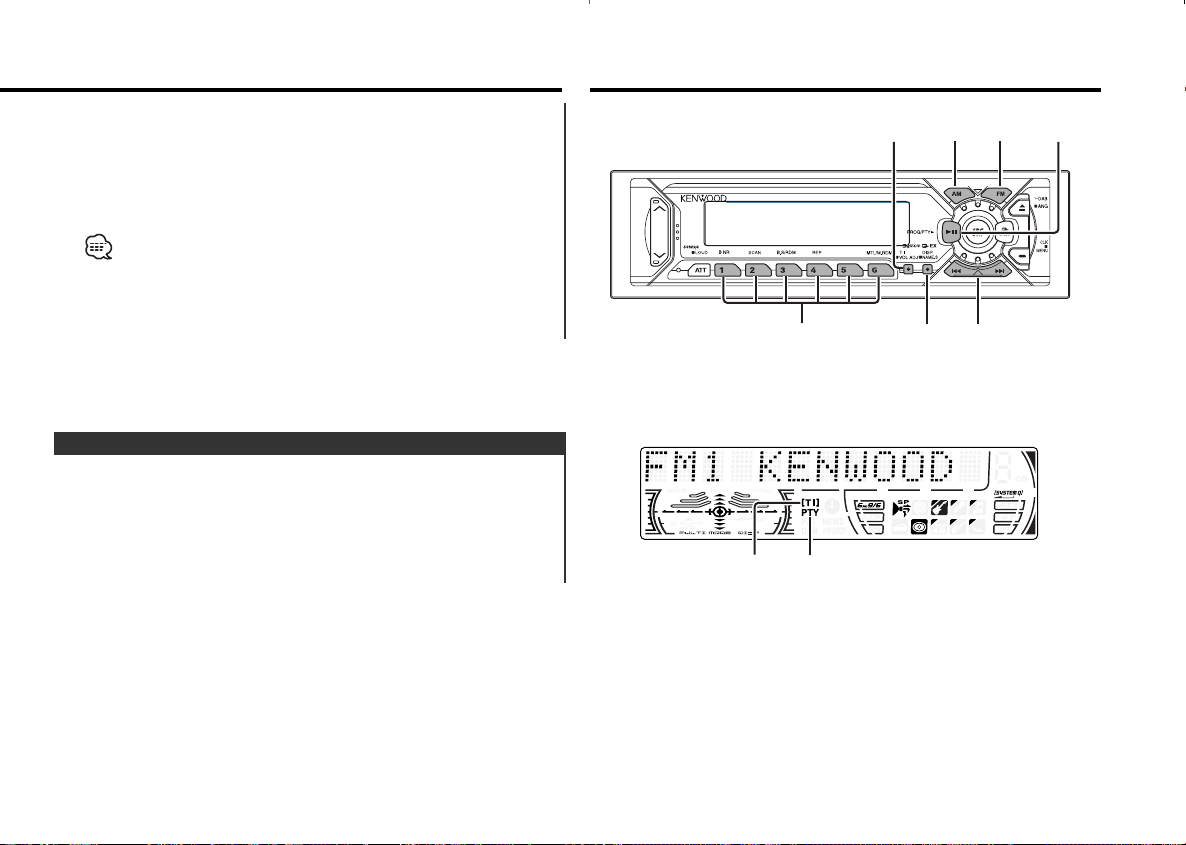
Power
General features
— 6 —
English
u
d
ATT/
LOUD
SRC/
PWR OFF
Q
/AUD
ANG
4/¢
AM
FM
CLK
DISP/
NAME.S
ATT indicator
Speaker Setting indicator
SYSTEM Q indicator
Clock indicator
Page 7
You can recall the best sound setting preset for different types of
the music.
1 Select the source to set
Press the [SRC] button.
2 Select the Sound type
Press the [Q] button.
Each time the button is pressed the sound setting switches.
Sound setting Display
Flat "Flat"
Rock "Rock"
Top 40 "Top 40"
Pops "Pops"
Jazz "Jazz"
Easy "Easy"
Scan of Flat — Easy "Scan"
User memory "User"
• User memory: The values set on the <Audio control> (page 8).
• Each setting value is changed with the <Speaker setting> (page
8).
First, select the speaker type with the Speaker setting.
System Q
Turning the volume down quickly.
Press the [ATT] button.
Each time the button is pressed the Attenuator turns ON or OFF.
When it’s ON, the "ATT" indicator blinks.
Attenuator
Increasing Volume
Press the [u] button.
Decreasing Volume
Press the [d] button.
Volume
The time until full power OFF can be set in <Power OFF Timer>
(page 30).
— 7 —
Compensating for low and high tones during low volume.
Press the [LOUD] button for at least 1 second.
Each time the button is pressed for at least 1 second the
Loudness turns ON or OFF.
When it's ON, "LOUD ON" is displayed.
Loudness
Page 8
Fine-tuning so that the System Q value is optimal when setting
the speaker type.
1 Enter Standby
Press the [SRC] button.
Select the "ALL OFF" display.
2 Enter Speaker Setting mode
Press the [Q] button.
3 Select the Speaker type
Press the [4] or [¢] button.
Each time the button is pressed the setting switches as shown
below.
Speaker type Display
OFF "SP OFF"
For 6 & 6x9 in. speaker "SP 6*9/6inch"
For 5 & 4 in. speaker "SP 5/4inch"
For the OEM speaker "SP O.E.M."
4 Exit Speaker Setting mode
Press the [Q] button.
Speaker Setting
5 Exit Audio Control mode
Press the [AUD] button.
1 Select the source for adjustment
Press the [SRC] button.
2 Enter Audio Control mode
Press the [AUD] button for at least 1 second.
3 Select the Audio item for adjustment
Press the [FM] or [AM] button.
Each time the button is pressed the items that can be adjusted
switch as shown below.
4 Adjust the Audio item
Press the [4] or [¢] button.
Adjustment Item Display Range
Bass Center Frequency "Bass F" 60/70/80/100 or 150 Hz
Bass level "Bass" –8 — +8
Bass Q Factor "Bass Q" 1.00/1.25/1.50/2.00
Bass Extend "Bass EXT" ON/OFF
Middle Center Frequency "MID F" 0.5/1.0/1.5/2.0 kHz
Middle level "Middle" –8 — +8
Middle Q Factor "Middle Q" 1.0/2.0
Treble Center Frequency "TRE F" 10.0/12.5/15.0/17.5 kHz
Treble level "Treble" –8 — +8
Balance "Balance" Left 15 — Right 15
Fader "Fader" Rear 15 — Front 15
Volume offset "V Offset" –8 — ±0
• According to the Bass Q Factor setting value, the frequencies that
can be set in Bass Center Frequency change as shown below.
Bass Q Factor Bass Center Frequency
1.00/1.25/1.50 60/70/80/100
2.00 60/70/80/150
• When the Bass Extend is set to ON, low frequency response is
extended by 20%.
• Volume offset: Each source's volume can be set as a difference
from the basic volume.
Audio Control
General features
— 8 —
English
Page 9
In Tape source
Information
Play side & Tape counter
Play side & Tape running
Play side
In External disc source
Information Display
Track Time
Disc name "DNPS"
Disc title "D-TITLE"
Track title "T-TITLE"
Switching the information displayed.
Press the [DISP] button.
Each time the button is pressed the display switches as shown
below.
In Tuner source
Information Display
Program Service name or Frequency
Radio text "R-TEXT"
Displaying the frequency during Program Service name
reception
Press the [DISP] button for at least 1 second.
The frequency for the RDS station will be displayed for 5
seconds instead of the station name.
Switching Display
— 9 —
Switching the displayed information.
Press the [CLK] button.
Each time the button is pressed it switches between clock
display and current source.
During clock display the clock indicator is ON.
Switching Clock Display
The audio system automatically mutes when a call comes in.
When a call comes in
"CALL" is displayed.
The audio system pauses.
Listening to the audio during a call
Press the [SRC] button.
The "CALL" display disappears and the audio system comes back
ON.
When the call ends
Hang up the phone.
The "CALL" display disappears and the audio system comes back
ON.
TEL Mute
Page 10
The faceplate of the unit can be detached and taken with you,
helping to deter theft.
Removing the Faceplate
1 Turn the ignition OFF or press the [SRC] button for at least 1
second.
The power turns OFF and the faceplate slides open.
2 Holding the center part of the faceplate pull it out.
• When the faceplate is kept remove open, according to the <OFF
Wait Time Setting> (page 27) setting, the faceplate is hidden and
the power turns OFF.
• The faceplate is a precision piece of equipment and can be
damaged by shocks or jolts. For that reason, keep the faceplate in
its special storage case while detached.
• Do not expose the faceplate or its storage case to direct sunlight
or excessive heat or humidity. Also avoid places with too much
dust or the possibility of water splashing.
Reattaching the Faceplate
1 Set the left side of the faceplate in the faceplate bracket.
2 Press the right side of the faceplate until it locks.
Theft Deterrent Faceplate
Press the [ANG] button for at least 1 second.
• Do not apply excessive force to the faceplate. It can cause
damage.
• The faceplate angle cannot be adjusted during tape play.
Faceplate Angle Adjustment
Selecting the display when this device is switched to Auxiliary
input source.
1 Select Auxiliary input source
Press the [SRC] button.
Select the "AUX" display.
2 Enter Auxiliary input display setting mode
Press the [NAME.S] button for at least 2 seconds.
The presently selected AUX Name is displayed.
3 Select the Auxiliary input display
Press the [4] or [¢] button.
Each time the button is pressed it switches through the below
displays.
• "AUX"
• "TV"
• "VCP"
• "GAME"
• "PORTABLE"
4 Exit Auxiliary input display setting mode
Press the [NAME.S] button.
When operation stops for 10 seconds, the name at that time is
selected, and Auxiliary input display setting mode closes.
Auxiliary Input Display Setting
General features
— 10 —
English
Page 11
Tuner features
Prevents tampering with the unit while your car is being serviced
etc.
Hiding the control panel
Press the [SRC] button for at least 1 second.
The faceplate slides open.
When the time set in <OFF Wait Time Setting> (page 27) lapses,
the faceplate is hidden and the power turns OFF.
Showing the control panel
Press the left part at the upper side of the faceplate.
The faceplate will open and show the control panel.
Hiding the Control Panel
— 11 —
SRC
FM
4/¢
AM
# 1-6
MENU
ST indicator
Band display Frequency display
Preset station number
Page 12

Putting a station with good reception in the memory
automatically.
1
Select the band for Auto Memory Entry
Press the [FM] or [AM] button.
2 Enter Menu mode
Press the [MENU] button for at least 1 second.
"MENU" is displayed.
3 Select the Auto Memory Entry mode
Auto Memory Entry
Putting the station in the memory.
1 Select the band
Press the [FM] or [AM] button.
2 Select the frequency to put in the memory
Press the [4] or [¢] button.
3
Put the frequency in the memory
Press the [#1] — [#6] button for at least 2 seconds.
The preset number display blinks 1 time.
On each band, 1 station can be put in the memory on each [#1]
— [#6] button.
Station Preset Memory
Canceling Direct Access Tuning
Press the [DIRECT] button on the remote.
Entering the frequency and tuning.
1
Select the band
Press the [FM] or [AM] button.
2
Enter Direct Access Tuning mode
Press the [DIRECT] button on the remote.
The "– – – –" display.
3 Enter the frequency
Press the number buttons on the remote.
Example:
Desired frequency Press button
92.1 MHz (FM) [#0], [#9], [#2], [#1]
810 kHz (AM) [#0], [#8], [#1], [#0]
Direct Access Tuning (Function of remote)
Selecting the station.
1 Select tuner source
Press the [SRC] button.
Select the "TUNER" display.
2 Select the band
Press the [FM] or [AM] button.
Each time the [FM] button is pressed it switches between the
FM1, FM2, and FM3 bands.
3 Tune up or down band
Press the [4] or [¢] button.
During reception of stereo stations the "ST" indicator is ON.
Tuning
Tuner features
— 12 —
English
Page 13
RDS features
Calling up the stations in the memory.
1 Select the band
Press the [FM] or [AM] button.
2 Call up the station
Press the [#1] — [#6] button.
Preset Tuning
Press the [FM] or [AM] button.
Select the "Auto-Memory" display.
4 Open Auto Memory Entry
Press the [4] or [¢] button for at least 2 seconds.
When 6 stations that can be received are put in the memory
Auto Memory Entry closes.
• When the <AF Function> (page 28) is ON, only RDS stations are
put in the memory.
• When Auto Memory Entry is done in the FM2 band, the RDS
stations preset in the FM1 band aren't put in the memory.
Likewise, when it is done in the FM3 band, RDS stations preset in
FM1 or FM2 aren't put in the memory.
— 13 —
FM PTY
4/¢
AM
DISP# 1-6
TI/
VOL ADJ
TI indicator
PTY indicator
Page 14

Selecting the Program Type and searching for a station.
1 Enter PTY mode
Press the [PTY] button.
During PTY mode the "PTY" indicator is ON.
This function can't be used during a traffic bulletin or AM reception.
2 Select the Program Type
Press the [FM] or [AM] button.
Each time the button is pressed the Program Type switches as
shown below.
No. Program Type Display
1. Speech "Speech"
2. Music "Music"
3. News "News"
4. Current Affairs "Affairs"
5. Information "Info"
6. Sport "Sport"
7. Education "Educate"
8. Drama "Drama"
9. Culture "Culture"
10. Science "Science"
11. Varied "Varied"
12. Pop Music "Pop M"
PTY (Program Type)
Scrolling the displayed radio text.
Press the [DISP] button for at least 1 second.
Radio Text Scroll
Setting the volume during Traffic Information.
1 Receive the station.
2 Set the volume you want.
3 Preset the volume
Press the [VOL ADJ] button for at least 2 seconds.
The volume level display blinks 1 time.
Presetting Volume for Traffic Information
Switching to traffic information automatically when a traffic
bulletin starts even when you aren't listening to the radio.
Press the [TI] button.
Each time the button is pressed the Traffic Information function
turns ON or OFF.
When it's ON, "TI" indicator is ON.
When a traffic information station isn't being received the "TI"
indicator blinks.
When a traffic bulletin starts, "Traffic Info" is displayed it and it
switches to traffic information.
During reception of a AM station when the Traffic Information
function is turned ON, it switches to a FM station.
Receiving other traffic information stations
Press the [4] or [¢] button.
Traffic information station switching can be done when listening to
the radio.
Traffic Information
RDS features
— 14 —
English
Page 15

Putting the Program Type in the Preset button memory and
calling it up quickly.
Presetting the Program Type
1 Select the Program Type to preset
Refer to <PTY(Program Type)> (page 14).
2
Preset the Program Type
Press the [#1] — [#6] button for at least 2 seconds.
Calling up the preset Program Type
1 Enter PTY mode
Refer to <PTY(Program Type)> (page 14).
2 Call up the Program Type
Press the [#1] — [#6] button.
Program Type preset
Press the [PTY] button.13. Rock Music "Rock M"
14. Easy Listening Music "Easy M"
15. Light Classical "Light M"
16. Serious Classical "Classics"
17. Other Music "Other M"
18. Weather "Weather"
19. Finance "Finance"
20. Children's programs "Children"
21. Social Affairs "Social"
22. Religion "Religion"
23. Phone In "Phone In"
24. Travel "Travel"
25. Leisure "Leisure"
26. Jazz Music "Jazz"
27. Country Music "Country"
28. National Music "Nation M"
29. Oldies Music "Oldies"
30. Folk Music "Folk M"
31. Documentary "Document"
• Speech and Music include the Program type shown below.
Speech: No.3
— 11, 18 — 25, 31
Music: No.12
— 17, 26 — 30
• The Program Type can be put in the [#1]
— [#6] button memory
and called up quickly. Refer to the <Program Type preset> (page
15).
• The display language can be changed. Refer to <Changing
Language for PTY Function> (page 16).
3 Search for the selected Program Type station
Press the [4] or [¢] button.
When you want to search for other stations press the [4] or
[¢] button again.
When the selected Program Type isn't found, "NO PTY" is displayed.
Select another Program Type.
4 Exit PTY mode
— 15 —
Page 16

Cassette player features
Selecting the Program Type display language.
1 Enter PTY mode
Refer to <PTY (Program Type)> (page 14).
2 Enter Changing Language mode
Press the [DISP] button.
3 Select the language
Press the [FM] or [AM] button.
Each time the button is pressed the language switches as shown
below.
Language Display
English "English"
Spanish "Spanish"
French "French"
Dutch "Dutch"
Norwegian "Norwegian"
Portuguese "Portuguese"
Swedish "Swedish"
German "German"
4 Exit Changing Language mode
Press the [DISP] button.
Changing Language for PTY Function
RDS features
— 16 —
English
FM
SRC
PROG
4/¢
AM
B NR B.S REP MTL
0
Play side
Tape running display
IN indicator
Page 17

Press the [MTL] button.
Each time the button is pressed the Tape type switches as
shown below.
Tape type Display
CrO2(Type II), FeCr (Type III), Metal (Type IV) "Metal ON"
Normal (Type I) "Metal OFF"
Selecting the Tape type
Press the [B NR] button.
Each time the button is pressed the Dolby B NR turns ON or
OFF.
When it's ON, "B-NR ON" is displayed.
Dolby B NR
Rewinding
Press the [AM] button.
When it's stopped press the [PROG] button.
Fast Forwarding
Press the [FM] button.
When it's stopped press the [PROG] button.
Fast Forwarding and Rewinding
When there's no Cassette Tape inserted
1 Slide open the faceplate
Press the [0] button.
2 Insert a Cassette Tape.
When the faceplate has been slid open, it might interfere with the
shift lever or something else. If this happens, pay attention to safety
and move the shift lever or take an appropriate action, then operate
the unit.
• The sound will be temporarily muted while the faceplate is
moving.
• When there's a Cassette Tape inserted, the "IN" indicator is ON.
When there's a Cassette Tape inserted
Press the [SRC] button.
Select the "TAPE" display.
When you want to listen to the reverse side
Press the [PROG] button.
Eject the Cassette Tape
1 Eject the Cassette Tape
Press the [0] button.
2 Close the faceplate
Press the [0] button.
Playing Cassette Tapes
— 17 —
Page 18

Repeating the present song.
Press the [REP] button.
Each time the button is pressed the Music Repeat turns ON or
OFF.
When it's ON, "Repeat ON" is displayed.
Music Repeat
Fast forwarding automatically when an unrecorded portion
continues for at least 10 seconds.
Press the [B.S] button.
Each time the button is pressed the Blank Skip turns ON or OFF.
When it's ON, "B.Skip ON" is displayed.
Blank Skip
• During the songs first 5 seconds there may be a times when the
previous track is recognized as the current track.
• As many as 9 songs can be skipped.
Designating the song to be skipped with the remote control
number buttons.
1 Designate the song to skip
Press number buttons on the remote.
2 Skipping to a later song
Press the [¢] button.
Skipping to a previous song
Press the [4] button.
Canceling DPSS
Press the [38] button.
DPSS with the Remote
Indicating the songs to skip, and Fast Forwarding or Rewinding.
Skipping to a later song
Press the [¢] button.
Each time the button is pressed the number of songs skipped
increases.
Skipping to a previous song
Press the [4] button.
Each time the button is pressed the number of songs skipped
increases.
Canceling DPSS
Press the [PROG] button.
• During the songs first 5 seconds there may be a times when the
previous song is recognized as the current song.
• As many as 9 songs can be skipped.
DPSS (Direct Program Search System)
Cassette player features
— 18 —
English
Page 19

Fast Forwarding
Hold down on the [¢] button.
Release your finger to play the disc at that point.
Reversing
Hold down on the [4] button.
Release your finger to play the disc at that point.
Fast Forwarding and Reversing
Playing discs set in the optional accessory disc player connected
to this unit.
Press the [SRC] button.
Select the display for the disc player you want.
Display examples:
Display Disc player
"CD" CD player
"DISC" CD changer / MD changer
Pause and play
Press the [38] button.
Each time the button is pressed it pauses and plays.
• Disc #10 is displayed as "0".
• The functions that can be used and the information that can be
displayed will differ depending on the external disc players being
connected.
Playing External Disc
External disc control features
— 19 —
FM SRC38
4/¢
AM
SCAN RDM REP M.RDM DISP/
NAME.S
Track number
Track time
Disc number
Page 20

Playing the first part of each song on the disc you are listening
to and searching for the song you want to listen to.
1 Start Track Scan
Track Scan
Replaying the track/disc you're listening to.
Press the [REP] button.
Each time the button is pressed the Repeat Play switches as
shown below.
Repeat play Display
Track Repeat "T-Repeat ON"/
"Repeat ON"
Album Repeat (Function of disc changer) "D-Repeat ON"
OFF "Repeat OFF"
Track/Album Repeat
Doing Disc Search by entering the disc number.
1 Enter the disc number
Press the number buttons on the remote.
2 Do Album Search
Press the [DISC+] or [DISC–] button.
Canceling Direct Album Search
Press the [38] button.
Input "0" to select disc 10.
Direct Album Search
(Function of disc changers with remote)
Doing Track Search by entering the track number.
1 Enter the track number
Press the number buttons on the remote.
2
Do Track Search
Press the [4] or [¢] button.
Canceling Direct Track Search
Press the [38] button.
Direct Track Search (Function of remote)
Selecting the disc you want to hear.
Press the [AM] or [FM] button.
Album Search (Function of disc changer)
Selecting the song you want to hear.
Press the [4] or [¢] button.
Track Search
External disc control features
— 20 —
English
Page 21

Press the [SCAN] button.
"Scan ON" is displayed.
2 Release it when the song you want to listen to is played
Press the [SCAN] button.
— 21 —
Play the songs on all the discs in the disc changer in random
order.
Press the [M.RDM] button.
Each time the button is pressed the Magazine Random Play turns
ON or OFF.
When it's ON, "M.Random ON" is displayed.
When the [¢] button is pressed, the next song select starts.
Magazine Random Play
(Function of disc changer)
Playing all the songs on the disc in random order.
Press the [RDM] button.
Each time the button is pressed Random Play turns ON or OFF.
When it's ON, "Random ON" is displayed.
When the [¢] button is pressed, the next song select starts.
Random Play
Page 22

Selecting the CD displayed in the DNPS of the CDs set in the
Disc changer.
1 Enter DNPP mode
Press the [DNPP] button on the remote.
When "DNPP" is displayed the DNPS display in order.
Forward / Reverse display
Press the [DISC–] or [DISC+] button.
2 When the disc you want is displayed
Press the [OK] button on the remote.
DNPP (Disc Name Preset Play)
(Function of Remote)
Scrolling the displayed CD text or MD title.
Press the [DISP] button for at least 1 second.
Text/Title Scroll
7 Exit name set mode
Press the [NAME.S] button.
• When operation stops for 10 seconds the name at that time is
registered, and Name Set mode closes.
• Media that you can attach names to
- External CD changer/ player: Varies according to the CD changer/
player. Refer to the CD changer/ player manual.
• The name of a CD can be changed by the same operation you
used to name it.
Attaching a title to a CD.
1 Play the disc you want to attach a name to
• A title can't be attached to a MD.
• Disc Naming can't be done during CD text display.
2 Enter name set mode
Press the [NAME.S] button for at least 2 seconds.
"NAME SET" is displayed.
3 Move the cursor to the enter character position
Press the [4] or [¢] button.
4 Select the character type
Press the [38] button.
Each time the button is pressed the character typed switches as
shown below.
Character type
Alphabet upper case
Alphabet lower case
Numbers and symbols
Special characters (Accent characters)
5 Select the characters
Press the [FM] or [AM] button.
Characters can be entered by using a remote with a number button.
Example: If "DANCE" is entered.
Character Button #Times pressed
"D" [#3] 1
"A" [#2] 1
"N" [#6] 2
"C" [#2] 3
"E" [#3] 2
6 Repeat steps 3 through 5 and enter the name.
Disc Naming (DNPS)
External disc control features
— 22 —
English
Page 23

Menu system
The disc being displayed is played.
Canceling the DNPP mode
Press the [DNPP] button on the remote.
— 23 —
FM
SRC
MENU
4/¢
AM
# 1-6
Menu display
RDS indicator
NEWS indicator
Page 24

Because authorization by the Mask Key is required when it's
removed from the vehicle, personalizing this unit by using the
Mask Key is a help in preventing theft.
1 Enter Standby
Press the [SRC] button.
Select the "ALL OFF" display.
2 Enter Menu mode
Press the [MENU] button for at least 1 second.
When "MENU" is displayed, "Mask key" is displayed.
3 Enter Mask key mode
Press the [4] or [¢] button for at least 1 second.
"TRANSMIT 1" is displayed.
4 Enter the Mask Key's signal
Hold down the transmit button on the Mask Key until the full
transmit level indicator lights up in the display.
"TRANSMIT 2" is displayed.
• Keep the Mask Key close to the signal sensor when you transmit
the Mask Key's signal.
• If the Mask Key's signal does not be received correctly, the display
will return to "TRANSMIT 1". In this case, repeat the procedure in
step 4.
5 Reenter the Mask Key's signal
Hold down the transmit button on the Mask Key until the full
Mask Key
Setting during operation beep sound etc. functions.
The Menu system basic operation method is explained here. The
reference for the Menu items and their setting content is after
this operation explanation.
1 Enter Menu mode
Press the [MENU] button for at least 1 second.
"MENU" is displayed.
2 Select the menu item
Press the [FM] or [AM] button.
Example: When you want to set the beep sound select the
"Beep" display.
3
Set the menu item
Press the [4] or [¢] button.
Example: When "Beep" is selected, each time the button is
pressed it switches "Beep ON" or "Beep OFF". Select 1
of them as the setting.
You can continue by returning to step 2 and setting other items.
4 Exit Menu mode
Press the [MENU] button.
When other items that are applicable to the basic operation method
above are displayed afterwards their setting content chart is
entered. (Normally the uppermost setting in the chart is the original
setting.)
Also, the explanation for items that aren't applicable (<Manual Clock
Adjustment>etc.) are entered step by step.
Menu System
Menu system
— 24 —
English
Page 25

Selecting the button illumination color as green or red.
Display Setting
"Button Green" The illumination color is green.
"Button Red" The illumination color is red.
Selectable Illumination
Synchronizing the RDS station time data and this unit's clock.
Display Setting
"SYNC ON" Synchronizes the time.
"SYNC OFF" Adjust the time manually.
It takes 3 to 4 minutes to synchronize the clock.
Synchronize Clock
2 Enter Clock Adjust mode
Press the [4] or [¢] button for at least 1 second.
The clock display blinks.
3 Adjust the hours
Press the [FM] or [AM] button.
Adjust the minutes
Press the [4] or [¢] button.
4 Exit Clock adjustment mode
Press the [MENU] button.
This adjustment can be done when the <Synchronize Clock> (page
25) is set as OFF.
1 Select Clock Adjustment mode
Press the [FM] or [AM] button.
Select the "Clock Adjust" display.
Manual Clock Adjustment
Setting the operation check sound (beep sound) ON/OFF.
Display Setting
"Beep ON" Beep is heard.
"Beep OFF" Beep canceled.
Touch Sensor Tone
transmit level indicator lights up in the display.
"APPROVED" is displayed, and the Mask Key function activates.
Press the Reset button and when it's removed from the
battery power source
1 Turn the power ON
The vehicle engine turns ON.
"TRANSMIT 1" is displayed.
2 Enter the Mask Key's signal
Repeat steps 4 and 5 abobe, and enter the Mask Key's signal.
"APPROVED" is displayed.
The unit can be used.
— 25 —
Page 26

Adjusting the display contrast.
Display and Setting
"Contrast 0"
"Contrast 5" (Original setting)
"Contrast 10"
… …
Contrast Adjustment
Display Color mode
"Scan" The color changes in sequence.
"SRC" The color changes according to the selected source.
"Time" The color changes every six hours.
Keeps the presently set color.
Blue fine adjustment
1 Press the [#3] button for at least 2 seconds.
2 Press the [4] or [¢] button.
When the blue fine adjustment is completed, press the [#3]
button.
The set color memory
Press the [#5] button for at least 2 seconds.
When the setting in the memory is called up press the [#5]
button.
The blue fine adjustment setting cannot be stored in memory.
Function of the KRC-V791
You can set the display to a desired color.
1 Select Illumination Color Setting Mode
Press the [FM] or [AM] button.
Select the "COL" display.
2 The color continues to change gradually
Continue pressing the [4] or [¢] button.
Release your finger at the color you want.
Quick call up the preset color
Press the [#1] — [#4] button.
Button Color
[#1] Silky White
[#2] Red
[#3] Blue
[#4] Blue Green
Selecting the Color mode
Press the [#6] button.
Each time the button is pressed the Color mode switches as
shown below.
Illumination Color Setting
Setting the graphic part display ON/OFF.
Display Setting
"Graphic ON" The graphic part is displayed.
"Graphic OFF" The graphic part isn't displayed.
Switching Graphic Display
Menu system
— 26 —
English
Page 27

Adjust the bass boost level of the external amplifier using the
main unit.
Display Setting
"AMP Bass FLT" Bass boost level is flat.
"AMP Bass +6" Bass boost level is low (+6dB).
"AMP Bass +12" Bass boost level is high (+12dB).
Refer to the catalog or instruction manual for power amplifiers that
can be controlled from this unit.
B.M.S. (Bass Management System)
Display Setting
"System Q ON" The System Q factors are displayed.
"System Q OFF" The System Q factors aren't displayed.
Setting display/don't display for the System Q factors (Bass
center frequency, Bass Q factor, Bass extend, Middle center
frequency, Middle Q factor, and Treble center frequency) in
Audio control.
System Q
Setting the time until the faceplate hide operation starts after the
power is turned OFF.
The faceplate can be removed only during the set time period.
Display and Setting
"Off Wait 0s"
"Off Wait 3s" (Original setting)
"Off Wait 25s"
… …
OFF Wait Time Setting
Dimming this unit's display automatically when the vehicle light
switch is turned ON.
Display Setting
"Dimmer ON" The display dims.
"Dimmer OFF" The display doesn't dim.
Dimmer
— 27 —
Page 28

When poor reception is experienced, automatically switch to
another frequency broadcasting the same program in the same
RDS network with better reception.
Display Setting
"AF ON" The AF function is ON.
"AF OFF" The AF function is OFF.
AF (Alternative Frequency)
For the operation method refer to <Auto Memory Entry>
(12page).
Auto Memory Entry <In Tuner mode>
Sets the tuning mode.
Tuning mode Display Operation
Auto seek "Auto1" Automatic search for a station.
Preset station seek "Auto2" Search in order of the stations in
the Preset memory.
Manual "Manual" Normal manual tuning control.
Tuning Mode <In Tuner mode>
"Local.S ON" The local seek function is ON.
Only stations whose reception is good are searched for in auto
seek tuning.
Display Setting
"Local.S OFF" The local seek function is OFF.
Local Seek <In Tuner mode>
It switches automatically when a news bulletin starts even if the
radio isn't being listened to. Also, the time interval when
interrupt is prohibited can be set.
Display and Setting
"News OFF"
"News 00min"
"News 90min"
When "News 00min" — "News 90min" is set, the News Bulletin
Interrupt function is ON.
When it's ON, the "NEWS" indicator is ON.
When the news bulletin starts, "News " is displayed, and it
switches to the news bulletin.
• If you choose the "20min" setting, further news bulletins will not
be received for 20 minutes once the first news bulletin is received.
• The news bulletin volume is the same level that was set for traffic
information (page 14).
• This function is only available if the desired station sends PTY-code
for news bulletin or belongs to <Enhanced Other Network>Network sending PTY-code for news bulletin.
• When the News Bulletin Interrupt function is ON, it switches to an
FM station.
…
News Bulletin with Timeout Setting
Menu system
— 28 —
English
Page 29

Setting the displayed text scroll.
Display Setting
"Scroll MANU" Doesn't scroll.
"Scroll Auto" Scrolls when the display changes.
The text scrolled is shown below.
• CD text
• MD title
• Radio text
Text Scroll
Noise can be reduced when stereo broadcasts are received as
monaural.
Display Setting
"MONO OFF" The monaural reception is OFF.
"MONO ON" The monaural reception is ON.
Monaural Reception <In FM reception>
Display Setting
"ATPS ON" The Auto TP Seek Function is ON.
"ATPS OFF" The Auto TP Seek Function is OFF.
When the TI function is ON and poor reception conditions are
experienced when listening to a traffic information station,
another traffic information station with better reception will be
searched for automatically.
Auto TP Seek
You can choose whether or not to restrict the RDS channels,
received with the AF function for a particular network, to a
specific region.
Display Setting
"Regional ON" The Region Restrict Function is ON.
"Regional OFF" The Region Restrict Function is OFF.
Sometimes stations in the same network broadcast different
programs or use different program service names.
Restricting RDS Region
(Region Restrict Function)
When the AF function is ON, the "RDS" indicator is ON.
When no other stations with stronger reception are available for the
same program in the RDS network, you may hear the incoming
broadcast in bits and snatches. Turn OFF the AF function in such a
case.
— 29 —
Page 30

Basic Operations of remote
Setting the timer to turn this unit's power OFF automatically
when Standby mode continues.
Using this setting can save the vehicle's battery power.
Display Setting
"OFF – – – –" Power OFF Timer function is OFF.
"OFF 20min" Turns the power OFF after 20 minutes.
(Original setting)
"OFF 40min" Turns the power OFF after 40 minutes.
"OFF 60min" Turns the power OFF after 60 minutes.
Power OFF Timer
Menu system
— 30 —
English
[#0] — [#9]
FM/AM/DISC
+
/DISC–
ATT
38
4/¢
VOL.
SRC
DIRECT/OK
DNPP
Page 31

[FM]/ [AM] buttons
Select the band.
Each time the [FM] button is pressed it switches between the
FM1, FM2, and FM3 bands.
[4]/ [¢] buttons
Tune up or down band.
[#0] — [#9] buttons
Press buttons [#1] — [#6] to recall preset stations.
[DIRECT] button
Enters and cancels the <Direct Access Tuning> (page 12) mode.
[38] button
Enters and cancels the <PTY (Program Type)> (page 14) mode.
In Tuner source
[VOL.] buttons
Adjusting the volume.
[SRC] button
Each time the button is pressed the source switches.
For the source switching order refer to <Selecting the Source>
(page 6).
[ATT] button
Turning the volume down quickly.
When it is pressed again it returns to the previous level.
Basic operations
Use one lithium battery (CR2025).
Insert the batteries with the + and – poles aligned properly,
following the illustration inside the case.
Store unused batteries out of the reach of children. Contact a doctor
immediately if the battery is accidentally swallowed.
Do not set the remote on hot places such as above the dashboard.
2WARNING
Loading and Replacing the battery
— 31 —
Page 32

[#0] — [#9] buttons
When in <Direct Track Search> (page 20) and <Direct Album
Search> (page 20), enter the track/disc number.
[4]/ [¢] buttons
Doing track forward and backward.
[DISC+]/ [DISC–] buttons
Doing album forward and backward.
[38] button
Each time the button is pressed the song pauses and plays.
[DNPP]/ [OK] button
Enters and cancels the <DNPP (Disc Name Preset Play)> (page
22) mode.
In Disc source
[4]/ [¢] buttons
Do <DPSS (Direct Program Search System)> (page 18).
[38] button
Plays the reverse side of the tape.
[FM ] button
Fast forwards the tape.
When the [38] button is pressed it releases.
[AM] button
Rewinds the tape.
When the [38] button is pressed it can be released.
[#0] — [#9] buttons
When in <DPSS with the Remote> (page 18) enter the number
of songs.
In Cassette tape source
Basic Operations of remote
— 32 —
English
Page 33

— 33 —
The use of any accessories except for those provided might result in
damage to the unit. Make sure only to use the accessories shipped with
the unit, as shown above.
.........1
1
.........1
3
.........1
4
1. To prevent short circuits, remove the key from the ignition and
disconnect the - terminal of the battery.
2. Make the proper input and output wire connections for each unit.
3. Connect the wire on the wiring harness.
4. Take Connector B on the wiring harness and connect it to the
speaker connector in your vehicle.
5. Take Connector A on the wiring harness and connect it to the
external power connector on your vehicle.
6. Connect the wiring harness connector to the unit.
7. Install the unit in your car.
8. Reconnect the - terminal of the battery.
9. Press the left part at the upper side of the faceplate once to
make the faceplate control panel appear.
• If your car is not prepared for this special connection-system,
consult your KENWOOD dealer.
• Only use antenna conversion adapters (ISO-JASO) when the
antenna cord has an ISO plug.
• Make sure that all wire connections are securely made by
inserting jacks until they lock completely.
• If your vehicle's ignition does not have an ACC position, or if the
ignition wire is connected to a power source with constant
voltage such as a battery wire, the power will not be linked with
the ignition (i.e., it will not turn on and off along with the
ignition). If you want to link the unit's power with the ignition,
connect the ignition wire to a power source that can be turned
on and off with the ignition key.
• If the fuse blows, first make sure that the wires have not caused
a short circuit, then replace the old fuse with one with the same
rating.
• Insulate unconnected wires with vinyl tape or other similar
material. To prevent short circuits, also do not remove the caps
on the ends of the unconnected wires or the terminals.
• Connect the speaker wires correctly to the terminals to which
they correspond. The unit may receive damage or fail to work if
you share the - wires and/or ground them to any metal part in
the car.
• After the unit is installed, check whether the brake lamps,
indicators, wipers, etc. on the car are working properly.
• If the console has a lid, make sure to install the unit so that the
faceplate does not hit the lid when closing and opening.
2CAUTION
.........1
5
.........2
2
External view
......... Number of items
External view
......... Number of items
Accessories
Installation Procedure
Page 34

English
— 34 —
Front left output (White) 14
Front right output (Red) 13
Rear right output (Red) 11
Rear left output (White) 12
Connector Function Guide
Pin Numbers for
ISO Connectors
Wire Color Functions
External Power
Connector
A–4
A–5
A–6
A–7
A–8
Speaker
Connector
B–1
B–2
B–3
B–4
B–5
B–6
B–7
B–8
Yellow
Blue/White
Orange/White
Red
Black
Purple
Purple/Black
Gray
Gray/Black
White
White/Black
Green
Green/Black
Battery
Power Control
Dimmer
Ignition (ACC)
Earth (Ground)
Connection
Rear Right (+)
Rear Right (–)
Front Right (
+)
Front Right (
–)
Front Left (+)
Front Left (
–)
Rear Left (
+)
Rear Left (–)
Battery wire (Yellow) 6
Ignition wire (Red) 7
FM/AM
antenna input
2
Antenna Cord (ISO) 3
Antenna Conversion Adaptor (ISO–JASO) (Accessory3) 1
Wiring harness
(Accessory1)
5
Connect to the terminal that is
grounded when either the telephone
rings or during conversation. 24
Power control/ Motor antenna
control wire (Blue/White) 22
Connect either to the power control
terminal when using the optional
power amplifier, or to the antenna
control terminal in the vehicle. 26
A–7 Pin (Red) 8
A–4 Pin (Yellow) 9
Connector B
Fuse(10A)
4
Connector A
TEL mute wire (Brown) 21
To connect the KENWOOD
navigation system, consult your
navigation manual. 25
External amplifier
control wire
(Pink / Black)20
To "EXT.AMP.CONT." terminal of the
amplifier having the external amp
control function. 23
To KENWOOD disc changer/
DAB control input/
KPA-SD100/KPA-HD100/KPA-SS100 16
To connect these leads, refer
to the relevant instruction
manuals. 17
Connecting Wires to Terminals
TEL MUTE
EXT.CONT.
P.CONT.OUT
ANT.CONT
1234567
8
1234567
8
REAR FRONT
R
L
If no connections
are made, do not
let the wire come
out from the tab. 27
Page 35

— 35 —
Make sure that the unit is installed securely in place. If the unit is
unstable, it may malfunction (eg, the sound may skip).
Bend the tabs of the
mounting sleeve
with a screwdriver or
similar utensil and
attach it in place.
Metal mounting
strap
(commercially
available)
Self-tapping
screw
(commercially
available)
Firewall or metal support
Screw (M4X8)
(commercially
available)
To attach this unit, make sure the front of the control panel faces you
and fit it into the mounting sleeve by pressing the four corners of the
hard rubber frame at the same time.
Do not apply strong pressure to other sections than the corners;
otherwise troubles such as the impossibility of opening or closing the
panel may result.
Installtion
Connecting the ISO Connector (see p.34)
The pin arrangement for the ISO connectors depends on the type
of vehicle you drive. Make sure to make the proper connections to
prevent damage to the unit.
The default connection for the wiring harness is described in 1
below. If the ISO connector pins are set as described in 2 or 3,
make the connection as illustrated.
2WARNING
Unit Vehicle
Ignition wire (Red)
Battery wire (Yellow)
A–7 Pin (Red)
A–4 Pin (Yellow)
Unit Vehicle
Ignition wire (Red)
Battery wire (Yellow)
A–7 Pin (Red)
A–7 Pin (Red)
A–4 Pin (Yellow)
1 (Default setting) The A-7 pin (red) of the vehicle's ISO
connector is linked with the ignition, and the A-4 pin (yellow)
is connected to the constant power supply.
2 The A-7 pin (red) of the vehicle's ISO connector is connected
to the constant power supply, and the A-4 pin (yellow) is
linked to the ignition.
Unit Vehicle
Ignition wire (Red)
Battery wire (Yellow)
3 The A-4 pin (yellow) of the vehicle's ISO connector is not
connected to anything, whilst the A-7 pin (red) is connected to
the constant power supply (or both the A-7 (red) and A-4
(yellow) pins are connected to the constant power supply).
Connect to a power source
that can be turned on and
off with the ignition key.
Page 36

English
— 36 —
1 Insert the removal tool into the
indentations in the hard rubber
frame, and pull it gently until the
lock is released.
Accessory4
Removal tool
Screw (M4X8)
(commercially available)
4 Push upward the removal tool
toward the top, and pull out the
unit halfway while pressing
towards the inside.
5 Pull the unit all the way out
with your hands, being
careful not to drop it.
Be careful to avoid injury from the catch
pins on the removal tool.
2 Remove the screw (M4×8)
on the back panel.
3 Insert the two removal tools
deeply into the slots on each
side, as shown.
Accessory2
Removal tool
Removing the Unit
3 Refer to the section "Removing the faceplate" (page 10) and
then reattaching the faceplate.
Never insert the taptite screws (ø2 X 4 mm) in any other screw holes
than the one specified. If you insert it in another hole, it will contract and
may cause damage to the mechanical parts inside the unit.
If you want to lock the faceplate to the unit so that it does not fall
off, follow the directions below.
1 Refer to the function "Removing the faceplate" (page 10) and
remove the faceplate.
2 Insert the provided screw into the hole at the center of the
bottom side of the faceplate which you have removed from the
unit.
Accessory5
Locking the faceplate to the unit
Page 37

— 37 —— 37 —
What might seem to be a malfunction in your unit may
just be the result of slight misoperation or miswiring.
Before calling service, first check the following table
for possible problems.
General
? The power does not turn ON.01
✔ The fuse has blown.
☞ After checking for short circuits in the wires, replace the fuse with
one with the same rating.
✔ No ACC position on vehicle ignition.02
☞ Connect the same wire to the ignition as the battery wire.
? If you have selected Standby mode, the power will go OFF
automatically.03
✔ The Power OFF Timer function has been activated.
☞ If you do not want the power to go OFF automatically, cancel the
Power OFF Timer function.
?
Nothing happens when the buttons are pressed.04
✔ The computer chip in the unit is not functioning normally.
☞ Press the reset button on the unit (page 4).
? There’s a source you can’t switch.05
✔ There’s no tape inserted.
☞ Set the media you want to listen to. If there’s no media in this
unit, you can't swhich to each source.
✔ The Disc changer isn’t connected.08
☞ Connect the Disc changer. If the Disc changer isn’t connected to
it's input terminal, You can't switch to an external disc source.
? The faceplate does not open or close.09
✔ The faceplate is incorrectly attached.
☞ Reattach the faceplate correctly, See the section on <Removing
the Faceplate>(page 10).
? The memory is erased when the ignition is turned OFF.10
✔ The battery wire has not been connected to the proper terminal.
☞ Connect the wire correctly, referring to the section on
<Connecting Wires to Terminals>.
✔ The ignition and battery wire are incorrectly connected.11
☞ Connect the wire correctly, referring to the section on
<Connecting Wires to Terminals>.
? The TEL mute function does not work.15
✔ The TEL mute wire is not connected properly.
☞ Connect the wire correctly, referring to the section on
<Connecting Wires to Terminals>.
? The TEL mute function turns ON even though the TEL mute wire is
not connected.16
✔ The TEL mute wire is touching a metal part of the car.
☞ Pull the TEL mute wire away from the metal part of the car.
? Even if Loudness is turned ON, high-pitched tone isn't compensated
for. 17
✔ Tuner source is selected.
☞ High-pitched tone isn't compensated for when in Tuner source.
? The Bass center frequency, Bass quality factor, Bass extend, Middle
center frequency, Middle quality factor, and Treble center frequency
can’t be adjusted.19
✔ The <System Q> (page 27) is set OFF.
☞ Set it ON.
? No sound can be heard, or the volume is low.
✔ The fader or balance settings are set all the way to one side.21
☞ Center the fader and balance settings.
✔ The input/output wires or wiring harness are connected incorrectly.22
☞ Reconnect the input/output wires or the wiring harness correctly.
See the section on <Connecting Wires to Terminals>.
✔ The cassette tape is bad.23
☞ Try playing another cassette tape. If works fine, the first tape was
bad.
✔ The values of Volume offset are low.24
☞ Increase the values of Volume offset. (page 8)
?
The sound quality is poor or distorted.25
✔ One of the speaker wires is being pinched by a screw in the car.
☞ Check the speaker wiring.
✔ The tape head is dirty.26
☞ Clean the tape head.
✔ The speakers are not wired correctly.27
☞ Reconnect the speaker wires so that each output terminal is
connected to a different speaker.
Troubleshooting Guide
Page 38

English
— 38 —— 38 —
? The Mask Key item isn’t displayed in the Menu System.33
✔ The Mask Key function is already activated.
☞ When the Mask Key function is activated it isn’t displayed in the
menu items.
? The Touch Sensor Tone doesn’t sound.34
✔ The preout jack is being used.
☞ The Touch Sensor Tone can’t be output from the preout jack.
? Even though Synchronize Clock is ON, the clock can’t be adjusted.35
✔ The received RDS station isn’t sending time data.
☞ Receive another RDS station.
? Even though the vehicle light switch is turned ON, the unit’s display
won’t dim.36
✔ The dimmer wire isn’t connected.
☞ Connect the dimmer wire correctly.
? The Dimmer function doesn’t work. 38-1
✔ The Dimmer wire isn’t connected correctly.
☞ Check the Dimmer wire connection.
? The display color changes subtly. 38-2
✔ This is because thetemperature is different than the temperature
when the setting was done.
☞ The display color condition changes subtly according.to the
ambient temperature.
Tuner source
? Radio reception is poor.39
✔ The car antenna is not extended.
☞ Pull the antenna out all the way.
✔ The antenna control wire is not connected.40
☞ Connect the wire correctly, referring to the section on
<Connecting Wires to Terminals>.
? The desired frequency can’t be entered with the Direct Access
Tuning.41
✔ A station that can’t be received is being entered.
☞ Enter a station that can be received.
✔ You ’re trying to enter a frequency with a 0.01 MHz unit.42
☞ What can be designated in the FM band is to 0.1 MHz.
? It isn't the set Traffic information sound volume. 43
✔ The set sound volume is less than the tuner sound volume.
☞ If the tuner sound volume is louder than the set sound volume,the
tuner sound volume is used.
Cassette tape source
? Can’t remove tape.44
✔ The cause is that more than 10 minutes has elapsed since the vehicle
ACC switch was turned OFF.
☞ The tape can only be removed within 10 minutes of the ACC
switch being turned OFF. If more than 10 minutes has elapsed,
turn the ACC switch ON again and press the Eject button.
? The DPSS, Tape Advance and Music Repeat don’t operate
correctly.45
✔ The space between the songs on the tape can’t be recognized
because it’s too short.
☞ Have at least 4 seconds between songs.
✔ The space between songs can’t be recognized because there’s too
much noise between songs.46
☞ Reduce the noise between songs.
?
The blank skip doesn’t work.47
✔ Because noise is too loud, the non-recorded part can’t be recognized.
☞ Reduce the noise between songs.
? Blank Skip functions at places that are recorded.48
✔ Because the recording level is low, it’s recognized as not recorded.
☞ Turn Blank Skip OFF.
Disc source
? "AUX" is displayed without achieving External disc control mode.50
✔ O-N switch is set to "O" side.
☞ Set the switch to "N" side.
✔ Unsupported disc changer is connected.51
☞ Connect the supported disc changer. (page 3)
? The specified disc does not play, but another one plays instead.52
✔ The specified CD is quite dirty.
☞ Clean the CD.
✔ The CD is upside-down.53
☞ Load the CD with the labeled side up.
✔ The disc is loaded in a different slot from that specified.54
Troubleshooting Guide
Page 39

— 39 —— 39 —
☞ Eject the disc magazine and check the number for the specified
disc.
✔ The disc is severely scratched.55
☞ Try another disc instead.
? The specified track will not play.58
✔ Random play or magazine random play has been selected.
☞ Turn off random play or magazine random play.
? Track repeat, disc repeat, track scan, random play, and magazine
random play start by themselves.59
✔ The setting is not canceled.
☞ The settings for these functions remain on until the setting to off
or the disc ejected, even if the power is turned off or the source
changed.
? Cannot play CD-R or CD-RW.60
✔ Finalization processing is not being conducted for CD-R/CD-RW.
☞ Conduct finalization processing with CD recorder.
✔ A non-compatible CD changer is being used to play the CD-R/CD-
RW.61
☞ Use a CD changer compatible with CD-R/CD-RW to play.
? Direct Track Search and Direct Disc Search can’t be done.66-1
✔ Another function is ON.
☞ Turn Random Play or other functions OFF.
? Track Search can't be done.66-2
✔ For the albums first or last song.
☞ For each album, Track Search can't be done in the backward
direction for the first song or in the forward direction for the last
song.
If the following situations, consult your nearest service
center:
• Even though the disc changer is connected, the Disc Changer source is
not ON, with "AUX" showing in the display during the Changer Mode.
• Even though no device (KCA-S210A, CA-C1AX, KDC-CPS87, KDC-CX87,
KDC-CPS85, KDC-CX85, KDC-CPS82 or KDC-CX82) is connected, the
Auxiliary input is entered when switching modes.
Page 40

English
— 40 —— 40 —
The messages shown below display your systems
condition.
Eject: No disc magazine has been loaded in the changer.
The disc magazine is not completely loaded.E01
➪
Load the disc magazine properly.
No CD in the unit.
➪ Insert the CD.
No Disc: No disc has been loaded in the disc magazine.
E02
➪
Load a disc into the disc magazine.
TOC Error: No disc has been loaded in the disc magazine.
E04
➪
Load a disc into the disc magazine.
The CD is quite dirty. The CD is upside-down. The CD
is scratched a lot.
➪ Clean the CD and load it correctly.
Blank DISC: Nothing has been recorded on the MD.
E10
No Tr DISC: No tracks are recorded on the MD, although it has a
title.E11
NO PANEL: The faceplate of the slave unit being connected to
this unit has been removed.E30
➪
Replace it.
E-77: The unit is malfunctioning for some reason.
E77
➪
Press the reset button on the unit. If the "E-77"
code does not disappear, consult your nearest
service center.
Mecha Error: Something is wrong with the disc magazine. Or the
unit is malfunctioning for some reason.
E99
➪
Check the disc magazine. And then press the reset
button on the unit. If the "Mecha Error" code does
not disappear, consult your nearest service center.
Hold Error: The protective circuit in the unit activates when the
temperature inside the automatic disc changer
exceeds 60°C (140°F), stopping all operation.
E0d
➪
Cool down the unit by opening the windows or
turning on the air conditioner. As the temperature
falls below 60°C (140°F), the disc will start playing
again.
NO NAME: Attempted to display DNPS during the CD play having
no disc names preset.
E51
NO TITLE: Attempted to display the disc title or track title while
the MD having no MD title is being played.E53
NO TEXT: • Attempted to display the disc text or track text
while the CD having no CD text is being played.E54
• Attempted to display text during reception of the
station that isn't sending text data.E55
Waiting: Radio text data is being received.E56
Load: Discs are being exchanged in the Disc changer.E57
NO ACCESS: After setting it in the Disc Changer, DNPP was done
without having it been played at least 1 time.E58
IN (Blink): The tape player section is not operating properly.E60
➪
Reinsert the Tape. If the tape cannot be ejected or
the display continues to flash even when the tape
has been properly reinserted, please switch off the
power and consult your nearest service center.
NOT.AVAILABLE Adjust the panel angle during tape play.
E62
Troubleshooting Guide
Page 41

— 41 —— 41 —
Specifications
FM tuner section
Frequency range (50 kHz space) ..............87.5 MHz – 108.0 MHz
Usable sensitivity (S/N = 26dB) .................................0.7 µV/75 Ω
Quieting Sensitivity (S/N = 46dB) ..............................1.6 µV/75 Ω
Frequency response (±3 dB).................................30 Hz – 15 kHz
Signal to Noise ratio (MONO)..............................................65 dB
Selectivity (DIN) (±400 kHz)............................................. ≥ 80 dB
Stereo separation (1 kHz) ....................................................35 dB
MW tuner section
Frequency range (9 kHz Space).....................531 kHz – 1611 kHz
Usable sensitivity (S/N = 20dB) ...........................................25 µV
LW tuner section
Frequency range .............................................153 kHz – 281 kHz
Usable sensitivity (S/N = 20dB) ...........................................45 µV
Cassette player section
Tape Speed...............................................................4.76 cm/sec.
Wow & Flutter (WRMS) ....................................................0.08 %
Frequency response (±3 dB) (70 µs)......................30 Hz – 20 kHz
Separation (1 kHz) ...............................................................43 dB
Signal to Noise ratio
Dolby NR OFF............................................................57 dB
Dolby B NR ON..........................................................65 dB
Audio section
Maximum output power.................................................50 W × 4
Output power (DIN 45324, +B=14.4V)...........................30 W × 4
Tone action
Bass : ..........................................................100 Hz ±10 dB
Middle : .........................................................1 kHz ±10 dB
Treble :.........................................................10 kHz ±10 dB
Preout level / Load (during disc play) .................1800 mV / 10 kΩ
Preout impedance............................................................≤ 600 Ω
General
Operating voltage (11 – 16V allowable) ..............................14.4 V
Current consumption.............................................................10 A
Installation Size (W x H x D) .........................182 x 53 x 155 mm
Weight ................................................................................1.4 kg
Specifications subject to change without notice.
Page 42

 Loading...