

Kenwood KDC-W6027Y, KDC-W6027, KDC-MP6026 Service Manual
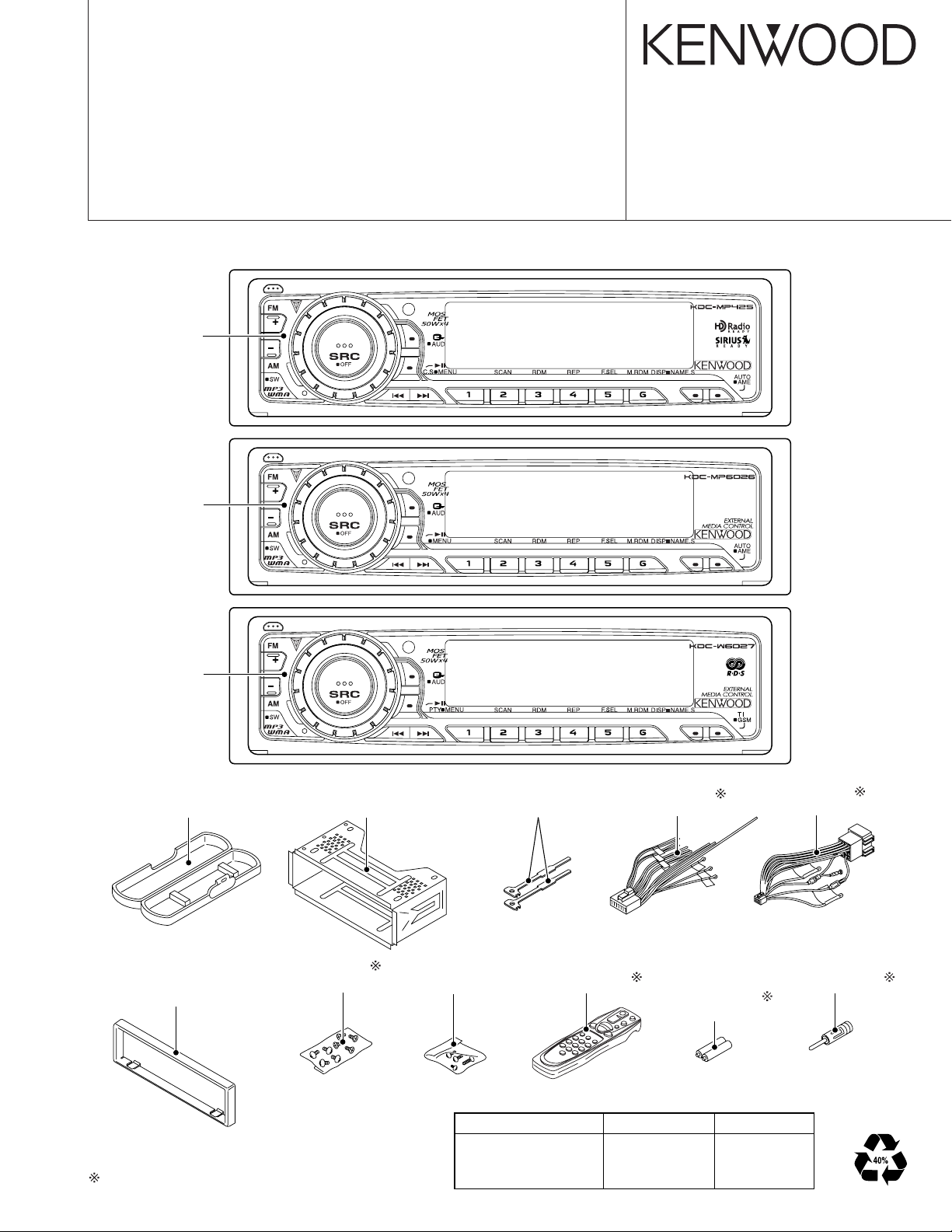
CD RECEIVER
KDC-MP 425/MP6026
/W6027/W6027Y
SERVICE MANUAL
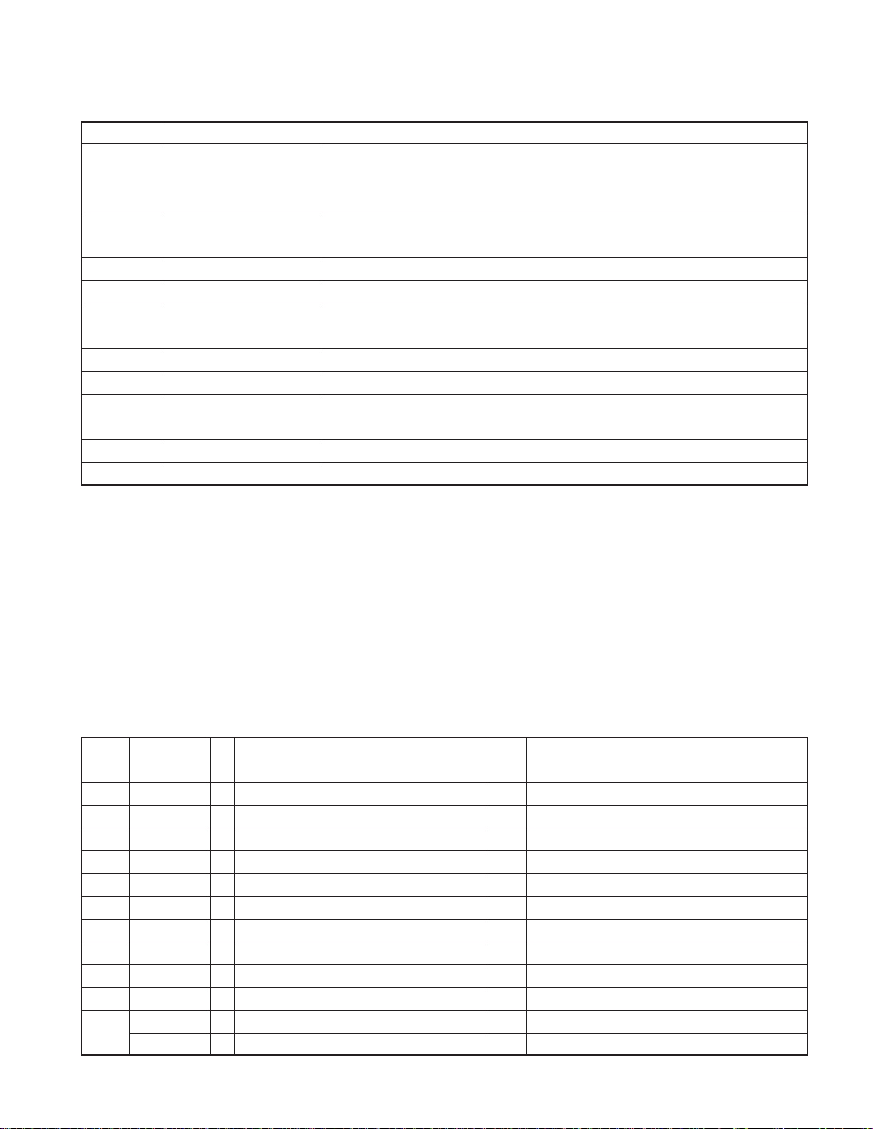
CD MECHANISM EXTENSION CORD (24P) : W05-0934-00
KDC-MP425
Panel assy
(A64-3187-12)
KDC-MP6026
© 2003-12 PRINTED IN JAPAN
B53-0116-00 (N) 2704
Panel assy
(A64-3194-12)
KDC-W6027
/W6027Y
Panel assy
(A64-3197-12)
Plastic cabinet assy
(A02-1486-13)
Mounting hardware assy
(J22-0011-03)
Lever
(D10-4589-04)
x2
DC cord
(E30-6295-05)
DC cord
(E30-4958-05)
Escutcheon
(B07-3098-02):KDC-MP425
(B07-3083-02):Others
Depends on the model. Refer to the parts list.
Screw set
(N99-1719-05)
Screw set
(N99-1730-15)
TDF PANEL INFORMATION
MODEL TDF PANEL No. TDF NAME
KDC-MP425 Y33-1920-61 TDF-44D
KDC-MP6026 Y33-1920-64 TDF-MP6026
KDC-W6027/W6027Y Y33-1920-65 TDF-W6027
Remote controller assy (RC-505)
(A70-2040-05)
Size AA battery
(Not suplied)
Antenna adaptor
(T90-0523-05)
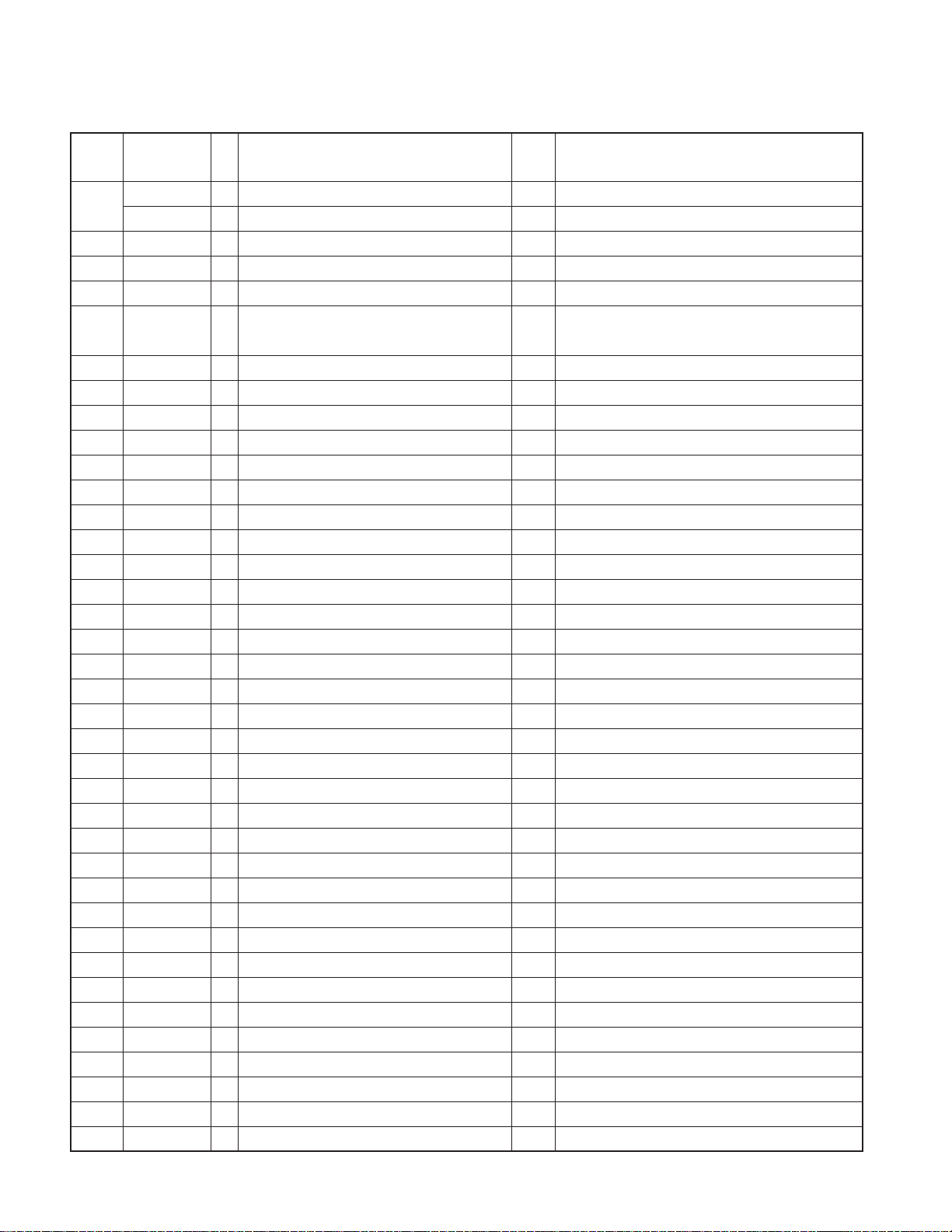
KDC-MP 425/MP6026
BUFFER
Q101
RDS
DECODER
IC7
Q201
BUFFER
IC1
(V-ILL ONLY)
DA CONVERTER
IC2
REMOCON
RESET SW
ENCODER
ROTARY
S1
WITH
LCD DRIVER
KEY MATRIX
IC1
LCD
PANEL DET
EJECT SW
S1
EJECT ILLUMI
DSI
SYSTEM
MICROPROCESSOR
IC2
MPX
E-VOL
&
EXT AMP
DIMMER
ACC DET
TEL MUTE
B.U DET
PRE MUTE
PRE MUTE
PRE MUTE
DRIVER
MUTE
IC6
POWER
IC
IC4
THERMAL
PROTECT
PRE OUT
(REAR/NF)
EXT.AMP.CON
DIMMER
ACC
TEL MUTE
BACK UP
AUX IN
(REAR) 3PRE
PRE OUT
(FRONT)
PRE OUT
SP OUT
SURGE DET
SW REG
CD MECHA+B
SERVOSERVO+B
SW 14V
Q21
IC9
OPEL DISP I/F
WIRED REMO/
SUPPLY
IC
IC3
POWER
ANT CON
P CON
RESET
IC8
SW 5V
Q4
PANEL 5V
Q152
SW5V
S-METER
AUDIO OUT
IFC OUT
PLL-DATA
PLL-CLK
SW5V
AM+B
A8V
SW3
SW2
SW1
MS CLK
MS DATA
M MUTE L
SW4
M MUTE R
LO/EJ
M STOP
MOSW
M RST
SERVO+B
A8V
BU5V
CD MECHA+B
DATA C
CH MUTE
CH RST
REQ H
REQ C
CH CLK
CH-CON
DATA H
BACK UP
NOISE
QUAL
S-METER
R DATA
R CLK
FM
AM
MP IN
LEVEL
CD
QUAL
AFS
CH
SW5V
BU5V
PANEL DET
EJECT
DSI
L CLK
L DATAS
L CE
L DATAL
VOL A
VOL B
REMO
V DATA
V CLK
O-CE
O-DATA
O-CLK
PRE MUTE
MUTE
P-MUTE
EXT.AMP.CON
DIMMER
PHONE
ACC DET
B.U DET
BEEP
PS1-0
PS1-1
PS1-2
PS2-0
PS2-2
RST
FREE
REAR
FRONT
BU5V
BACK UP
A8V
AUX
SW5V
BACK UP
AM+B
FM+B
ILLUMI
A8V
BU5V
BU5V
BU5V
MODE
CD,MP3
FM
AM
CH
E-TYPE
3600mV
1372mV
855mV
3600mV
K,M-TYPE
3600mV
1800mV
600mV
3600mV
TUNER
CD
CH
SWITCH UNIT (X16- )
DAUGHTER UNIT
(X89- )
2
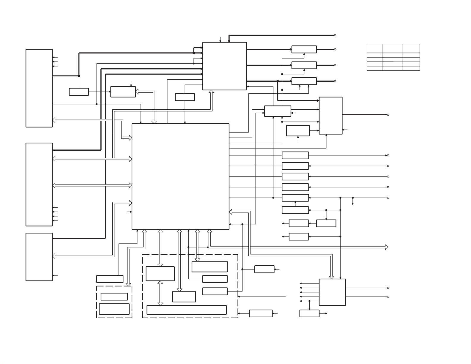
KDC-W 6027/W6027Y
BLOCK DIAGRAM
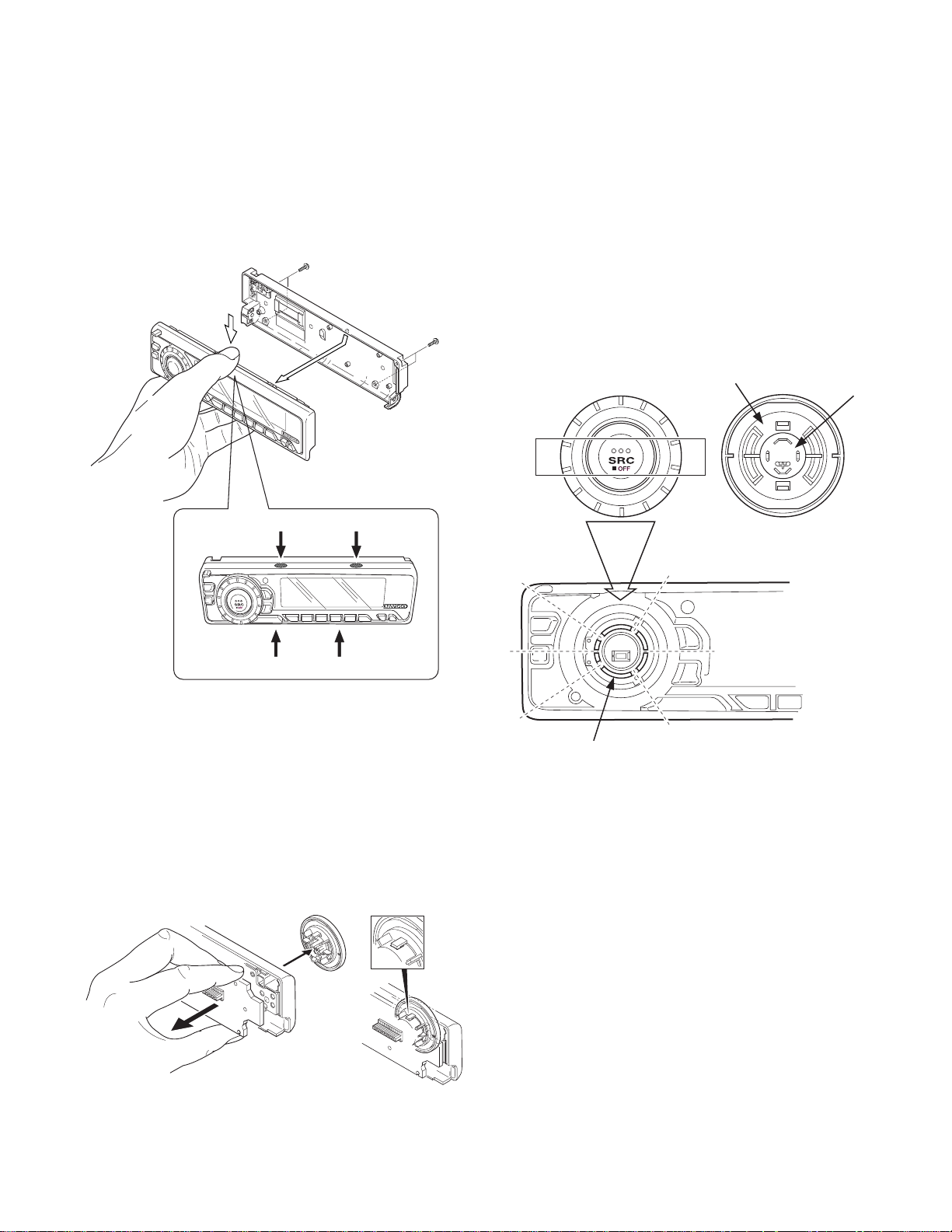
DISASSEMBLY FOR REPAIR
KDC-MP425/MP6026
KDC-W6027/W6027Y
How to Disassemble (PANEL ASSY)
1)Remove four screws (A).
2)While holding the section (B) indicated with arrows, pull and
remove PANEL ASSY.
x2
A
A
B
B
How to install knob (SRC)
1)Place knob (F) and knob (G) in the positions indicated in
the diagram below.
2)While keeping these positions, use a piece of adhesive tape
(H) to hold knobs in position, as shown in the diagarma.
3)Set the rotary (J) position as shown in the diagram.
4)While keeping the letters “SRC” horizontally in position, set
it to the rotary on the panel.
5)Remove the adhesive tape (H).
x2
F
G
H
B
3)Pull SWITCH UNIT (C) as indicated in the diagram and remove knob (D).
(The knob (D) is attached to the rotary with hook (E) and it
is not possible to remove hook (D) only.)
C
B
D
E
J
3
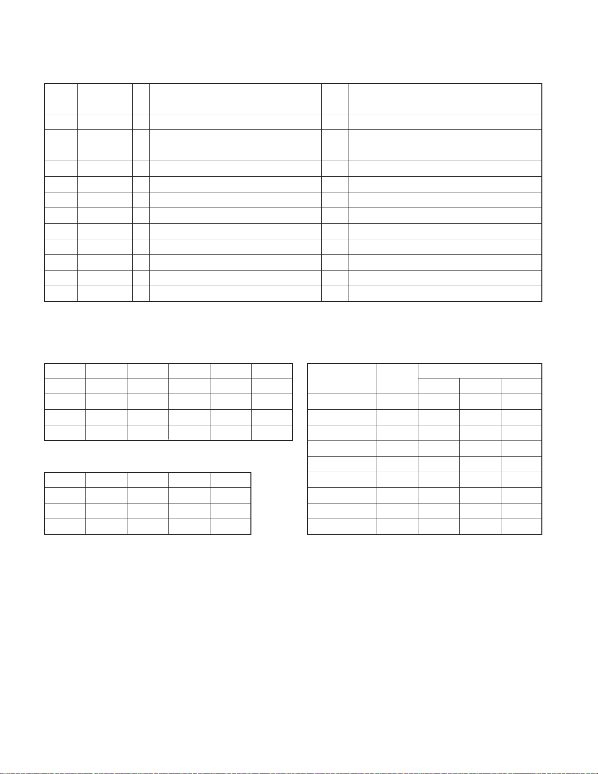
KDC-MP 425/MP6026
KDC-W 6027/W6027Y
COMPONENTS DESCRIPTION
● SWITCH UNIT (X16-2490-10)
Ref. No. Application / Function Operation / Condition / Compatibility
IC1 LCD Driver Drives LCD
IC2 Remote Control IC Controls the unit
Q2 REMO ON SW The power supply of IC2 is turned on when base level goes “L”
Q3 Key Illumination SW (Green) Lights Green key-illumination when base level goes “H”
Q4 Key Illumination SW (Red) Lights Red key-illumination when base level goes “H”
Q5 Dimmer Control Lights LCD Back Light when base level goes “H”
● ELECTRIC UNIT (X34-308x-xx)
Ref. No. Application / Function Operation / Condition / Compatibility
IC1 System µ-COM Controls FM/AM tuner, the changer, CD mechanism, Panel, volume and tone.
IC2 E.Vol & N.C.MPX Controls the source, volume, tone and FM multiplex detector.
Bu5V (5V), Audio8V (8V), FM+B (8V), AM+B (8V), P-CON, ANT-CON
SW1 OUT
1.5~3.0 Audio ON
3.5~5.0 Audio P-CON ON
IC3 Power Supply IC
IC4 Power IC Amplifies the front L/R and the rear L/R to 50W maximum.
IC6 Muting logic IC Controls logic for muting.
IC7 RDS decoder
IC8 Reset IC “L” when detection voltage goes below 3.6V or less.
IC9 SW Regulator Power Supply for MP3
Q1 Serge Detection
Q2 BACK-UP Detection
Q3 ACC Detection “L” when Acc is present.
Q4 SW 5V ON when the base is “L”.
Q21 Servo Regulator
Q22 Servo SW
Q23 Control Power Supply IC
Q31 Dimmer Control Dimmer ON when the base is “H”.
Q41 SW Regulator Control
Q101 Composite signal buffer
7.0~ Audio P-CON, P-ANT ON
SW2 OUT
2.0~3.0 ILL FM ON
4.0~ ILL AM ON
“L” when the back-up voltage becomes more than 24V (momentary power down).
“H” when the back-up voltage becomes less than 24V.
“L” when B.u is present.
“H” when B.u is absent or momentary power down is detected.
4
KDC-MP425/MP6026
KDC-W6027/W6027Y
COMPONENTS DESCRIPTION
Ref. No. Application / Function Operation / Condition / Compatibility
DSI lights when the base is “L”.
Q151 DSI Driver DSI turns off when the base is “H”.
DSI turns on and off when panel is taken off.
Q152 Panel 5V SW
Q153,154 ILL Control ILL lights when the base of Q153 is “H”.
Q201 Noise buffer
Q350
Q351 Pre / NF Mute SW Mutes the Pre Rear Lch or NF Lch when the base is “H”.
Q352 Pre / NF Mute SW Mutes the Pre Rear Rch or NF Rch when the base is “H”.
Q354
Q355 Pre Mute SW Mutes the Front Lch when the base is “H”.
Q356 Pre Mute SW Mutes the Front Rch when the base is “H”.
Pre and NF Mute SW
(not always Pre and NF)
Pre and NF Mute SW
(not always Pre and NF)
When the panel is attached, the base goes “L”, turning the Tr ON to supply 5V to the panel.
When panel is taken off, panel 5V cut off.
Drives the Pre and NF Mute sw (Q351,355) when the base is “L”.
Drives the Pre and NF Mute sw (Q352,356) when the base is “L”.
MICROCOMPUTER’S TERMINAL DESCRIPTION
● SYSTEM MICROCOMPUTER : UPD703030GC044 (X34 : IC1)
Pin No. Pin Name I/O Application
1 PLL CLK I/O CLK output terminal to F/E
2 Not used O
3PANEL-DET I Panel DET terminal No panel DET : L, Panel DET : H
4 IC2 SDA I/O DATA input/output terminal with E-VOL
5 IC2 SCL I/O CLK output terminal to E-VOL
6 VDD 7 VSS 8 FLIP-DET I Flip DET terminal L : Panel DET, H : Panel flippable
9 BEEP O BEEP output terminal
10 REMO I Remote control input
R QUAL I RDS decoder QUAL input terminal
11
Not used O Destination other than E and E2
Truth
Processing Operation Description
value table
5
KDC-MP 425/MP6026
KDC-W 6027/W6027Y
MICROCOMPUTER’S TERMINAL DESCRIPTION
Pin No. Pin Name I/O Application
12
13 L CE O CE output terminal for LCD driver
14 Not used O Non variable illumination switch destination
15 Not used O Non variable illumination switch destination
16 DSI I/O
17 DIM CON O Dimmer control terminal 50ms interval : “H” / “L”
18 TEST 19 ILL CON O During FLIP DET ILL+B OFF During FLIP DET “L” : H
20 VOL A I Volume key input When looking at VOL, also look at FLIPDET
21 VOL B I Volume key input When looking at VOL, also look at FLIPDET
22 MOSW O CD mechanism MOTOR IC SW Loading, Eject, Brake : H
23 LO/EJ I/O CD mechanism LOADING, EJECT switching STOP, Brake : Hi-Z, Loading : L, Eject : H
24 M STOP O STOP request to CD mechanism
25 M RST O Reset output terminal to CD mechanism Normal : H, Reset : L
26 MUTE I/O MUTE terminal Hi-Z : Mute ON, L : Mute OFF
27 LOE/LIM SW I CD DOWN SW DET terminal H : Chucking
28 M-MUTE L I MUTE request terminal from CD mechanism L : Mute request
29 M-MUTE R I MUTE request terminal from CD mechanism L : Mute request
30 PANEL 5V I/O Panel 5V control terminal Panel DET : L, Detached, Momentary power down : H
31 RESET I Normal : H, Reset : L
32 XT1 I 32kHz
33 XT2 I 32kHz
34 REGC - Connect 1µF condenser to GND
35 X2 I 20MHz
36 X1 I 20MHz
37 VSS 38 VDD 39 CLKOUT 40 IC2 TYPE1 I E-VOL setting switching terminal
41 IC2 TYPE0 I E-VOL setting switching terminal
42~44
45
46 SW5V I/O Control terminal for SW5V ON : L, OFF : Hi-Z
47,48
49~51
52 B.U-DET I Momentary power down DET terminal BU DET : L, BU no DET (momentary power down) : H
53 ACC-DET I ACC DET terminal ACC DET : L, ACC no DET : H
R DATA I RDS decoder DATA input terminal
Not used O Destination other than E and E2
EJECT KEY ILL, GUIDE ILL, FLIP-DET “H” and PANEL-DET is “L” : “H” / “L”
DSI control terminal FLIP-DET “H” and PANEL-DET is “H” : “L”
TYPE2~TYPE0
CD MECHA+B
PS2-0, PS2-1
PS1-0~PS1-2
I Destination switching terminal e
I/O Power supply control terminal for MP3 ON : L, OFF : Hi-Z
O Control terminal for power supply IC w
O Control terminal for power supply IC q
Truth
value table
Processing Operation Description
6
KDC-MP425/MP6026
KDC-W6027/W6027Y
MICROCOMPUTER’S TERMINAL DESCRIPTION
Pin No. Pin Name I/O Application
54 DIMMER I Small DET terminal ON : L, OFF : H
55 BVDD 56 BVSS 57 Not used O Non Ext AMP CON destination Output “L”
58 (SVR) O POWER IC SVR control terminal Momentary power down : H
59 P-MUTE O POWER IC MUTE output terminal
60 P-STBY O POWER IC STBY output terminal When POWER IC ON : H, OFF : L
61 Not used O
62
63
64 AFS O Constant switching terminal at noise DET
65
66
67
68 LX_RST O Reset output to external devices
69 LX_CON O Control output to external devices ON : H, OFF : L
70 AVCONT O AD reference voltage control output While in operation : H
71 AVDD 72 AVSS 73 AVREF - AD reference voltage control input Connect to 70 pin
74 PHONE I PHONE DET terminal
75 TYPE3 I Destination switching terminal
76~81 Not used I
82 S-METER I S-meter DET terminal
83 NOISE I FM noise DET terminal
84 IFC-OUT I F/E IFC OUT input terminal
85 LX_MUTE I MUTE request from external devices H : MUTE ON, L : MUTE OFF
86 LX_REQ_M O Request output to external devices Request DET : L
87
88 LX_REQ_S I Request input from external devices Request DET : L
89 KEY-REQ I Communication request from LCD driver L : KEY input
PRE MUTE R
PRE MUTE L
O-DATA I/O External display DATA terminal
Not used O Non external display destination No OPEL DISP : L
O-CLK I/O External display CLK terminal
Not used O Non external display destination No OPEL DISP : L
O-CE I/O External display CE terminal
Not used O Non external display destination No OPEL DISP : L
R-CLK I RDS decoder CLK input terminal
Not used O Non RDS destination Output L fixed
O Rch PRE MUTE output
O Lch PRE MUTE output
Truth
value table
During POWER OFF : L, During ALL OFF : L, When TEL MUTE : L
When momentary power down : L,
M-MUTE R : L (during CD), 2 zone : H fixed
When momentary power down : L,
M-MUTE L : L (during CD), 2 zone : H fixed
During FM seek and AF search : L, During reception : H
Normally : L,
System RST return, then after 400msec or more : H then L
TEL MUTE : 1V or lower,
NAVI MUTE : 2.5V or higher
Processing Operation Description
7
KDC-MP 425/MP6026
KDC-W 6027/W6027Y
MICROCOMPUTER’S TERMINAL DESCRIPTION
Pin No. Pin Name I/O Application
90 LO.S SW I Loading start SW DET terminal Loading start : L
91 12EJE SW I
92 EJECT I EJECT DET terminal L : KEY input
93 Not used O Output L fixed
94 LX_DATA_S I DATA input terminal from external devices
95 LX_DATA_M O DATA output terminal for external devices Last retention
96 LX_CLK I/O CLK input/output terminal with external devices
97 L DATAL I Data input from LCD driver
98 L DATAS O DATA output terminal to LCD driver
99 L CLK O CLK output terminal to LCD driver
100 PLL DATA I/O DATA input/output terminal with F/E
12cm DISC EJECT position DET SW terminal
12 or 8cm DET
Truth
value table
12cm DISC : L
Processing Operation Description
Truth value table
q
PS1-0 PS1-1 PS1-2 AUDIO P-CON P-ANT
LLLOFF OFF OFF
H (L) L (H) L ON OFF OFF
HHLONONOFF
HHHONONON
w
PS2-0 PS2-1 ILLUMI FM+B AM+B
LLOFF OFF OFF
H (L) L (H) ON ON OFF
HHONOFF ON
e
MODEL
KDC-X579 K L L L
KDC-MP425 K H L L
KDC-MPV525 K L H L
KDC-MPV5025 K L L L
KDC-WV6027 E H L H
KDC-W6027 E L L H
KDC-W6027Y E L L H
KDC-MPV7026 M H H L
KDC-MP6026 M L H H
DESTINATION
TYPE
012
8

TEST MODE
KDC-MP425/MP6026
KDC-W6027/W6027Y
1. How to enter the test mode
• While holding the Preset 1 and Preset 3 keys, reset the unit.
2. How to exit from the test mode
• Reset the unit, momentary power down, ACC OFF, power
OFF, and Panel detached.
•(Note) The test mode cannot terminated by Panel is fall
down.
3. Initial status in the test mode
• Sources : All OFF.
•Display : All segments are lit.
•Volume : -10 dB (displayed as 30)
• Loudness : OFF
• CRSC : OFF regardless of the presence of
switching function.
• SYSTEM Q :Flat.
• BEEP :When pressing any keys, the buzzer
generates a beep at any time.
• DISPLA Y TYPE:TYPE A
4. RDS automatic measurement
• An addition to disposal of substitute for visual check PS
display as usual production lines.
• P-CON terminal is OFF by force, when received the PS
data and in case of corrobaration PS display is
“RDS_TEST”. (“_” is mean blank.)
• This disposal is test mode only.
• P-CON is switching the source or return with power on→off.
5. Special display in Tuner mode
When any of the following messages is displa yed in Tuner
mode, the front end may be abnormal.
• “TNE 2P NG”: The EEPROM is set to the default (unstable
values) because the F/E was shipped without passing
through the adjustment process, etc.
• “TNCON NG”: Comm unication with the F/E is not possib le.
7. CD Receiver Test Mode Specification
• When resetting to start, forced ejection of CD is prohibited. When a CD is in place , the CD is not recogniz ed when
reset.
•
When this key is pressed, the mechanism jumps to
the following track.
No9 → No15 → No10 → No11 → No12 → No13 →
No22 → No14 → No9 (Return to the first track.)
• When this key is pressed, the trac k goes down b y one
from the currently played tr ack.
•When a CD being played, by pressing [1] ke y intermittently ,
the mechanism can be made to jump to Track No. 28.
8. Audio-related specifications
•A short press of the Q key initiates the audio adjustment
mode.
• Pressing the ✽ key on the remote initiates the audio
adjustment mode.
•Fader is selected to the initial item.
• Continuous holding of a remote control key is inhibited.
• Bass, Middle and Treble are adjusted in 3 steps of -8/0/+8
with the Track Up/Down keys.
• Balance is adjusted in 3 steps of L15/0/R15 with the Track
Up/Down keys.
•Fader is adjusted in 3 steps of F15/0/R15 with the Track
Up/Down keys.
•Volume Offset is adjusted in 2 steps of -8/0 with theTrack
Up/Down keys.
9. Menu-related specifications
•A shor t press of the MENU key initiates the Menu mode.
Except, tape source is usually press and hold 1 second to
enter the menu mode and short press initiates turn over.
• Pressing the DNPP/SBF key on the remote initiates the
Menu mode.
• Continuous holding of a remote control key is inhibited.
• Contrast is adjusted in 3 steps of 0/5/10 (5x7dot), 0/4/7
(14seg) with the Track Up/Down keys.
6. Forced switching of K3I
• Each press of the Preset 6 key in Tuner mode should switch
K3I from AUT O → Forced Wide → Forced Middle → Forced
Narrow → AUTO. The initial status is AUTO and the display shows these modes as follows.
•AUTO:FMA
•Forced Wide :FMW
•Forced Middle : FMM
•Forced Narrow:FMN
10. Backup current measurement
•When the unit is reset while ACC is OFF (i.e. by turning
Back-Up ON), the MUTE terminal goes OFF in 2 seconds
in place of 15 second.
9
KDC-MP 425/MP6026
KDC-W 6027/W6027Y
TEST MODE
11. Special display when the display is All ON
Pressing the Preset keys while the power is All OFF displays the following information.
[14seg 8 digits]
1key Version display (8 digits, Month/Day/Hour/Min ute)
(Display) xxxxxxxx
2key
3key Short press: View power ON time. (The All OFF
period is not counted.)
Long press/hold: Clear power ON time.
(Display) PONxxxxx Max. 65535 (hours)
4key Short press: Display TAPE operation time.
Long press/hold: Clear TAPE operation time.
(Display) TPTxxxxx Max. 65535 (hours)
5key Short press: Display TAPE ejection count.
Long press/hold: Clear TAPE ejection count.
(Display) EJCxxxxx Max. 65535 (times)
6key Short press: Display Panel open/close count.
Long press/hold: Clear Panel open/close count.
(Display) PCxxxxx Max. 655359 (times)
FM key Display ROM colection version
(Display) ROM Rxxx Invalid :ROM R–
[15x7dot 12 digits]
1key Version display (8 digits, Month/Da y/Hour/Minute)
(Display) SYS_xxxxxxxx
2key
3key Shor t press: View power ON time. (The All OFF
period is not counted.)
Long press/hold: Clear power ON time.
(Display) PonTim_xxxxx Max. 65535 (hours)
4key Short press: Display TAPE operation time.
Long press/hold: Clear TAPE operation time.
(Display) TPTim_xxxxx Max. 65535 (hours)
5key Short press: Display TAPE ejection count.
Long press/hold: Clear TAPE ejection count.
(Display) EjeCnt_xxxxx Max. 65535(times)
6key Short press: Display Panel open/close count.
Long press/hold: Clear Panel open/close count.
(Display) PnCnt_xxxxxx Max. 655359 (times)
FM key Display ROM colection version
(Display) ROM Rxxx Invalid: ROM R–
12. Other specifications
• The line mute against times are 1 second from 10 seconds when starting the test mode.
■ Security
• Forced Power ON mode (All models)
Even when the security is approved, resetting the unit while
holding the Q and 4 keys makes it possible to tur n the
power ON for 30 minutes .After 30 minutes ha ve elapsed, it
is not possible to return to the previous condition unless
the unit is reset again.
• Method of registration of the security code after
EEPROM (F/E) replacement (Code security model)
1. Enter the test mode. (See How to enter the test mode)
2. Press the MENU key to enter the MENU.
3. When the message “Security” is displayed, press and
hold the Track Up/Down key for 1second to enter the
Security registration mode.
4. Enter the code using the FM/AM/Track Down keys.
• FM key : Number up
• AM key : Number down
•Track Up key : Cursor right shift
•Track Down key : Cursor left shift
5. Hold down the Track Up key for at least 3 seconds and
the message, “RE-ENTER” appears , so once again enter the code according to Step 4 above.
6. Press and hold the Track Up k ey f or 3 seconds until “AP-
PROVED” is displayed.
7. Exit from the test mode. (See 2 How to exit from the test
mode)
(Note) All Clear is not applicable to the security code of
this model.
• Simplified method of clearing the security code
1. While the code entry is requested, press and hold the
Track Up key f or 3 seconds while holding the AUTO key
pressed. (----will dissappear.)
2. Enter “KCAR” from the remote.
•Press the 5 key on the remote twice, then press the
Track Up key. (This enters “K”)
•Press the 2 key on the remote 3 times, then press the
Track Up key. (This enters “C”)
• Press the 2 key on the remote once, then press the
Track Up key. (This enters “A”)
•Press the 7 key on the remote twice, then press the
Track Up key. (This enters “R”)
3. Security function is canceled and the unit enters the All
OFF mode.
4. If you commit a mistake in the code entry, the unit enters the code request mode.
10
EDCBA
KDC-MP425/MP6026
KDC-W6027/W6027Y
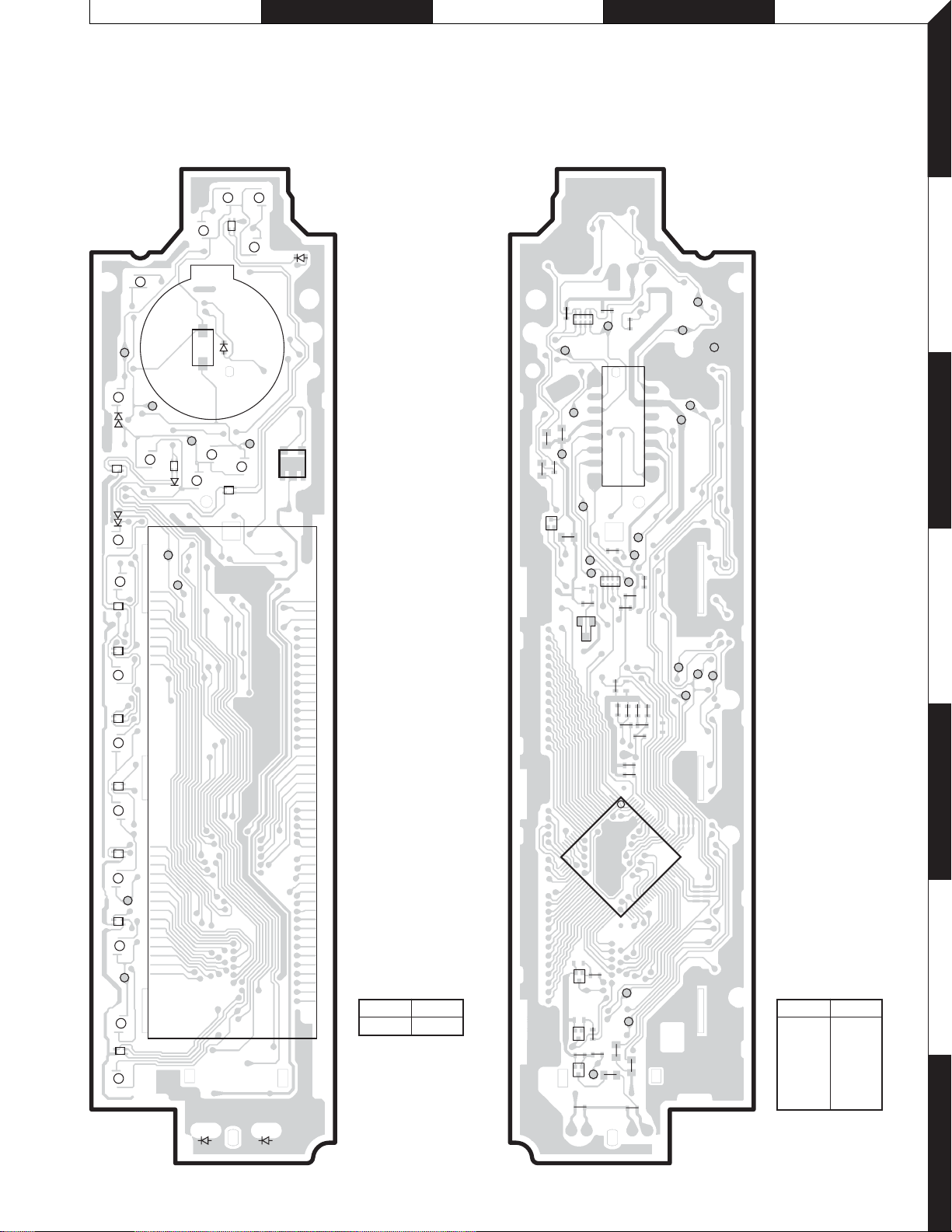
PC BOARD
(COMPONENT SIDE VIEW) (FOIL SIDE VIEW)
SWITCH UNIT
X16-2490-10 (J74-1566-02)
AM
D3
RESET
SRC
KI3
KI4
D6
1
19 10 24
D7
D10
234
D9
D8
S2
KS5
D5
KS4
D1
EQ
D4
KI2
FM
D2
VOL
S1
VCC
VO
KI5
IC2
GND
ED1
69 25
SWITCH UNIT
X16-2490-10 (J74-1566-02)
C11
CP1
C10
VOL A
IFLIP DE
R21
R22
ILL+B
C7
R10
Q2
EB
R23
CLDI
R9
D21
C8
VOL B
2
16
CE
R11
CP2
R3
1
15
J1
REMO
PANEL 5V
DO
R6
R8
R7
C6
R2
C4
C2
C3
R4
R5
R1
C1
1
100
KI4
RESET
ESD-GND
KI5
DGND+ILLGND
KI1
KS4
KI2
KS5
1
2
3
4
5
5
AUTO
6
CLK
D11
D12
D13
KI1
KS3
D32
D31
X16-2490-10
Ref. No. Address
IC2 3B
25
26
IC1
50
51
EB
R14
Q4
KI3
76
75
6
X16-2490-10
Ref. No. Address
R12
BE
Q3
R32
R33
E
B
Q5
C12
R31
DIMMER
R25
C13
R24
KS3
IC1 5D
Q2 3C
Q3 6C
Q4 6C
Q5 7C
Refer to the schematic diagram for the
7
values of resistors and capacitors.
11
 Loading...