

Kenwood KD-CU-5049, KDC-4651-URY, KDC-455-UW, KDC-4551-UB, KD-CU-449 Service Manual
CD RECEIVER
KDC-4551UB/455UW
KDC-4651URY
KDC-U449/U5049
© 2010-12 PRINTED IN JA PAN
SERVICE MANUAL
Tuner setting adjustment after replacing E2PROM
After replacing E2PROM (IC771 on X34), tuner setting adjustment is needed.
The adjustment is that to perform the “TUNER Setting Adjustment Mode” (Page 5)
in the “Tuner Test Mode Specification” of “Production Test Mode”.
B53-0835-00 (N) 223
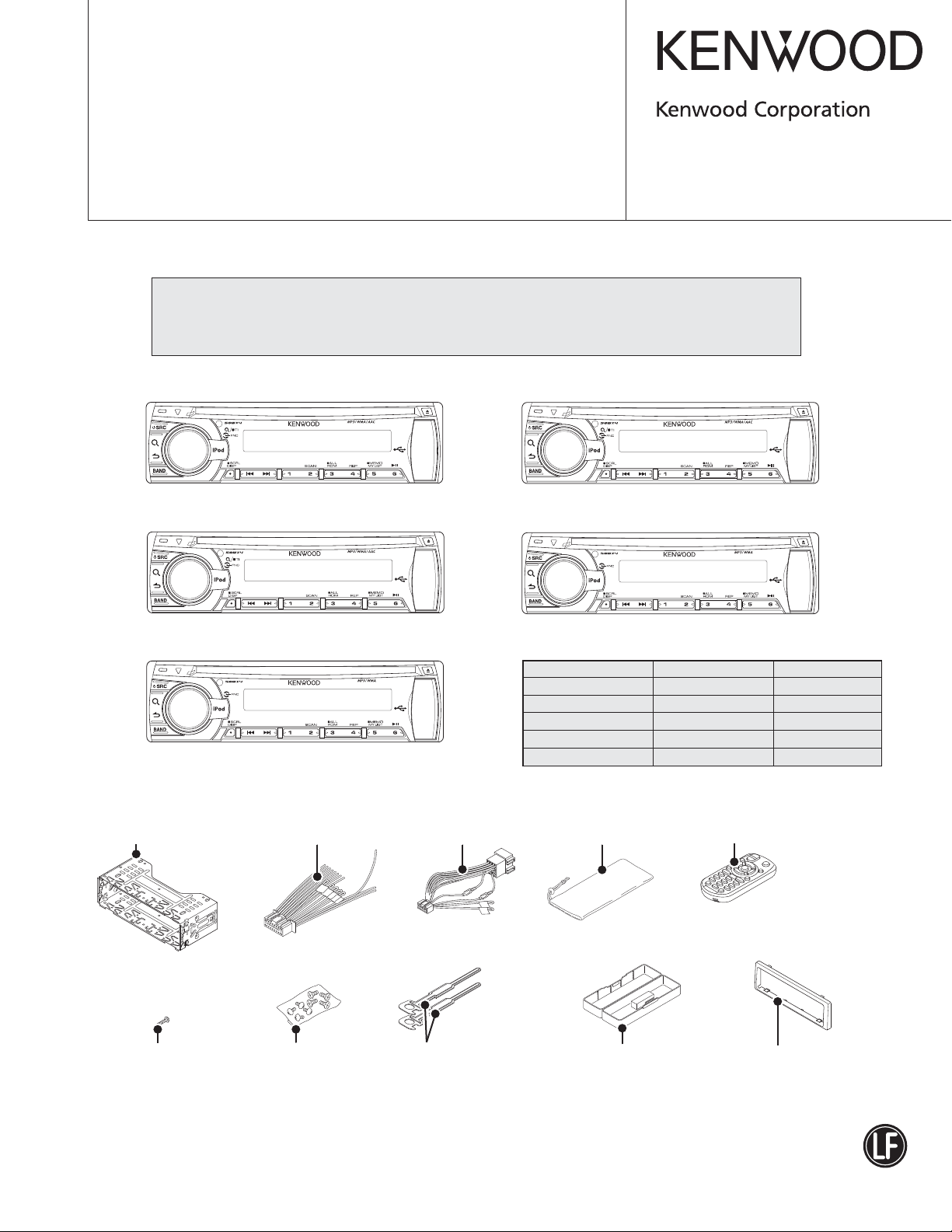
KDC-4451UB : Panel assy (GE20277-001A)
KDC-4651URY : Panel assy (GE20280-015A)
KDC-U5049 : Panel assy (GE20277-010A)
Mounting sleeve assy
(GE34134-001A)
* Car cable
(QAM1341-001)
KDC-4551U
KDC-4651U
KDC-U5049
* Car cable
(E30-6937-05)
KDC-455UW : Panel assy (GE20277-002A)
KDC-455U
KDC-U449 : Panel assy (GE20277-007A)
KDC-U449
TDF SPARE-PANEL
MAIN UNIT NAME TDF PARTS No. TDF NAME
KDC-4551UB Y33-3382-71 TDF-4551UB
KDC-455UW Y33-3382-72 TDF-455UW
KDC-4651URY
KDC-U449
KDC-U5049 Y33-3383-01 TDF-U5049
* Carrying case
(W01-1710-05)
Y33-3382-73 TDF-4651URY
Y33-3380-21 TDF-U449
* Remote control unit (RC-405)
(A70-2104-05)
* Tap screw (2x8)
(N80-2008-43)
* Depends on the model. Refer to the parts list.
* Screw set
(N99-1757-15)
Hook
(GE40510-001A) x2
This product complies with the
* Hard case assy
(A02-2757-13)
This product uses Lead Free solder.
Trim plate
(GE20274-001A)
RoHS directive for the European market.
KDC-4551UB/455UW/4651URY
2
KDC-U449/U5049
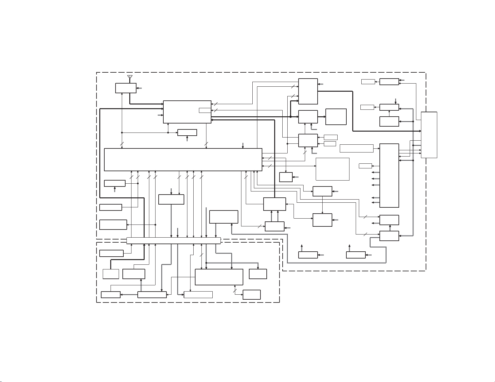
ELECTRIC UNIT (X34- )
IC1
IC701
IC702
RESET IC
BU3.3V
S701
RESET SW
to DC
CONNECTOR
EXT REMO
(OE REMOTE)
CN701
CN601
to GND
PANEL DET
J1
TUNER
ATOMIC
2
ANT
A9V
12
IC161
BU5V
PANEL3.3V
E-VOL
IC771
E2PROM
BU3.3V
111
22
USB5V
A9V
SYSTEM u-COM & USB HOST
Q701
PANEL3.3V
(REMO DRV)
CONNECTOR
MUTE
1
5
5
1
1
ILLUMI+B
R902,903
LOAD
RESISTOR
(FL FILAMENT)
FL+B
FL+B
BU3.3V
8
3
9
IC540
SERVO IC
(OASIS)
CD1.5V CD3.3V
IC530-532
1
CD 3.3V
CD 1.5V
i-Pod
CP
IC80
2
1
∗
∗
Q780
BU5V
SW3.3V
IC301
POWER
AMP
Q321,341
RCA
MUTE
MUTE
2
SW3.3V
to MECHA
Q951,952
SW 3.3V
BU
∗
J321
RCA-OUT
BU5V
BU DET
RESET
BU3.3V
DC-CN etc
PHONE
ACC5V / BU-DET
PON-FL
PS1-1 / PS1-2 / PS1-3
PS2-1 / PS2-2
IC501
MOTOR
DRIVER
CD
MECHA
VDD3.3V
PS1-1 / PS1-2 / PS1-3
PS2-1 / PS2-2 P-ANT
ACC5V
ILLUMI+B
AUDIO
CD
CD3.3V
USB5V
BU3.3V
IC931
SW 3.3V
PHONE
BU DET
SW5
CD
BU5V
2
2
FL+B
BU5V
D891
PHONE
Q970
BU DET
Q971
SURGEDET
IC901
POWER
SUPPLY
IC
IC961
HI-SIDE
SW
IC981
USB5V
(DC/DC)
BU3.3V
SW3.3V
CN901
DC-CN
PHONE
SP-OUT
ACC
BU
P-CON
BLOCK DIAGRAM
J602
IC602
EN601 FL601
F-AUX
REMO
ROTARY
ENCODER
SW3.3V
SW3.3V
SWITCH UNIT (X16- )
Q602
PANEL SW3.3
USB CN
CN603
KEY
FL
9
ILLUMI
KEY
MATRIX
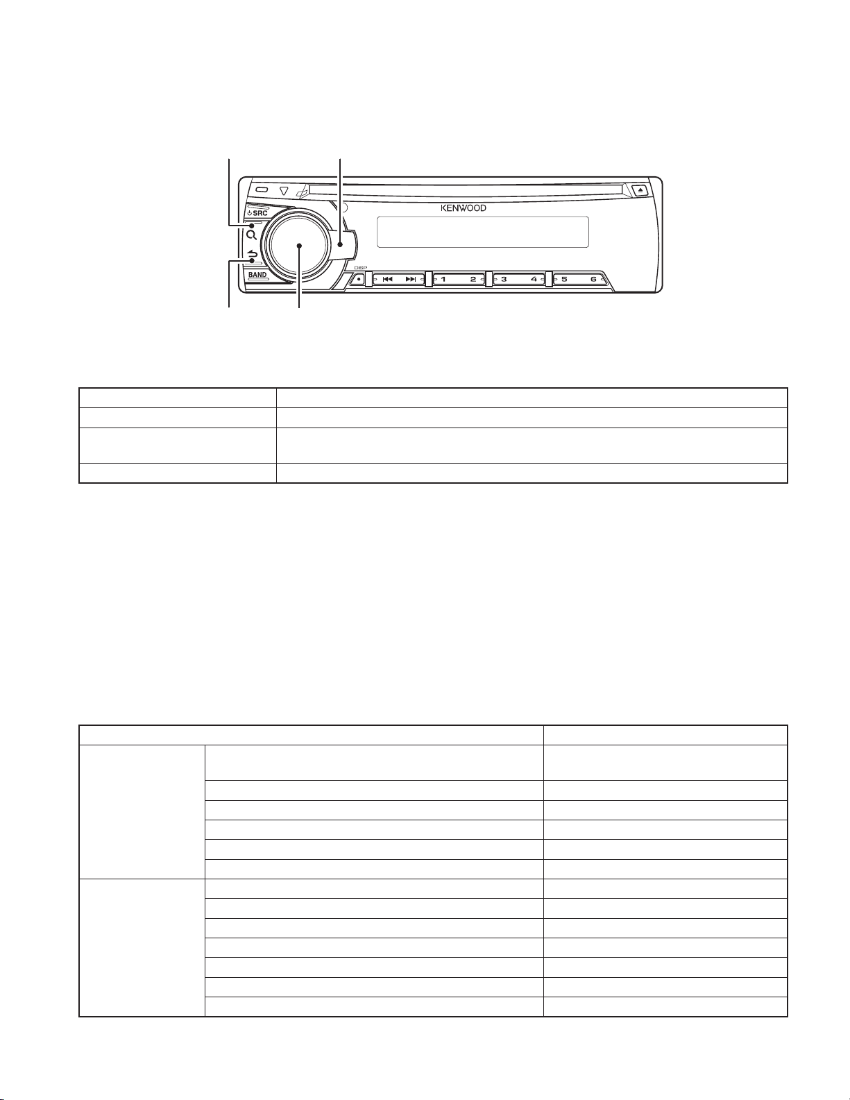
1. Panel
SEARCH
KDC-4551UB/455UW/4651URY
KDC-U449/U5049
TEST MODE
ACCENT
RETURN
VOL
2. How to enter each Test Mode
Test Mode name Operation
Production Test Mode Press and hold [1] key and [3] key and reset.
Service Test Mode
DC Error Information Mode Press and hold [3] key and [6] key and reset.
Transition to Test Mode shall be available during DC Error detection.
✳
In the STANDBY source, while pressing and holding [2] key, press [6] key for 7 seconds.
(Starting to press [2] key and [6] key at the same time can not be entered into the mode)
3. How to release each Test Mode
• Reset
• Momentary voltage drop
• ACC OFF
• POWER OFF
• Panel Detach
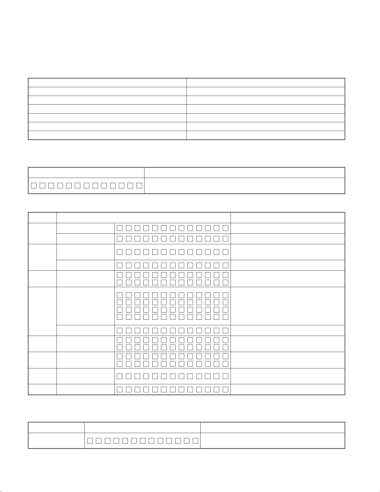
4. Production Test Mode
Default status immediately after the mode activation
●
It shall be same as normal RST start in other than the below setting.
Details
Period to prohibit TEL/LINE MUTE immediately after activation
(normally 10 seconds)
Mecha Initialize Action Prohibited
Difference in action
Various setting value
Write-in to E2PROM when detecting a DC error Prohibited
Demo Mode ON/OFF Setting Menu Prohibited
Power supply during ACC OFF (Back Up On) MUTE terminal turns OFF after 2 seconds
BEEP sound Beep with short-pressing in any functions
Volume 30 (-10dB)
BASS BOOST/LOUD OFF
EQ NATURAL
Fader/Balance Center
DEMO Mode Setting OFF
AUX Setting ON1
NAVI MUTE Setting for Japan Detecting function valid (ATT)
1 second
3
KDC-4551UB/455UW/4651URY
KDC-U449/U5049
TEST MODE
Mode structure
●
Some Test Modes change according to the current source.
The following table shows the current source in Set and the related test mode status.
KWD model source Test mode
POWER OFF -
Standby STANDBY Test Mode
TUNER TUNER Test Mode
CD CD Test Mode
USB -
AUX -
Mode content
●
Syscon shall display the following information after entering this mode. The operation shown below shall be workable.
Display content Details
PRO TEST
The display is released when another operation is executed.
The display will blink if sub clock is not functioning.
STANDBY Test Mode Specifi cation
●
Operation Display content Details
1 (Toggle)
2 (Toggle)
3 (Toggle) All lights ON/OFF
4 (Toggle)
5 (Toggle) Preout switch
6 (Toggle) All lights ON/OFF All lights ON/OFF with toggle
SOURCE
Transition
RETURN Mode release
■
Syscom version display
All lights ON All lights ON (Switch to other display)
Serial No. display
All lights ON
Information display iPod
verifi cation IC mount
status display
All lights ON
Mode release Return to Normal mode
SN :00000000
iPod :
iPod :OK
iPod :NG
iPod :
SWP R E R E A R
SWP R E S UB –W
SYS0∗–
∗∗∗
∗∗
Syscom version (Refer to Syscom Version Table)
Serial No. display (8-digit)
Display as it is in hex
✳
All lights ON (Switch to other display)
All lights ON/OFF with toggle
iPod verifi cation IC mount status display
Blank: Verifying
OK: Verifi cation IC mounted
NG: Verifi cation IC not mounted
: Non-iPod support model
∗∗
All lights ON (Switch to other display)
Switch Preout with Toggle
(1Preout/2Preout model only)
Return to Normal mode
Tuner Test Mode Specifi cation
●
The following displays shall be indicated according to the TUNER status.
Status Display content Details
TUNER IC
Communication error
TUN CON NG
4
Communication to TUNER IC not available (indicated unless
the mode is in Clock Display Mode).
Status Display content Details
Adjustment not
implemented
RDS Specifi ed data
reception
Operations
Operation
ACCENT
BAND
SEARCH
DISP
■
TUNER IC
display
4 Preset operation
BAND switch
operation
S meter voltage
judgment display
Shift to TUNER
setting mode
TEST MODE
ERR
∗
RDS T E ST
ATOM RDS
FM1 – 3 A 9 7.9 A
FM1 – 3 A 9 7.9 A
S–MTR xx:OK
S–MTR xx:NG
S–MTR xx:––
∗
Display content Details
A97.9A
KDC-4551UB/455UW/4651URY
KDC-U449/U5049
For models that TUNER adjustment is necessary but not done
(adjustment value: 0x00 or 0xFF), the following TUNER Test
Mode functions are valid (“∗ERR∗” display is continuing).
Display “∗ERR∗” blinks with 250ms interval.
Turn OFF P-CON forcibly if PS=RDS TEST is received.
P-CON recovers with Power OFF/ON.
Display TUNER IC version
Display content is assigned by Tuner Development G.
✳
Switch to either 98.3 (except for J type)
Execute Band Switch as shown in the following table
every time Band key is pressed in each type.
S meter value xx: Current S meter value
Determination result OK: Within S meter voltage spec
NG: Out of S meter voltage spec
– – : No LEVEL OFFSET adjustment
Transit to TUNER setting adjustment mode after switching
to 98.3MHz
Frequency: 98.3MHz, Modulation frequency: 1kHz,
Modulation mode: MONO, Modulation: OFF,
Deviation: 40kHz, ANT input level: 34dBμV
TUNER Setting Adjustment Mode
1. Operation (Operation after performance of above-mentioned “Shift to TUNER setting mode” item)
Operation Display content Details
Select TUNER adjustment method (A: AUTO) us-
ing BAND key.
BAND
■
(Toggle)
AUTO Adjustment
Mode
A S–xx L–xx
S-xx: Current S meter value (Hex)
L-xx: Level offset value (Hex)
In case that the level offset value is not ad-
✳
justed (0xFF or 0x00), display “– –”.
2. Operations in AUTO Adjustment Mode
Operation Display content Details
Start Adjustment (Start Auto adjustment, and
VOL PUSH Adjustment start
A S–xx L–xx
transit to Success/Failure display depending on
the adjustment result)
3. Status display during adjustment
Status Display content Details
Adjustment success
Adjustment failure
ADJ OK :x x
ADJ NG
When the adjustment value write-in to E2PROM (IC771 on X34)
has been completed. xx: Level offset value (HEX)
When the adjustment value write-in to E2PROM (IC771 on X34)
has failed.
5
KDC-4551UB/455UW/4651URY
KDC-U449/U5049
TEST MODE
4. Operation of return to TUNER Test Mode
Operation Display content Details
RETURN Mode release Return to TUNER Test Mode.
BAND switch list
●
Type BAND1 BAND2 BAND3 BAND4 BAND5 BAND6 Details
E
M/C
CD Test Mode Specifi cation
●
It shall be the same as normal RST start in other than the below setting.
Playback track from top No.9
Default for Display mode Play time
FM1 FM2 FM3
q
FM1 FM2 FM3
q
Content Details
MW/LW - -
w
MW
w
e
SW1
r
SW2
q→w→q
q→w→e→r→q
…
…
Operations in CDDA playback
Operation
Special track up
Special track
down
CD HC1
CD HC2
CD
C D 0 1: 1:2 3
1
(Toggle)
3
4
5
6
HC1/2 Judge-
ment Information
Display
Normal Display
Special jump
operation
Special jump
operation
Special jump
operation
Special jump
operation
Display content Details
Pressed Track up depend on different cases.
Case 1: Track>23 No.9→No.15→No.10→No.22→No.12
No.13→No.14→No.9
→
Case 2: Track<8 No.1→No.2→No.3→Until Last Track
Case 3: 8<Track<22
No.9→No.15→No.10→Until Last Track
One-by-one Track down by sequence follow Track No.
HC1/2 Judgement Infomation.
HC1: HC1 mecha (for this model)
∗∗∗
HC2: HC2 mecha
: Impossible of Judgement
∗∗∗
Normal Display
Jump to No.28
(Scratch 0.7mm for MUSIC line vibration test)
Jump to No.14 (Damaged disc TCD-731RA Tr14)
Jump to No.15
Set Volume value at 26 (for error operation FCT check of
20Hz 0dB DC protection)
Jump to No.9 if the other than track No.9 is playing.
Jump to No.22 if the track No.9 is playing.
5. Service Test Mode
Default status immediately after the mode activation
●
It shall be same as the normal activation.
Mode structure
●
Service Test Mode is enabled only STANDBY source.
6
KDC-4551UB/455UW/4651URY
KDC-U449/U5049
TEST MODE
Mode content
●
Syscon shall display the following information after entering this mode. The operation shown below shall be workable.
Display content Details
SRV T EST
Common operation mode for only STANDBY sources
●
Operation
1
3
4
5
5
■
■
Development name
status display
Power ON duration
display
Disc action duration
display
Disc Eject number
of times display
Disc Eject number
of times clear
Forced Power OFF
information display
Forced Power OFF
info clear
Display content Details
1011WE –200
PONTM 0H x x
PONTM xxxxx
CDTM 0 Hx x
CDTM xxxxx
EJCNT xxxxx
POF F – – –
POF F PNL
The display is released when another operation is executed.
Development name – Version (Micom)
00~50 are displayed in “xx”.
For less than 1 hour, the display is indicated per 10
minutes.
00001~10922 are displayed in “xxxxx”.
MAX 10922 (hours)
0~50 are displayed in “xx”.
For less than 1 hour, the display is indicated per 10
minutes.
00001~10922 are displayed in “xxxxx”.
MAX 10922 (hours)
Display Disc Eject number of times.
MAX 65535 (times)
Clear Disc Eject number of times by pressing for 2
seconds when it is displayed.
No forced Power OFF
Forced Power OFF due to Syscon-Panel communica-
tion error.
Clear forced Power OFF information by pressing for 2
seconds when it is displayed.
CD Error Information Display Mode
●
Operation
DISP
Move
between
BAND
(Forward
search)
items with
/
CD error information
display mode
CD Mech error log
display
CD Load error info
display
CD Eject error info
display
CD time code error
count information
display (count skip)
Display content Details
MECH A ER #:x x
LOAD ER#:x x
EJECT ER#:xx
CNT LOSE
CDDA :x x
CDROM :x x
Transit to CD error information display mode.
Mech error history 1,2,3 (latest)
#: History No. (1,2,3)
xx: numbers of errors, “--” when there is none
Load error switch 1,2
#: Switch No. (1,2)
xx: numbers of errors, “--” when there is none
Eject error switch 1,2,3,4
#: Switch No. (1,2,3,4)
xx: numbers of errors, “--” when there is none
CD time code error count information (count skip)
mode display
CD-DA error count numbers
xx: numbers of errors and “--” when there is none
CD-ROM (compressed fi le) error count numbers
xx: numbers of errors and “--” when there is none
7
KDC-4551UB/455UW/4651URY
KDC-U449/U5049
TEST MODE
Operation
Move
between
BAND
(Forward
search)
items with
/
DISP
■
DISP Mode release CD error information display mode release
CD time code error
count information
display (no count
update)
CD error information
clear
Display content Details
CNT ST A Y
CDDA :x x
CDROM :x x
CD time code error count information (count not up-
dated) mode display
CD-DA error count numbers
xx: numbers of errors and “--” when there is none
CD-ROM (compressed fi le) error count numbers
xx: numbers of errors and “--” when there is none
CD error information all clear
6. DC Error Information Mode
Default status immediately after the mode activation
●
It shall be same as normal activation.
Mode structure
●
DC Error Info Mode is enabled regardless of current source.
Mode content
●
Syscon shall display the following information after entering this mode. The operation shown below shall be workable.
Display content Details
D
CERR
DC OK
When DC error is detected (in case that one of capacitor leakage, wrong connection or
other detection is found)
When DC error is not detected (in case that none of capacitor leakage, wrong connec-
tion or other detection is not found)
Mode operation specifi cation
●
Operation
1 DC ERR1 display
1 DC ERR1 clear
■
2 DC ERR2 display
2 DC ERR2 clear
■
Display content Details
DC1 ERR
DC1 OK
DC1 OK
DC2 4
DC2 0
When wrong connection & DC error in other detection
duration is detected
When wrong connection & DC error in other detection
duration is not detected
Clear detection information when wrong connection &
DC error in other detection duration is displayed. (Clear
data fl ash)
Display detecting number of times in capacitor leakage
detection duration (0~4)
Clear number of times for detection information in ca-
pacitor leakage detection duration. (Clear data fl ash)
7. FM/AM Channel space switching (Except models for destination “E”)
Procedure Note
While Power OFF, pressing and holding [1] key and [5] key, and press [SRC]
key to Power ON.
8
FM200kHz/AM10kHz ↔ FM50kHz/AM9kHz
EDCBA
KDC-4551UB/455UW/4651URY
KDC-U449/U5049
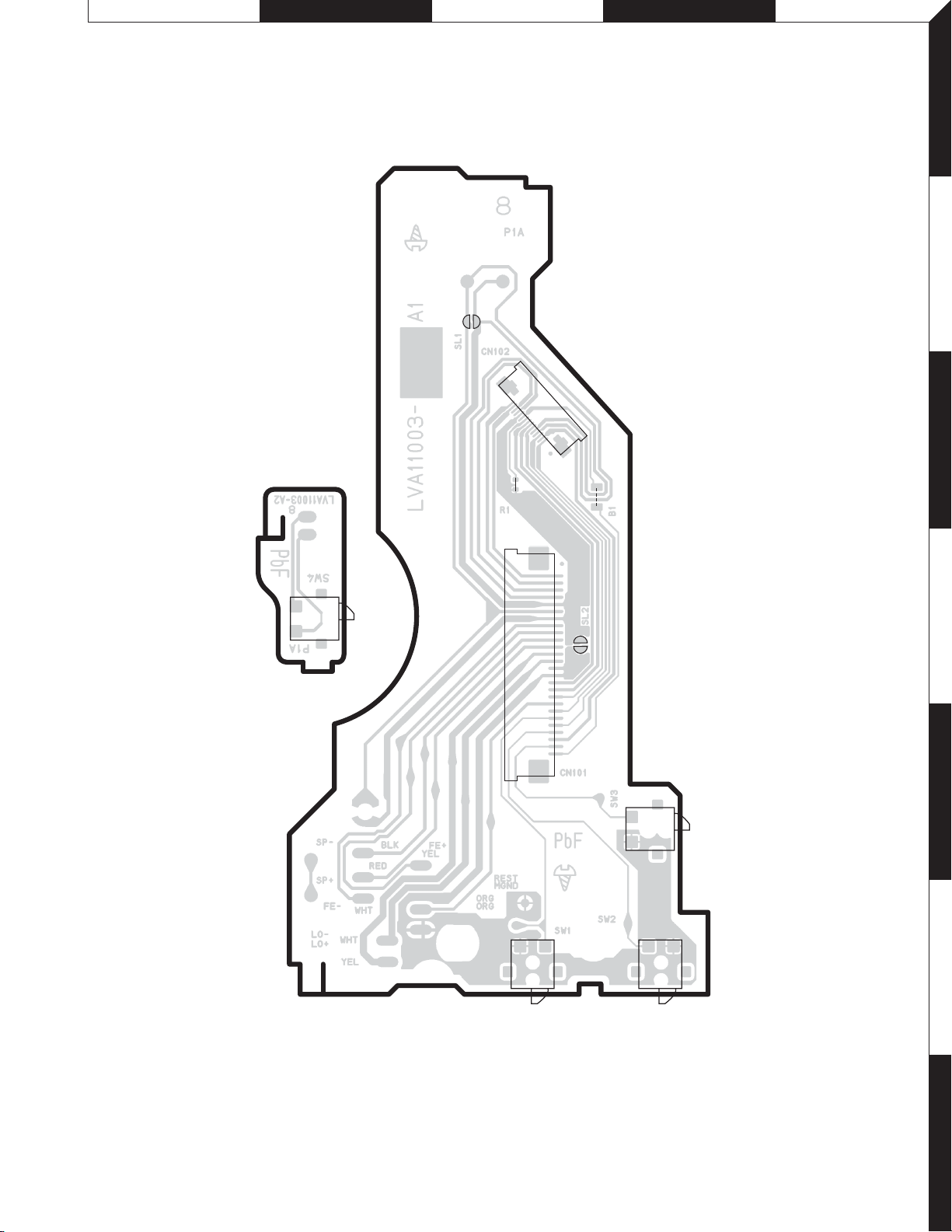
PC BOARD (FOIL SIDE VIEW)
CD PLAYER UNIT
X32-6430-00 A/2 (LVB11003-001A)
X32 B/2
SL1
CN102
1
2
15
1
R1
B1
3
SW4
SPBLK
SP+
RED
FE-
WHT
LO-
WHT
LO+
YEL
FE+
YEL
REST
ORG
MGND
ORG
1
4
SL2
CN101
26
5
SW3
SW2SW1
6
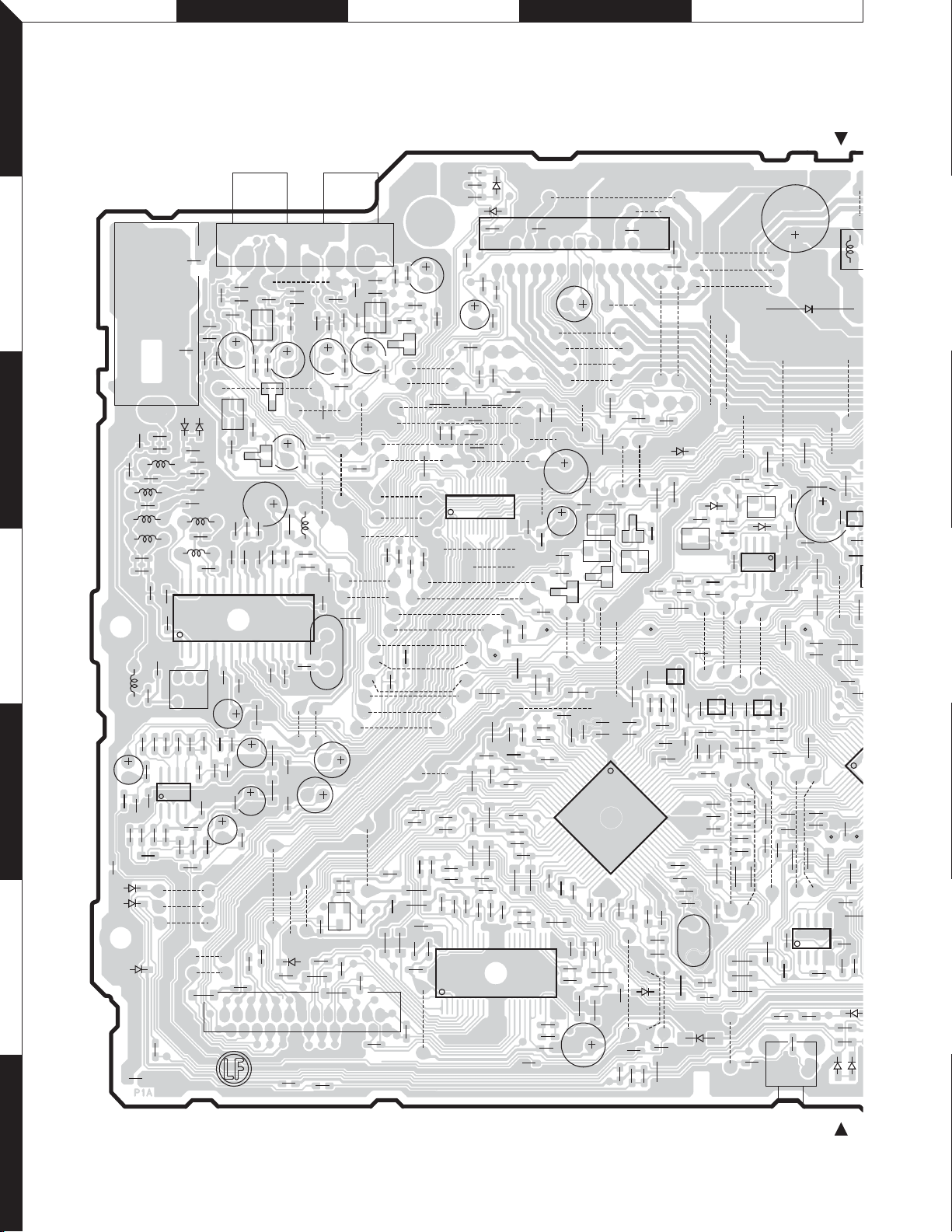
Refer to the schematic diagram for the values of resistors and capacitors.
7
9
0
3
4
4
L702
W
F G H I J
KDC-4551UB/455UW/4651URY
KDC-U449/U5049
1
2
3
4
5
6
PC BOARD (FOIL SIDE VIEW)
ELECTRIC UNIT
X34-691x-xx
(GEB10301-201A)
R4
C19
C591
C590
R576
CBE
EBC
R357
C18
R596
R342
D321
R251
C22
R577
R358
R5
C14
R416
B551
PRE OUT
C341
R341
Q321
C340
C251
R11
R8
C15
R594
C592
C593
R583
B532
D540
R550
C102
J321
B313
R340
B314
L7
R6
R7
16
C20
B2
B533
R413
CN502
C254
R343
R323
B3
C508
C101
R332
R256
B170
R534
R258
C252
R333
C8
C21
C174
R546
R547
EB
Q540
R414
R330
R254
B311
R417
C509
C331
R331
R324
X1
C162
C330
B192
B4
B5
B534
C550
C510
C512
C351
R351
CBE
EBC
25
B173
R165
R548
R502
26
R352
R334
B169
B171
B172
C173
B184
B185
C551
R349
Q341
B165
B166
B167
R163
R503
C586
R459
ANTENNA
J1
C28
L8
C26
L1
C2
L9
L2
C27
R3
L3
R586
C583
R593
R585
D102
D112
D113
R490
C368
R322
R320
C253
R257
R373
R255
R253
Q251
CBE
D1
D2
1
L4
4
R528
R581
R580
R1
C29
C6
L6
R599
R582
C1
R2
L5
C12
C595
R575
C11
R529
C584
C594
B552
B531
R589
C582
EBC
C24
C23
R587
R590
1
L10
R9
R10
32 17
C3
C10
C4
C7
C5
R591
R579
C587
R592
85
R595
IC580
1
C588
R597
R598
C585
B527
B528
B529
C111
C321
R321
C320
B521
R252
C17
C16
IC1
R588
R584
R468
2
D251
C13
C25
R305
R780
C314
D782
D341
B163
B164
R162
R353
R310
C170
C350
C171
TH301
C310
R461
C316
C169
R168
C308
C168
R350
R347
IC161
B174
R167
R161
C161
B181
C575
C576
R412
R411
R520
B180
B182
R506
R519
C503
C511
B176
B177
B178
B179
R723
B183
R541
B503
R402
R545
R549
C553
R552
R512
C515
R467
C557
C556
C501
R517
C504
C516
36 19
R501
1
B535
C318
C160
R477
C177
C543
IC301
C172
R531
R510
C506
C309
B189
R404
R532
R513
B301
C178
D781
C542
R515
C514
B305
B304
B303
B302
Q781
Q780
B190
R540
R533
R507
B309
R491
B191
C540
C541
40
C517
R518
C518
R504
R306
R401
R783
EB
EB
1
IC540
R553
B306
B187
B542
C574
C573
80
41
C561
R728
R111
C312
Q782
D301
C311
R781
24 2
25 1
R303
R304
C313
C307
C317
R400
C319
B315
B168
1528
B186
141
C166
L161
B175
D780
R478
SDA
L12
L11
SCL
R432
R726
R722
B543
C544
C545
R403
C546
C547
C548
C549
R542
R544
R543
20
C552
R505
C558
C554
C555
R509
C505
R516
R508
21
C559
R410
R406
R551
R511
IC501
18
C507
R514
C513
C560
C305
R405
B536
C563
R101
B310
B188
EB
L562
D503
C100
D783
C727
RST
C534
C572
L561
R554
R555
B307
C306
R447
R574
C570
C568
B537
C596
R415
R307
R784
R573
C562
B308
D132
R302
R754
R779
R418
R471
21
34
C571
61
60
C565
C564
R557
B538
C315
R558
R492
R974
EB
Q971
IC532
C535
C569
D502
R753
C532
R463
C567
R570
L563
X540
L531
R462
B908
D971
R778
B793
IC531
21
34
R572
R566
C566
R565
B921
B920
R971
R973
B792
R571
R562
R556
B919
B925
B912
R481
Q970
R972
D970
41
IC771
R787
58
B791
IC530
C533
C530
R530
R409
R408
B540
B539
R568
R567
R569
L565
L564
R564
R563
R708
R713
R715
B762
C706
R970
EB
B790
21
34
R560
R446
R465
R466
R464
B541
R485
R736
C110
S701
R727
R731
C901
D901
B901
R976
R975
C723
R904
R426
C531
R559
R749
R735
R422
R451
C932
C954
R479
R450
R718
SN
R742
R744
R739
B760
B761
C713
R740
SWDIO
R428
R561
85
IC80
14
R82
R110
R745
B911
R445
R430
L901
C931
B789
R439
R440
C714
50
51
R752
C80
R751
R102
R100
D101
B924
R444
R741
R431
D11
IC9
21
34
R48
R7
S
R429
R750
D100
B933
R443
Q951
R701
7
10
 Loading...