

Kenwood KDC-715S, KDC-8016, KDC-8015 Service Manual
CD RECEIVER
KDC-715S/8015
Q
Q
3
7
6
3
1
5
1
5
0
KDC-8016
SERVICE MANUAL
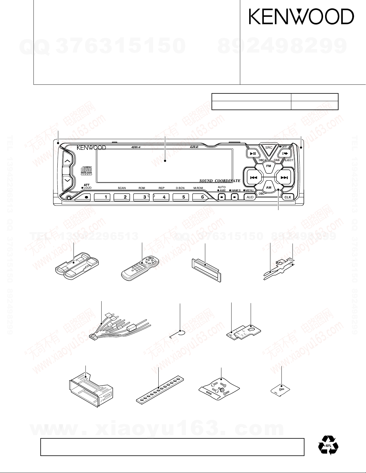
Illustration is KDC-715S
Escutcheon assy
(B07-2139-03)
TEL 13942296513 QQ 376315150 892498299
Front grass
KDC-715S : (B10-3112-01)
KDC-8015 : (B10-3111-01)
KDC-8016 : (B10-3114-01)
KDC-715S
4
2
9
8
© 2000-1 PRINTED IN JAPAN
B51-7570-00 (N) 1789
Extension cord Parts No.
CD mechanism (22P) W05-0618-00
Panel assy
KDC-715S : (A64-1872-02)
KDC-8015 : (A64-1871-02)
KDC-8016 : (A64-1874-02)
DISP
Dressing panel
(A21-4010-03)
9
8
2
9
9
TEL 13942296513 QQ 376315150 892498299
TEL
Plastic cabinet assy
13942296513
(A02-1489-03)
DC cord
(E-30-4780-05)
Mounting hardware assy
(J21-9491-03)
Remote controller assy
(A70-0883-05)
Torsion coil spring
(G01-2924-04)
Stay
(J54-0606-04)
Escutcheon assy
3
Q
Q
(B07-2183-02)
5
1
3
6
7
Bracket
(J19-4876-04)
Screw set
(N99-1652-05)
Lever
8
0
5
1
(D10-4301-14)
Bracket
(J19-4875-04)
Screw set
(N99-1683-05)
Lever
9
4
2
9
(D10-4302-14)
8
2
9
9
w
w
w
The MECHANISM OPERATION DESCRIPTION is the same as model KDC-S3007 and KDC-5050RG.
Please refer to the service manual for model KDC-S3007 (B51-7029-00) or KDC-5050RG (B51-7099-00).
.
xia
o
y
u
1
6
3
.
c
o
m
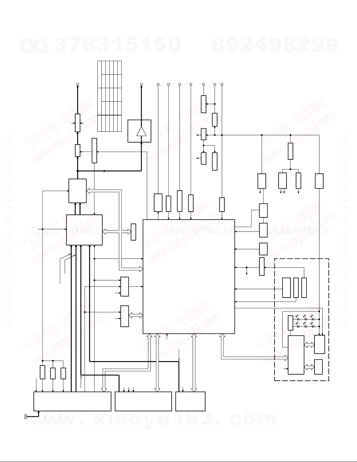
KDC-715S/8015/8016
COM+B
FM+B
AM+B
E2PROM
DIMMER
2WAY MUTE
ACC DET.
SRM
PHOT
BU DET.
SRM
DRIVER
A8V
SERVO
DC/DC
SW14V
SW5V
BU5V
P CON
ANT-CON
MUTE DRIVER
4.5V PRE
MUTE
E's
POWER IC
IC4
IC14
u-com
IC1
CD
CH
IC10
IC7-9
IC5
IC2
F/E
MECHA
DET.
E-VOL
PREOUT
SP-OUT
DIMMER
TEL-MUTE
ACC
ANT-CONT
P-CON
BACK UP
DECORDER
RDS
IC11
EX.AMP CONTROL
AVR
RESET IC
IC15
ANT. IN
AMP
IC12
NOISE
PREOUT OUTPUT VOLTAGE
CONTROL
EX.AMP
NAVI-MUTE
PANEL 5V
4.5VPRE
IC3
IC6
ILLUM
+B
LCD
LCD CONT. 1
G/R SW
KEY
MATRIX
LCD TYPE
LOCK SW
PANEL
REMO
RESET SW
PLL CLK
CH
MO SW
SERVO+B
LO/EJ
STOP
MUTE
DATA S
CLK
SW2
CS
SQR
DATA M
SW3
SW1
A8V
BU5V
RST
REQ C
CLK
CH-CON
DATA H
REQ H
CD
AM
FM
MUTE
RESET
SRM SW1
SRM DET
SRM SW2
RDCK
RDDA
QUAL
SDA
SCL
A8V
+B
-B
+B
-B
PLL DATA
PLL CE
S-METER
SW5V
SW5V
DATA C
BACK UP
750mV
4500mV
CHANGER
AM
4.5V PRE
2250mVFM
160mV
1200mV
1200mV
213mV (E TYPE)
400mV (K TYPE)
RDS OUT
FM+B
NOISE
4500mVCD
K TYPEMODE
4500mV
4500mV
1069mV
1715mV
E TYPE
3600mV
600mV
1800mV
3600mV
K TYPE E TYPE
3600mV
1372mV
855mV
3600mV
1.8V PRE
SRM SUBSRM SUB+
DRIVER
MUTE
BU5V
PANEL 5V
DIMMER PWM CONTROL
ILLUM +B IS LCD ONLY
RST
L DATAL
L CLK
L CE
L DATAS
DIMMER
(X86)
BLOCK DIAGRAM
Q
Q
3
7
6
3
1
5
1
5
0
TEL 13942296513 QQ 376315150 892498299
8
9
2
4
9
8
2
9
9
TEL 13942296513 QQ 376315150 892498299
TEL
13942296513
Q
Q
3
7
6
1
3
5
1
0
5
9
8
2
9
4
8
2
9
9
w
w
w
.
xia
o
y
u
1
6
3
.
c
o
m
2
KDC-715S/8015/8016
MICROCOMPUTER’S DESCRIPTION
7
Q
Q
System µ-com : UPD784217GC (X25-)
Terminal description
No. Pin name Function I/O Description Processing Operation
TEL 13942296513 QQ 376315150 892498299
TEL
w
3
1 P120/RTP0 CHCON1 O Changer 1 control Active : Hi
2 P121/RTP1 CH_MUTE I Changer muting input MUTE Requested : Hi
3 P122/RTP2 REQH O Handshake request to changers Active : Lo
4 P123/RTP3 ILL_ON O Illumination output Active : Hi
5 P124/RTP4 NC O Open
6 P125/RTP5 CD_SW2 I 12cm DISC detection ON : Lo
7 P126/RTP6 CD_SW1 I Loading detection ON : Lo
8 P127/RTP7 NC O Open
9 Vdd Vdd - Positive power supply
10 X2 X2 - Main clock connection
11 X1 X1 - Main clock connection
12 Vss Vss - GND
13 XT2 XT2 - Sub clock connection
14 XT1 XT1 - Sub clock connection
15 RESET RESET I Reset input Active : Lo
16 P00/INTP0 CH_RST O Changer reset output Active : Lo
17 P01/INTP1 R_CLK I RDS clock input
18 P02/INTP2/NMI REQC I Handshake request from changer Active : Lo
19 P03/INTP3 N C I/O
20 P04/INTP4 N C I/O
21 P05/INTP5 N C I/O
22 P06/INTP6 SC_REQ I Handshake request from panel µ-com
23 AVdd AVdd - A/D analog power supply
24 AVref0 AVref - A/D reference voltage input
25 P10/ANI0 PHONE I PHONE detection terminal
26 P11/ANI1 SRM_SW1 I SRM position detection Open : Hi
27 P12/ANI2 NOISE I FM noise detection Analog input
28 P13/ANI3 SMETER I FM signal meter detection Analog input
29 P14/ANI4 IF_MODE I K2I IF selector Wide : Hi / Narrow : Lo
30 P15/ANI5 NC I GND
31 P16/ANI6 M_MUTE_R I Mute request from meshanism Mute requested : Lo
32 P17/ANI7 M_MUTE_L I Mute request from meshanism Mute requested : Lo
33 AVss AVss - A/D GND
34 P130/ANO0 EXT_AMP O EXT_AMP control
35 P131/ANO1 M_RST O Reset output to mechanism Reset : Lo
36 AVref1 - D/A reference voltage input
37 P70/RxD2/SI2 DATAC I Data line from changer
38 P71/TxD2/SO2 DATAH O Data line to changer
39 P72/ASCK2/SCK2 CH_CLK I/O Clock line from/to changer
40 P20/RxD1/SI1
41 P21/TxD1/SO1
42 P22/ASCK1/SCK1 L_CLK/MC_CLK I/O Clock line to LCD driver
43 P23/PCL M_STOP I/O Stop request to mechanism Stop Requested : Lo
44 P24/BUZ BEEP O Beep output Active : Hi
45 P25/SI0 PLL_CE O CE output to PLL
46 P26/SO0 PLL_DATA I/O Data in/out with PLL
47 P27/SCK0 PLL_CLK O Clock output to PLL
48 P80/A0 CD_SW3 I Switch detection ON : Hi
49 P81/A1 LO/EJ O Loading/Eject control Loading : Lo / Eject : Hi
13942296513
w
w
6
.
xia
1
3
L_DATAL/SC_DATA
L_DATAS/MC_DATA
5
1
5
0
Q
Q
I Data line from LCD driver
O Data line to LCD driver
o
y
u
1
6
3
7
3
6
8
3
.
9
1
1
5
c
2
5
o
4
0
8
8
9
4
2
9
1V or less : PHONE
2.5V or more : NAVI MUTE
m
2
9
8
9
2
9
9
TEL 13942296513 QQ 376315150 892498299
9
3
KDC-715S/8015/8016
MICROCOMPUTER’S DESCRIPTION
7
Q
Q
No. Pin name Function I/O Description Processing Operation
50 P82/A2 MOSW O Motor output Loading : Hi / Eject : Lo
51 P83/A3 MECH_DET I Mechanism detection ON : Hi / OFF : Lo
52 P84/A4 PAN 5V O Panel detection OFF : Hi
53 P85/A5 L_CE/P_RST O CE to LCD driver / Panel µ-com reset
54 P86/A6 L_INH/MC_REQ O Reset to LCD driver
55 P87/A7 DIM_CON O DIM control
56 P40/AD0 QUAL I RDS receiving condition Good : Hi
57 P41/AD1 R_DATA I RDS data input
58 P42/AD2 SRM_SUB– O SRM sub motor output
TEL 13942296513 QQ 376315150 892498299
59 P43/AD3 SRM_SUB+ O SRM sub motor output
60 P44/AD4 SRM_DET I SRM mechanism detection ON : Lo / OFF : Hi
61 P45/AD5 SRM_SW2 I SRM eject detection
62 P46/AD6 FM_SD I FM SD input
63 P47/AD7 NC O Open
64 P50/A8 AFC O Noise detection time constant switching
65 P51/A9 Å\ O
66 P52/A10 WIDE O K2I Wide output Active : Hi
67 P53/A11 NARROW I/O K2I Narrow output Active : Hi
68 P54/A12 AM+B O AM power supply Active : Hi
69 P55/A13 FM+B O FM power supply Active : Hi
70 P56/A14 NC O Open
71 P57A15 NC O Open
TEL
72 Vss - GND
73 P60/A16 TYPE0 I Destination type switch
74 P61/A17 TYPE1 I Destination type switch
75 P62/A18 TYPE2 I Destination type switch
76 P63/A19 ST_TYPE0 I IC2 Var. 3 destination type 0 Initial value : Lo
77 P64/RD ST_TYPE1 I IC2 Var. 3 destination type 1 Initial value : Lo
78 P65/WR NC O Open
79 P66/WAIT PRE MUTE R O Audio mute Active : Lo
80 P67/ASTB PRE MUTE L O Audio mute Active : Lo
81 Vdd - Positive power supply
82 P100/TI5/TO5 NC O Open
83 P101/TI6/TO6 SVR O Power IC reset Power ON : Lo
84 P102/TI7/TO7 NC O Open
85 P103/TI8/TO8 P_MUTE O Power IC muting Active : Lo
86 P30/TO0 ANT_CON O Antenna control Active : Hi
87 P31/TO1 IC2_SCK O IC2, IC5, EEPROM clock line
88 P32/TO2 DIMMER I Dimmer detection Active : Lo
89 P33/TI1 P_CON O Power control Active : Hi
90 P34/TI2 ACC_DET I ACC detection ACC OFF : Hi
91 P35/TI00 REMO I Remote control input
92 P36/TI01 P_ON O µ-com peripheral power supply Active : Hi
93 P37 BU_DET I Momentary power down detection
94 TEST Å\ - Test GND
95 P90 IC2_SDA I/O IC2, IC5, EEPROM data line
96 P91 MUTE O Muting output Active : Hi
97 P92 SW5 O 5V power supply Active : Lo
w
98 P93 MS_CL O CD mechanism clock line
99 P94 MS_DA I/O CD mechanism data line
100 P95 Å\ O
4
3
13942296513
w
w
6
.
xia
3
1
5
o
1
y
5
u
0
Q
Q
1
3
6
7
3
6
8
3
.
9
1
1
5
c
2
5
o
4
9
Station detected : Hi
Not detected : Lo
During reception : Hi
During search : Lo
2
9
8
0
Momentary power down : Hi
8
: Eject
Å™
4
2
9
8
m
9
2
9
9
TEL 13942296513 QQ 376315150 892498299
9

KDC-715S/8015/8016
TEST MODE
7
Q
Q
1. Entering the test mode
2. Releasing the test mode
TEL 13942296513 QQ 376315150 892498299
3. Voltage adjustment on the FM S-meter
4. Writing SD voltage for the AM
5. Forced switching of K2I Auto/Manual
TEL
6. Forced narrow/wide switching of K2I
7. CD receiver test mode specification
8. MD test mode specification
w
3
Reset the unit by pressing the FM key and the Preset 6
key at the same time.
When the test mode is entered, all indicators light up.
Reset the unit by pressing the preset 6 key.
Note: The unit cannot be reset by simply turning ACC
off, turning power off, or turning power off for a
brief moment.
(1) Enter the test mode.
(2) While pressing the Preset 1 key, keep on pressing
the Preset 6 key.
(3) When the adjustment is made, "ADJ OK" is dis-
played. When adjustment cannot be made, "ADJ
NG" is displayed.
(1) Enter the test mode.
(2) While pressing the Preset 1 key, keep on pressing
the Preset 6 key, which results in writing SD.
In tuner-mode, keeping on pressing TI key, and the Auto
and Manual modes can be switched. The initial condi-
tion is in manual modes, which is indicated by flashing
DUAL dots.
In turner-mode, when Preset 6 is pressed, forced nar-
row/wide mode switching is made. The initial condi-
tion is in wide mode and the NEWS dot flashes.
By pressing the track-up key, the unit jumps to the fol-
lowing tracks:
No.9→No.15→No.10→No.11→No.12→No
13→ No.14 →No. 9 (Goes back to the first position.)
When the track-down key is pressed, the unit jumps to
the previous track.
After loading MD, the unit plays No. 7. Then, the unit
jumps as follows each time it trackups.
No. 2→No. 13→No.23→No.30→
NO.34→No. 7 (Goes back to the first position.)
When the track-down key is pressed, the unit jumps to
the previous track.
13942296513
w
w
6
.
xia
3
1
5
o
1
y
5
u
0
Q
Q
1
9. Tape test mode
In the initial step, the blank skip is turned off.
10. Audio-related items
• The volume is -10dB (on display, it is 30).
• The loudness is off and CRSC is off regardless of functions.
• Buss/treble and balance/fader are to be adjusted by
the up/down key to full-boost/fullcut and fullfront/
fullrear respectively.
• The high-pass filter is adjusted by the up-key to
throughput/100Hz/200Hz and, by the down-key, to
200Hz/100Hz/throughput.
• Other adjustments are the same as before.
11. Backup current measurement
When reset in ACC-off condition (backup is on), the mute
terminal goes off after 2 seconds instead of 15 seconds,
when the ACC is turned off in the test mode. (In this
case, the panel/CD/C/MD mechanisms are not activated.)
12. Registering security code after changing E2PROM at
the services (Only for type M. However, RDS models
are excluded)
7
3
(1) Put the unit into the test mode (Refer to 1. Above
(2) Press SRC key to put the unit into the tuner mode.
(3) Press Audio key for one second and put the unit into
(4) Press FM/AM key and then select "SECURITY."
(5) Press track up/down key for full 2 seconds.
(6) Press Preset 1, Preset 2, Preset 3, and Preset 4 and
(7) Press DISP key for 3 seconds and confirm that
(8) Release the test mode. (Refer to "2. Releasing the
6
3
4
2
9
8
0
5
1
5
1
3
6
for how to enter the test mode.)
the menu mode.
then input codes.
Example: Inputting "3510."
• Press 1 key 4 times.
• Press 2 key 6 times.
• Press 3 key 2 times.
• Press 4 key once.
"APPRODVED" is displayed.
test mode" above.)
.
c
o
9
9
8
m
8
2
4
2
9
8
9
2
9
9
TEL 13942296513 QQ 376315150 892498299
9
5

KDC-715S/8015/8016
TEST MODE
7
Q
Q
13. Simplified method for clearing the security code
(Only for type K)
(1) When code is requested, continue pressing VOL UP
(2) Input "KCAR," using the remote controller (the same
TEL 13942296513 QQ 376315150 892498299
(3) Then, the security is released and the unit goes into
14. Writing MASK KEY on line
(1) While pressing the FM key and Preset 6 key, press
(2) Press AUDIO key for full one second to put the unit
(3) Select the "MASK KEY," using the FM key or AM key.
(4) Press on the track up/down key to display "TRANS-
TEL
(5) Point the MASK KEY to the light receptor and press
(6) When "TRANSMIT 2" is displayed, press MASK KEY
(7) When "APPROVED" is displayed, writing is com-
15. Releasing MASK KEY requests (When reset or backup
(1) When power is turned on, "TRANSMIT 1" is dis-
(2) Point the MASK KEY to the light receptor and press
(3) When "TRANSMIT 2" is displayed, press the MASK
w
(4) When "APPROVED" is displayed, MASK KEY is ap-
3
key for three seconds while pressing the DISP key.
(--- disappear.)
as the 98 Model)
• Press Tenkey 5 twice and then press track-up key.
(Inputting "K")
• Press Tenkey 2 three times and then press trackup key. (Inputting "C")
• Press Tenkey 2 once and then press track-up key.
(Inputting "A")
• Press Tenkey 7 twice and then press track-up key.
(Inputting "R")
the Tuner Mode.
reset key to enter the test mode.
into the menu mode.
13942296513
MIT 1."
it for 0.5 second or longer.
for 0.5 second or longer. When this is conducted,
the counter codes for the first time and the second
time will not be compared.
pleted. time the demonstration mode is set and the
test mode is released.
Note: After an elapse of 30-minute period, during
which no code is written, an error is effected
and the device will power off.
is off when MASK KEY is approved)
played and the unit goes into MASK KEY request
mode.
it for more than 3 seconds (until the level display
indicates full)
KEY again for more than three seconds. At this point,
when "TRANSMIT 1" is displayed, repeat the process in (2) above for the second time.
w
w
proved and the unit turns power on.
6
.
xia
1
5
1
3
(E2PROM in initial condition)
o
5
y
u
0
Q
Q
1
16. Initializing MASK KEY (returning to the default condition from MASK KEY approved state)
(1) While pressing the FM key and Preset 6 key at the
(2) "TRANSMIT 1" is displayed and the unit goes into
(3) Use MASK KEY release remote controller for more
(4) When "TRANSMIT 2" is displayed, press the MASK
(5) When "APPROVED" is displayed, the MASK KEY is
17. Clearing from the MASK KEY
(1) While pressing FM key and Preset 6 key at the same
(2) Press the AUDIO key for full one second to put the
(3) Select MASK KEY, using track up/down key.
(4) Press on the FM key or AM key for full two seconds
7
3
(5) Point the MASK KEY release controller to the light
(6) When "TRANSMIT 2" is displayed, press MASK KEY
(7) When "APPROVED" is displayed, E2PROM is cleared.
18. Other
• Automatic panel closing does not occur in case a
TAPE, CD, or MD is inserted.
•
Panel is opened/closed when ATT key is turned On/Off.
( A remote controller is used when turning ATT on.)
• The DNPP/SBF key of the remote controller (RC-510)
is used for tuning the menu mode On/Off.
• The OPEN/CLOSE key of the remote controller (RC-
510) is used for tuning the audio mode On/Off.
• The feed on the menu will be feeds only for necessary features.
• "CODE OFF" and other displays will not be issued
when the power is turned on.
• The dimmer of the FL model and contrast on the LCD
6
3
model can be adjusted only for 0/5/10 by the UP/
DOWN key.
4
2
9
8
same time, press RESET to enter the test mode.
MASK KEY request mode. The display at this point
will be "**" instead of "[ ]".
than three seconds.
KEY for more than three seconds for the second
time.
released and the demonstration mode is set. Then,
the test mode is released, returning the unit into default condition.
time, press RESET to enter the test mode.
unit into the menu mode.
and the unit will display "TRANSMIT 1."
6
receptor and press it for 3 seconds or longer. (Until
the level display indicates full.)
for 3 seconds or longer for the second time. If
"TRANSMIT 1" is displayed, start again from (5)
above.
The unit goes back to the condition described in Line
14: Writing MASK KEY on line (E2PROM in initial
condition)
3
.
1
5
c
1
0
5
o
9
9
8
m
2
8
4
2
9
8
9
2
9
9
9
TEL 13942296513 QQ 376315150 892498299
6
A B C D E
R219
R23
C85
C41
CP1
R117
R101
X1
C63
R121
R103
C77
R45
R125
C71
R104
C78
R122
R118
R126
C67
R102
R107
R108
C79
C80
R32
C68
C34
C72
C24
R36
C26
R34
R22
R77
R37
C28
R38 C25
R46
R73
R74
C21
R75
R80
CP2
CP3
R50
OGI
R54
C22
C43
C23
R72
R71
R31
C44
R81
R79
R83
C45
R82
L2
R47
C32
C31
R78
R76
R44
R18
R6
R3
R13
C17
R15
C15
C14
R16
R12
R10
R14
C7
C6
R11
C5
R1
C35
R2
R218
W8
1
FE
TE
IOP+
GND
ARF
Vref
F
E
RF
TE
TR
D.GND
TVD
Vc
F
MOTOR
Rch
A
C
B
TRK-
LD
PD
VR
FCS+
TRK+
FCS-
A.+B
/MUTEL
/MUTER
SLED-
EJECT
LOAD
SLED+
A.GND
/MRST
/MSTOP
SPDL-
S.GND
S.+B
SW3
LDON
Lch
SPDL+
LO/EJ
A.5V
D.OUT
SW1
/CLK
SW2
ECS
BU.5V
DATA
/RST
D
1
1
IOP-
Vcc
EB
EB
EB
BE
BE
22
16
45
8
D4
IC5
Q8
CN2
IC6
Q3
Q4
D2
CN1
Q2
Q5
D3
C4
W4
L1
R35
R5
BE
C29
C46
R52
R49
C33
C51
R9
R217
C20
C19
R20
R8
C1
C8
C12
C10
C9
C11
C3
C2
C18
R17
C16
C13
R216
R19
R202
C55
R21
/RFDET
OFT
BDO
TRCRS
VDET
SMCK
ST-O
FCLK
TOFS
TBAL
FBAL
DQSY
1
1
1
STLD
FLAG
CLVS
IPFLAG
14 15
28
18
19
36
25
26 50
51
75
76100
IC1
IC4
D1
S3
S2
Q1
IC2
S1
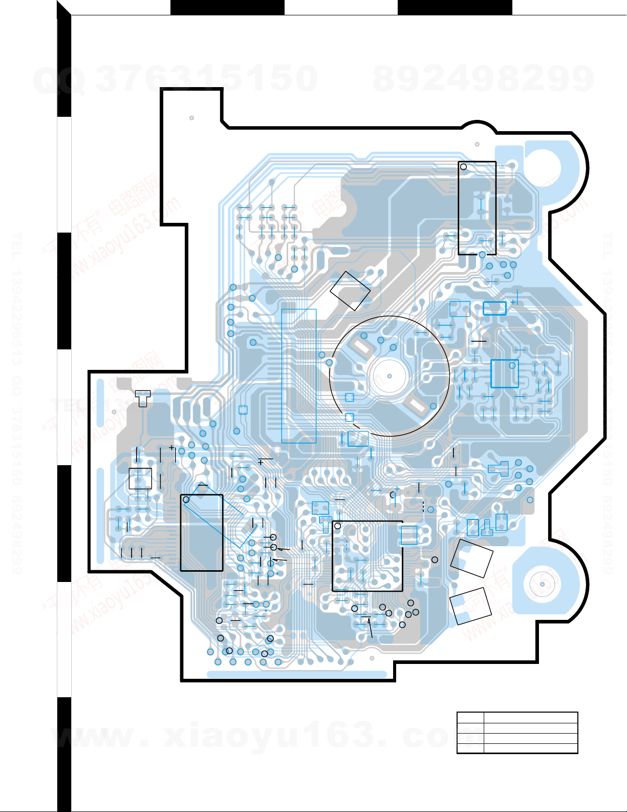
X32-47XX-XX (J74-0992-12)
PC BOARD (COMPONENT SIDE VIEW)
3
7
6
3
1
5
1
5
0
Q
1
Q
2
TEL 13942296513 QQ 376315150 892498299
3
8
9
2
4
9
8
2
9
9
TEL 13942296513 QQ 376315150 892498299
TEL
w
4
5
6
7
w
13942296513
.
xia
w
Refer to the schematic diagram for the values of resistors and capacitors.
o
y
u
Q
Q
1
6
3
7
3
3
6
.
1
5
c
1
5
o
4
2
9
8
0
DC 12456
address
5B 5C 2D 3D 4D
Q 123458
m
address
5A 5D 3D 4C 5D 5C
9
8
2
9
9
F G H I J
1
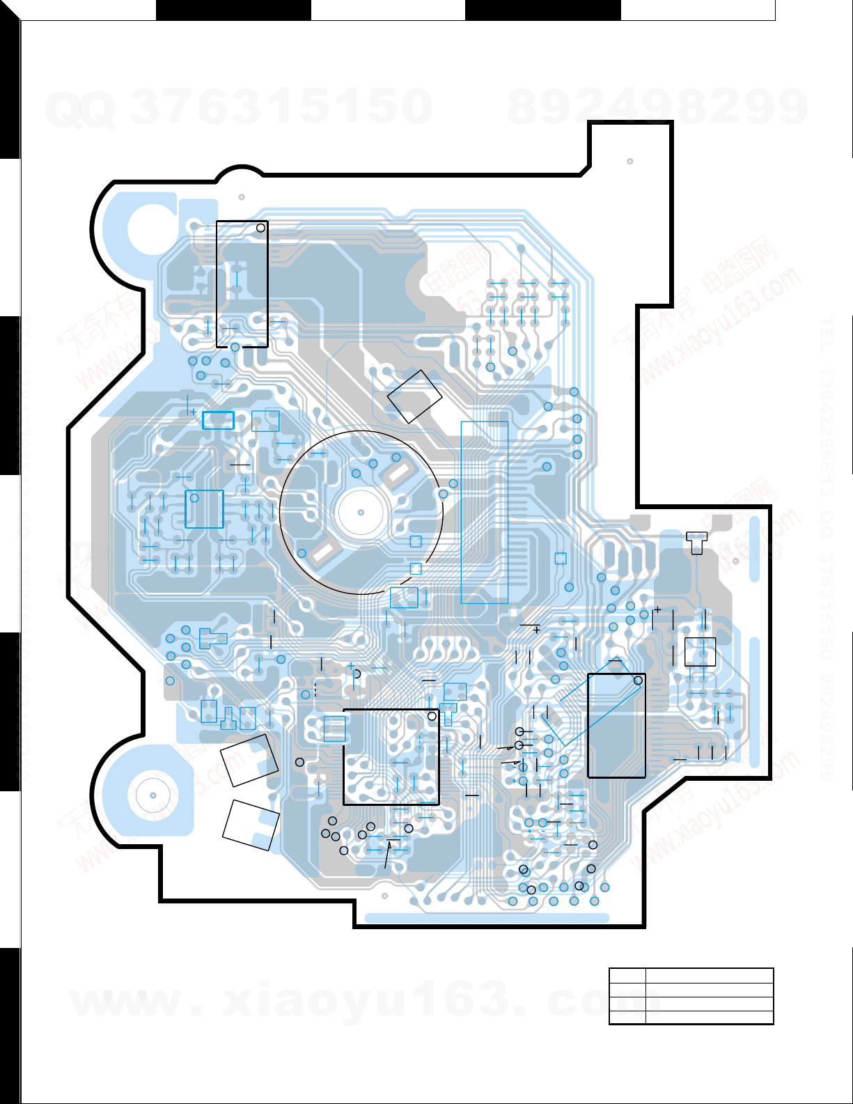
(FOIL SIDE VIEW)
7
Q
Q
3
6
3
1
5
1
5
0
X32-47XX-XX
(J74-0992-12)
IC4
C41
/MUTER
Q3
C79
R125
C77
R121
R31
D2
Q2
BE
1
R76
14
BE
R107
R117
R49
R52
BU.5V
R46
C34
R45
D.OUT
SMCK
R44
SPDL+
W4
X1
DQSY
C22
ST-O
STLD
C46
75
51
FLAG
76
50
/MSTOP
/MRST
C31
CLVS
C21
FCLK
C28
IPFLAG
C25
C29
L2
IC2
C26
S3
Q4
C85
R54
C24
R38
SPDL-
CP2
CP1
Q
E
B
C32
100
R32
TOFS
R37
Q
C55
R219
W8
R34
26
R36
R47
Q8
1
25
A.GND
Lch
3
E
B
C35
R218
2
28
TEL 13942296513 QQ 376315150 892498299
R77
R78
/MUTEL
15
LO/EJ
MOTOR
A.5V
C80
1
4
C72
R104
/RST
SW2
C63
C68
/CLK
OG I
IC6
D3
Q5
IC5
BE
R50
C71
R103
S2
S1
C51
8
5
C67
3
C78
R126
R108
R118
R122
4
5
6
TEL
R102
13942296513
R101
DATA
SW1
D.GND
D4
R35
R75
7
C33
R80
C44
R81
R74
C18
8
R79
TVD
6
R21
TBAL
VDET
LDON
Vref
R72 R83
R71
R73
ECS
EJECT
SLED-
1
CN2
1
3
22
C3
R216
R217
Vc
C19
FBAL
R20
R2
FE
C16
TE
C17
E
BDO
9
C45C43
S.GND
5
CP3
A.+B
F
Vcc
1
R1
R19
R22
R23
R17
C13
C23
/RFDET
TR
RF
Rch
R6
C20
D
R15
F
R82
1
R3
A
R18
R202
TE
ARF
2
LOAD
SLED+
SW3
S.+B
5
TRK+
FCS-
C1
36
CB
19
C15
C2
C14
R16
0
TRK-
VR
16
CN1
TRCRS
OFT
GND
IOP-
4
PD
R5
IC1
IOP+
9
8
FCS+
9
LD
1
18
C4
8
2
R8
R9
C12
D1
9
4
R12
BE
C5
R10
C6 R13
2
8
L1
Q1
R11
C7
C8
C11
C10
9
2
R14
C9
9
9
TEL 13942296513 QQ 376315150 892498299
9
IC 12456
address
w
w
w
7
.
xia
o
y
u
1
6
3
.
c
o
address
5I 5H 2G 3G 4G
Q 123458
m
5J 5G 3G 4H 5G 5H
 Loading...