


KAC-7204
STEREO/BRIDGEABLE POWER AMPLIFIER
~
page 2-5
INSTRUCTION MANUAL
AMPLIFICATEUR DE PUISSANCE STEREO/COMPATIBLE
~
page 6-9
MODE D'EMPLOI
ESTEREO/AMPLIFICADOR DE POTENCIA CONECTABLE
MANUAL DE INSTRUCCIONES
Kenwood Corporation
~
pagina 10-13
@
Take
with
best performance from your
For your records
designated
to the model and serial numbers whenever you call upon your Kenwood
dealer for information or service
© B64-3928-00/00 (KV/EV)
AE86
the
time
to read through this instruction manual. Familiarity
installation and operation procedures will help you obtain
new
power amplifier.
Record the serial number, found on the
on
the warranty card, andinthe space provided below. Refer
Model KAC-7204 Serial number _
US
Residence
Only
on
back
of the unit,inthe spaces
the product.
the
Safety'precautions
AWARNING
To
prevent injuryor fire,
•
When
extending the ignition,
automotive-grade
prevent
•Toprevent ashort circuit,
• If the unit
•Donot touch the unitduring
• Mounting
wire
or
metal
immediately
and
may
sake,
leave
deterioration
tools)
inside
starts
to emit
and
consult your
cause
burns
and
wiring
the mounting
wires
take
battery,
or other
wires
and
damagetothe
never
the
iftouched.
this
put or
unit.
smokeorstrange
Kenwood
use
product
and
wiring work to
the
following precautions:
or ground
because
requires
wires,
with a8 mm'
wire
leave
any
metallic objects
smells,
turn offthe power
dealer.
the
surfaceofthe unit
skills
and
professionals.
coating.
ACAUTION
To
prevent damagetothe
machine, take
the
precautions:
•Besure
the
ground connection.
•Donot open the bottom
Do
•
or humidity.
splashing.
•
When
fuse
•
To
harness.
unitisconnected to a
not
install
the unitinaspot
Also
avoid
replacingafuse,
with
the
wrong
prevent a short circuit when
rating
places
only
12V
coversofthe
exposed
with too
useanew
may
cause
replacingafuse,
DC
power supply with a negative
unit.
to direct sunlightorexcessive
much
dust or the possibility of
one
with
the
your unit to malfunction.
first
NOTE
• If
you
experience
• If the unit
problems during installation, consult your
does
not
seemtobe
working right, consult your
Wiring
•
Take
the
battery wire
vehicle's
the
• If a
buzzing
connect a line
•Donot allow the wire to directly contact the edgeofthe
Grommets.
• Connect the ground
electrical
ground
not turn
the
Be
suretoinstall
•
protective
somewhat
•
For
cord
wiring
•
When
supply wiring
than
fuse
the power cord
with a current
cord
more
the total maximum current drawnbyeach
for
this
wiring
noiseisheard
noise
passing
poweronif
aprotective
shouldbethe
larger.
with a diameter of 8 mm'
than
one
wire
unit directly
harness,itcan
from
filter (optional) to
wire
and
capacity
and
the
to a
metal
electricitytothe
the
ground
fuseinthe
same
ground,
greater
power amplifier
protective
useavehicle
from
the
cause
blown
speakers
each
part of the
wireisnot connected.
power
capacityasthe
than
(AWG8)or
are
fuseofgreater
battery.Ifit's
fuses
when the engineisrunning,
ofthe battery
car
chassis
battery's negative e
cord
unit's
type (fireproof) power wring
the
unit's
fuse
greater.)
going tobeused,
current-handling
amplifier.
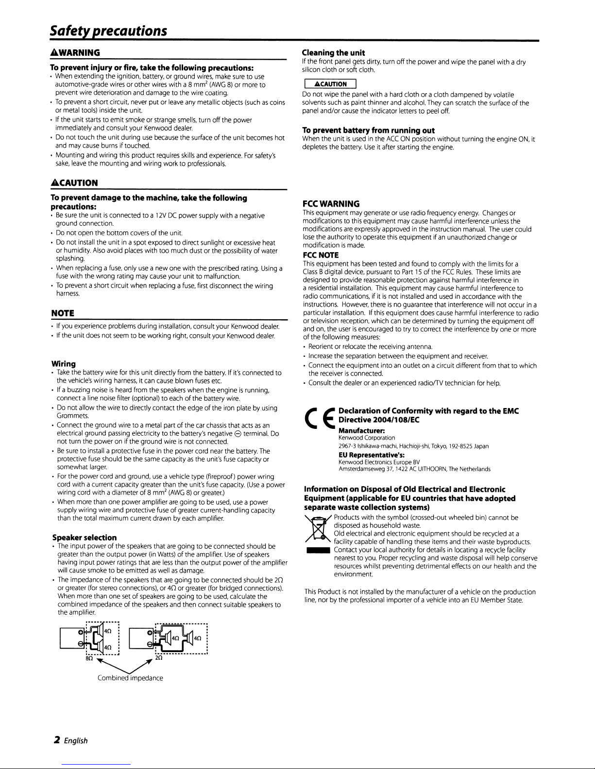
Speaker selection
•
The
input power of the
greater than
having input power
will
•
The
or
greater
When
combined impedance
the
the
cause
smoketobe
impedance of the
(for
more
than
amplifier.
speakers
output power
ratings
that
emittedaswellasdamage.
speakers
stereo
connections), or40or
one
setofspeakers
of
the
speakers
(in
that
are
that
Watts)
less
are
are
of the
than
goingtobe
are
going tobeused,
and
going tobeconnected
amplifier.
the
output power of
greater
then connect
: .
o'
40:~'
: ; :
•
~
:
__
40.
~
40
•
ko···--·
40
· ·
80~
Combined impedance
make
suretouse
(AWG8)or
experience.
more
to
(suchascoins
becomes
For
safety's
following
heat
water
prescribed
disconnect
etc.
near
connected shouldbe20
(for
rating.
Using
the
wiring
Kenwood
Kenwood
wire.
iron
that
the
fuse
capacity.
Useofspeakers
bridged connections).
calculate
suitable
dealer.
dealer.
connected to
platebyusing
actsasan
terminal.
battery.
The
capacity
(Use
apower
use
apower
capacity
should
the
the
speakers
Do
or
be
amplifier
Cleaning
If the front
silicon
I
Do
solvents
panel
To
hot
When
depletes the
FCC
This
modifications to
modifications
lose
modificationismade.
FCC
This
a
Class
designed
a
radio
instructions.
particular installation. If
or television reception, which
and
of
•
•
• Connect the equipmentintoanoutletonacircuit different
• Consult the
(
the
unit
panel
gets
soft
the
cause
dirty, turn off
cloth.
I
panel
the
with a
indicator
hard
cloth or a clothdampenedbyvolatile
and
alcohol.
letterstopeel
cloth or
"CAUTION
not wipe
suchaspaint thinner
and/or
prevent batteryfrom running
the unitisusedinthe
battery.
ACCONposition without turning
Useitafter
starting the
WARNING
equipment
the authorityto operate
NOTE
equipment
Bdigital
residential
communications, if itisnot
on,
the following
Reorientorrelocate
Increase
the
receiverisconnected.
may
generateoruse
thiS
equipment
are
expressly
has
been
device,
to provide
the
the
t:
~
pursuanttoPart15of
reasonable
installation.
However,
userisencouraged
measures:
the
separation
dealeroran
DeclarationofConformity with regardtothe
Directive
Manufacturer:
Kenwood Corporation
2967-3Ishikawa-machi, Hachioji-shi,
EU
Representative's:
Kenwood
Electronics
Amsterdamseweg 37,1422ACUITHOORN,
may
approvedinthe instruction
this
equipment ifanunauthorized
tested
and
protection
This
equipment
thereisno
installed
guarantee that interference will not occurina
this
equipment
canbedeterminedbyturning the equipment off
to try to correct
receiving
between the equipment
experienced
2004/1
08/EC
Europe
the
radio
cause
found
antenna.
8V
Information on DisposalofOld Electrical and Electronic
Equipment (applicableforEUcountries
separate wastecollection systems)
Products
with
the
symbol
disposedashousehold
Old
electrical
)t
This
to
line,
facility
_ Contact your
nearesttoyou.
resources
environment.
Productisnot
norbythe
and
capable
of handling
local
Proper
whilst preventing detrimental
installedbythe manufacturerofavehicleonthe production
professional
(crossed-out
waste.
electroniC
authority
recycling
importerofavehicle intoanEU
power
and
wipe the
They
can
scratch
off.
out
engine.
frequency
may
and
does
radiolTV technician
energy.
harmful interference
to comply with
the
FCC
Rules.
against
harmful interference
cause
harmful interference to
usedinaccordance
cause
harmful interference to
the
interferencebyoneormore
and
Tokyo,
192-8525
The
that
wheeled
equipment
these
for
shouldberecycledata
items
and
detailsinlocating a
and
waste
effects
panel
with adry
the
surfaceofthe
the
engine
Changes
unless
manual.
The
change
the
limits
These
limits
receiver.
from
for
help.
Japan
Netherlands
have adopted
bin)
cannot
their
waste
recycle
disposal
will help
on our health
Member
ON,
or
the
user
could
or
for
a
are
in
with the
radio
that to which
EMC
be
byproducts.
facility
conserve
and
State.
it
the
2
English
Installation
350mm
~
312mm
~~
~
~
~
KENWOOD
325.5mrn
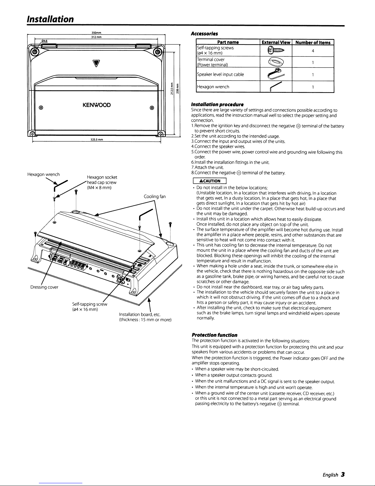
head cap screw
(M4x8mm)
@
Hexagon wrench Hexagon socket
r
V(
I Cooling
~~
~
@
Installation board, etc.
(thickness:
\
15mmor more)
fan
Accessories
Part
Self-tapping screws
name
(04x16mm)
Terminal cover
Power terminal)
input
Speaker level
E
E
:;s
Hexagon wrench
Instllllationprocedure
Since
there
applications,
connection.
1.Remove the ignition key and disconnect the negative
to
2.Set
3.Connect the
4.Connect the speaker wires.
5.Connect the power wire, power control wire and grounding wire following this
order.
6.lnstall the installation fittings in
7.Attach the unit.
8.Connect the negative
• Do
• Do
• Install thiS
• The surface temperature
• This
• When making a hole under a seat, inside
• Do
• The installation
• Aher installing
are
prevent short circuits.
the unit accordingtothe intended usage.
.6.CAUTION
not
install in
(Unstable location,
that gets wet,
gets
direct
not
install
the
unit
may be damaged.
Once installed,
the
amplifier in a place where people, resins, and
sensitive
to
unit
has
mount
the
blocked. Blocking these openings will
temperature and result in malfunction.
the
vehicle, check that thereisnothing
as
a gasoline tank, brake pipe, or wiring harness, and be careful
scratches or other damage.
not
install near
which it will
hits a person or safety part, it may cause injury or an accident.
suchasthe
normally.
cable
large varietyofsettings and connections possible according
read
the instruction manual welltoselect the proper setting and
input
and
output
8 terminal
the
below
In
a location that interferes
Inadusty
sunlight,Ina location
the
unit
under the
unit
in a location which allows heattoeasily dissipate.
do
not
place any
heat will
not
cooling fantodecrease the internal temperature. Do
unit
in a place where
the
dashboard, rear tray, or air bag safety parts.
to
the vehicle should securely fasten
not
obstruct driving. If
the
unit, checktomake sure
brake lamps, turn signal lamps and windshield wipers operate
External
View
NumberofItems
@Imn-
~
~
r
8 terminal
wiresofthe units.
the
unit.
of
the battery.
locations;
location, In a place that gets hot,Ina place
that
carpet. Otherwise heat bUild-up occurs and
objectontopofthe unit.
of
the
amplifier will
come
into
contact
the
cooling fan and ductsofthe
the
with
driving, In a location
gets
hitbyhot
inhibit
the
hazardous on
unit
air)
become
hot
other
with
the
trunk,orsomewhere else in
comes
that
substances
it.
coolingofthe
the
the
off
duetoa shock and
electrical
4
1
1
1
to
of
the battery
that
during
use.
Install
that
are
not
unit
are
internal
opposite side such
nottocause
unittoa place in
equipment
Protection function
The protection functionisactivated in the following situations:
This
unitisequipped with a protection function for protecting this
speakers from various accidents or problems that
When the protection function
amplifier stops operating.
• When a speaker wire may
• When a speaker
• When the unit malfunctions and a
• When the internal temperature
• When a ground wire
or this unit
passing electricity
output
is
not connectedtoa metal part servingasan electrical ground
to
is
triggered, the Power indicator goes
be short-circuited.
contacts ground.
DC
is
of
the center
the battery's negative 8 terminal.
high and unit won't operate.
unit
can
occur.
signalissenttothe speaker output,
(cassette receiver,CDreceiver, etc.)
unit
OFF
English
and your
and the
3
Connection
I AWARNING I
To
prevent
fire
connect a fusible link or
battery's positive terminal.
ACAUTION
• If soundisnot output normally, immediately turn
power off
Be
sure
•
setting of
• If the
replace
Check
•
are
caps
prevent short circuits.
• Connect the
connectors
ofthe
metal body of the
NOTE
•Donot connect
cable input
terminals simultaneously, for this
malfunction or
causedbyashortinthe wiring,
and
to turn the power off before changing the
any
fuse
blows, check
the
fuse
that no unconnected
touching the
from unconnected
separately.
speaker
jacks
Speakerlevel
•
The
genuine-accessory
maximum power output of
•
The
poweristurnedonand
detects input
There
foreitis
power control
breaker
check
connections.
switch.
wires
with oneofthe
car
speaker
or grounding
car
cables
and
damage.
Input
signal
not
wire.
wiresorconnectors
body.Donot remove
wiresorconnectors to
wires
to appropriate
Sharing
speaker
can
cause
and
leads
the
speaker
connections
car
stereo
no
offasthe unit
(Signal
Sensing
necessarytoconnect the
nearby the
for
shorts,
then
same
rating.
wires
this unit to
to both
level
input
may
cause
shall
have
Turn-ON)
speaker
RCA
40
the negative wire
more than
to the
fail.
•
•
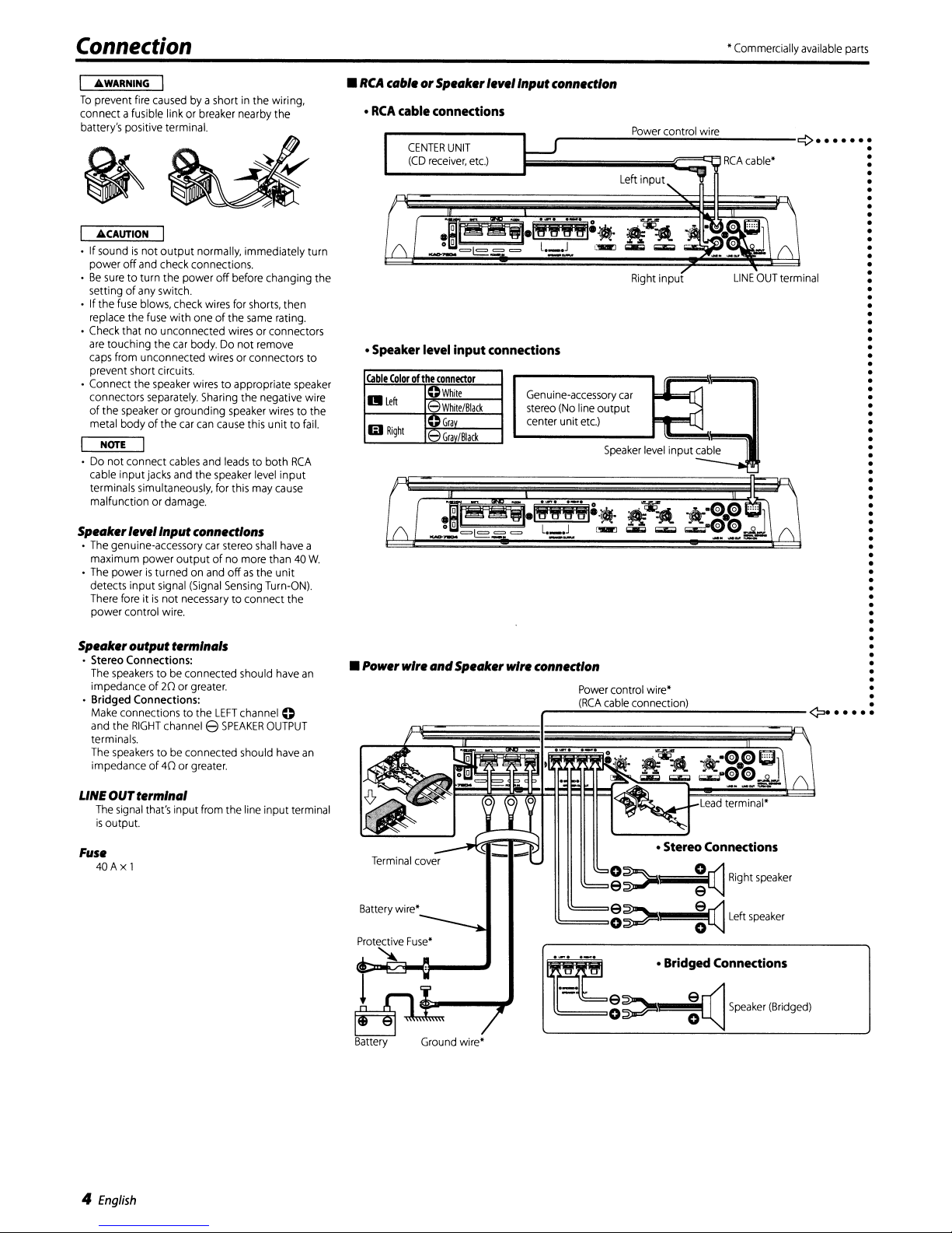
RCA
cable or Speakerlevel
•
RCA
cable
CENTER
(CD
connections
UNIT
receiver,
etc.)
Input
I-J
connectIon
P
ower contro
Left
input,
"""l
wire
Commercially
RCA
cable'
available
parts
¢ .
o
o
o
o
! '\
(\
•
Speaker
Colorofthe
Cable
left
I!I
RighI
.~II
~
-:::=e
level input
conne<tor
;:
While
While/Black
;:
Grav
-
Grav/Black
0
~
"1
1";"";'-"1-"
= =
l._J
connections
Genuine-accessory
stereo
center unit
(No
line output
etc.)
CIIIIrJ
Speaker
-=
~
Right
car
W~
~
~
level
~to~r:J1
"(j
...
W_.
_..:w:
input
input
/
cable
LINE
OUT
f\
\
terminal
J
(
e
0~1I~
-:::=t=:~
a
W.
(\
~
=
..
e::t
I''-'n1,-wl
l..J
1iiW~
.•
~
~
.oe.etJ
=
......
~~~-
1
f\
o
Speakeroutput terminals
• Stereo Connections:
The
speakerstobe
impedance of20or
• Bridged Connections:
Make
connections to the
and
the
RIGHT
terminals.
The
speakerstobe
impedance of40or
LINE
OUT
terminal
The
signal
is
output.
channel e
that's
input
connected should
greater.
connected should
greater.
from
Fuse
40Ax
1
have
LEFT
channel 0
SPEAKER
OUTPUT
have
the line input terminal
•
Power
an
an
wIreandSpeaker
wire
connection
Power
control wire'
(RCA
cable
r--.....:;,;.:;;.,;.:;;.:,;.::..:.:;;.;;.==;:....--------~
\!===~~~
~
~:~
connection)
~~~
0
Bridged
Right
speaker
Left
speaker
Connections
SO',""
",""'"
0 0 0 0
4
English