

Page 1

DIGITAL SURROUND AMPLIFIER
KAF-S500
INSTRUCTION MANUAL
KENWOOD CORPORATION
About the supplied remote control
Compared to standard remote controls, the remote control supplied with this amplifier has several
operation modes. These modes enable the remote control to control other audio/video components. In
order to effectively use the remote control, it is important to read the operating instructions and obtain
a proper understanding of the remote control and how to switch its operation modes (etc.).
Using the remote control without completely understanding its design and how to switch the operation
modes may result in incorrect operations.
B60-5392-08 00 CH (Y) KW 0304
Page 2
Before applying the power
l
-
.
Caution : Read this page carefully to ensure safe
operation.
Units are designed for operation as follows.
U.S.-Military .................................................... AC 110 - 240 V
How to use this manual
This manual is divided into four sections, Preparations, Operations,
Remote Control, and Additional Information.
Preparations
Shows you how to connect your audio and video components to the
receiver and prepare the surround processor.
Since this receiver works with all your audio and video components,
kindly follow the instructions in this manual for the correct connections.
Operations
Shows you how to operate the various functions available on the
receiver.
Remote Control
Shows you how to operate other components using the remote control,
as well as a detailed explanation of all remote control operations. Once
you have registered your components with the proper setup codes, you’ll
be able to operate both this receiver and your other AV components (TV,
VCR, DVD player, CD player, etc.) using the remote control supplied with
this receiver.
Additional Information
Shows you additional information such as “In case of difficulty”
(troubleshooting) and “Specifications”.
Unpacking
Unpack the unit carefully and make sure that all accessories are
present.
Remote control unit (1) Batteries (R03/AAA) (2)
If any accessories are missing, or if the unit is damaged or fails to operate,
notify your dealer immediately. If the unit was shipped to you directly,
notify your shipper immediately. Kenwood recommends that you retain
the original carton and packing materials in case you need to move or ship
the unit in the future.
Keep this manual handy for future reference.
Maintenance of the unit
When the front panel or case becomes dirty, wipe with a soft, dry
cloth. Do not use thinner, benzine, alcohol, etc. for these agents may
cause discoloration.
In regard to contact cleaner
Do not use contact cleaners because it could cause a malfunction. Be
specially careful not to use contact cleaners containing oil, for they
may deform the plastic component.
For the U.S.A.
FCC WARNING
This equipment may generate or use radio frequency energy. Changes
or modifications to this equipment may cause harmful interference
unless the modifications are expressly approved in the instruction
manual. The user could lose the authority to operate this equipment
if an unauthorized change or modification is made.
NOTE:
This equipment has been tested and found to comply with the limits for
a Class B digital device, pursuant to Part 15 of the FCC Rules. These
limits are designed to provide reasonable protection against harmfu
interference in a residential installation. This equipment may cause
harmful interference to radio communications, if it is not installed and
used in accordance with the instructions. However, there is no guaran
tee that interference will not occur in a particular installation. If this
equipment does cause harmful interference to radio or television
reception, which can be determined by turning the equipment off and
on, the user is encouraged to try to correct the interference by one or
more of the following measures:
– – Reorient or relocate the receiving antenna.
– – Increase the separation between the equipment and receiver.
– – Connect the equipment into an outlet on a circuit different from
that to which the receiver is connected.
– – Consult the dealer or an experienced radio / TV technician for help
EN
2
Safety precautions
WARNING :
TO PREVENT FIRE OR ELECTRIC SHOCK,
DO NOT EXPOSE THIS APPLIANCE TO
RAIN OR MOISTURE.
CAUTION
RISK OF ELECTRIC SHOCK
DO NOT OPEN
CAUTION: TO REDUCE THE RISK OF ELECTRIC SHOCK, DO NOT
REMOVE COVER (OR BACK). NO USER-SERVICEABLE PARTS
INSIDE. REFER SERVICING TO QUALIFIED SERVICE PERSONNEL.
THE LIGHTNING FLASH WITH ARROWHEAD SYMBOL,
WITHIN AN EQUILATERAL TRIANGLE, IS INTENDED TO
ALERT THE USER TO THE PRESENCE OF UNINSULATED
“DANGEROUS VOLTAGE” WITHIN THE PRODUCT’S
ENCLOSURE THAT MAY BE OF SUFFICIENT MAGNITUDE
TO CONSTITUTE A RISK OF ELECTRIC SHOCK TO
PERSONS.
THE EXCLAMATION POINT WITHIN AN EQUILATERAL
TRIANGLE IS INTENDED TO ALERT THE USER TO THE
PRESENCE OF IMPORTANT OPERATING AND
MAINTENANCE (SERVICING) INSTRUCTIONS IN THE
LITERATURE ACCOMPANYING THE APPLIANCE.
Page 3

Before applying the power
Special features
True home theater sound
This amplifier incorporates a wide variety of surround modes to bring you
maximum enjoyment from your video software. Select a surround mode
according to your equipment or the software you are going to play and
enjoy! ¡
Dolby Digital and Dolby Digital EX
The DOLBY DIGITAL mode lets you enjoy full digital surround from
software processed in the Dolby Digital format. Dolby Digital provides
up to 5.1 channels of independent digital audio for better sound quality
and more powerful presence than conventional Dolby Surround.
As for Dolby Digital EX, it creates six full-bandwidth output channels
from the 5.1 channel sources. This is done using a matrix decoder that
derives three surround channels from the two in the original recording.
For best results, Dolby Digital EX should be used with movie soundtracks
recorded with Dolby Digital Surround EX.
Dolby PRO LOGIC II
Dolby PRO LOGIC II , whilst totally compatible with its predecessor
PRO LOGIC, provides greater advantages in surround sound. It allows
the user to enjoy the conventional stereo or Dolby Surround with a
convincing “5.1 like” presentation. PRO LOGIC II offers special features
for controlling the overall spatial, dimensionality and frontal sound field
imaging. PRO LOGIC II produces an impressive surround sound from
video software marked
from music CD. When listening to music, you will be able to enjoy the
experience of sheer STEREO surround sound.
and three-dimensional space
DTS and DTS-ES
DTS (Digital Theater System) is a 5.1 channel digital audio format that
provides five full spectrum channels and one low-frequency (subwoofer)
channel for unprecedented clarity, optimum channel separation and a
(wide) dynamic range.
DTS-ES (Extended Surround) presents 6.1 channels surround system
with additional Back Surround channel which evolved from the
conventional 5.1 channels surround system. DTS-ES format that was
recorded in DVD, CD or LD comprises of two modes. DTS-ES Discrete
6.1 produce the discrete back surround which is completely independent
and DTS-ES Matrix 6.1 produces the back surround which synthesized
within the left and right surround channels using matrix technology.
DTS-ES has perfect compatibility with the conventional 5.1 channels
surround system. 6.1 channels surround with an additional surround
back presents a more natural presence and surround effects by
increasing the impression of the sound image from back.
Important:
When a DTS disc is played on a CD, LD or DVD player, noise may be
output from the analog output. It is recommended that you connect the
digital output of the player to the digital input of this unit.
DSP surround modes
The DSP (Digital Signal Processor) used for this receiver incorporates
a variety of high quality adjustable sound fields, like “ARENA”, “JAZZ
CLUB”, “STADIUM” , “DISCO”and “THEATER”. It is compatible with
almost any kind of program source.
ACTIVE EQ
ACTIVE EQ mode will produce a more dynamic sound quality in any
condition. You can enjoy a more impressive sound effect when ACTIVE
EQ is turned on during Dolby Digital and DTS playback.
Universal IR (InfraRed) remote control
In addition to the basic receiver, the remote control supplied with this
receiver can also operate almost all of your remote controllable audio
and video components. Just follow the simple setup procedure to
register the components you have connected.
Neo:6
Neo:6 is a new technology which was developed by DTS. It can produce
high grade 6 channels surround with an astonishing fidelity from 2
channels content. Neo:6 has 2 mode, "CINEMA" mode is for movie
playback and "MUSIC" mode is for music playback.
SRS TruSurround
There are only two speakers but you will be searching for others. SRS
TruSurround can take in any mono, stereo, or multiple channel source,
such as Dolby Digital and immerse you into a field sound you would
have thought impossible through two speakers.
EN
3
Page 4

Before applying the power
Contents
Caution : Read the pages marked carefully to ensure
safe operation.
Before applying the power ..............................2
How to use this manual..................................... 2
Unpacking ..........................................................2
Safety precautions ............................................. 2
Special features .................................................3
IMPORTANT SAFEGUARDS ............................. 5
Names and functions of parts ......................... 7
Main unit ............................................................ 7
Remote control unit ........................................... 8
Preparations
Setting up the system........................................ 9
Connecting audio components........................ 10
Connecting the speakers
(for HTB-S500 system) ....................................11
Connecting the speakers (for KAF-S500) ....... 12
Connecting the terminals ................................ 13
Connecting to the FRONT AUX jacks.............. 14
Preparing the remote control .......................... 14
Preparing for surround sound .......................15
Speaker settings .............................................. 15
Normal playback.............................................. 18
Preparing for playback .....................................18
Listening to a source component.................... 18
Adjusting the sound......................................... 19
Recording ..........................................................20
Recording audio (analog sources) ................... 20
Ambience effects............................................. 21
Operations
Surround modes ..............................................21
Surround play ................................................... 23
SRS TruSurround play...................................... 24
Convenient functions ......................................25
Adjutment of each channel’s level .................. 25
Midnight mode (Dolby Digital mode only)....... 25
Display dimmer adjutment .............................. 25
Sleep timer (SLEEP)......................................... 25
96kHz LPCM playback ..................................... 25
Remote
Control
Additional
Information
EN
4
Basic remote control operations for other
components....................................................... 26
Registering setup codes for other components
.........................................................................26
Operating other components ..........................27
Setup code chart.............................................. 28
Other components’ operations ....................... 32
In case of difficulty.......................................... 34
Specifications .................................................. 35
Page 5
IMPORTANT SAFEGUARDS
Caution : Read this page carefully to ensure safe
operation.
Please read all of the safety and operating instructions before
operating this appliance. Adhere to all warnings on the appliance
and in the instruction manual. Follow all the safety and operating
instructions. These safety and operating instructions should be
retained for future reference.
1. Power sources – The appliance should be connected to a
power supply only of the type described in the instruction
manual or as marked on the appliance. If you are not sure of
the type of power supply to your home, consult your appliance
dealer or local power company. For appliances intended to
operate from battery power, or other sources, refer to the
instruction manual.
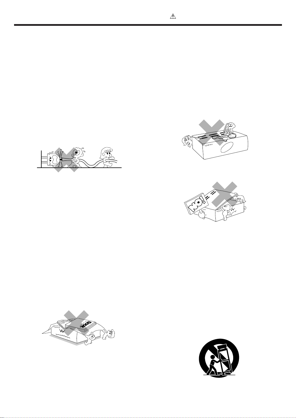
2. Power-cord protection – Power-supply cords should be
routed so that they are not likely to be walked on or pinched by
items placed upon or against them, pay particular attention to
cords at plugs, convenience receptacles, and the point where
they exit from the appliance.
Never pull or stretch
the cord.
3.
CAUTION – Polarization – This appliance may be
equipped with a polarized alternating-current line plug (a plug
having one blade wider than the other). This plug will fit into the
power outlet only one way. This is a safety feature. If you are
unable to insert the plug fully into the outlet, try reversing the
plug. If the plug should still fail to fit, contact your electrician to
replace your obsolete outlet. Do not defeat the safety purpose
of the polarized plug.
6. Temperature – The appliance may not function properly if
used at extremely low, or freezing temperatures. The ideal
ambient temperature is above +5°C (41°F).
7. Heat – The appliance should be situated away from heat
sources such as radiators, heat registers, stoves, or other
appliances (including amplifiers) that produce heat. Do not
place a flaming object, such as a candle or lantern, on or near
the appliance.
8. Electric shock – Care should be taken so that objects do not
fall and liquid is not spilled into the enclosure through openings.
If a metal objects, such as a hair pin or a needle, comes into
contact with the inside of this appliance, a dangerous electric
shock may result. For families with children, never permit
children to put anything, especially metal, inside this appliance.
9. Enclosure removal – Never remove the enclosure. If the
internal parts are touched accidentally, a serious electric shock
might occur.
4. Ventilation – Slots and openings in the cabinet are provided
for ventilation and to ensure reliable operation of the appliance
and to protect it from overheating, and these openings must
not be blocked or covered. The appliance should be situated so
that its location or position does not interfere with its proper
ventilation.
To maintain good ventilation, do not put records or a table-cloth
on the appliance. Place the appliance at least 10 cm away from
the walls.
Do not use the appliance on a bed, sofa, rug or similar surface
that may block the ventilation openings. This appliance should
not be placed in a built-in installation such as a bookcase or rack
unless proper ventilation is provided or the manufacturer’s
instructions have been adhered to.
5. Water and moisture – The appliance shall not be exposed to
dripping and splashing - for example, near a bathtub, washbowl,
kitchen sink, laundry tub, in a wet basement, or near a
swimming pool, etc. Do not place an object containing liquid,
such as a flower vase, on the appliance.
10.Magnetic fields – Keep the appliance away from sources of
magnetic fields such as TV sets, speaker systems, radios,
motorized toys or magnetized objects.
11.Cleaning – Unplug this appliance from the wall outlet before
cleaning. Do not use volatile solvents such as alcohol, paint
thinner, gasoline, or benzine, etc. to clean the cabinet. Use a
clean dry cloth.
12.Accessories – Do not place this appliance on an unstable cart,
stand, tripod, bracket, or table. The appliance may fall, causing
serious injury to a child or adult, and serious damage to the
appliance. Use only with a cart, stand, tripod, bracket, or table
recommended by the manufacturer, or sold with the appliance.
Any mounting of the appliance should follow the manufacturer’s
instructions, and should use a mounting accessory
recommended by the manufacturer. An appliance and cart
combination should be moved with care. Quick stops, excessive
force, and uneven surfaces may cause the appliance and cart
combination to overturn.
EN
5
Page 6
IMPORTANT SAFEGUARDS
Caution : Read this page carefully to ensure safe
operation.
13.Lightning – For added protection for this appliance during a
lightning storm, or when it is left unattended and unused for
long periods of time, unplug it from the wall outlet and
disconnect the antenna or cable system. This will prevent
damage to the appliance due to lightning and power-line
surges.
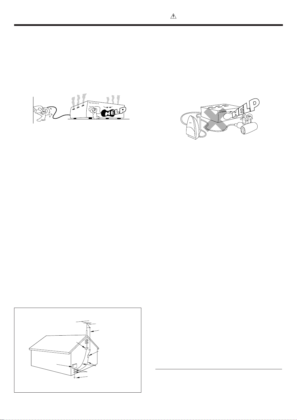
14.Abnormal smell – If an abnormal smell or smoke is
detected, immediately turn the power OFF and unplug
the appliance from the wall outlet. Contact your dealer or
nearest service center.
15.Damage requiring service – The appliance should be
serviced by qualified service personnel when:
A. The power-supply cord or the plug has been damaged.
B. Objects have fallen, or liquid has been spilled into
the appliance.
C. The appliance has been exposed to rain or water.
D. The appliance does not appear to operate normally
by following the instruction manual. Adjust only those controls
that are covered by the instruction manual as an improper
adjustment of other controls may result in damage and will
often require extensive work by a qualified technician to
restore the appliance to its normal operation.
E. The appliance has been dropped, or the enclosure
damaged.
F. The appliance exhibits a marked change in performance.
18.Power lines – An outside antenna system should not be
located in the vicinity of overhead power lines or other electric
light or power circuits, or where it can fall into such power lines
or circuits. When installing an outside antenna system, extreme
care should be taken to keep from touching such power lines
or circuits as contact with them might be fatal.
19.AC outlets – Do not connect other audio equipment
with a power consumption larger than that specified to
the AC outlet on the rear panel. Never connect other
electrical appliances, such as an iron or toaster, to it to
prevent fire or electric shock.
20.Overloading – Do not overload wall outlets, extension cords,
or integral convenience receptacles as this can result in a risk
of fire or electric shock.
21.Attachment – Do not use attachments not recommended by
the appliance manufacturer as they may cause hazards.
22.Replacement parts – When replacement parts are required,
be sure the service technician has used replacement parts
specified by the manufacturer or have the same characteristics
as the original parts. Unauthorized substitutions may result in
fire, electric shock, or other hazards.
16.Servicing – The user should not attempt to service the
appliance beyond that described in the instruction
manual. All other servicing should be referred to qualified
service personnel.
17.Outdoor antenna grounding – If an outside antenna is
connected to the appliance, be sure the antenna system
is grounded so as to provide some protection against
voltage surges and built up static charges. Article 810 of
the National Electrical Code ANSI/NFPA 70, provides
information with respect to proper grounding of the
mast and supporting structure, grounding of the lead-in
wire to an antenna discharge unit, size of grounding
conductors, location of antenna discharge unit,
connection to grounding electrodes, and requirements
for the grounding electrode. See Figure.
EXAMPLE OF ANTENNA GROUNDING AS PER NATIONAL
ELECTRIC
SERVICE
EQUIPMENT
NEC – NATIONAL ELECTRICAL CODE
ELECTRICAL CODE
GROUND
CLAMPS
ANTENNA
LEAD IN WIRE
ANTENNA
DISCHARGE UNIT
(NEC SECTION 810-20)
GROUNDING CONDUCTORS
(NEC SECTION 810-21)
GROUND CLAMP
POWER SERVICE GROUNDING
ELECTRODE SYSTEM
(NEC ART 250, PART H)
23.Safety check – Upon completion of any service or repairs to
this appliance, ask the service technician to perform safety
checks to determine that the appliance is in proper operating
condition.
Notes:
1. Item 3 is not required except for grounded or polarized equipment.
2. Item 17 and 18 are not required except for units provided with antenna
terminals.
3. Item 17 complies with UL in the U.S.A.
EN
6
Page 7
Names and functions of parts
E
C
S
O
S
Y
DIGITAL SURROUND AMPLIFIER KAF-S500
R
N
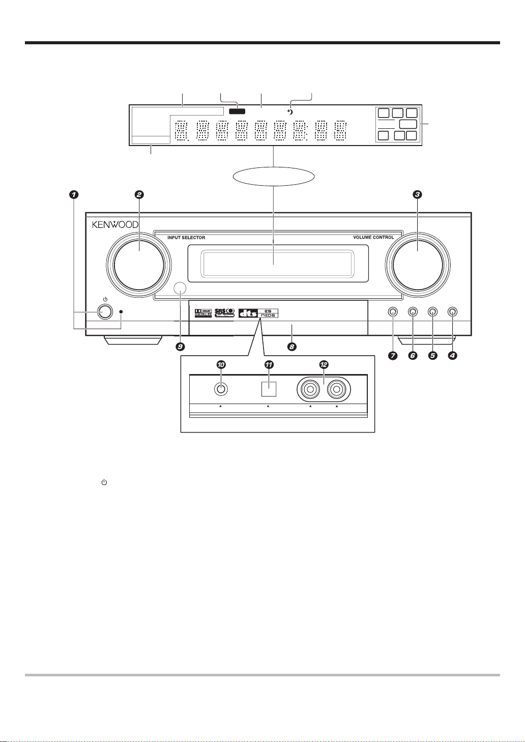
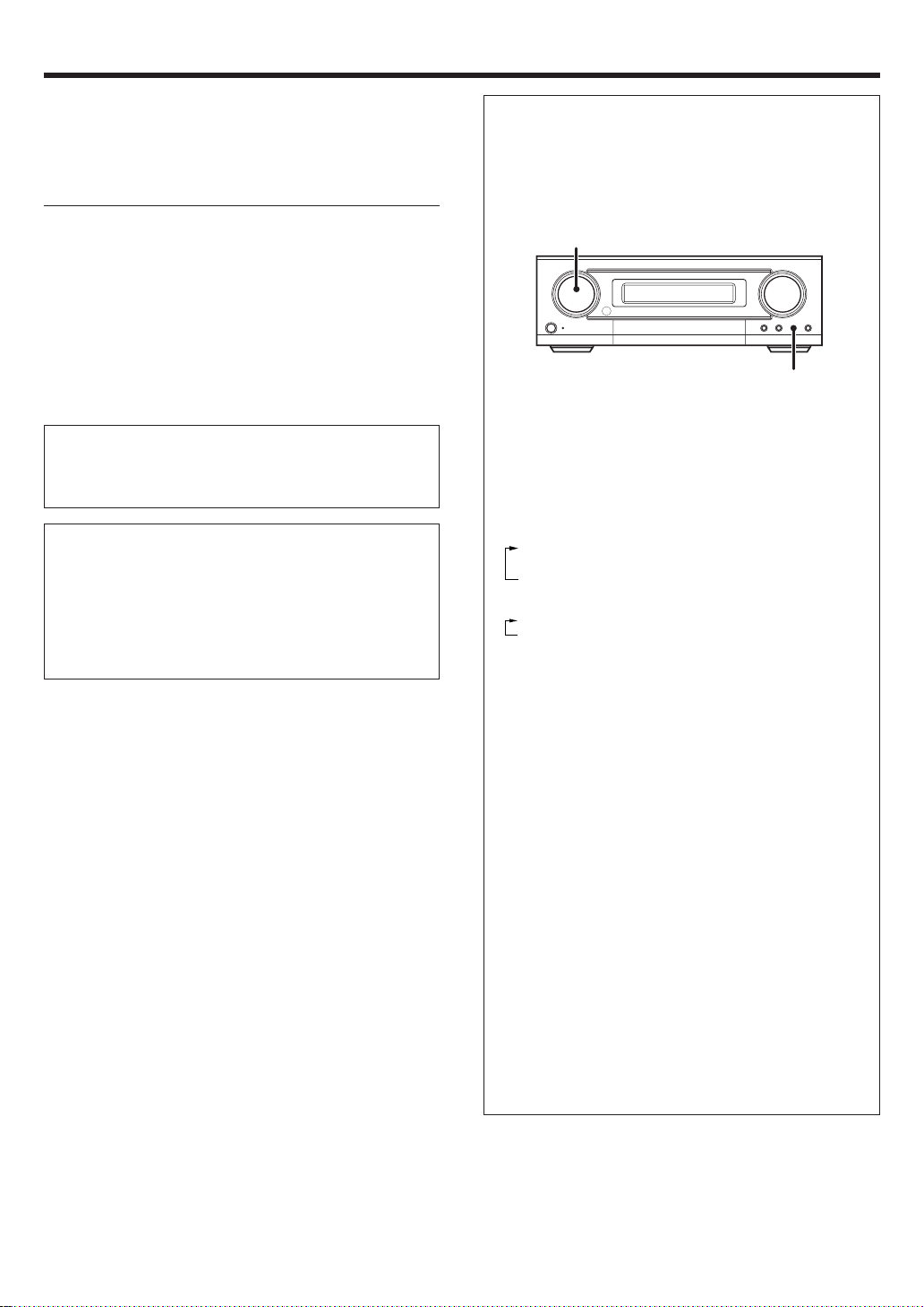
Main unit
Listen Mode
indicators
DOLBY PLII
DTS -ES AAC
DISCRETE
MATRIX 6.1
ACTIVE EQ.
ACTIVE EQ.
indicator
TAND B
MUTE
indicator
DIGITAL
indicator
MUTEDOLBY DEX NEO:6 DSP TS DIGITAL RDS PTY ST. TUNED
Sleep
indicator
Display
AV CONTROL CENTE
AUTO
FM/AM
kHz
MHz
PUSH OPE
L
CR
LFE SW
LS S BS RS
TERE
LISTEN MOD
Speaker selection
indicators
A
TIVE EQ.
INPUT MODE
PHONES AUX OPTICAL L -AUDIO -R
Inside of FRONT AUX jacks' door
1 (POWER) key %
Use to turn the main power on or off.
STANDBY indicator
Lights when stand by mode.
2 INPUT SELECTOR knob *
(DVD/CD, VIDEO 1, VIDEO 2, FRONT AUX)
Use to select input sources.
3 VOLUME CONTROL knob *
4 ACTIVE EQ key (
Use to select ACTIVE EQ’s setting.
5 INPUT MODE key 9
Use to switch between the full auto, digital
and analog inputs.
7 STEREO key £
Use to switch the listen mode to STEREO.
8 Door for FRONT AUX jacks $(
When you use FRONT AUX jacks, push right
side of this door and then pull the door to
open.
9 Remote sensor $
0 PHONES jack (
Use for headphone listening.
! FRONT AUX (Digital in) jack
@ FRONT AUX (L-AUDIO-R) jacks $
6 LISTEN MODE key £
Use to select the listening mode.
Standby mode
While the standby indicator is lit, a small amount of power is supplied to the system to back up the memory. This is called standby mode. Under the condition,
the system can be turned ON by remote control unit.
EN
7
Page 8
Names and functions of parts
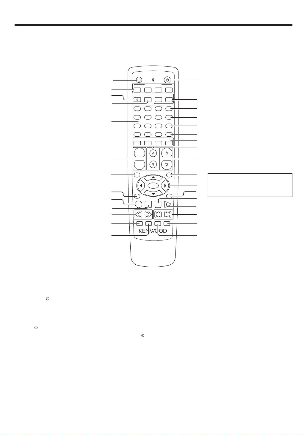
Remote control unit
This remote control unit can be used not only for Kenwood products but also for other non-Kenwood products by setting the appropriate manufacturer’s
setup codes. •
1
2
3
4
5
6
7
8
9
0
!
@
#
DVD/CD
FRO
O
T
RETURN
SOURCE
TV
1
4
7
O
+1
NT
+
CHANNEL
-
NU
ME
P
REC
STERE
INPUT SERECTOR
VIDEO 1
TV INPUT
2
5
8
0
NTER
CE
TRI
NTER
E
P
O
ST
O
LISTEN MOD
E
VIDEO 2
+1OO
RE
M
P
S
TV VOLUME
-
3
6
9
AR
AUSE
LEEP
POWER
FRONT AUX
ACTIVE EQ.
O
S
SET
S
LUME
O
V
ME
ON SCREEN
PL
MUTE
$
+
TV
UND
UP
W
%
^
&
*
(
)
¡
™
NU
AY
£
If the name of a function is different on
the receiver and on the remote control,
¢
the name of the remote control key in
this manual is indicated in parentheses.
∞
§
¶
•
ª
º
1 SOURCE
Use to turn the other components on or
off.
INPUT SELECTOR keys (DVD/CD, VIDEO 1,
2
VIDEO 2, FRONT AUX) *
Use to select input sources.
3 TV key ¤
Use to turn the TV on or off.
4 TV INPUT key ¤
Use when in TV operation.
5 Numeric keys §
Provide functions identical to those of the
original remote control supplied with the
component you are controlling.
6 CHANNEL +/– keys ¤‹
Use to select the channels.
7 TOP MENU key ‹
Use to operate the DVD component.
8 RETURN key ‹
Use to operate the DVD component.
9 REC (÷) key ¤
This key functions as record key for other
components.
0 STOP (7) key ¤‹
This key functions as the stop key for other
components.
EN
8
key §
! 1/¡ keys ¤‹
These keys function as search keys for
other components.
@ STEREO key £
Use to which the listen mode to
STEREO.
# LISTEN MODE key £
Use to select the listening mode.
$ POWER
Use to turn the amplifier on or off.
% TV VOLUME +/– keys ¤
Use to adjust the TV’s volume.
^ TV key ¤
Use when in TV operation.
& ACTIVE EQ. key (
Use to select ACTIVE EQ’s setting.
* SOUND key (∞
Use to adjust the sound quality and the
ambience effects.
( SET UP key %
Use to select the speakers’ settings etc.
) SPEAKERS keys ∞
Use to select FRONT, CENTER, REAR,
and SW speakers.
key %
¡ TRIM %/fi keys %
Use to control a variety of settings.
™ VOLUME %/fi keys *
Use to adjust the receiver’s volume.
£ MENU key ‹
Use to operate other components.
¢ 5¥∞¥2¥3 keys ‹
Use to operate other components.
ENTER key §‹
Use to operate other components.
∞ ON SCREEN key §
Use to operate other components.
§ PAUSE (8) key ¤‹
This key functions as the pause key for
other components.
¶ PLAY (3) key ¤‹
This key functions as the play key for
other components..
• 4 / ¢ keys ‹
These keys function as skip keys for
other components.
ª MUTE key (
Use to temporary mute the sound.
º SLEEP key ∞
Use to setup sleep timer.
Page 9
Setting up the system
Make connections as shown in the following pages.
When connecting the related system components, be sure
to refer to the instruction manuals supplied with the
components you are connecting.
Do not connect the power cord to a wall outlet until all
connections are completed.
Note
Be sure to insert all connection cords securely. If their connections
are imperfect, sound may not be produced or there will be noise inference.
Analog connections
Audio connections are made using RCA pin cords. These cables transfer
stereo audio signal in an “analog” form. This means the audio signal
corresponds to the actual audio of two channels. These cables usually
have 2 plugs on each end, one red for the right channel and one white for
the left channel. These cables are usually packed together with the
source unit, or are available at your local electronics retailer.
Microcomputer malfunction
If operation is not possible or an erroneous display appears, even
though all connections have been made properly, reset the
microcomputer referring to “In case of difficulty”. ›
CAUTION
Be sure to adhere to the following, or proper ventilation will be
blocked causing damage or fire hazard.
•Do not place any objects impairing heat radiation onto the top of the
unit.
•Leave some space around the unit (from the largest outside dimension including projection) equal to or greater than, shown below.
Top panel : 50 cm Side panel : 10 cm Back panel : 10 cm
Input mode settings
DVD/CD, VIDEO 2 and FRONT AUX inputs each include jacks for
digital audio input and analog audio input.
The initial factory settings for audio signal playback for DVD/CD,
VIDEO 2 and FRONT AUX.
After completing connections and turning on the amplifier, follow the
steps below.
INPUT SELECTOR
INPUT MODE
1 Use the Input Selector keys to select DVD/CD, VIDEO 2 or
FRONT AUX.
2 Press the INPUT MODE key.
Each press switches the setting as follows:
In DVD/CD, VIDEO 2 or FRONT AUX play mode
1 FULL AUTO (digital input, analog input)
2 D.MANUAL (digital input)
3 ANALOG (analog input)
In DTS play mode
1 FULL AUTO (digital input, analog input)
2 D.MANUAL (digital input)
Digital input:
Select this setting to play digital signals from a DVD, CD, or LD
player.
Analog input:
Select this setting to play analog signals from a cassette deck, VCR,
or record player.
Auto detect:
In “FULL AUTO” mode (FULL AUTO displayed), the amplifier
detects the digital or analog input signals automatically. Priority is
given to digital signal during input mode selection. The receiver will
select the input mode and listening mode automatically during
playback to match the type of input signal (Dolby Digital, PCM, DTS)
and the speaker setting. The DIGITAL indicator on the display will
light up when digital signal is detected during FULL AUTO mode or
during D.MANUAL mode. If the input signal is analog, the DIGITAL
indicator will go off.
To keep the amplifier set to the currently selected listening mode,
use the INPUT MODE key to select “D.MANUAL” (manual sound).
However, even when this setting is selected, there may be cases in
which the listening mode is selected automatically to match a Dolby
Digital source signal depending on the combination of listening
mode and source signal.
At D.MANUAL, if the audio reproduction stops in the middle due
to change in the input signals, etc. press the LISTEN MODE knob.
If the INPUT MODE key is pressed quickly, sound may not be
produced. Press the INPUT MODE key again.
EN
9
Page 10
Setting up the system
L
t
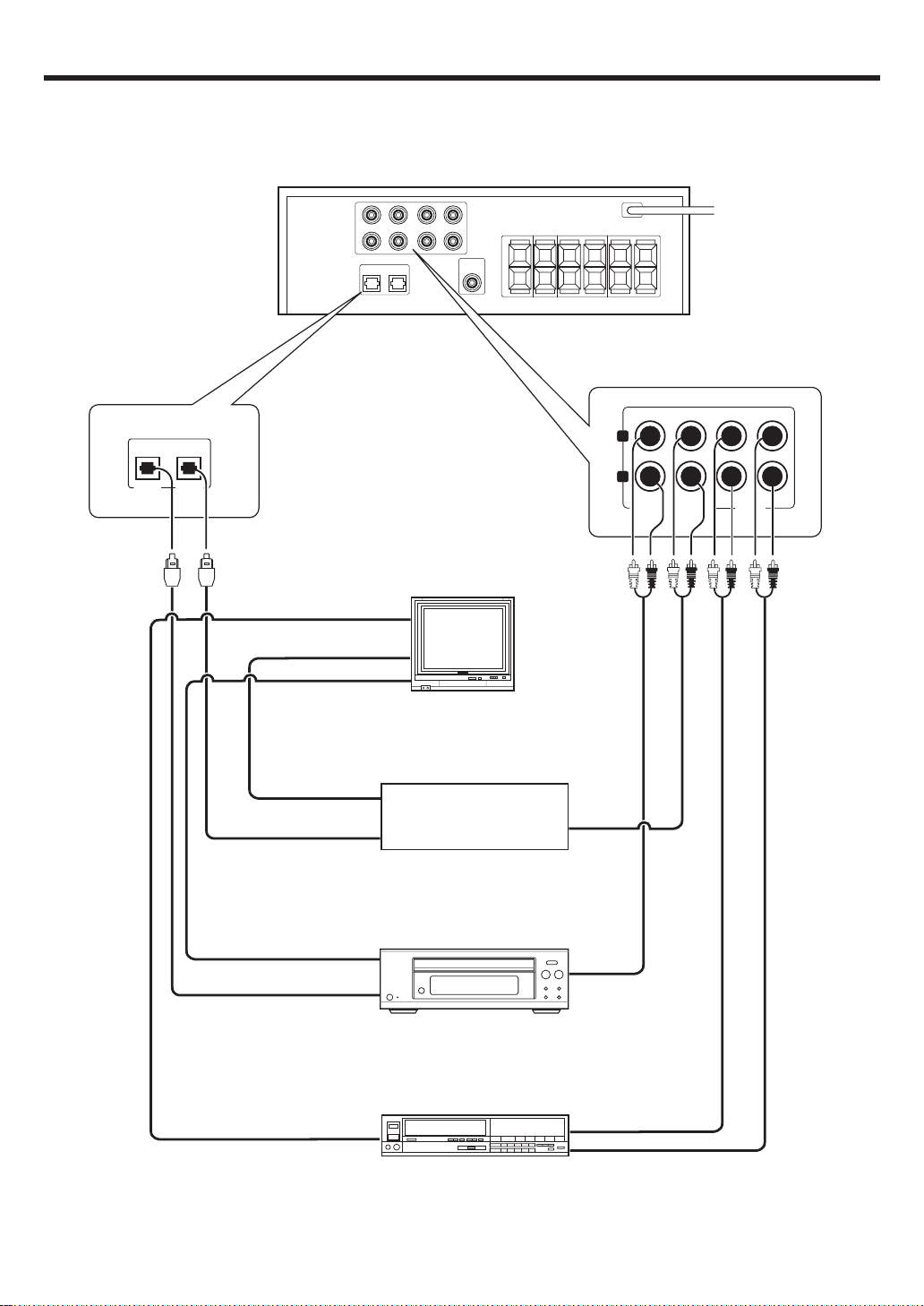
Connecting audio components
OPT 1 OPT 2
To AC wall outle
L
OUT
R
DVD/CD IN- VIDEO 2 IN VIDEO 1
Video input
(Yellow RCA pin cords)
VIDEO IN 1
VIDEO IN 2
VIDEO IN 3
OUT
Video output
Optical fiber cable
OPTICAL DIGITAL OUT
(AUDIO)
OUT
Video output
Optical fiber cable
OPTICAL DIGITAL OUT
(AUDIO)
Monitor TV
Satellite or component
with DTS, Dolby Digital,
or PCM DIGITAL OUT
DVD player (e.g. DVF-S500)
or CDplayer
Video deck
OUT
Audio
outputs
OUT
Audio
outputs
OUT
OUT
Video output
(Yellow RCA pin cords)
EN
10
IN
Audio inputs and outputs
Page 11
Setting up the system
Connecting the speakers ( for HTB-S500 system)
Connect terminals of same color between rear panel and speakers.
Also use speaker cord which have same colored tube as terminal.
White lined wire is for + polarity.
To AC wall outlet
KENWOOD
KENWOOD
Center Speaker
Subwoofer or
Back Surround Speaker
Use this terminal if you
wish to connect to a
Back Surround speaker
with the SETUP of "6CH BS".
SUB/W
BS
REARCENTER FRONT
R
R
L
KENWOOD KENWOOD
Right Left
Surround Speakers
L
KENWOOD KENWOOD
Right Left
Front Speakers
Supplied speaker seals
Front speakers and surround speakers have screw holes to fix to
speaker stand. If you don’t use these holes, stick supplied seals
to hide holes.
Supplied speaker cushions
Stick the supplied four cushions to the bottom of the speakers.
(except subwoofer) It is effective for slip-proof and deaden
vibrations of placed speakers.
11
EN
Page 12

Setting up the system
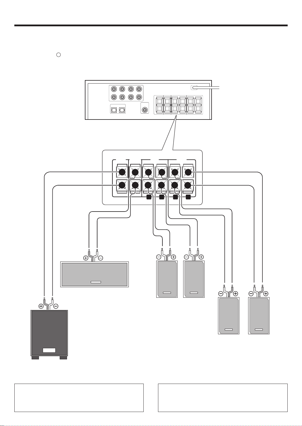
Connecting the speakers ( for KAF-S500 )
SUB
WOOFER
Powered subwoofer
When you connect Back Surround speaker to
SUB/W BS terminal, connect Powered
Subwoofer to this terminal.
To AC wall outlet
KENWOOD
SUB/W
BS
KENWOOD
Center Speaker
Subwoofer or Back Surround Speaker(option)
Recommend to connect Subwoofer to this terminal but
if you wish to connect to a Back Surround speaker
with the SETUP of "6CH BS", use this terminal.
REARCENTER FRONT
R
R
L
KENWOOD KENWOOD
Right Left
Surround Speakers
L
KENWOOD KENWOOD
Right Left
Front Speakers
12
EN
Page 13

Setting up the system
Connecting the terminals
1 Strip coating. 2 Push the lever.
3 Insert the cord. 4 Release the lever.
• Never short circuit the + and – speaker cords.
• If the left and right speakers are connected inversely or the speaker
cords are connected with reversed polarity, the sound will be
unnatural with ambiguous acoustic imaging. Be sure to connect the
speakers correctly.
Speaker impedance
After confirming the speaker impedance indications printed on the
rear panel of the amplifier, connect speakers with matching
impedance ratings. Using speakers with a rated impedance other
than that indicated on the rear panel of the amplifier could result
in malfunctions or damage to the speakers or receiver.
Speaker placement
KENWOOD
Center speaker
KENWOOD
Listening
position
Back surround
speaker
(option)
Subwoofer
KENWOOD
Front speakers
(L,R)
Surround
speakers
(L,R)
Front (left and right) speakers
Place at the front left and right of the listening position. Front speakers
are required for all surround modes.
Center speaker
Place front and center. This speaker stabilizes the sound image and
helps recreate sound motion. Required for surround playback.
Surround (left and right) speakers
Place at the direct left and right, or slightly behind, the listening
position at even heights, approximately 1 meter above the ears of the
listeners. These speakers recreate sound motion and atmosphere.
Required for surround playback.
Subwoofer
Reproduces powerful deep bass sounds.
Back surround speaker (option)
Place the speaker directly at the rear of the listening position. The
optimum position depends mainly on the room condition.
•Although the ideal surround system consists of all the speakers
listed above, if you don't have a center speaker or a subwoofer, you
can divide those signals between the available speakers in the
speaker settings steps to obtain the best possible surround
reproduction from the speakers you have available. %
13
EN
Page 14

S
AUX
OPTICAL
T
Setting up the system
r
Connecting to the FRONT AUX jacks
The FRONT AUX jacks are convenient for connection of video components
such as a camcorder or a video game.
PHONE
Optical fiber
cable
AUDIO -R
L -AUDIO -R
Preparing the remote control
Loading the batteries
1 Remove the cover. 2 Insert the batteries.
3 Close the cover.
• Insert two AAA-size (R03) batteries as indicated by the polarity
markings.
Operation
When the STANDBY indicator is lit, the power turns ON when you press
the POWER
press the key you want to operate.
Operating range
(Approx.)
key on the remote control. When the power comes ON,
Remote senso
DIGITAL
OUT
AUDIO
OUT
Camcorder, other
VCR, video game or
portable MD player
• To select the source connected to the FRONT AUX jacks select
FRONT AUX key. *
6 m
POWER
Infrared ray system
• When pressing more than one remote control key successively, press
the keys securely by leaving an interval of 1 second or more between
keys.
Notes
1. The supplied batteries may have shorter lives than ordinary batteries
due to use during operation checks.
2.When the remote-controllable distance gets shorter than before,
replace both batteries with new ones.
3.Placing the remote sensor in direct sunlight, or in direct light from a
high frequency fluorescent lamp may cause malfunction.
In such a case, c hange the location of the system installation to prev ent
malfunction.
EN
14
Page 15

Preparing for surround sound
Speaker settings
To enable you to obtain optimum enjoyment from the amplifier’s listening modes, make sure to complete the speaker settings (subwoofer,
front, center, surround and surround back speakers) as described below.
(POWER)
POWER
SET UP
TRIM%¥fi
If you purchase HTB-S500 system, you may skip step 2 to 4.
Original settings of this amplifier are adjusted to KSW-S500
speakers.
The original settings are
6ch AMP : 6ch SW Subwoofer : SW ON
Front : FRONT NML Center : CNTR NML
Sorround : SURR NML Back surround : BS NML
Subwoofer Re-Mix : REMIX ON
Turn on the power to this amplifier by pressing the
1
(POWER) key.
Press the SET UP key to enter the SET UP mode.
2
Use the TRIM%/ fi keys to select the “SP SETUP”
1 SP SETUP
2 TEST TONE
3 DISTANCE
4 DIMMER
5 EXIT
Press the SETUP key to select the 6ch AMP setting.
3
The Back Surround and Subwoofer output selections are displayed
as follows:
1 6ch SW : SUB/W BS speaker terminal will output
2 6ch BS : SUB/W BS speaker terminal will output Back
3 6ch OFF : It is not advisable to use SUB/W BS speaker
Subwoofer sound.
Surround sound. Subwoofer pre out will have
output from SW only.
terminal for this selection.
The flow of the SETUP is as follows:
SP SETUP TEST TONE DISTANCE DIMMER EXIT
6ch AMP setting
Subwoofer
Front
Center
Surround
Back
Surround
Subwoofer
Re-mix
Select a speaker system.
4
If you have THX certified speakers, please set them to NML.
1 Press the SETUP key again so that the subwoofer setting
indication “SW ON” appears.
DOLBY PLII
DTS -ES AAC
DISCRETE
MATRIX 6.1
ACTIVE EQ.
2 Use the TRIM%/fi keys to select the appropriate subwoofer
setting.
1 SW ON : Subwoofer setting mode to the amplifier is
2 SW OFF : Subwoofer setting mode to the amplifier is
•When the setting “SW OFF” is selected using the SET UP key,
the front speakers are automatically set to “FRONT LRG” and the
procedure skips to step 6.
Before step 6, press the SET UP key to accept the setting.
3 Press the SET UP key to accept the setting.
•The front speakers setting indication “FRONT” appears.
DOLBY PLII
DTS -ES AAC
DISCRETE
MATRIX 6.1
ACTIVE EQ.
4 Use the TRIM%/fi keys to select the appropriate front speak-
ers setting.
1 FRONT LRG : Large front speakers are connected
2 FRONT NML : Average size front speakers are
•For “FRONT LRG” and “SW ON” selection, no sound will be
heard from subwoofer speaker even when it is set to on.
However, if you select “REMIX ON” in step @ when subwoofer
is selected, you will be able to hear sound from the subwoofer.
5 Press the SET UP key to accept the setting.
•The center speaker setting indication “CNTR” appears.
MANUALAUTO
L
L R
C
C
R
LS RS
RS
BS
BS
LS
SW
SW
MUTEDOLBY DEX NEO:6 DSP TS DIGITAL ST.
ON.
OFF.
MUTEDOLBY DEX NEO:6 DSP TS DIGITAL ST.
Front
Center
Surround
Back
Surround
Subwoofer
AUTO
AUTO
Dimmer
LFE SW
LS S BS RS
L
LFE SW
LS S BS RS
to the amplifier.
connected to the amplifier.
L
CR
C R
Use the TRIM%/fi keys to select the speakers.
Press the SETUP key to proceed to the next SETUP selection.
Continued to next page
15
EN
Page 16

Preparing for surround sound
6 Use the TRIM%/fi keys to select the appropriate center
speaker setting.
If you selected “LRG” as the front speakers setting,
1 CNTR NML : An average size center speaker is
connected to the amplifier.
2 CNTR LRG : A large center speaker is connected
to the amplifier.
3 CNTR OFF : Center speaker setting mode to the
amplifier is OFF.
If you selected “NML” as the front speakers setting,
1 CNTR ON : Center speaker setting mode to the
receiver is ON.
2 CNTR OFF : Center speaker setting mode to the
receiver is OFF.
7 Press the SET UP key again to accept the setting.
•The surround speaker indication “SURR” appears.
8 Use the TRIM%/fi keys to select the appropriate surround
speaker setting.
If you selected “LRG” as the center speaker setting,
1 SURR NML : Average size surround speakers are
connected to the amplifier.
2 SURR LRG : Large surround speakers are
connected to the amplifier.
3 SURR OFF : Surround speaker setting mode to
the amplifier is OFF.
If you selected other than “LRG” as the center speaker setting,
1 SURR ON : Surround speaker setting mode to the
amplifier is ON.
2 SURR OFF : Surround speaker setting mode to the
amplifier is OFF.
•When the setting “SURR OFF” is selected, by pressing the SET
UP key in step 9 the procedure skips to step @. But if “SW
OFF” is selected, press the SET UP key to skip to step 5.
9 Press the SET UP key again to accept the setting.
•The back surround speaker setting indication “BS” appears.
0 Use the TRIM%/fi keys to select appropriate surround back
speaker setting.
If you selected “LRG” as the surround speaker setting,
1 BS NML : Average size back surround speaker is
connected to the amplifier.
2 BS LRG : Large back surround speaker is con-
nected to the amplifier.
3 BS OFF : Back surround speaker setting mode to
the amplifier is OFF.
DOLBY PLII
DTS -ES AAC
DISCRETE
MATRIX 6.1
ACTIVE EQ.
MUTEDOLBY DEX NEO:6 DSP TS DIGITAL ST.
AUTO
L
CR
LFE SW
LS S BS RS
If you selected “NML” as the surround speaker setting,
1 BS NML : Back surround speaker setting mode
to the amplifier is ON.
2 BS OFF : Back surround speaker setting mode
to the amplifier is OFF.
! Press the SET UP key again to accept the setting.
•The subwoofer remix setting indication ”REMIX” appears.
•If subwoofer is turned off, subwoofer re-mix setting is not visible.
DOLBY PLII
DTS -ES AAC
DISCRETE
MATRIX 6.1
ACTIVE EQ.
MUTEDOLBY DEX NEO:6 DSP TS DIGITAL ST.
AUTO
@ Use the TRIM%/fi keys to select the appropriate subwoofer
re-mix setting.
1 REMIX ON : Subwoofer re-mix setting mode to
the amplifier is ON.
2 REMIX OFF : Subwoofer re-mix setting mode to
the amplifier is OFF.
When “REMIX ON” is selected, bass sound of other channel
will be added into Subwoofer or bass sound of Subwoofer
will be added into other channel to increase deep bass
performance.
# Press the SET UP key again to return to the
2.
•The receiver enters the speaker volume level adjustment mode.
•In steps 5 and 6 , indications appear only for the selected
channels of the speakers that require adjusting.
Adjust the speaker volume level.
5
From your usual listening position, adjust the volume levels. The
volume levels from each speaker should be the same.
1 Press the SET UP key and then use the TRIM%/fi keys to
select TEST TONE.
2 Press the SET UP key for the following displays:
The selection of AUTO or MANUAL is done by the TRIM%/fi
keys.
1 AUTO
2 MANUAL
3 Press the SET UP key again to begin TEST TONE.
Use the TRIM%/fi keys to adjust the volume level of the test
tone output from the speaker channel to be adjusted.
For AUTO selection, the first test tone is heard from the front left
speaker for 3 seconds. The next test tone is heard from the
speakers in the following sequence for 3 seconds each.
LC RRS
BSLSSW
The channel indication blinks while the test tone is being output.
DOLBY PLII
DTS -ES AAC
DISCRETE
MATRIX 6.1
ACTIVE EQ.
MUTEDOLBY DEX NEO:6 DSP TS DIGITAL ST.
AUTO
•If you change the volume level settings for the speakers while
listening to music, the settings referred to on this page are also
changed.
•If the speaker setting selects are OFF, the speaker level settings
are reset.
For “MANUAL” selection, press the FRONT, CENTER, REAR
or SW keys to select the speaker channel and then adjust the
volume level by pressing TRIM%/fi keys.
L
CR
LFE SW
LS S BS RS
L
CR
LFE SW
LS S BS RS
16
EN
Page 17

Preparing for surround sound
• Press the FRONT key each time to select Front L or Front R
channel.
• Press the CENTER or SW key to select center or subwoofer
channel.
• Press the REAR key to select surround channel.
And use the REAR key for the following displays.
1 LS : Surround L channel.
2 BS : Back surround channel.
3 RS : Surround R channel.
4 Press the SET UP key again.
•The test tone is turned off and return to the main setup displays.
Input the distance to the speakers.
6
1 Measure the distance from the listening position to each of
the speakers.
Jot down the distance to each of the speakers.
Distance to Front left speaker (L) : ____ meters
Distance to Center speaker (C) : ____ meters
Distance to Front right speaker (R) : ____ meters
Distance to Surround right (RS) : ____ meters
Distance to Back Surround (BS) : ____ meters
Distance to Surround left (LS) : ____ meters
Distance to Subwoofer (SW) : ____ meters
2 Press theTRIM%/fi keys to select the “DISTANCE” on setup
displays and press the SETUP key again.
3 Use the SET UP key to select the speakers and the TRIM%/fi
keys to adjust the distance to the front speakers.
The speaker indicator to be adjusted blinks.
DOLBY PLII
DTS -ES AAC
DISCRETE
MATRIX 6.1
ACTIVE EQ.
MUTEDOLBY DEX NEO:6 DSP TS DIGITAL ST.
AUTO
L
C R
LFE SW
LS S BS RS
•The allowable setting range is 0.3 to 9.0 m, adjustable in 0.3 m
increments.
4 Repeat steps 3 to input the distance for each of the speakers.
5 Press the SET UP key again to return to main setup displays.
•The speakers you have selected should appear on the display.
Confirm that all the speakers have been correctly selected.
17
EN
Page 18

Normal playback
Preparing for playback
Some preparatory steps are needed before starting playback.
(POWER)
Turning on the amplifier
1 Turn on the power to the related components.
2 Turn on the power to this amplifier by pressing the
(POWER) key.
Selecting the input mode
If you have selected a component connected to the DVD/CD, VIDEO 2
or FRONT AUX jacks, make sure that the input mode setting is correct
for the type of audio signal to be used. 9
INPUT MODE
POWER
Listening to a source component
VOLUME CONTROLINPUT SELECTOR
INPUT SELECTOR
VOLUME%¥fi
Use the INPUT SELECTOR knob (or INPUT SELECTOR keys)
1
and AV AUX key to select the source you want to listen to.
Selecting a source using each key.
1 “DVD/CD”
2 “VIDEO 1”
3 “VIDEO 2“
4 “FRONT AUX”
Start playback from the selected source.
2
Use the VOLUME CONTROL knob (or VOLUME CONTROL
3
%¥fi keys) to adjust the volume.
18
EN
Page 19

Normal playback
L
Adjusting the sound
VOLUME CONTRO
Muting the sound
The MUTE key lets you mute the sound of the speakers.
Press the MUTE key.
Blinks
ACTIVE EQ.
PHONES
POWER
ACTIVE EQ
SOUND
TRIM%¥fi
VOLUME%¥fi
MUTE
Adjusting the TONE
You can adjust the sound quality when the receiver is in the PCM stereo
mode, analog stereo mode.
1 Press the SOUND key to select the SOUND mode.
When input signal is Dolby Digital and STEREO
1 T.SURR ON or OFF : SRS TruSurround
2 TONE : Tone
3 NIGHT ON or OFF : Midnight mode
When input signal is except STEREO
TONE : Tone
• For other input signal, some of mode will not be displayed.
2 Use the TRIM%/fi keys to select TONE and then press SOUND
key.
DOLBY PLII
DTS -ES AAC
DISCRETE
MATRIX 6.1
ACTIVE EQ.
MUTEDOLBY DEX NEO:6 DSP TS DIGITAL ST.
L
CR
AUTO
LFE SW
LS SBS RS
DOLBY PLII
DTS -ES AAC
DISCRETE
MATRIX 6.1
ACTIVE EQ.
MUTEDOLBY DEX NEO:6 DSP TS DIGITAL
To cancel
Press the MUTE key again so that the “MUTE” indicator goes off.
•MUTE ON can also be deactivated by turning the pressing
VOLUME CONTROL knob (or VOLUME %/fi keys).
ACTIVE EQ mode
You can enjoy a more impressive sound effect when ACTIVE EQ is
turned ON during Dolby Digital and DTS playback and, when in PCM and
analog stereo mode.
Press the ACTIVE EQ key for the following selections;
1EQ CINEMA : Effective when watching a movie.
(The ACTIVE EQ. indicator lights up.)
2EQ MUSIC :Effective when listening to music.
(The ACTIVE EQ. indicator lights up.)
3EQ OFF :The ACTIVE EQ function is turned OFF.
(The ACTIVE EQ. indicator goes off.)
• ACTIVE EQ function will not be available when during recording
or DTS-ES MATRIX is ON, and during 96kHz LPCM playback.
Listening with headphones
1 Connect headphones to the PHONES jack.
PHONES
• Headphones with a stereo mini plug can be connected.
• The sounds from all speakers are cut off.
2 Use the VOLUME CONTROL knob (or VOLUME%/fi keys) to
adjust the volume.
3 When in TONE ON selection, press the SOUND key for the
following displays.
BASS : Select this to adjust the low frequency range.
TREBLE: Select this to adjust the high frequency range.
4 Use the TRIM%/fi keys to adjust the sound quality.
DOLBY PLII
DTS -ES AAC
DISCRETE
MATRIX 6.1
ACTIVE EQ.
MUTEDOLBY DEX NEO:6 DSP TS DIGITAL ST.
AUTO
L
CR
LFE SW
LS SBS RS
•The bass and treble levels are adjustable from -10 to +10 in 2 step
increments.
•The adjustment item is displayed for approximately 20 seconds.
19
EN
Page 20

Recording
Recording audio (analog sources)
INPUT SELECTOR
INPUT SELECTOR
Recording a music source
1 Use the INPUT SELECTOR knob (or INPUT SELECTOR keys) to
select the source (other than “VIDEO 1”) you want to record.
• Connect analogue audio outputs to this Amplifier. 0
2 Start playback, then start recording.
20
EN
Page 21

Ambience effects
This receiver is equipped with listening modes that allow
you to enjoy an enhanced sonic ambience with a variety of
video sources.
In order to obtain the optimum effect from the surround
modes, make sure to input the proper speaker settings
beforehand. %
Surround modes
Dolby Digital
The Dolby Digital surround format lets you enjoy up to 5.1 channels
of digital surround sound from Dolby Digital program sources (such as
Laserdisc or DVD software marked
ous Dolby surround, Dolby Digital provides even better sound quality,
greater spatial accuracy, and improved dynamic range.
Although a full set of speakers (front left, right, and center, surround
left and right, and a subwoofer) is required for true 5.1 channel Dolby
Digital surround sound, this receiver lets you enjoy Dolby Digital (and
Dolby Surround) program sources, even if you connect only the front
speakers.
Subwoofer
(SW)*
KENWOOD
Surround
speakers
(L,R)
Center speaker
KENWOOD
KENWOOD
*Optional in this mode.
Manufactured under license from Dolby Laboratories. “Dolby”, “Pro
Logic”, “Surround EX” and the double-D symbol are trademarks of
Dolby Laboratories.
). Compared with previ-
Front speakers
(L,R)
DTS
The DTS multi-channel audio format is available on CD, LD and DVD
software. DTS is strictly digital format and cannot be decoded inside
most CD, LD or DVD players. For this reason. If you attempt to listen
to DTS encoded software through the analog output of your new CD,
LD or DVD player, you will experience digital noise in most cases. This
noise can be quite loud if the analog output is connected directly to a
high power amplification system. Proper measures for playing the
digital output as described below should be taken to avoid this
situation. To enjoy DTS Digital Surround playback, an external 5.1
channel DTS Digital Surround decoder system or an amplifier with a
built-in DTS Digital Surround decoder must be connected to the digital
output (S/P DIF, AES/EBU or TosLink) of a CD, LD or DVD player.
All models are incorporated with the DTS decoder.
KENWOOD
Center speaker
KENWOOD
Front speakers
(L,R)
Subwoofer
(SW)*
KENWOOD
Surround
speakers
(L,R)
*Optional in this mode.
Note
*LFE = Low Frequency Effects. This channel delivers separate nondirectional bass signals to the subwoofer for more dynamic deep bass
sound effects.
DTS has a .1 or LFE channel.
The indication “LFE” appears in the display when a signal is being
input for this channel.
Dolby PRO LOGIC II
Dolby Pro Logic II was designed specifically to provide a new sense
of spatiality, directionality and articulation of sounds from Dolby
Surround encoded sources (such as video and Laserdisc software
marked
feedback logic design, a matrix surround decoding and the decoding
of stereo, full bandwidth surround outputs. The PRO LOGIC
programmed into this receiver are “MOVIE”, “MUSIC” and “PRO
LOGIC”. The “MOVIE” mode of the PRO LOGIC
characteristics to produce a calibrated.
). This is achieved with an intelligent, built-in
II modes
II has preset
“DTS”, “DTS-ES Extended Surround” and “Neo:6” are trademarks
of Digital Theater Systems, Inc.
Note
*LFE = Low Frequency Effects. This channel delivers separate nondirectional bass signals to the subwoofer for more dynamic deep bass
sound effects.
Subwoofer
(SW)
KENWOOD
Surround
speakers
(L,R)
KENWOOD
Center speaker
KENWOOD
Front speakers
(L,R)
21
EN
Page 22

l
.
l
l
Ambience effects
DSP mode
The DSP mode lets you add the atmosphere of a live concert or hall
to almost any type of program source. These modes are particularly
effective when used with stereo program sources, like CD, television,
and FM radio. You might enjoy trying the ARENA, JAZZ CLUB,
THEATER, STADIUM or DISCO mode the next time you watch a
concert or sporting event!
KENWOOD
Center speaker
KENWOOD
Front speakers
(L,R)
Subwoofer
(SW)
KENWOOD
Surround
speakers
(L,R)
What's DSP?
DSP stands for Digital Signal Processor.
The way a sound is heard in an actual environment depends on a
variety of different factors. One of the most important is reverberation
(the act of decaying elements of sound echoing in various places).
The DSP modes produce the feeling of presence by using the DSP to
create reverberation, without spoiling the sound quality of the original
signal.
Dolby Digital EX
Dolby Digital EX is an extension of Dolby Digital technology, Dolby
Digital EX creates six full-bandwidth output channels from 6.1-channel sources. This is done using a matrix decoder that derives three
surround channels from the two in the original recording.
This is achieved by using three different surround signals, Left
Surround , Right Surround, and Back Surround, each driving its own
array of speakers. Think of it as adding a center channel for the rear
speakers, which give more diffuse and natural surround effect, even
if you wanted the ability to completely encircle the audience with
sound, positioning sound effects exactly where they wolud be heard
in real life. For best results, Dolby Digital EX should be used with
movie soundtracks recorded with Dolby Digital Surround EX which
contain a digital flag that will automatically activate this feature.
However, for titles released prior to late 2001, this feature has to be
activated manually.
Although a full set of speakers (front left and right, center, surround
left and right, back surround and a subwoofer) are required for true 6.1
channel Dolby Digital surround EX sound, this receiver lets you enjoy
Dolby Digital (and Dolby Surround) program sources, even if you
connect only the front speakers.
DTS-ES
DTS-ES (Digital Theater System-Extended Surround) presents 6.1
channels surround system with additional Back Surround channe
which evolved from the conventional 5.1 channels surround system
DTS-ES format that was recorded in DVD, CD or LD comprises of two
modes. DTS-ES Discrete 6.1 produce the discrete back surround
which is completely independent and DTS-ES Matrix 6.1 produces
the back surround which synthesised within the left and right surround
channels using matrix technology. DTS-ES has perfect compatibility
with the conventional 5.1 channels surround system. 6.1 channels
surround with an additional back surround presents a more natura
presence and surround effects by increasing the impression of the
sound image from back. Programs which are recorded using DTS-ES
technology consist of information flags which will be able to contro
the Discrete and Matrix mode. Thus, it can automatically select the
best matched mode.
Neo:6
Neo:6 is a new technology which was developed by DTS. It can
produce high grade 6 channels surround with an astonishing fidelity
from 2 channels content. Neo:6 has 2 mode, "CINEMA" mode is for
movie playback and "MUSIC" mode is for music playback.
DTS has a .1 or LFE channel.
The indication “LFE” appears in the display when a signal is being
input for this channel.
KENWOOD
Center speaker
KENWOOD
Front speakers
(L,R)
Back surround
speaker
Subwoofer
(SW)*
KENWOOD
Surround
speakers
(L,R)
*Optional in this mode.
KENWOOD
Center speaker
KENWOOD
Front speakers
(L,R)
Back surround
speaker
Subwoofer
(SW)*
KENWOOD
Surround
speakers
(L,R)
*Optional in this mode.
Although only Dolby Digital soundtracks incorporate a separate low
frequency channel, connecting a subwoofer will also improve deep
bass performance in the other surround modes.
The indication “LFE” appears in the display when a signal is being
input for this channel.
EN
22
Page 23

Ambience effects
Surround play
The DTS compatible models can reproduce a CD, DVD, or LD carrying the
DTS mark.
DOLBY DIGITAL can be used when playing DVD or LD software bearing
the
DOLBY PRO LOGIC can be used when playing video, DVD, or LD
software bearing the mark.
Preparations
•Turn ON related components.
•Complete “Preparing for surround sound” (speaker settings). %
•Use the INPUT SELECTOR knob (or INPUT SELECTOR keys) to select
the component you wish to play back with surround sound.
•Use the INPUT MODE key to select the input mode (analog or digital)
for the source you wish to play back. 9
•Noise will be produced when a DTS source is played by selecting the
analog input.
1
2
mark and DOLBY DIGITAL format digital broadcasts (etc.).
INPUT SELECTOR
INPUT MODE
INPUT SELECTOR
STEREO
LISTEN MODE
STEREO
LISTEN MODE
Start playing the video software.
Use the LISTEN MODE key to select the listening mode.
The listening mode settings are stored separately for each input. If
the input mode is set to full auto the receiver selects the optimal
listening mode automatically based on the type of input signal and
the speaker settings.
Each press of the LISTEN MODE key switches the setting as
listed below.
The listening mode settings are different depending on the type
of input signal.
Dolby Digital Surround EX compliant disc :
Dolby Digital Surround EX compliant disc contains the identification
signals. When you choose FULL AUTO during “Input mode settings” (9), this amplifire detects the identification signals and
change the LISTEN mode to the DOLBY D EX(Dolby Digital Surround
EX mode) automatically.
But sometimes we find some discs which is Dolby Digital Surround
EX compliant disc but it does not contain the identification signals.
If you find the notice like “Surround EX” on the label of disc or
package, you can choose DOLBY D EX then you can enjoy Dolby
Digital Surround EX sound.
When the DOLBY DIGITAL EX or DOLBY DIGITAL signal is
input :
(The DOLBY D or DOLBY PLII , indicator lights up.)
1 DOLBY D : DOLBY DIGITAL EX surround.
2 DOLBY D : DOLBY DIGITAL surround.
3 MOVIE : PRO LOGIC II surround MOVIE mode.
4 PRO LOGIC : PRO LOGIC II surround PRO LOGIC mode.
5 STEREO : Normal stereo playback.When you select
“DOLBY D” will be displayed.
DOLBY PLII
DTS -ES AAC
DISCRETE
MATRIX 6.1
ACTIVE EQ.
(The DOLBY D EX indicator lights up.)
When DOLBY DIGITAL signal is input or
Back surround speaker is OFF, this menu
will not be displayed.
(The DOLBY D indicator lights up.)
(The DOLBY PLII indicator lights up.)
(The DOLBY PL indicator lights up.)
DOLBY DIGITAL
MUTEDOLBY D NEO:6 DSP TS DIGITAL ST.
AUTO
LFE SW
LS SBS RS
When the DTS or DTS-ES (matrix or discrete) signal is input :
1 DTS : DTS 5.1ch surround mode.
2 MTRX 6.1 : DTS 6.1ch MATRIX surround mode.
3 DSCRT 6.1 : DTS 6.1ch DISCRETE surround mode.
4 STEREO : Normal stereo playback.
(DTS indicator lights up.)
(DTS-ES and MATRIX 6.1 indicators light up.)
(DTS-ES and DISCRETE 6.1 indicators light up.)
When the analog signal or the digital signal (except for
DOLBY DIGITAL or DTS signal) is input :
1 MOVIE : PRO LOGIC II surround MOVIE mode.
2 MUSIC : PRO LOGIC II surround MUSIC mode.
3 PRO LOGIC : PRO LOGIC II surround PRO LOGIC mode.
4 CINEMA : NEO:6 surround.
5 MUSIC : NEO:6 surround.
6 ARENA : DSP surround ARENA mode.
7 JAZZ CLUB : DSP surround JAZZ CLUB mode.
8 STADIUM : DSP surround STADIUM mode.
9 DISCO : DSP surround DISCO mode.
0 THEATER : DSP surround THEATER mode.
- STEREO : Normal stereo playback.
• Dolby Digital or DTS signal having more channels than the maximum
number of playback channels available using the receiver’s current
settings is input, downmixing is performed to match the number of
available speaker channels.
•The DSP mode selection is displayed for approximately 3 seconds.
Adjust the volume.
3
(The DOLBY PL II indicator lights up.)
(The DOLBY PL indicator lights up.)
(The DOLBY PL indicator lights up.)
(The NEO:6 indicator lights up.)
(The NEO:6 indicator lights up.)
(The DSP indicator lights up.)
(The DSP indicator lights up.)
(The DSP indicator lights up.)
(The DSP indicator lights up.)
(The DSP indicator lights up.)
L
CR
Continued to next page
EN
23
Page 24

Ambience effects
To charge to STEREO mode.
When you press the STEREO key, the LISTEN mode will be switched to
the STEREO mode.
During above STEREO mode, if you press STEREO key again, the
STEREO mode will be switched back to the LISTEN mode.
•If you switch to the STEREO mode using STEREO key, the DSP
mode will be turned off automatically.
•If you turn off and on the POWER, setting of the LISTEN mode will
not be loosed.
Notes
•Depending on the type of the signal or speaker setting, some listening
modes cannot be selected.
•When playback is started, the sound may be cut or interrupted before
the input source is confirmed as Dolby Digital.
SRS TruSurround play
When STEREO mode has been chosen in LISTEN MODE and input signal
is STEREO, you can enjoy surround effect by SRS TruSurround.
LISTEN MODE
SOUND
TRIM%¥fi
LISTEN MODE
Select STEREO mode using LISTEN MODE key. £
1
Press the SOUND key twice.
2
Use the TRIM %¥fi keys to select ON or OFF.
3
1 T.SURR ON : SRS TruSurround ON.
2 T.SURR OFF : SRS TruSurround OFF.
Press the SOUND key to return to the input indication.
4
•The adjustment item is displayed for approximately 20 seconds.
24
EN
Page 25

Convenient functions
CENTER
Adjustment of each channels’ level
You can adjust each channel’s level duning listening music.
1 Press the FRONT key to adjust FRONT L channel’s level.
DOLBY PLII
DTS -ES AAC
DISCRETE
MATRIX 6.1
ACTIVE EQ.
MUTEDOLBY DEX NEO:6 DSP TS DIGITAL ST.
2 Use the TRIM%/fi keys to adjust the sound level.
3 Press the FRONT key to adjust FRONT R channel’s level.
4 Use the TRIM%/fi keys to adjust the sound level.
5 Press the FRONT key to return to the input indication.
• The sound level is adjustable from -10 dB to +10dB in 1dB step
increments.
•The adjustment item is displayed for approximately 20 seconds.
• Use the CENTER or SW key to adjust sound level of center or
subwoofer channel.
•Use the REAR key to adjust sound level of surround channel.
And use the REAR key for the following displays.
1 LS : Surround L channel.
2 BS : Surround back channel.
3 RS : Surround R channel.
Midnight mode (Dolby Digital mode only)
When watching movies at night , you might not be able to raise the volume as
loud as normal. Midnight mode compresses the dynamic range of previously
specified heavy sound passage of the Dolby Digital sound track (like scenes with
sudden increases in volume) to minimize the difference in volume between the
scenes with heavy sound passage and scenes with normal sound passage. This
makes it easy to hear all of the sound track, even when listening at low volumes.
1 Press the SOUND key to enter the SOUND mode.
•This can be selected only if DVD/CD, VIDEO 2 or FRONT AUX is
selected as the source and the listen mode is set to “DOLBY DIGITAL.”
2 Use the TRIM%/fi keys to select the “NIGHT” and then press
the SOUND key.
3 Use the TRIM%/fi keys to select ON or OFF.
1 NIGHT ON : Midnight mode ON.
2 NIGHT OFF : Midnight mode OFF.
REAR
SOUND
SWFRONT
TRIM%¥fi
AUTO
L
CR
LFE SW
LS SBS RS
Display dimmer adjustment
The dimmer function lets you select the brightness of the amplifier's
display. You might find this useful if you darken your room to watch
movies or listen to music.
1 Press the SET UP key to enter the SETUP mode.
2 Use the TRIM%/fi keys to select the “DIMMER”.
3 Press the SET UP key again so that the dimmer setting indication
appears.
Select the brightness level you find most pleasing using TRIM
(%/fi ) keys.
1 DIMMER H : Bright
2 DIMMER L : Dark
4 Press the SET UP key to return to the “DIMMER”.
5 Use the TRIM%/fi keys to select the “EXIT”.
6 Press the SET UP key to return to the input indication.
Sleep timer (SLEEP)
Set the number of minutes after which the unit to be turned OFF.
Connect the related component under reference to “Connecting
audio components”.
Press the SLEEP key to select the time.
•Each press increases the timer period by 10 minites.
The sleep timer can be setup to 90 minites.
10 = 20 = 30 = .... = 80 = 90 = OFF = 10 = 20 = ....
The sleep timer indicator will be lit.
DOLBY PLII
DTS -ES AAC
DISCRETE
MATRIX 6.1
ACTIVE EQ.
MUTEDOLBY DEX NEO:6 DSP TS DIGITAL ST.
AUTO
L
CR
LFE SW
LS S BS RS
•The sysytem has been setup so taht the display is dimmered automatically while the sleep timer is activated.
•Press the SLEEP key while the sleep timer is activated to check the
remaining time.
To cancel
Turn the amplifier OFF or press the SLEEP key until the sleep time is
caucelled.
96kHz LPCM playback
The amplifier is compatible with the 96kHz LPCM playback. To play a
96kHz DVD, set the listen mode to “STEREO”.
•In FULL AUTO input mode the listen mode will automatically be
STEREO.
•When in D MANUAL input mode (listen mode is not STEREO), “96kHz
LPCM” will appear in the display and no sound can be heard from the
speakers.
Press the LISTEN MODE or STEREO key (the listen mode changes to
the STEREO mode) to output sound from the speakers.
4 Press the SOUND key to returm to the input indication.
•The adjustment item is displayed for approximately 20 seconds.
•Some Dolby Digital software may not be compatible with the
Midnight mode.
25
EN
Page 26

Basic remote control operations for other components
The remote control supplied with this amplifier is also
capable of controlling components from a variety of
manufacturers once you register the appropriate setup codes
into the remote control unit.
Low battery warning
Replace all two batteries with new ones when you notice a shortening
of the distance from which the remote control will operate. The
remote control is designed to retain setup codes in memory while you
change batteries.
Registering setup codes for other components
Refer to below list about the components which can be
registered to INPUT SELECTOR keys of the remote control.
You can register to the ‡ marked INPUT SELECTOR keys of
the remote control.
INPUT SELECTOR
keys
VIDEO ‡
TV ‡
Satellite ‡
Cable ‡
DVD player ‡
CD player ‡
SOURCE
INPUT SELECTOR
Numeric keys
DVD/CD VIDEO1 VIDEO2 TV
POWER
TV
Press the registered INPUT SELECTOR key and then press the
3
SOURCE
control turns on or press the TV
key to check that the component you want to
key to check that the TV
turns on.
If the component does not react, and there is more than one
setup code, enter another setup code and try again.
• If the component is already on, pressing the SOURCE
turn it off.
Repeat steps 2 to 3 to register additional components until
4
key will
Checking the codes .
If you want to know which number was set.
1 After registering the setup code, press and hold the ENTER
key and then press the INPUT SELECTOR key.
• LED will blink twice as confirmation.
2 Press the ON SCREEN key.
• LED will blink according to first, second and third digit for the current
setup code.
• In case of digit 0, the LED will blink ten times.
Example : If the registered SETUP code is “028”, the LED will blink
• If the ON SCREEN key is not pressed within ten second, this
function will be cancelled.
Note
Although each setup code is designed to work with a number of
different models, certain codes may not work with some models.
(Also, certain codes may only operate some of the functions available
on a given model.)
ten times, two times and eight times.
5¥∞¥2¥3
ENTER
Find the setup code of the component to be registered.
1
•Refer to the setup code lists to find the setup code for the
component to be registered. •
Example: To register a DVD made by KENWOOD, you would enter
“005”.
Input Component Maker Code Key
(DVD) DVD player KENWOOD 005 DVD/CD
Registering components for the remote control.
2
1 During press and hold the ENTER key, press one of the INPUT
SELECTOR key or TV key which you want to register.
• LED will blink twice as confirmation.
2 Press the Numeric keys to enter the three-digit setup code.
• LED will blink once as confirmation.
ON SCREEN
If no response after registering setup codes.
1 During press and hold the ENTER key, press any of the INPUT
SELECTOR keys or TV key which you want to register.
• LED will blink twice as confirmation.
2 Press the 5 key until the component you want to control turns
on.
3 Press the ENTER key.
• If you press the 5 key after turn on the component you want to
control, press ∞ key to return to previous step.
26
EN
Page 27

Basic remote control operations for other components
Operating other components
This operation lets you operate the registered components.
SOURCE
INPUT SELECTOR
Use the INPUT SELECTOR keys to select the component you
1
POWER
desire.
• Pressing the INPUT SELECTOR keys also changes the input
selector on the amplifier.
Press the SOURCE key.
2
Press the operation keys you desire. ¤‹
3
The remote control mode remains at the selected input. If you
wish to operate another component, repeat step 2 or 3.
27
EN
Page 28

Basic remote control operations for other components
Setup code chart
TV setup codes
Maker Setup codes
AOC 000, 001
ADMIRAL 031, 041
AIKO 014
AKAI 001
ALARON 026
AMBASSADOR 024
AMERICA ACTION 027
AMPRO 043
ANAM 027, 086, 087, 088
AUDIOVOX 014, 027, 030, 034
BAYSONIC 027
BELCOR 000
BELL&HOWELL 001, 016, 019
BRADFORD 027
BROCKWOOD 000
BROKSONIC 028, 031
CANDLE 001, 011
CARNIVAL 001
CARVER 010
CELEBRITY 050, 089
CINERAL 014, 030
CITIZEN 001, 006, 011, 012, 014
CONCERTO 011
CONTEC 027
CRAIG 027, 082
CROSLEY 010
CROWN 006, 027
CURTIS MATHES 001, 006, 007, 008, 010, 011,
CXC 027
DAEWOO 000, 006, 014, 030, 034, 035
DAYTRON 000
DENON 016
DUMONT 000, 002
DWIN 036, 044
ELECTROBAND 050, 089
EMERSON 000, 006, 019, 024, 025, 026,
ENVISION 001
FISHER 019
FUJITSU 026
FUNAI 023, 026, 027
FUTURETECH 027, 083
GE 004, 007, 008, 025, 029, 030,
GIBRALTER 000, 001, 002
GOLDSTAR 000, 001, 011, 025
GRADIENTE 009, 011
GRUNPY 026, 027
HALLMARK 025
HARLEY DAVIDSON 026
HARMAN/KARDON 010
HAVARD 027
HITACHI 011, 016, 018
INFINITY 010
INTEQ 002
JBL 010
JCB 050, 089
JVC 009, 085
EN
28
012, 016, 019, 022, 030, 032,
038, 040, 041
027, 028, 029, 031, 034, 035
038, 040, 041
Maker Setup codes
KEC 027
KTV 001, 006, 027
KENWOOD 000, 001, 016
LG 011
LOGIK 001, 016
LUXMAN 011
LXI 007, 010, 019, 020, 025
MAGATRON 016, 025
MAGNAVOX 001, 010, 026
MAJESTIC 001, 016
MARANTZ 001, 010
MATSUSHITA 042
MEMOREX 011, 017, 019, 025, 031, 042
MGA 000, 001, 017, 025
MIDLAND 002, 006, 007, 008, 035
MINUTZ 004
MITSUBISHI 000, 017, 025, 041
MOTOROLA 041
MTC 000, 001, 011, 012
MULTITECH 027
NAD 020, 022, 025
NEC 000, 001, 011
NTC 014
NIKKO 001, 014, 025
ONWA 027
OPTIMUS 019, 022, 042
OPTONICA 021, 041
ORION 026, 028, 031
PANASONIC 008, 042, 081
PENNEY 000, 001, 004, 006, 007, 008,
011, 012, 020, 025, 040
PILCO 000, 001, 010, 016, 031
PHILIPS 010
PILOT 000, 001, 006
PIONEER 022
PORTLAND 000, 006, 014
PRISM 003, 008
PROSCAN 007
PROTON 025, 032
PULSAR 000, 002, 083
QUASAR 008, 021, 042
RCA 000, 007, 008, 013, 037, 038,
039, 040, 041
RADIO SHACK 000, 001, 006, 007, 011, 019,
021, 025, 027
REALISTIC 000, 001, 006, 011, 019, 021,
025, 027
RUNCO 001, 002, 033
SAMPO 001, 006
SAMSUNG 000, 001, 011, 012, 025, 084
SAMSUX 006
SANSEI 030
SANSUI 031
SANYO 019
SCIMITSU 000
SCOTCH 025
SCOTT 000, 025, 026, 027, 028
SEARS 007, 010, 011, 019, 020, 023,
025, 026
SEMIVOX 027
SEMP 020
SHARP 006, 021, 041
SHOGUN 000
Page 29

Basic remote control operations for other components
TV setup codes
Maker Setup codes
SIGNATURE 001, 016
SONY 050, 089
SOUNDESIGN 025, 026, 027
SQUAREVIEW 023
SSS 000, 027
STARLITE 027
SUPREME 050, 089
SYLVANIA 001, 010
SYMPHONIC 023
TANDY 041
TECHNICS 008, 042
TECHNOI ACE 005, 026
TECHWOOD 008, 011
TEKNIKA 000, 001, 006, 010, 011, 012,
014, 016, 017, 026, 027
TELEFUNKEN 011, 015
TMK 011, 024, 025
TOSHIBA 012, 019, 020
TOTEVISION 006
VECTOR RESEARCH 001
VICTOR 009
VIDIKRON 010
VIDTECH 000, 025
WARDS 000, 001, 004, 010, 011, 016,
021, 025, 026
WESTINGHOUSE 031, 034, 035
YAMAHA 000, 001
ZENITH 001, 002, 014, 016, 031
VIDEO setup codes
Maker Setup codes
ADMIRAL 021, 027, 077
ADVENTURA 006
AIKO 025
AIWA 005, 006
AKAI 002, 070
AMERICA ACTION 025
AMERICA HIGH 004
ASHA 023
AUDIOVOX 005
BEAUMARK 023
BELL&HOWELL 017
BROCKSONIC 021
BROKSONIC 014, 018, 020, 021
CCE 015, 025
CALIX 005
CANON 004
CARVER 016
CINERAL 025
CITIZEN 005, 025
COLT 015
CRAIG 005, 012, 015, 023, 024
CURTIS MATHES 002, 004, 013, 028, 070, 079
CYBERNEX 023
DAEWOO 010, 025
DENON 008
DYNATECH 006
ELECTROHOME 005
ELECTROPHONIC 005
EMEREX 012, 026
EMERSON 005, 006, 009, 014, 018, 020
021, 025
Maker Setup codes
FISHER 012, 017
FUJI 003, 004
FUNAI 006
GE 004, 013, 023, 027, 077
GARRARD 006
GOLDSTAR 000, 005
GRANDIENTE 006
HI-Q 012
HARLEY DAVIDSON 006
HARMAN/KARDON 000, 016
HARWOOD 015
HEADQUARTER 011
HITACHI 002, 006, 008, 070
JVC 001, 002, 070
JENSEN 002, 070
KEC 005, 025
KLH 015
KENWOOD 000, 001, 002, 070
KODAK 004, 005
LXI 005
LIOYD’ S 006
LOGIK 015
MAGNASONIC 025
MAGNAVOX 004, 006, 007, 016, 019
MAGNIN 023
MARANTZ 004, 016
MARTA 005
MATSUSHITA 004, 028, 029, 079, 080
MEI 004
MEMOREX 004, 005, 006, 007, 011, 012
017, 021, 023, 027, 031, 032
077, 082, 083
MGA 009, 023
MGN TECHNOLOGY 023
MINOLTA 008
MITSUBISHI 001, 009, 027, 077
MOTOROLA 004, 016
MTC 006, 023
MULTITECH 006, 015
NEC 000, 001, 002, 017, 070
NIKKO 005
NOBLEX 023
OLYMPUS 004
OPIMUS 005, 017, 027, 028, 029, 030,
031, 032, 077, 079, 080, 081,
082, 083
ORION 014, 020, 021
PANASONIC 004, 022, 028, 029, 031, 079,
080, 082
PENNY 000, 004, 005, 008, 023
PENTAX 008
PHILCO 004, 021
PHILIPS 004, 016
PILOT 005
PIONEER 001
PROFITRONIC 023
PROSCAN 013
PROTEC 015
PULSAR 007
QUARTER 011
QUARTZ 011
QUASAR 004, 028, 029, 031, 079, 080
082, 086
29
EN
Page 30

Basic remote control operations for other components
VIDEO setup codes
Maker Setup codes
RCA 004, 008, 013, 019, 023, 027
077
RADIO SHACK 006
RADIX 005
RANDEX 005
REALISTIC 004, 005, 006, 011, 012, 017
027, 077
RUNCO 007
STS 008
SAMSUNG 010, 023, 070, 084
SANKY 007, 027, 077
SANSUI 001, 002, 006, 021, 024, 070
SANYO 011, 012, 017, 023
SCOTT 009, 010, 018, 020
SEARS 004, 005, 006, 008, 011, 012
017
SEMP 010
SHARP 027, 077
SHINTOM 015
SHOGUN 023
SINGER 015
SONY 003, 004, 006, 026
SYVANIA 004, 006, 009, 016
SYMPHONIC 006
TATUNG 002, 070
TEAC 002, 006, 070
TECHNICS 004, 028, 079
TEKNIKA 004, 005, 006
THOMAS 006
TMK 023
TOSHIBA 009, 010
TOTEVISION 005, 023
UNITECH 023
VECTOR 010
VECTOR RESEARCH 000
VIDEO CONCEPTS 010
VIDEOSONIC 023
WARDS 004, 006, 008, 012, 013, 015
016, 019, 023, 027, 077
WESTINGHOUSE 021, 025
XR-100 004, 006, 015
YAMAHA 000
ZENITH 003, 006, 007, 021
Cable setup codes
Maker Setup codes
ABC 002, 003, 005, 006, 008, 009
030, 076
ALLEGRO 018, 021
ARCHER 018, 026
BELL&HOWELL 009
CENTURY 018
CITIZEN 018, 021
COMTRONICS 014
CONTEC 011
EASTEN 001
EMERSON 026
EVERQUEST 010, 014
FOCUS 022
GARRARD 018
GEMINI 010, 081
GENERAL INSTRUMENT 006, 032, 033, 034
GOLDSTAR 014, 017
GOODMIND 026, 029
HAMLIN 004, 012, 013, 020
HITACHI 006
JASCO 010, 018, 021
JERROLD 002, 006, 007, 009, 010, 032
033, 034
MEMOLEX 000
MOVIE TIME 015, 091
NSC 015
OAK 011
OPTIMUS 031
PANASONIC 000, 016, 031
PARAGON 000
PHILIPS 018
PIONEER 017, 025
POPULAR MECHANICS 022
PULSAR 000, 082
QUASAR 000
RCA 031
RADIO SHACK 010, 021, 026, 028
RECOTON 022
REGAL 012, 020
REGENCY 001
REMBRANDT 006, 085
RUNCO 000
SL MARX 014
SAMSUNG 014, 017
SCIENTIFIC ATLANTA 003, 023, 027, 030, 076
SIGNAL 010, 014
SIGNATURE 006
SPRUCER 031, 083
STARCOM 002, 010
STARGATE 010, 014, 026
STARQUEST 010
TV86 015
TELEVIEW 014
TOCOM 007, 008
TOSHIBA 000
TUSA 010
UNIKA 018
UNIVERSAL 018, 019
VIEWSTAR 015
ZENITH 000, 024
ZENTEK 022
30
EN
Page 31

Basic remote control operations for other components
Satellite setup codes
Maker Setup codes
ALPHASTAR 065, 093
CHAPARRAL 058
ECHOSTAR 066
EXPREEVU 066
GENERAL INSTRUMENT 072, 073, 075, 087
HTS 066
HITACHI 068
HUGHES NET. SYS 064
JVC 066
JERROLD 072, 073
MEGAVOX 062, 063
MEMOREX 063
NEXT LEVEL 075
PANASONIC 074, 084
PHILIPS 062, 063
PRIMESTAR 072, 073
RCA 057, 059, 060, 069
RADIO SHACK 075, 089
REALISTIC 071
SONY 061
STAR CHOICE 075
TOSHIBA 067, 091
UNIDEN 062, 063, 071
ZENITH 070, 086
DVD player setup codes
Maker Setup codes
APEX 064
HARMAN/KARDON 009
JVC 008
KENWOOD 000, 005
MEGAVOX 013
MITSUBISHI 001
ONKYO 013
PANASONIC 060
PHILIPS 006, 013
PIONEER 003, 063, 069
PROSCAN 002
RCA 002
SAMSUNG 066, 081
SHERWOOD 001, 012, 014, 015, 016, 017
018, 065, 067, 080
SONY 004
TECHNICS 060
THETA DIGITAL 063
TOSHIBA 013
YAMAHA 007, 060
ZENITH 010, 013
CHINA DVD 011, 068
CD setup codes
Maker Setup codes
AIWA 042, 072
BURMESTER 051
CALIFORNIA AUDIO LAB 034
CARVER 042, 044, 052
DKK 032, 033
DENON 070, 076
FISHER 044, 075
GARRARD 050, 051
GENEXXA 036, 077
HARMAN/KARDON 042, 043
HITACHI 036
JVC 039
KENWOOD 035, 048, 056, 057, 071
KRELL 042
LINN 042
MCS 034
MTC 051
MEGAVOX 042, 077
MARANTZ 034, 042, 045
MISSION 042
NSM 042
NIKKO 059, 075
ONKYO 040, 058
OPIMUS 033, 036, 041, 044, 051, 052,
053, 071, 077
PANASONIC 032, 034, 073
PARASOND 051
PHILIPS 042, 055
PIONEER 036, 049, 053
PROTON 042
QED 042
QUASAR 034
RCA 038, 044, 077, 078
REALISTIC 044, 045, 051
ROTEL 042, 051
SAE 042
SANSUI 042
SANYO 044
SCOTT 077
SEARS 077
SHARP 045, 077, 079
SHERWOOD 000, 013, 027, 038, 039, 040,
041
SONY 033, 046, 054
SOUNDESIGN 032, 041
TASCAM 051
TEAC 045, 050, 051, 075
TECHNICS 034, 073
VICTOR 039
WARDS 038, 042
YAMAHA 037, 047
YORX 074
31
EN
Page 32

Basic remote control operations for other components
Other components’ operations
Refer to the following for the type of remote control operations available for each component.
1 Press the INPUT SELECTOR key ( DVD/CD, VIDEO1, VIDEO2,
or TV ) which you registered code to control component you
desire.
2 Press the keys corresponding to the operations you desire.
•When pressing keys in succession, press each key firmly and be sure
to wait at least 1 second before pressing the next key.
•Numeric keys function the same as the numeric keys on the original
remote.
Refer to the following sections for details.
These keys can be used to perform the basic operations of KENWOOD and other manufacturers’ components which the setup code for each
component had been entered beforehand.
TV operation keys VIDEO operation keys
INPUT SERECTOR
VIDEO 2
-
2
3
5
6
8
9
0
+1OO
ER
T
N
RE
POWER
FRONT AUX
TV VOLUME
ACTIVE EQ.
R
A
+
TV
D
N
SOU
P
U
SET
SW
TV
TV INPUT
Numeric keys
SOURCE
DVD/CD
TV
1
4
7
+1O
ON
R
F
VIDEO 1
TV INPUT
T
CENT
INPUT SERECTOR
VIDEO 2
-
2
3
5
6
8
9
0
1
+
ER
EA
R
TV VOLUME
OO
R
POWER
FRONT AUX
+
TV
ACTIVE EQ.
N
SOU
SET U
SW
SOURCE
SOURCE
DVD/CD
VIDEO 1
TV
TV VOLUME
/
-
)
(+
TV
D
P
Numeric keys
TV INPUT
1
4
7
+1O
T
ON
R
F
CE
CHANNEL
EN
32
OP
T
RETURN
+
NNEL
A
H
C
E
M
M
I
U
R
T
VOL
-
U
EN
M
N
E
REC
STOP
O
ERE
ST
ISTEN MODE
L
U
EN
M
ER
T
ON SCREEN
SE
U
A
P
Y
PLA
8 (Pause)
3 (Play)
E
T
EEP
U
M
SL
+
M
I
UME
R
T
STOP
VOL
U
EN
M
ER
ENT
CREEN
ON S
SE
U
A
P
Y
PLA
TO
RETURN
CHANNEL
-
P MEN
EC
R
U
(+
/
-
)
CHANNEL
/
(+
÷
(REC)
-
)
7 (Stop)
DE
P
SLEE
E
MUT
EO
ER
ST
ISTEN MO
L
1 (Search)
¡ (Search)
Page 33

Basic remote control operations for other components
Satellite operation keys Cable operation keys
SOURCE
Numeric keys
CHANNEL
/
-
)
(+
DVD player operation keys
T
DVD/CD
F
OP
RETUR
SOURCE
TV
1
4
7
+1O
ON
R
A
H
C
M
REC
STEREO
T
+
NNEL
-
EN
N
INPUT SERECTOR
VIDEO 1
TV INPUT
2
5
8
0
TER
EN
C
M
TRI
U
ENTER
OP
ST
E
D
ISTEN MO
L
Numeric keys
(Select tracks)
POWER
VIDEO 2
FRONT AUX
TV VOLUME
-
3
ACTIVE EQ.
6
9
OO
1
+
R
A
RE
VOL
ON S
SE
U
PA
EEP
MUTE
SL
SOURCE
INPUT SERECTOR
VIDEO 1
TV INPUT
2
5
8
0
ER
T
N
CE
I
R
T
ENTER
OP
ST
E
D
EN MO
T
IS
L
M
VIDEO 2
-
1
+
RE
PAUSE
SL
3
6
9
EEP
TV VOLUME
OO
R
A
POWER
FRONT AUX
+
TV
ACTIVE EQ.
SOU
SET
SW
M
U
VOL
EN
M
ON SCREEN
PLA
E
T
U
M
ND
P
U
E
U
Y
T
RE
SOURCE
DVD/CD
TV
1
4
7
+1O
RO
F
H
C
OP
T
ST
T
N
+
NNEL
A
-
U
EN
M
URN
REC
EREO
SOURCE
+
TV
VIDEO 2
1
+
RE
TV VOLUME
-
3
6
9
OO
R
A
Numeric keys
POWER
FRONT AUX
+
TV
ACTIVE EQ.
SOUND
P
U
SET
SW
CHANNEL
(+
/
-
)
ND
SOU
P
U
SET
SW
UME
U
EN
M
REEN
C
PLAY
SOURCE
INPUT SERECTOR
DVD/CD
VIDEO 1
TV
TV INPUT
2
1
5
4
8
7
0
+1O
ONT
R
ENTER
F
C
+
NNEL
A
H
C
E
M
M
U
TRI
VOL
-
ENU
M
OP
T
RETURN
RETURN
REC
ST
7 (Stop)
1¥¡ (Search)
STEREO
TEN
IS
L
Notes
1.Certain codes may only operate some of the function available on a given model.
2. The above show the typical type functions available for each component. Some manufacturers use different key combinations to perform similar
functions. For that reason, we have programmed extra functions on some of the unused number keys to help you control your equipment.
ENTER
OP
MO
ENU
M
MENU
5¥∞¥3¥2 (Cursor)
REEN
C
ON S
SE
PAU
PLAY
ENTER
8 (Pause)
3 (Play)
E
D
EEP
UTE
M
SL
4¥¢
(Skip up/down)
33
EN
Page 34

In case of difficulty
Resetting the Microcomputer
The microcomputer may malfunction (unit cannot be operated, or
shows an erroneous display) if the power cord is unplugged while
the power is ON, or due to some other external factor. If this
happens, execute the following procedure to reset the
microcomputer and return the unit to its normal operating
condition.
Amplifier
Symptom
No sound from the speakers.
The standby indicator blinks and sound is
not output.
Sound is not output from one of the speakers.
Sound is not output from the surround
speakers and / or the center speaker, or their
sound is very small.
When playing a Dolby Digital source signal
using a DVD player, the sound is cut off soon
after it starts.
No sound is produced during playback from
a DVD player.
•The speaker cords are disconnected.
•VOLUME is set to the minimum position.
•MUTE is ON.
•Speaker cords are short-circuited.
•The speaker cord is disconnected.
•The surround speaker cords and/or the center
speaker cord is disconnected.
•A surround mode has not been engaged.
•The surround and/or center volume controls
are set to the minimum level.
• There are many possible causes for this
problem, depending on the type of DVD player
used.
• The input mode is set to digital manual.
Unplugg the power cord after turn the POWER key OFF.
Then, while holding down the POWER key, plug the power
cord.
•Please note that resetting the microcomputer will clear the contents
of the memory and returns the unit to the state it was in when it left
the factory.
Cause
•Connect them properly referring to
“Connecting the speakers” !@
•Adjust the volume to a proper level.
•Turn OFF the MUTE. (
•Turn the power off, eliminate the shortcircuiting, then turn on the power again.
•Connect it properly referring to “Connecting
the speakers”. !@
•Connect it properly referring to “Connecting
the speakers”. !@
•Select a surround mode.
•Adjust the speaker levels using the test tone.
• Set the input mode to digital manual before
starting playback of the Dolby Digital source.
• Press the INPUT MODE key to select to full
auto mode. 9
Remedy
^
9
Remote control unit
Symptom
Certain inputs cannot be selected using the
remote control.
Remote control operation is not possible.
EN
34
Cause
•No setup codes registered for the respective
input(s).
•The remote control is set to a different operation
mode.
•Batteries are exhausted.
•The remote control unit is too far away from
the main system, controlling angle is too large,
or there is an obstacle between the amplifier
and the remote.
•No tape or CD is placed in the source
component.
•An attempt is made to play a tape which is
being recorded in the cassette deck.
Remedy
•Register a setup code at the respective input(s).
§
•Press any of the INPUT SELECTOR keys to
select the appropriate operation mode.
•Replace with new batteries.
•Operate the remote control unit within the
controllable range. $
•Place the tape or CD in the source component
which you want to play.
•Wait until recording has completed.
Page 35

Specifications
KAF-S500
AUDIO section
Rated power output during STEREO operation
50 watts per channel minimum RMS, both channels driven,
ΩΩ
at 6
Ω from 20Hz to 18kHz with no more than10% total
ΩΩ
harmonic distortion.
Rated power output during SURROUND operation
FRONT (1 kHz, 10 % T.H.D. at 6
CENTER (1 kHz, 10 % T.H.D. at 6
SURROUND (1 kHz, 10 % T.H.D. at 6
SUBWOOFER / BACK SURROUND (1 kHz, 10 % T.H.D. at 6
................................................................................................. 50W
Input sensitivity / impedance
(DVD/CD, VIDEO 1, VIDEO 2, FRONT AUX)... 270 mV / 200 k
ΩΩ
Ω ) ........................ 50 W + 50 W
ΩΩ
ΩΩ
Ω )................................... 50 W
ΩΩ
ΩΩ
Ω )................ 5 0 W + 5 0 W
ΩΩ
ΩΩ
Ω )
ΩΩ
DIGITAL AUDIO section
Sampling frequency ...................... 32 kHz, 44.1 kHz, 48 kHz, 96 kHz
Input level / wave length
Optical ........................... (–15 dBm ~ –24 dBm), 660 nm ±30 nm
GENERAL
Power consumption .................................................................... 90 W
Standby Power consumption .................................................... 1.5 W
Dimensions................................................... W : 220 mm (8-11/16")
Weight (Net) .................................................................3.0 kg (6.6 lb)
H: 78 mm (3-1/16")
D:329 mm (12-15/16")
KSW-S500
[FRONT SPEAKERS]
Type.............................................................. Acoustic Air Suspension
Magnetically shielded ................................................ JEITA standard
Tweeter................................................................ 2.5 cm(1") x 1 Dome
Woofer ..................................................................... 5 cm(2") x 1 Cone
Impedance ........................................................................................ 8
Frequency Response ............................................ 140 Hz ~ 40,000 Hz
Sensitivity .................................................................................... 78 dB
Crossover Frequency .................................................................. 8 kHz
Rated Input Power ....................................................................... 25 W
Max. Input Power ......................................................................... 50 W
Dimensions(with Grille).................................. W : 77 mm(3-1/16")
Weight (Net) ...................................................... 0.6 kg (1.3 lb)/piece
H:140 mm (5-1/2")
D:114 mm (4-1/2")
[CENTER SPEAKER]
Type.............................................................. Acoustic Air Suspension
Magnetically shielded ................................................ JEITA standard
Tweeter................................................................ 2.5 cm(1") x 1 Dome
Woofer ..................................................................... 5 cm(2") x 2 Cone
Impedance ........................................................................................ 8
Frequency Response ............................................ 130 Hz ~ 40,000 Hz
Sensitivity .................................................................................... 80 dB
Crossover Frequency .................................................................. 8 kHz
Rated Input Power ....................................................................... 25 W
Max. Input Power ......................................................................... 50 W
Dimensions(with Grille).................................. W : 210 mm (8-1/4")
Weight (Net) .................................................................0.9 kg (2.0 lb)
ΩΩ
Ω
ΩΩ
H: 77 mm (3-1/16")
D:114 mm (4-1/2")
[SURROUND SPEAKERS]
Type.............................................................. Acoustic Air Suspension
Magnetically shielded ................................................ JEITA standard
Full Range................................................................ 5 cm(2") x 1 Cone
Impedance ........................................................................................ 8
Frequency Response ............................................ 140 Hz ~ 20,000 Hz
Sensitivity .................................................................................... 78 dB
Rated Input Power ....................................................................... 25 W
Max. Input Power ......................................................................... 50 W
Dimensions(with Grille).................................. W : 77 mm (3-1/16")
Weight (Net) ...................................................... 0.6 kg (1.3 lb)/piece
H:140 mm (5-1/2")
D: 114 mm (4-1/2")
[SUBWOOFER SPEAKER]
Type.............................................................................. Bass Reflection
Magnetically shielded ................................................ JEITA standard
Woofer ............................................................ 16 cm(6-1/2") x 1 Cone
Impedance ........................................................................................ 8
Frequency Response ................................................... 43 Hz ~ 150 Hz
Sensitivity .................................................................................... 82 dB
Rated Input Power ....................................................................... 25 W
Max. Input Power ......................................................................... 50 W
Dimensions(with Grille)............................. W : 220 mm (8-11/16")
ΩΩ
Ω
ΩΩ
Weight (Net) .............................................................. 4.9 kg (10.8 lb)
H:300 mm (11-13/16")
D:287 mm (11-5/16")
ΩΩ
Ω
ΩΩ
ΩΩ
Ω
ΩΩ
ΩΩ
Ω
ΩΩ
Memory back up function
Please note that the following items will be deleted from the unit’s
memory if the power cord is disconnected from the AC outlet for
approximately 1 day.
• Input selector settings. • Speaker setting.
• Volume level. • Distance settings.
• TONE ON/OFF. • Each channel’s level.
• BASS, TREBLE, INPUT level.
• Listen mode setting.
Notes
1.KENWOOD follows a policy of continuous advancements in development. For this reason specifications may be changed without notice.
2.The full performance may not be exhibited in an extremely cold location (under a water-freezing temperature).
35
EN
Page 36

36
For your records
Record the serial number, found on the back of the unit, in the spaces
designated on the warranty card, and in the space provided below. Refer
to the model and serial numbers whenever you call upon your dealer for
information or service on this product.
Model__________________ Serial Number________________________
EN
 Loading...