

Page 1

About the supplied remote control
Compared to st andard rem ot e con t rols, t he rem ote cont rol s upplied w i t h t his am plif ier has several
operation modes. These modes enable the remote control to control other audio/video components. In
order to effectively use the remote control, it is important to read the operating instructions and obtain
a proper understanding of th e re mote control and how to switch its op e rat io n modes (etc .).
Using the remote control without completely understanding its design and how to switch the operation
modes may result in i nc o rr ec t operations .
DIGITAL SURROUND AMPLIFIER
KAF-S500
INSTRUCTION MANUAL
KENWOOD CORPORATION
B60-5392-08 00 CH (Y)
K W
0304
Page 2
2
EN
Units are designed for operation as follows.
U.S.-Military .................................................... AC 110 - 240 V
Before applying the pow er
Caution : Read this page carefully to ensure safe
operation.
Safety precautions
WARNING :
TO PR EV ENT FIR E OR E LEC TR IC S HOCK ,
DO NOT EXPOSE THIS APPLIANCE TO
RAIN OR MOISTURE.
CAUTION
RISK OF ELECTRIC SHOCK
DO NOT OPEN
CAUTION: TO REDUCE THE RISK OF ELECTRIC SHOCK, DO NOT
REMOVE COVER (OR BACK). NO USER-SERVICEABLE PARTS
INSIDE. REFER SERVICING T O QUALIFIED SERVICE PERSONNEL.
THE LIGHTNING FLASH WITH ARROWHEAD SYMBOL,
WITHIN AN EQUILATERAL TRIANGLE, IS INTENDED TO
ALERT THE USER TO THE PRESENCE OF UNINSULATED
“ DANGEROUS VOLTAGE” W ITHIN THE PRODUCT’S
ENCLOSURE THAT MAY BE OF SUFFICIENT MAGNITUDE
TO CONSTITUTE A RISK OF ELECTRIC SHOCK TO
PERSONS.
THE EXCLAM ATION POINT WITHIN AN EQUILATERAL
TRIANGLE IS INTENDED TO ALERT THE USER TO THE
PRESENCE OF IMPORTANT OPERATING AND
M AINTENANCE (SERVICING) INSTRUCTIONS IN THE
LITERATURE ACCOMPANYING THE APPLIANCE.
How to use this manual
This manual is divided into four sect ions, Preparations, Operations,
Remote Control, and Addition al Informatio n .
Preparations
Shows you how t o conn ect yo ur audio and video com pon ent s to t he
receiver and prepare the su rr o un d p ro c es s or .
Since this receive r works wi t h all your audio and video com ponen t s,
kindly follow the instructions in this manual for the correct connections.
Operations
Shows you how to operate the various funct ions available on t he
receiver.
Remote Control
Shows you how to operate other components using the remote control,
as well as a detailed explanation of all remote control operations. Once
you have registered your components with the proper setup codes, you’ll
be able to operate both this receiver and your other AV components (TV,
VCR, DVD player, CD pla yer, etc.) using the remote control supplied with
this rec ei ve r.
Additi onal Information
Shows you additional inform ation such as “ In case of dif ficult y”
(troubleshooting) and “Specif ic at io n s” .
Unpacking
Unpack the unit carefully and make sure that all accessories are
present.
Remote c o ntrol unit (1) Batterie s (R03/AAA) (2)
If any accessories are missing, or if the unit is damaged or fails to operate,
notify your dealer im mediately. If th e u nit was shipped t o y ou dire ctly,
notify your shipper immediately. Kenwood recommends that you retain
the original carton and packing materials in case you need to move or ship
the unit in the future.
Keep this manual handy for future reference.
FCC WARNING
This equipment may generate or use radio frequency energy. Changes
or modi fications to thi s e qu ipment may cause harmf u l in terf er en ce
unless t he modif icatio ns are expressl y approved in the inst ru ct io n
manual. The user could lose the authority to operate this equipment
if an unauthorized change or modificat io n is made.
NOTE:
This equipment has been tested and found to comply with the limits for
a Class B digital device, pursuant to Part 15 of the FCC Rules. These
limits are designed to provide reasonable protec tion against harmfu
l
interference in a residential installation. This equipm en t may cause
harmful interference to radio communications, if it is not installed and
used in accordance with the instructions. However, there is no guaran
-
tee that int erference will n ot occur in a particular inst allation. If this
equipm ent does cause harmf ul int erf erence to radio or telev ision
reception, which can be determined by turning the equipment off and
on, the user is encouraged to try to correct the interference by one or
more of the following measures:
– –Reorient or relocate the receiving ant e n na.
– –Inc re ase the separation bet we e n the equipment and receive r.
– –Connect the e q u ip ment into an outlet on a circuit different from
that to which the receiver is c on n ec ted.
– –Consult the dealer or an experienced radio / TV technician for help
.
For the U.S.A.
M aintenance of the unit
When the f ro nt panel or case becomes dirty, wipe with a soft , dry
cloth. Do not use thinner, benzine, alcohol, etc. for these agents may
cause discoloration.
In regard to contact cleaner
Do not use contact cleaners because it could cause a malfunction. Be
specially careful not to use contact cleaners containing oil, for they
may def o rm t h e p lastic compo n en t.
Page 3

3
EN
Before applying the pow er
Special features
True home theater sound
This amplifier incorporates a wide variety of surround modes to bring you
maximum enjoyment from your video software. Select a surround mode
according to your e q ui pment or the s oft ware you are going to play and
enjoy! ¡
Dolby Digital and Dolby Digital EX
The DOLBY DIGITAL m ode lets you enjoy f ull di git al surround from
software processed in the Dolby Digital format. Dolby Digital provides
up to 5.1 channels of independent digital audio for better sound quality
and more powerful presence than convent i on al Dolby Surround.
As for D olby Dig ital EX, it cr eate s six full-bandwidth out p ut channels
from the 5.1 channel sources. This is done using a matrix decoder that
derives three surround channels from the two in the original recording.
For best results, Dolby Digital EX should be used with movie soundtracks
recorded with Dolby Digital Surround EX.
Dolby PRO LOGIC II
Dolby PRO LOGIC II , w hi lst t otally compat ible with it s prede cessor
PRO LOG IC, provides greater advantages in surround sound. It allows
the use r t o enjo y t he c onventional stereo or Dolby Surround wit h a
convincing “ 5.1 like” presentation. PR O LOGIC II offers special features
for controlling the overall spatial, dimensionality and frontal sound field
imaging. PRO LOGIC II produces an impressive surround sound fro m
video software marked
and three-dimensional space
from music CD. When listening to music, you will be able to enjoy the
experience of sheer STEREO surround sound.
DTS and DTS-ES
DTS (Digital Theater System) is a 5.1 channel digital audio format that
provides five full spectrum channels and one low-frequency (subwoofer)
channel for unprecedented clarity, opti mum channel separation and a
(wide) dynamic r ange.
DTS-ES (Extended Surround) presents 6. 1 c h annels surr o u nd system
w ith additional Back Surround channel w hich evolved f rom t he
convent io n al 5.1 channels surro un d s y stem. DTS-ES for mat that was
recorded in DVD, CD or LD comprises of two modes. DTS-E S Discrete
6.1 produce the discrete back surround which is completely independent
and DTS -ES Matrix 6.1 produces the back surround which synthesized
w ithin t he left and right surrou nd ch annels using matrix t e chnolo gy.
DTS-ES has perfect com p atibi lity wit h the conven tional 5.1 channels
surround system. 6.1 c hannels surro und w ith an additional surround
back presents a m ore natural presence and surround ef fect s by
increasing the impression o f t he s o un d i mage from back.
Important:
When a DTS disc is played on a CD, LD or DVD player, noise may be
output from the analog output. It is recommended that you connect the
digital output of the p layer to the d ig ital input of th is u n it.
Neo:6
Neo:6 is a new technology which was developed by DTS. It can produce
high grade 6 channels surround wit h an astonish ing f idelit y f ro m 2
channels content. Neo:6 has 2 m ode , "CINEMA" mode is f or m ovie
playback and "MUSIC" mode is f o r music playback.
SRS TruSurround
There are only two speakers but you will be searching for others. SRS
TruSurround can take in any mono, stereo, or multiple channel source,
such as Dolby Digit al and immerse you into a field so und y ou w ould
have thought impo s si bl e through two speakers.
DSP surround modes
The DSP (Digital Signal Processor) used f or this rece i ver incorporates
a variety of high quality adjustable sound fields, like “ ARENA” , “ JAZZ
CLUB”, “ STADIUM” , “ DISCO”and “ THEATER”. It is compatible with
almost any kind of program so u rc e.
ACTIVE EQ
ACTIVE EQ mode will produce a m ore d ynam ic sou nd qu ality in any
condition. You can enjoy a more impressive sound effect when ACTIVE
EQ is turned on d u rin g D o lb y D ig ital and DTS playback.
Universal IR (InfraRed) remote control
In addition to the basic receiver, the remote control supplied with this
receiver can also operate almost all of your remote controll able audio
and video compo nent s. Just f ollow t he sim ple set up pro cedure t o
register the components you have connected.
Page 4

4
EN
Before applying the pow er .............................. 2
How to u s e this manual..................................... 2
Unpacking .......................................................... 2
Safety precautio n s ............................................. 2
Special features ................................................. 3
IM PORTANT SAFEGUARDS ............................. 5
Names and functions of parts ......................... 7
Main unit ............................................................ 7
Remote c o n trol unit ........................................... 8
Setting up the system ........................................ 9
Connecting audio components........................10
Connecting the speakers
(for HTB-S500 system) .................................... 11
Connecting the speakers (for KAF-S500) ....... 12
Connecting the ter minals ................................13
Connecting to the FRONT AUX jacks..............14
Preparing the rem o te control .......................... 14
Preparing for surround sound ....................... 15
Speaker settings .............................................. 15
Normal playback .............................................. 18
Preparing for playback ..................................... 18
Listenin g to a source component .................... 18
Adjustin g the sound ......................................... 19
Recording .......................................................... 20
Recording audio (analog sources) ................... 20
Ambience effects ............................................. 21
Surround modes .............................................. 21
Surround play.................................. ................. 23
SRS TruSurround play.................................... ..24
Convenient functions ...................................... 25
Adjutment of each channel’s le v el .................. 25
Midnight mode (Dolby Digital mode only)....... 25
Display dimmer adjutment .............................. 25
Sleep timer (SLEEP).........................................25
96kHz LPCM playback.....................................25
Basic remote control operati ons for other
components....................................................... 26
Registering setup codes for ot h e r co mponents
......................................................................... 26
Operating other components ....... ................... 27
Setup code chart .............................................. 28
Other c omponents’ o p e rat io n s ....................... 32
In case of difficulty.......................................... 34
Specifications .................................................. 35
Preparati ons
Contents
Caution : Read the pages marked carefully to ensure
safe operation.
Before applying the pow er
Operati ons
Remote
Control
Additi onal
Information
Page 5
5
EN
IM PORTANT SAFEGUARDS
6. Temperature – The appliance m ay not f unction prop erly if
used at ext re m e ly low, or freezing t emperatur es. The ideal
ambient temperature is above +5°C (41°F).
7. Heat – The appliance should be si tuate d aw ay from heat
sources such as radiators, heat reg ist ers, st oves , or ot her
appliances (including am plif iers) th at produ ce heat. D o not
place a flaming object, such as a candle or lantern, on or near
the appliance.
8. Electric shock – Care should be taken so that objects do not
fall and liquid is not spilled into the enclosure through openings.
If a m e tal object s , s u c h as a hair pin or a needle, comes into
contact with the inside of this appliance, a da ngerous electric
shock m ay result . For famil ies wit h ch ildren, nev er perm it
children to put anything, especially metal, inside this appliance.
9. Enclosure removal – Never rem ove t he enclosur e. If t he
internal pa rts are touched accidentally, a serious electric shock
might occur.
10.Magnetic fields – Keep the appliance away from sources of
magnet ic f ields such as TV sets, speaker syst em s, radios,
motorized toys or magnetized objects.
11.Cleaning – Unplug this appliance from the wall outlet before
cleaning. Do not use volatile solv en ts such as alcohol, paint
thinner, gasoline, or benzine, etc. to clean the cabinet. Use a
clean dry cloth.
12.Accessories – Do not place this appliance on a n unstable cart,
stand, tripod, bracket, or table. The appliance may fall, causing
serious injury to a child or adult, and serious dam age t o the
appliance. Use only with a ca rt, stand, tripod, bracket, or table
recommended by the manufacturer, or sold with the appliance.
Any mounting of the appliance should follow the manufacturer’s
instructions, and should use a mounting accessory
recom m ende d by t he m anufact urer. A n appliance and cart
combination should be moved with care. Quick stops, excessive
force, and uneven surfaces may cause the appliance and ca rt
combination to overturn.
Please read all of t he saf et y and operating inst ruc t ions be f ore
operating this appliance. Adhere to all warnings on the appliance
and in the instruction manua l. Follow all the safety and operating
instru ctions. These safety and operating ins tructions should be
retained for future reference.
1. Power sources – The appliance should be c onnect e d t o a
pow e r supply o nly of t he t ype desc ribed in t h e inst ruct i on
manual or as marked on the appliance. If you are not sure of
the type of power supply to your home, consult your appliance
dealer or local pow er c om pany. For appliances intended to
operate f rom batt ery p ower, o r ot her s ources, ref er t o t he
instruction manual.
2. Power-cord protection – Power -supply cords should be
routed so that they are not likely to be walked on or pinched by
items placed upon or against them, pay particular attention to
cords at plugs, convenience receptacles, and the point where
they exit from the appliance.
3.
CAUTION – Polarization – This appliance may be
equipped with a polarized alternating-current line plug (a plug
having one blade wider than the other). This plug will fit into the
power outlet only one way. This is a safety feature. If you are
unable to insert the plug fully into the outlet, try reversing the
plug. If the plug should still fail to fit, contact your electrician to
replace your obsolete outlet. Do not defeat the safety purpose
of the polarized plug.
4. Ventilation – Slots and openings in the cabinet are provided
for ventilation and to ensure reliable operation of the appliance
and to protect it from overheating, and these openings must
not be blocked or covered. The applia nce should be situated so
that its location or position does not interfere with its proper
ventilation.
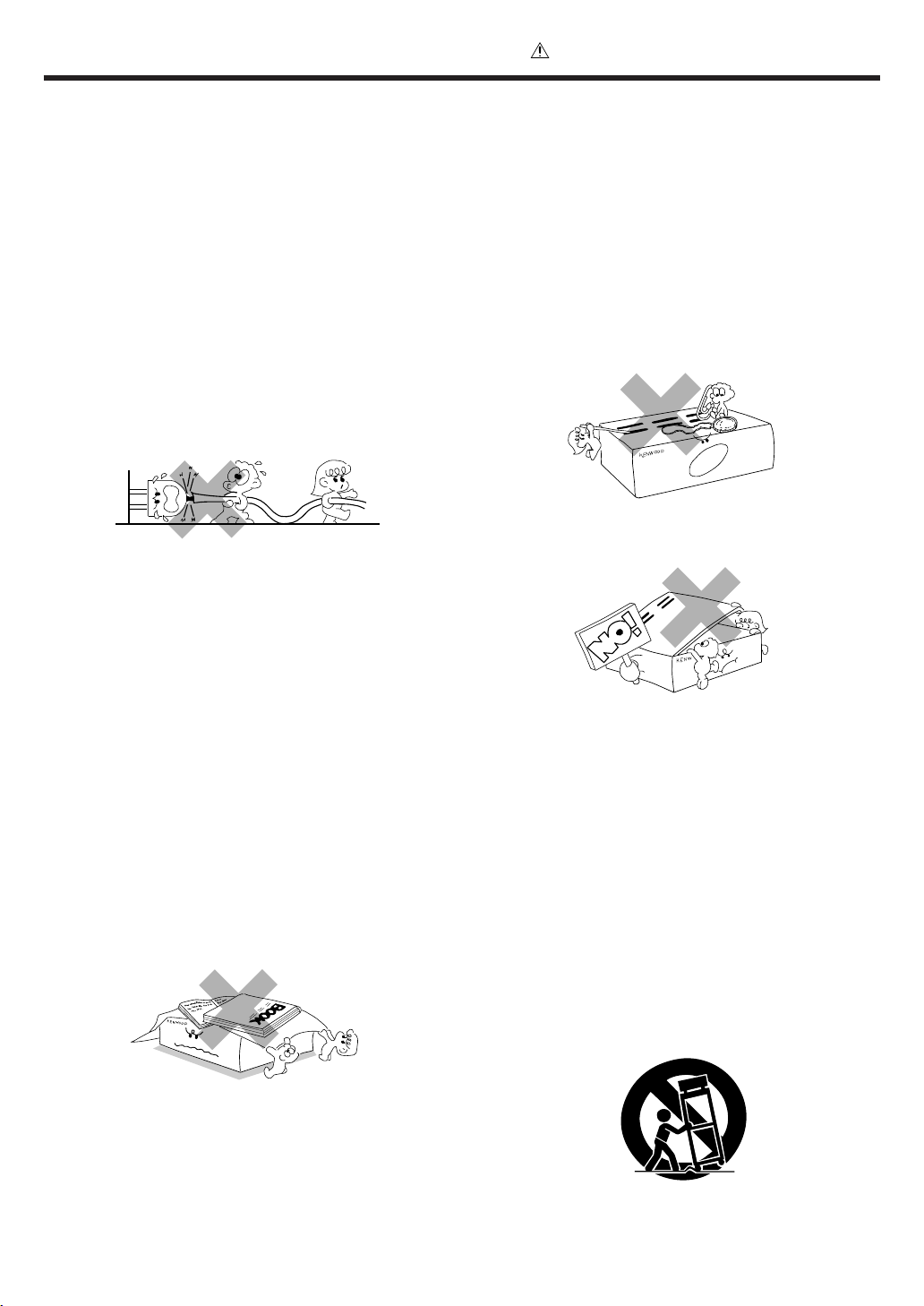
To maintain good ventilation, do not put records or a table-cloth
on the applia nce. Pla ce the appliance at least 10 cm away from
the walls.
Do not use the appliance on a bed, sofa, rug or similar surface
that may block the ventilation openings. This a ppliance should
not be placed in a built-in installation such as a bookcase or rack
unless proper v ent ilat ion is pr ovided or t he m anuf acturer ’ s
instructions have been adhered to.
5. Water and moisture – The a pplia nce shall not be exposed to
dripping and splashing - for example, near a ba thtub, washbowl,
kitche n sink, laundry tub, in a wet basement , or near a
swimming pool, etc. Do not place a n object containing liquid,
such as a flower vase, on the appliance.
Never pull or stretch
the cord.
Caution : Read this page carefully to ensure safe
operation.
Page 6
6
EN
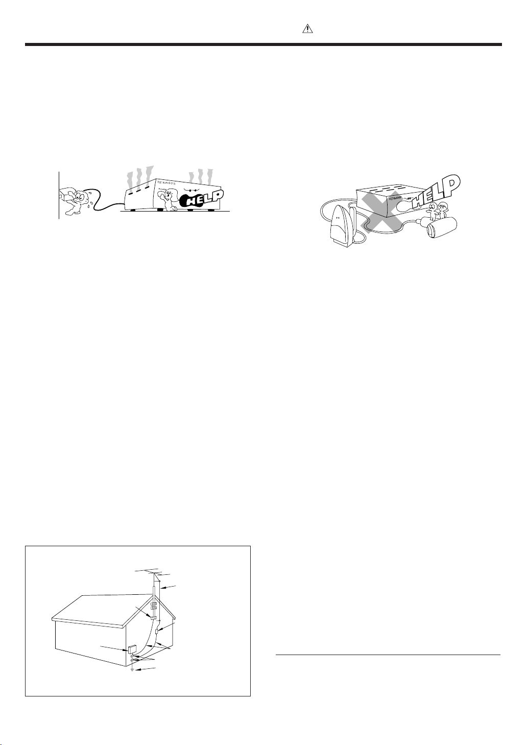
EXAMPLE OF ANTENNA GROUNDING AS PER NATIONAL
ELECTRICAL CODE
POWER SERVICE GROUNDING
ELECTRODE SYSTEM
(NEC ART 250, PART H)
NEC – NATIONAL ELECTRICAL CODE
GROUNDING CONDUCTORS
(NEC SECTION 810-21)
ANTENNA
LEAD IN WIRE
ANTENNA
DISCHARGE UNIT
(NEC SECTION 810-20)
GROUND CLAMP
ELECTRIC
SER VICE
EQUIPMENT
GROUND
CLAMPS
IM PORTANT SAFEGUARDS
Caution : Read this page carefully to ensure safe
operation.
13.Lightning – For added protect i on for this appliance during a
lightn i ng storm, or when it is left unattended and unused for
long periods of t ime, unplu g it f rom t he w all outlet and
disconnect t he ant enna or cable syste m . This w il l prevent
damage to t he appliance due to lightnin g and pow er-line
surges.
14.Abnormal smell – If an abnormal smell or sm oke is
detec te d, im m ediately tu rn t he powe r OFF and unplug
the appliance fr om the wall outlet. Cont act your dealer or
nearest service cent er.
15.Damage requiring service – The appliance should be
serviced by qualif ied serv ice perso nnel wh en:
A. The power-supply cord or the plug has been damaged.
B. Obje cts h ave fallen, or liquid has been spille d int o
the appliance.
C. The appliance has been exposed t o rain or water.
D. The appliance does not appear to operate n orm ally
by following the instruction manual. Adjust only those controls
that are covered by t he in st ruct ion m anual as an imp roper
adjustm ent of o ther controls m ay result in damage and will
oft en require extens ive w ork by a qualified technic ian to
restore the appliance to its normal operation.
E. The appliance has been dropped, o r the enclosure
damaged.
F. The appliance exhibits a marked change in performance.
16.Servicing – The user should not attempt to service the
appliance beyond that described in t he instruct ion
manual. All other servicing should be referred to qualified
service personn el.
17.Outdoor antenna grounding – If an outside antenna is
connected to the appliance, be sure the antenna system
is grounded so as to provide s om e prot ect ion against
voltage surges and built up static charges. Article 810 of
the N ation al Electrical Code ANSI/NFPA 70, provide s
inform ation w it h respect to proper grounding of the
mast and supporting struct ur e, g rou nd ing of t h e le ad-in
w ire t o an anten na discharge unit, size of gro unding
conductors, location of antenna discharge unit,
connect ion t o groundin g electrodes, and requirement s
for t h e groundi ng elect ro de. See Figure.
18.Power lines – An out side antenna syst em should not be
located in the vicinity of overhead power lines or other electric
light or power circuits, or where it can fall into such power lines
or circuits. When installing an outside antenna system, extreme
care should be taken to keep from touching such power lines
or circuits as contact with them might be fatal.
19.AC outlet s – Do not c onnect o ther audio equipm ent
with a power cons umpt ion l arger t han t hat sp ecified t o
the AC out let on t he rear panel. Never conn ect ot her
electr ical appliances, such as an iron or toaster, to it to
prevent f ire or elect ric s hock.
20.Overloading – Do not overload wall outlets, extension cords,
or integral convenience receptacles as this can result in a risk
of fire or electric shock.
21.Attachment – Do not use attachments not recommended by
the appliance manufacturer as they may cause hazards.
22.Replacement parts – When replacement parts are required,
be sure t he s ervice technician has used replacem ent p arts
specified by the manufacturer or have the same characteristics
as the original parts. Unauthorized substitutions may result in
fire, electric shock, or other hazards.
23.Safety check – Upon completion of any service or repairs to
this appliance, ask the se rvice technician t o pe rform safe t y
checks to determine that the appliance is in proper operating
condition.
Notes:
1. Item 3 is not required except for grounded or polarized equipment.
2. Item 17 and 18 are not required except for units provided with antenna
terminals.
3. Item 17 complies with UL in the U.S.A.
Page 7
7
EN
Names and functions of parts
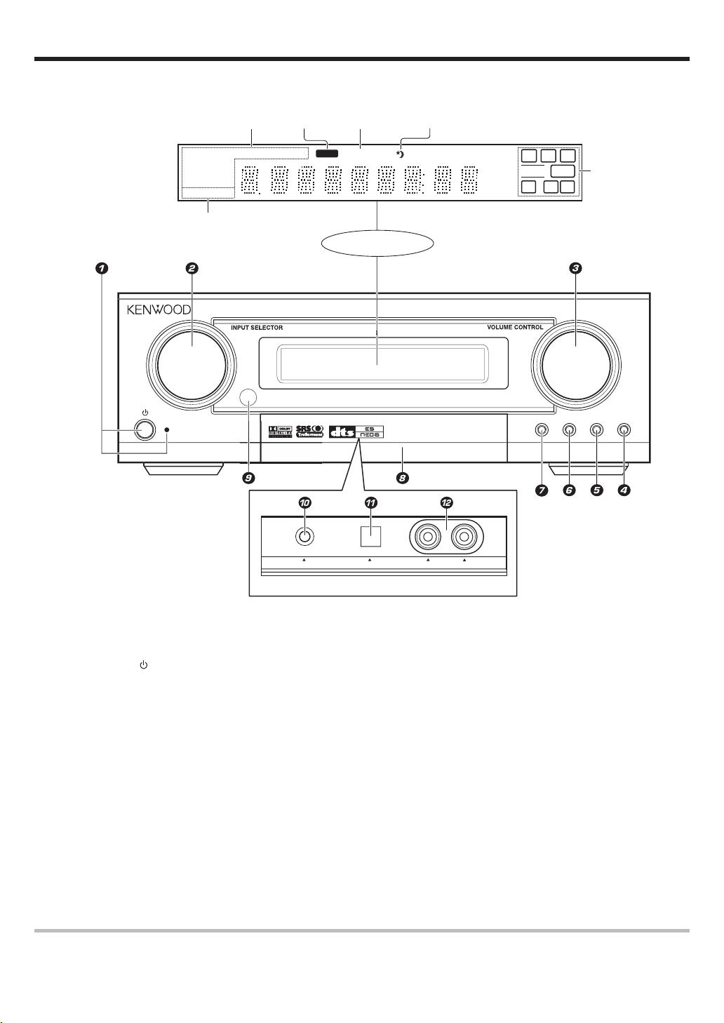
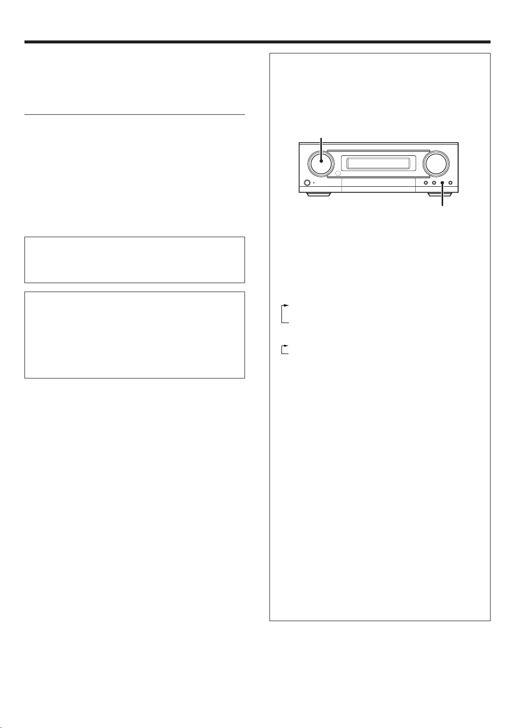
M ain unit
1
(POWER) key %
Use to turn the main power o n or o ff.
STANDBY indicator
Lights w hen stand by mode.
2 INPUT SELECTOR knob *
(DVD/ CD, VIDEO 1, VIDEO 2, FRONT AUX)
Use to s e le c t input sources.
3 VOLUME CONTROL knob *
4 ACTIVE EQ key (
Use to s e le ct ACTIVE EQ’s set ting.
5 INPUT MODE key 9
Use to s w itch between t h e full auto, dig ital
and analog inputs.
6 LISTEN MODE key £
Use to s e le ct t h e lis tening mode.
Standby mode
While the standby indicator is lit, a small amount of power is supplied to the system to back up the memory. This is called standby mode. Under the condition,
the system can be turned ON by remote control unit.
LISTEN MOD
E
INPUT MODE
A
C
TIVE EQ.
S
TERE
O
S
TAND B
Y
MUTEDOLBY DEX NEO:6 DSP TS DIGITAL RDS PTY ST. TUNED
FM/AM
AUTO
kHz
MHz
L
LFE SW
CR
DOLBY PLII
DTS -ES AAC
DISCRETE
MATRIX 6.1
ACTIVE EQ.
LS S BS RS
Display
DIGITAL
indicator
Listen Mode
indicators
MUTE
indicator
Sleep
indicator
Inside of FRONT AUX jacks' door
ACTIVE EQ.
indicator
Speaker selection
indicators
PHONES AUX OPTICAL L -AUDIO -R
DIGITAL SURROUND AMPLIFIER KAF-S500
AV CONTROL CENTE
R
PUSH OPE
N
7 STEREO key £
Use to s w itch the listen mode to STEREO.
8 Door for FRONT AUX jacks $(
When y o u us e FRONT AUX jacks, push right
side of this door and then pull t h e do o r to
open.
9 Remote sensor $
0 PHONES jack (
Use for h eadphone li stening.
! FRONT AUX (Digital in) jack
@ FRONT AUX (L-AUDIO-R) jacks $
Page 8
8
EN
Names and functions of parts
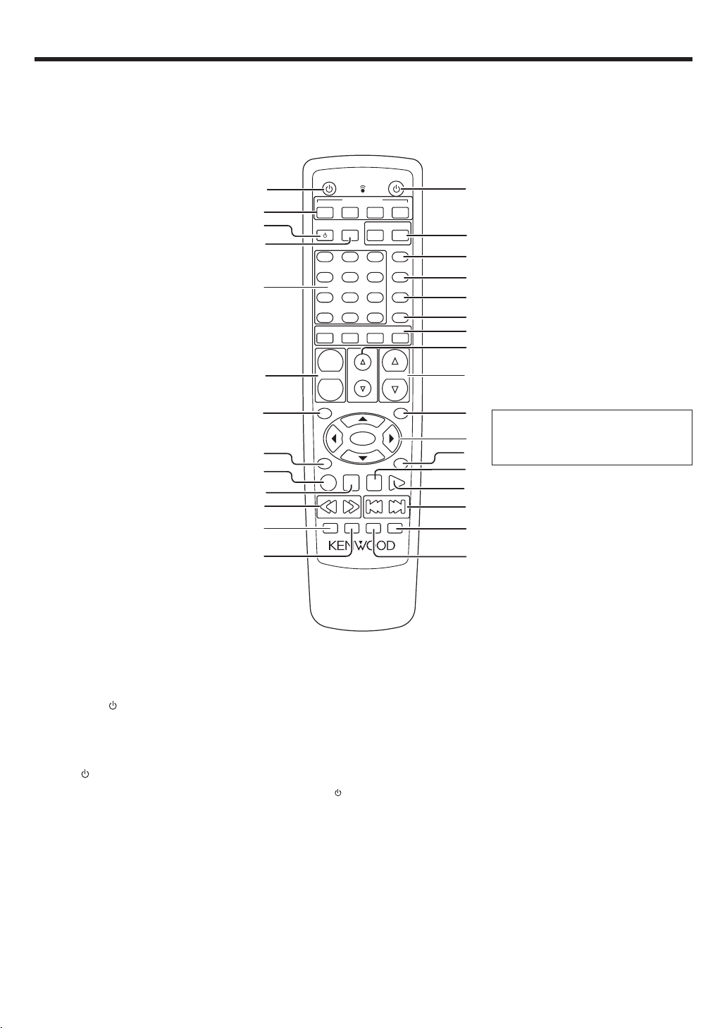
Remote control unit
This remote control unit can be used not only for Kenwood products but also for other non-Kenwood products by setting the appropriate manufacturer’s
setup c od e s . •
If the name of a function is different on
the receiver and on the remote control,
the name of the remote control key in
this manual is indicated in parentheses.
1 SOURCE
key §
Use to turn the othe r c omponents on or
off.
2
INPUT SELECTOR keys (DVD/CD, VIDEO 1,
VIDEO 2, FRONT AUX) *
Use to s el ect input sources.
3 TV key ¤
Use to turn the TV on or off.
4 TV INPUT key ¤
Use when in TV operation.
5 Numeric keys §
Provide funct ions ident ical t o t hose of t he
original remot e cont rol supplied w ith t he
compon e n t you are cont r ol lin g .
6 CHANNEL +/– keys ¤‹
Use to s e le ct t h e ch annels.
7 TOP MENU key ‹
Use to o p e rat e the DVD component.
8 RETURN key ‹
Use to o p e rat e the DVD component.
9 REC (÷) key ¤
This key functions as record key for oth e r
compon e nts.
0 STOP (7) key ¤‹
This key functions as the stop key for ot h er
compon e n ts.
¡ TRIM %/ fi keys %
Use to c o n trol a variety of settings.
™ VOLUME %/fi keys *
Use to adjust the r ec e iv er ’s volume.
£ M ENU key ‹
Use to o p e rat e o ther components.
¢ 5¥∞¥2¥3 keys ‹
Use to o p e rat e o ther components.
ENTER key §‹
Use to o p e rat e o ther components.
∞ ON SCREEN key §
Use to o p e rat e o ther components.
§ PAUSE (8) key ¤‹
This key functions as the pause key for
other co mponents.
¶ PLAY (3) key ¤‹
This key funct ions as th e play key for
other co mponents..
• 4 / ¢ keys ‹
These keys funct ion as skip keys f or
other co mponents.
ª M UTE key (
Use to temporary mute the so u nd .
º SLEEP key ∞
Use to s e tup sleep tim er .
! 1/ ¡ keys ¤‹
These keys function as search keys fo r
other co mponents.
@ STEREO key £
Use to w hich the listen mode to
STEREO.
# LISTEN MODE key £
Use to s e le ct t h e lis tening mode.
$ POWER
key %
Use to turn the amplifier on or off.
% TV VOLUME +/– keys ¤
Use to adjust the TV’s volume.
^ TV key ¤
Use when in TV operation.
& ACTIVE EQ. key (
Use to s e le ct ACTIVE EQ’s set ting.
* SOUND key (∞
Use to adjust t h e soun d qualit y and t he
ambience effects.
( SET UP key %
Use to select the speakers’ settings etc.
) SPEAKERS keys ∞
Use to s e le ct FRONT, CENTER, REAR,
and SW speakers.
8
0
5
2
9
6
3
-
+
7
4
1
+1
O
+1OO
STERE
O
SLEEP
MUTE
LISTEN MODE
STOP
PAUSE
PLAY
REC
ENTER
VOLUME
FRO
NT
CE
NTER
REAR
S
W
SET UP
SOUND
ACTIVE EQ.
SOURCE
+
-
CHANNEL
T
OP ME
NU
RETURN
MENU
ON SCREEN
TRI
M
TV INPUT
TV
TV
DVD/CD
INPUT SERECTOR
VIDEO 1
VIDEO 2
FRONT AUX
POWER
TV VOLUME
1
5
7
&
*
(
$
^
£
™
ª
¢
º
¶
§
¡
∞
8
3
9
0
#
@
•
)
2
6
!
4
%
Page 9
9
EN
Make connections as shown in the following pages.
When connecting the related system components, be sure
to refer t o the instruction manuals supplied wit h the
components you are connecting.
Do not connect the pow er cord to a wall outlet until all
connections are completed.
Note
Be su re t o insert all connecti on cord s secu rely. If their connections
are imperfect, sound may not be produced or there will be noise inference.
Analog connections
Audio connections are made using RCA pin cords. These cables transfer
stereo audio sign al in an “ analog” form. This means t he audio signal
corresponds to the act u al audio of two channels. These cables usually
have 2 plugs on each end, one red for the right channel and one white for
the lef t channel. These cables are usually packed toget her wit h t he
source unit, or are available at your local elect ro n ic s re tailer.
M icrocomputer malfunction
If operat ion is no t possib le or an erroneous display appears, even
though all connections have been m ade properly, reset the
microco mputer refer rin g to “ In case of d iffi cu lty” . ›
CAUTION
Be sure to adhere to the following, or proper ventilation will be
blocked causing damage or fire hazard.
• Do not place any objects impairing heat radiation onto the top of the
unit.
• Leave some space around the unit (from the largest outside dimension including pro je c tion) equal to or greate r than, shown below.
Top panel : 50 cm Side panel : 10 cm Back panel : 10 cm
Setting up the system
Input mode settings
DVD/ CD, VIDEO 2 and FRONT AUX in puts each include jacks fo r
digital audio input and analog audio input.
The initial factory settings for audio s ignal playbac k for DVD/CD,
VIDEO 2 and FRONT AUX.
After completing connections and turning on the amplifier, follow the
steps b el ow .
1 Use the Input Selector keys to select DVD/ CD, VIDEO 2 or
FRONT AUX.
2 Press the INPUT MODE key.
Each press switches the setting as follows:
In DVD/ CD, VIDEO 2 or FRONT AUX play mode
1 FULL AUTO (digital input, analog input)
2 D.MANUAL (digital input)
3 ANALOG (analog input )
In DTS play mode
1 FULL AUTO (digital input, analog input)
2 D.MANUAL (digital input)
Digital input:
Select t his set t ing t o play digit al signals from a DVD, CD, or LD
player.
Analog input:
Select this setting to play ana log signals from a cassette deck, VCR ,
or record player.
Auto detect:
In “ FULL AUTO” m ode (FULL AUTO displayed), the amplifier
detects t he dig ital or analog input signals automat ic ally. Priority is
given to digital signal during input mode selection. The receiver will
select t he in put m ode and listening m ode autom atically during
playback to match the type of input signal ( Dolby Digital, PCM, DTS)
and the speaker setting. The DIGITAL indicator on the display will
light up when digital signal is detected during FULL AUTO mode or
during D.MANUAL mode. If the input signal is analog, the DIGITAL
indicator will go off.
To keep the amp lifier set to the currently selected listening mode,
use the INPUT MODE key to select “ D.MANUAL” (manual sound) .
However, even when this setting is selected, there may be cases in
which the listening mode is selected automatically to match a Dolby
Digital source sig nal depending on t he com b ination of list ening
mode and source s ig n al.
At D.MAN UAL, if the audio reproduct i on stops in the middle due
to change in the input signals, etc. press the LISTEN MODE knob.
If t he IN PUT M ODE key is pressed quick ly, sound m ay not be
produced. Press t h e INPUT MODE key again.
INPUT SELECTOR
INPUT MODE
Page 10
10
EN
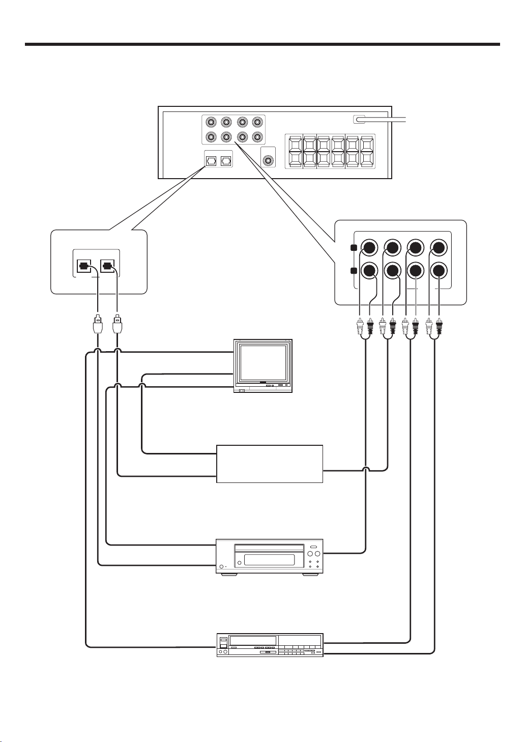
Connecting audio components
Setting up the system
OPT 1 OPT 2
OUT
DVD/CD IN- VIDEO 2 IN VIDEO 1
L
R
L
To AC wall outle
t
OUT
IN
OUT
Video output
(Yellow RCA pin cords)
Video input
(Yellow RCA pin cords)
Audio inputs and outputs
DVD player (e.g. DVF-S500)
or CDplayer
Satellite or component
with DTS, Dolby Digital,
or PCM DIGITAL OUT
Monitor TV
Audio
outputs
VIDEO IN 1
VIDEO IN 2
VIDEO IN 3
OPTICAL DIGITAL OUT
(AUDIO)
OUT
OUT
Optical fiber cable
Audio
outputs
OPTICAL DIGITAL OUT
(AUDIO)
Video deck
OUT
Video output
Optical fiber cable
OUT
Video output
Page 11

11
EN
Connecting the speakers ( for HTB-S500 system)
Connect terminals of same color between rear panel and speakers.
Also use speaker cord whic h have same co lo r ed tube as terminal.
White lined wire is for + polarity.
Setting up the system
Right Left
Right Left
Use this terminal if you
wish to connect to a
Back Surround speaker
with the SETUP of "6CH BS".
SUB/W
BS
L
R
L
R
REARCENTER FRONT
To AC wall outlet
Front Speakers
Surround Speakers
Center Speaker
Subwoofer or
Back Surround Speaker
KENWOOD
KENWOOD KENWOOD
KENWOOD KENWOOD
KENWOOD
Supplied speaker seals
Front speakers and surround speakers have screw holes to fix to
speaker stand. If yo u d on ’t u s e these holes , s tick supplied s e als
to hide ho le s .
Supplied speaker cushions
Stick th e su pplie d four cushion s to t he b ottom of the speakers.
(except subw oof er) It is ef fect ive f or slip-proof and deaden
vibrations of placed speakers.
Page 12
12
EN
Setting up the system
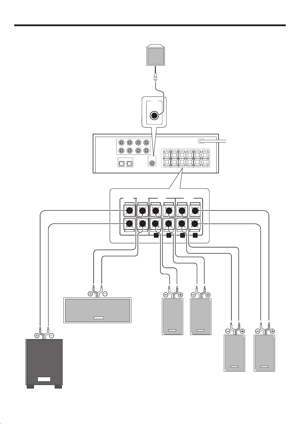
Connecting the speakers ( for KAF-S500 )
SUB/W
BS
L
R
L
R
REARCENTER FRONT
SUB
WOOFER
Right Left
Right Left
Recommend to connect Subwoofer to this terminal but
if you wish to connect to a Back Surround speaker
with the SETUP of "6CH BS", use this terminal.
To AC wall outlet
Front Speakers
Surround Speakers
Center Speaker
Subwoofer or Back Surround Speaker(option)
Powered subwoofer
When you connect Back Surround speaker to
SUB/W BS terminal, connect Powered
Subwoofer to this terminal.
KENWOOD
KENWOOD KENWOOD
KENWOOD KENWOOD
KENWOOD
Page 13

13
EN
Setting up the system
Connecting the terminals
1 Strip coating. 2 Push the lever.
3 Insert the cord. 4 Release the lever.
• Never short circuit the + and – speaker cords.
• If the left and right speakers are connected inversely or the speaker
cords are connect ed w it h reverse d polarity, t he sound w ill be
unnatural with ambiguous acoustic imaging. Be sure to connect the
speakers correctl y.
Speaker impedance
After confirming the speaker impedance indications printed on the
rear panel of the am plifier, connect speakers w ith m atching
impedance ratings. Using speakers with a rated impedance other
than that indicated on the rear panel of the amplifi er could result
in malfu n ctions or dam age to the s p eakers or re ce iv e r.
Speaker placement
Front (left and right) speakers
Place a t the front left and right of the listening position. Front speakers
are required for all surround modes.
Center speaker
Place front and center. This speaker stabilizes the sound image and
helps recreate so un d motion. Required for s u rr ou n d p layback.
Surround (left and right) speakers
Place at t he direct lef t and right , or slight ly behind , the list ening
position at even heights, approximately 1 meter above the ears of the
listener s. These speakers recreat e so und mot ion and atm o spher e.
Required for surr ou n d pl ayback.
Subwoofer
Reproduces powerful deep bass sounds.
Back surround speaker (option)
Place the speaker directly at t h e rear of the list enin g posi t ion . The
optimum p o si tion depends mainly on t he r o om condition.
• Altho ugh t he i deal surround syst e m consi st s of all t he speakers
listed above, if you don't have a center speaker or a subwoofer, you
can divide those s ignals betwee n th e available speakers in t he
speaker sett ings steps t o obtain t he best poss ible surround
reproduction from t h e sp e akers you h ave available. %
Center speaker
Subwoofer
Front speakers
(L,R)
Surround
speakers
(L,R)
Listening
position
Back surround
speaker
(option)
KENWOOD
KENWOOD
KENWOOD
Page 14

14
EN
PHONE
S
AUX
OPTICAL
T
AUDIO -R
L -AUDIO -R
Setting up the system
Connecting to the FRONT AUX jacks
The FR ONT AUX jacks a re convenient for connection of video components
such as a camcorder or a video game.
• To select the source connected to the FRONT AUX jacks select
FRONT AUX key. *
Camcorder, other
VCR, video game or
portable MD player
AUDIO
OUT
Preparing the remote control
Loading the batteries
1 Remove the cover. 2 Insert the batteries.
3 Close the cover.
• Insert tw o A AA-size (R03) batt eries as indicated by t he polarity
markings.
Operation
When the STANDBY indicator is lit, the power turns ON w hen you press
the POWER
key on the remote control. When the power comes ON,
press th e k ey y o u w ant to operat e .
• When pressing more than one remote control key successively, press
the keys securely by leaving an interval of 1 second or more between
keys.
Notes
1. The supplied batterie s may have shorter lives than ordinary batteries
due to u s e d ur in g op e rat i on checks.
2. When t he rem o te-cont rollable dist ance get s short er t han befor e,
replace both batte ri es w ith new ones.
3. Placing t he remot e se ns or i n d irec t sunlight, or in direct light from a
high fre qu e n cy fluorescent lamp may cause malfunct io n .
In such a case, c ha nge the location of the system installation to prevent
malfunction.
POWER
6 m
Infrared ray system
Operating range
(Approx.)
Remote senso
r
DIGITAL
OUT
Optical f ib e r
cable
Page 15

15
EN
Preparing for surround sound
Speaker settings
To enable you to obtain optimum enjoyment from the amplifier’s listening mod es, make sure to com pl et e the speaker set t ing s (subwoof er,
front, center, surround and surround back speakers) as described below.
If you p ur ch ase HTB-S500 system, you may skip step 2 t o 4 .
Original settings of this amplifier are adjusted to KSW-S500
speakers.
The original settin g s are
6ch AMP : 6ch SW Subwoo fer : SW ON
Front : FRONT NML Center : CNTR NML
Sorround : SURR NML Back surround : BS NML
Subwoo fer Re-Mix : REMIX ON
1
Turn on the pow er to this amplifier by pressing the
(POWER) key.
2
Press the SET UP key to enter the SET UP mode.
Use the TRIM%/ fi keys to select the “SP SETUP”
1 SP SETUP
2 TEST TONE
3 DISTANCE
4 DIMMER
5 EXIT
3
Press the SETUP key to select the 6ch AM P setti ng.
The Back Surround and Subwoofer o utput select io n s are displayed
as follows:
1 6ch SW : SUB/W B S speaker t erminal w ill output
Subwoo fer sound.
2 6ch BS : SUB/W BS speaker terminal will output Back
Surround sound. Subwoofer pre out will have
output fr om SW only .
3 6ch OFF : It is not advisable to use SUB/W BS speaker
terminal for this selection.
Use the TRIM%/fi keys to select the speakers.
Press the SETUP key to p ro c ee d to the next SETUP selection.
The flow o f the SETUP is as follows:
4
Select a speaker system.
If you h ave THX certified speakers, please set them to NML.
1 Press the SETUP key again so that t he subw oofer sett ing
indication “SW ON” appears.
2 Use the TRIM%/ fi keys to select the appropriate subwoofer
setting.
1 SW ON : Subwoofer setting mode to the amplifier is
ON.
2 SW OFF : Subwoofer setting mode to the amplifier is
OFF.
• When the setting “ SW OFF” is selected using the SET UP key,
the front speakers are a utomatically set to “ FR ONT LR G ” and the
procedure skips to step 6.
Before step 6, press the SET UP key to accept the setting.
3 Press the SET UP key to accept the setting.
• The front speakers setting indicatio n “ FRONT” appears.
4 Use the TRIM%/ fi keys to selec t the appropriate front speak-
ers setting.
1 FRONT LRG : Large front speakers are connected
to the amplifier.
2 FRONT NML : Average size front speakers are
connect e d to t h e am p li fier.
• For “ FRONT LRG” and “ SW ON” select ion, no s oun d will be
heard from subw oof er speaker even w hen it is set to on.
However, if you select “ RE MIX ON” in step @ when subwoofer
is selected, you will be able to hear sound from the subwoofer.
5 Press the SET UP key to accept the setting.
• The center sp e aker setting i nd ic at io n “ CNTR” appears.
Continued to next page
(POWER)
POWER
SET UP
TRIM%¥fi
SP SETUP TEST TONE DISTANCE DIMMER EXIT
6ch AMP setting
Subwoofer
MANUALAUTO
L
C
R
RS
LS
BS
SW
L R
Dimmer
C
SW
LS RS
BS
Front
Front
Center
Center
Surround
Surround
Back
Surround
Back
Surround
Subwoofer
Re-mix
Subwoofer
MUTEDOLBY DEX NEO:6 DSP TS DIGITAL ST.
AUTO
L
LFE
SW
CR
DOLBY PLII
DTS -ES AAC
DISCRETE
MATRIX 6.1
ACTIVE EQ.
LS S BS RS
MUTEDOLBY DEX NEO:6 DSP TS DIGITAL ST.
AUTO
L
LFE SW
C
R
DOLBY PLII
DTS -ES AAC
DISCRETE
MATRIX 6.1
ACTIVE EQ.
LS S BS RS
Page 16

16
EN
! Press the SET UP key again to accept t he setting.
• The subwoofe r r e mix setting in di cat i on ” REMIX” appears.
• If subwoofer is turned off, subwoofer re-mix setting is not visible.
@ Use the TRIM%/ fi keys to select the appropriate subwoofer
re-mix setting.
1 REMIX ON : Subwoof er re-m ix sett ing m ode t o
the amp li fier is ON.
2 REMIX OFF : Subw oof er re-mix set t ing m ode t o
the amp li fier is OFF.
When “REMIX ON” is selected, bass sound of other channel
w ill be added into Subwoofer or bass sound of Subwoofer
w ill be added into ot her channel to increase deep bass
performance.
# Press the SET UP key again to return to the 2.
• The receiver enters the speaker volume level adjustment mode.
• In st eps 5 and 6 , indications appear only f or the select ed
channels of the speakers that re q ui re adjusting.
5
Adjust the speaker volume level.
From your usual list ening p osit ion, adjust t h e volume levels. The
volume le v el s from each speaker should be the s ame.
1 Press the SET UP key and then use the TRIM%/ fi keys to
select TEST TONE.
2 Press the SET UP key for the following displays:
The selec tion of AUTO or MANUAL is done by the TRIM%/ fi
keys.
1 AUTO
2 MANUAL
3 Press the SET UP key again to begin TEST TONE.
Use the TRIM%/ fi keys to adjust the volume level of the test
tone output from the speaker channel to be adjusted.
For AUTO selec tion, the first test tone is heard from the front left
speaker for 3 seconds. The next test tone is heard from the
speakers in the following sequence for 3 seconds each.
The channel indication blinks while the test tone is being output.
• If you change the volume level settings for the speakers while
listening to music, the settings referred to on this page are also
changed.
• If the speaker setting selects are OFF, the speaker level settings
are reset.
For “MANUAL” selection, press the FRONT, CENTER, REAR
or SW keys to select the speaker channel and then adjust the
volume level by pressing TRIM%/ fi keys.
Preparing for surround sound
6 Use the TRIM% / fi keys to select the appropriat e center
speaker setting.
If you selected “LRG” as the front speakers setting,
1 CNTR NML : An average size center speaker is
connect e d to t h e am p li fier.
2 CNTR LRG : A large center speaker is connected
to the amplifier.
3 CNTR OFF : Center spe aker setting mode to the
amplifie r is O FF.
If you selected “NML” as the front speakers setting,
1 CNTR ON : Center speaker set ting mode to the
receiver is ON.
2 CNTR OFF : Center speaker setting mode to the
receiver is OFF.
7 Press the SET UP key again to accept t he setting.
• The surround speaker indication “ SURR” appears.
8 Use the TRIM% / fi keys to select the appropriate surround
speaker setting.
If you selected “LRG” as the center speaker setting,
1 SURR NML : Average size surround speakers are
connect e d to t h e am p li fier.
2 SURR LRG : Large surround speakers are
connect e d to t h e am p li fier.
3 SURR OFF : Surround speaker sett ing m ode t o
the amp li fier is OFF.
If you selec ted other than “LRG” as the center speaker setting,
1 SURR ON : Surround speaker setting mode to the
amplifie r is O N .
2 SURR OFF : Surround speaker setting mo d e to t h e
amplifie r is O FF.
• When the setting “ SUR R OF F ” is selected, by pressing the SET
UP key in step 9 t he p roce dur e ski ps to st ep @. Bu t if “ SW
OFF” is selected, press the SET UP key to skip to step 5.
9 Press the SET UP key again to accept t he setting.
• The back surround speaker setting indicatio n “ BS” appears.
0 Use the TRIM%/ fi keys to select appropriate surround back
speaker setting.
If you selected “LRG” as the surround speaker setting,
1 BS NML : Average size back surround speaker is
connect e d to t h e am p li fier.
2 BS LRG : Large back surround speaker is con-
nected to t h e amplifier.
3 BS OFF : Back surround speaker setting mode to
the amp li fier is OFF.
If you selected “NML” as the surround speaker setting,
1 BS NML : Back surround speaker setting mode
to the amplifier is ON.
2 BS OFF : Back surround speaker setting mode
to the amplifier is OFF.
MUTEDOLBY DEX NEO:6 DSP TS DIGITAL ST.
AUTO
L
LFE SW
CR
DOLBY PLII
DTS -ES AAC
DISCRETE
MATRIX 6.1
ACTIVE EQ.
LS S BS RS
LC RRS
BSLSSW
MUTEDOLBY DEX NEO:6 DSP TS DIGITAL ST.
AUTO
L
LFE SW
CR
DOLBY PLII
DTS -ES AAC
DISCRETE
MATRIX 6.1
ACTIVE EQ.
LS S BS RS
MUTEDOLBY DEX NEO:6 DSP TS DIGITAL ST.
AUTO
L
LFE SW
CR
DOLBY PLII
DTS -ES AAC
DISCRETE
MATRIX 6.1
ACTIVE EQ.
LS S BS RS
Page 17

17
EN
• Press the FRONT key each time to s e le c t Front L or Front R
channel.
• Press the CENTER or SW k ey to select cent e r o r s u bw oofer
channel.
• Press the REAR key t o s el ec t surround c hannel.
And use the REAR key for the foll ow ing displays.
1 LS : Surround L channel.
2 BS : Back surround channel.
3 RS : Surround R channel.
4 Press the SET UP key again.
• The test tone is turned off and return to the main setup displays.
6
Input the distance to the speakers.
1 Measure the distance from the listening position to each of
the speakers.
Jot down the distance to each of the speakers.
Distance t o Front left s peaker (L) : ____ meters
Distance t o Cent e r sp eaker (C) : ____ meters
Distance t o Front right speaker (R) : ____ meters
Distance t o Surround r ight (RS) : ____ meters
Distance t o Back Surround (BS) : ____ meters
Distance t o Surround l eft (LS) : ____ mete rs
Distance t o Subwoofer (SW) : ____ meters
2 Press theTRIM%/ fi keys to select the “DISTANCE ” on setup
displays and press the SETUP key again.
3 Use the SET UP key to select the speakers and the TRIM%/ fi
keys to adjust the distance to the front speakers.
The speaker indicator to b e adjusted blinks.
• The allowable setting range is 0.3 to 9.0 m, adjustable in 0.3 m
increments.
4 Repeat steps 3 to input the distance for each of the speakers .
5 Press the SET UP key again to return to main setup displays.
• The speakers you have selected s hould appear on the display.
Confirm that all the s p e akers have been corre c tly selected.
Preparing for surround sound
MUTEDOLBY DEX NEO:6 DSP TS DIGITAL ST.
AUTO
L
LFE SW
C
R
DOLBY PLII
DTS -ES AAC
DISCRETE
MATRIX 6.1
ACTIVE EQ.
LS S BS RS
Page 18

18
EN
Preparing for playback
Some preparatory steps are needed before starti ng pl ayback.
Turning on the amplifier
1 Turn on the power to the related components.
2 Turn on the power to this amplifier by pressing the
(POWER) key.
Selecting the input mode
If you have selected a component connected to the DVD/ CD, VIDEO 2
or FRONT AUX jacks, make sure that the input mode setting is correct
for the ty p e of audio signal to be u se d . 9
Normal playback
Listening to a source component
1
Use the INPUT SELECTOR knob (or INPUT SELECTOR keys)
and AV AUX key to select the source you want to listen to.
Selecting a source using each key.
1 “DVD/CD”
2 “VIDEO 1”
3 “VIDEO 2“
4 “FRONT AUX”
2
Start playback from the selected source.
3
Use the VOLUM E CONTROL knob (or VOLUM E CONTROL
%¥fi keys) to adjust the volume.
(POWER)
INPUT MODE
POWER
VOLUME CONTROLINPUT SELECTOR
INPUT SELECTOR
VOLUME%¥fi
Page 19

19
EN
Normal playback
Adjusting the sound
Adjusting the TONE
You can a djust the sound quality when the receiver is in the PCM stereo
mode, analog ste re o mode.
1 Press the SOUND key to select the SOUND mode.
When input signal is Dolby Digital and STEREO
1 T.SURR ON or OFF : SRS TruSurround
2 TONE : Tone
3 NIGHT ON or OFF : M id n ig h t m o d e
When input signal is except STEREO
TONE : Tone
• For other in pu t signal, som e o f mode will not be displayed.
2 Use the TRIM%/ fi keys to select TONE and then press SOUND
key.
3 When in TONE ON selection, press the SOU ND key for t he
following displays.
BASS : Select this to adjust the lo w frequency r ange.
TREBLE: Select this to adjust the high frequency range.
4 Use the TRIM%/ fi keys to adjust the sound quality.
• The bass and treble levels are adjustable from -10 to +10 in 2 step
increments.
• The adjustmen t ite m is displayed for approximately 2 0 s e co n ds .
VOLUME CONTRO
L
PHONES
VOLUME%¥fi
ACTIVE EQ
SOUND
POWER
TRIM%¥fi
ACTIVE EQ.
MUTE
MUTEDOLBY DEX NEO:6 DSP TS DIGITAL ST.
AUTO
L
LFE SW
CR
DOLBY PLII
DTS -ES AAC
DISCRETE
MATRIX 6.1
ACTIVE EQ.
LS SBS RS
MUTEDOLBY DEX NEO:6 DSP TS DIGITAL ST.
AUTO
L
LFE SW
CR
DOLBY PLII
DTS -ES AAC
DISCRETE
MATRIX 6.1
ACTIVE EQ.
LS SBS RS
MUTEDOLBY DEX NEO:6 DSP TS DIGITAL
DOLBY PLII
DTS -ES AAC
DISCRETE
MATRIX 6.1
ACTIVE EQ.
PHONES
M uting the sound
The MUTE key lets you mute the so un d o f t he s p eakers.
Press the MUTE key.
Blinks
To canc el
Press the MUTE key again so that the “MUTE” indicator goes off.
• MUTE ON can also be deactivat e d b y turning the pressing
VOLUME CONTROL knob (or VOLUME %/fi keys).
ACTIVE EQ mode
You can enjoy a more impr essive sound ef fec t wh en ACTIVE EQ is
turned ON during Dolby Digital and DTS pla yba ck a nd, when in PCM and
analog stereo mo de .
Press the ACTIVE EQ key for the following selections;
1EQ CINEMA :Effective when watching a movie.
(The ACTIVE EQ. indicator light s up . )
2EQ MUSIC :Effective when listening to music.
(The ACTIVE EQ. indicator light s up . )
3EQ OFF :The ACTIVE EQ function is turned OFF.
(The ACTIVE EQ. indicator goes off.)
• ACTIVE EQ funct io n w ill not be available whe n d u rin g re c o rd in g
or DTS-ES MATRIX is ON, and during 96kHz LPCM playback.
Listening with headphones
1 Connect headphones to the PHONES jack.
• Headphones with a stereo min i pl ug c an be conn ec ted.
• The sounds from all speakers are cut off.
2 Use the VOLUME CONTROL knob (or VOLUME%/ fi keys) to
adjust the volume.
Page 20

20
EN
Recording audio (analog sources)
Recording a music source
1 Use the INPUT SELECTOR knob (or INPUT SELECTOR keys) to
select the source (other than “VIDEO 1”) you want to record.
• Connect analogue audio outp uts to this Amplifier. 0
2 Start playback, then start recording.
Recording
INPUT SELECTOR
INPUT SELECTOR
Page 21

21
EN
This receiver is equipped wit h listening modes that allow
you to enjoy an enhanced sonic ambience with a variety of
video sources.
In order to obt ain t he opt im um effect from t he surround
modes, make sure to input the proper speaker settings
beforehand. %
Surround modes
Dolby Digital
The Dolby Digital surround format lets y o u e n jo y u p to 5.1 channels
of digital surround sound from Dolby Digital program sources (such as
Laserdisc or DVD software marked
). C ompared with previous Dolby surround, Dolby Digital provides even better sound quality,
greater spatial accuracy, and improved dynami c range.
Although a full set of speakers (front left, right, and center, surround
left and right, and a subwoofer) is required for true 5.1 channel Dolby
Digital surround sound, this receiver lets you enjoy Dolby Digital (and
Dolby Surround) program sources, even if you connect only the front
speakers.
Manufactured under license from Dolby Laboratories. “ Dolby” , “ Pro
Logic” , “ Surround EX” and the do ubl e-D symbol are trademarks of
Dolby Laboratories.
Ambience effects
Note
*LFE = Low Frequency Effects. This channel delivers separate nondirectional bass signa ls to the subwoofer for more dynamic deep bass
sound ef fects.
DTS
The DTS multi-channel audio format is available on CD, LD and DVD
software. DTS is strictly digital format and cannot be decoded inside
most CD, LD or DVD players. For this reason. If you attempt to listen
to DTS encoded software through the analog output of your new CD,
LD or DVD player, you will experience digital noise in most cases. This
noise can be quite loud if the analog output is connected directly to a
high power amplification system . Proper measures for pl aying t he
digital out put as described below should b e taken t o avoid this
situation . To enjoy DTS Digital Surround playback, an external 5.1
channel DTS Digital Surround decoder system or an amplifier with a
built-in DTS Digital Surround decoder must be connected to the digital
output (S/P DIF, AES/EBU or TosLink) of a CD, LD or DVD player.
All mod e ls are incorpo rat e d w i th t h e D TS decoder.
Note
*LFE = Low Frequency Effects. This channel delivers separate nondirectional bass signa ls to the subwoofer for more dynamic deep bass
sound ef fects.
DTS has a .1 or LFE channel.
The indication “ LFE” appears in t he dis play when a signal is being
input for t h is c h annel.
Dolby PRO LOGIC II
Dolby Pro Logic II was designed specifically to provide a new sense
of spatialit y, direct ionality and articulati on of sounds f rom Dolby
Surround encoded sources (such as video and Laserdisc software
marked
). T his is a chieved with an intelligent, built-in
feedback logic design, a matrix surround decoding and the decoding
of stereo, full bandwidth surround outputs. The PRO LOGIC
II modes
programm ed i nt o t hi s recei ver are “ MOVIE”, “ MUSIC” and “PRO
LOGIC” . The “ M OVIE” mode of t he PRO LOGIC
II has preset
characteristics to produce a calibrated.
Center speaker
Subwoofer
(SW)*
Front speakers
(L,R)
Surround
speakers
(L,R)
KENWOOD
KENWOOD
KENWOOD
*Optional in this mode.
Center speaker
Subwoofer
(SW)*
Front speakers
(L,R)
Surround
speakers
(L,R)
KENWOOD
KENWOOD
KENWOOD
*Optional in this mode.
Center speaker
Subwoofer
(SW)
Front speakers
(L,R)
Surround
speakers
(L,R)
KENWOOD
KENWOOD
KENWOOD
“ DTS” , “ DTS-ES Extended Surround” and “ Neo:6” are trademarks
of Digital Theater Systems, Inc.
Page 22

22
EN
Dolby Digital EX
Dolby Digit al EX is an extension of D olby Digital technolo gy, D olby
Digital EX creates six full-bandwidth output channels from 6.1-channel sources. This is done u sing a m atri x de cod er that derives three
surround channels from the t w o i n the original recording.
This is achieved by using th ree diff erent surround sign als, Left
Surround , Right Surround, and Back Surround, each driving its ow n
array of speakers. Think of it as adding a cent e r c h annel for th e rear
speakers, which give more diffuse and natural surround effect, even
if you w ant ed t h e ability t o complet ely en circle t h e audience wit h
sound, positioning sound effects exactly where they wolud be heard
in real life. For best results, Dolby Di git al EX should be used w i t h
movie s ound tracks recorded wit h Dol by D igital Surround EX which
contain a digital fl ag that w ill autom atically activate t his f eature.
However, for titles released prior to late 2001, this feature has to be
activated manually.
Although a full set of speakers (front left and right, center, surround
left and right, back surround and a subwoofer) are required for true 6.1
channel Dolby Digital surround EX sound, this receiver lets you enjoy
Dolby Digit al (and Dolby Surround) program so urces, even if y ou
connect o n ly the front spe akers.
Although only Dolby Digital soundtracks incorporate a separa te low
frequency channel, connecting a subwoofer will also improve deep
bass performance in the other surroun d modes.
The indication “LFE” appears in the display when a signal is being
input for t h is c h annel.
DTS-ES
DTS-ES (Digital Theater System -Extended Surround) present s 6.1
channels surround syst em wit h addit ional Back Surround channe
l
which evolved from the conventional 5.1 channels surround system
.
DTS- E S format that was recorded in DVD, CD or LD comprises of two
modes. DTS-ES Discrete 6.1 produ ce t he discr et e back surround
w h ich i s completely independent and DTS-ES Matrix 6.1 pro duce s
the back surround which synthesised within the left and right surround
channels using matrix technology. DTS-ES has perfect compatibility
w i th the con ven tional 5.1 channels surround system . 6.1 channels
surround with an additional back surround present s a m o re n atura
l
presence and surround effe c ts by increasing the impression of the
sound image from back. Progra ms which are recorded using DTS-E S
technology consist of information flags which will be able to contro
l
the Disc r ete and Matrix mode. Thus, it can automatically select the
best matched mode.
Neo:6
Neo:6 is a new t echno logy which was develop ed by DTS. It can
produce high grade 6 channels surround with an astonishing fidelity
from 2 channels content. Ne o:6 has 2 mode, "CINEMA" mode is for
movie p layback and "MUSIC" mod e is for music playback.
DTS has a .1 or LFE channel.
The indication “LFE” appears in the display when a signal is being
input for t h is c h annel.
Ambience effects
DSP mode
The DSP mode lets you add the atmosphere of a live concert or hall
to almost any type of program source. These modes are particularly
effective when used with stereo program sources, like CD, television,
and FM radio. You might enjoy t rying t he ARENA, JAZZ CLUB,
THEATER, STADIUM or DISCO mode t he ne xt t im e you watch a
concert o r s p o rting event!
What' s DSP?
DSP stands for Digital Signal Processor.
The way a sound is heard in an actual environm ent dep ends on a
variety of different factors. One of the most important is reverberation
(the act of decaying elemen ts of sound echoing in various places).
The DSP modes produce the feeling of presence by using the DSP to
create reverberation, without spoiling the sound quality of the original
signal.
Center speaker
Subwoofer
(SW)
Front speakers
(L,R)
Surround
speakers
(L,R)
KENWOOD
KENWOOD
KENWOOD
Center speaker
Subwoofer
(SW)*
Front speakers
(L,R)
Surround
speakers
(L,R)
Back surround
speaker
KENWOOD
KENWOOD
KENWOOD
*Optional in this mode.
Center speaker
Subwoofer
(SW)*
Front speakers
(L,R)
Surround
speakers
(L,R)
Back surround
speaker
KENWOOD
KENWOOD
KENWOOD
*Optional in this mode.
Page 23

23
EN
Surround play
The DTS compatible models can reproduce a CD, DVD, or LD carrying the
DTS mark.
DOLBY DIGITAL ca n be used when playing DVD or LD software bearing
the
mark and DOLBY DIGIT AL format digital broadcasts (etc.).
DOLBY PRO LOGIC can be used w hen playing video, DVD, or LD
software bearing the
mark.
Preparations
• Turn ON related components.
• Complete “ Preparing for surround sou nd ” (speaker set tings). %
• Use the INPUT SELE C TOR knob (or INPUT SEL E CTOR keys) to select
the component you wish to play back wi th surround so u nd .
• Use the INPUT MODE key to select the input mode (analog or digital)
for the source you w ish to play back. 9
• Noise will be produced when a DTS source is played by selecting the
analog input.
1
Start playing the video softw are.
2
Use the LISTEN M ODE key to sel ect the listening mode.
The listening mode settings are stored separately f o r e ach input. If
the inpu t mode is set t o f u ll auto t he receiv er sele ct s t he optimal
listening mode automatically based on the type of input sig nal and
the spe aker settings .
Each press of the LISTEN M ODE key swit ches the setting as
listed below.
The listening mode settings are different depending on the type
of input signal.
Dolby Digital Surround EX compliant disc :
Dolby Digital Surround EX compliant disc contains the identification
signals. When yo u choose FULL AUTO during “ Input m ode set tings” (9), this am plif ire det e ct s the ident ification sign als and
change the LISTEN mode to the DOLBY D E X(Dolby Digital Surround
EX mode) auto matically.
But sometimes we find some discs which is Dolby Digital Surround
EX compliant disc but it doe s no t contain the identificatio n s ig n als.
If you f ind t he not ice like “ Surround EX” on the label of disc or
package, you can choose DOLBY D EX then yo u c an enjoy Dolb y
Digital Surround EX sound.
Ambience effects
Continued to next page
MUTEDOLBY D NEO:6 DSP TS DIGITAL ST.
AUTO
L
LFE SW
CR
DOLBY PLII
DTS -ES AAC
DISCRETE
MATRIX 6.1
ACTIVE EQ.
LS SBS RS
When the DOLBY DIGITAL EX or DOLBY DIGITAL signal is
input :
(The DOLBY D or DOLB Y PLII , indicator lights up.)
1 DOLBY D : DOLBY DIGITAL EX surround.
(The DOLBY D EX indicator lights up . )
When D OLBY DIGITAL signal is input or
Back surround speaker is OFF, this m enu
will not b e d is pl ayed.
2 DOLBY D : DOLBY DIGITAL surround.
(The DOLBY D indicator li gh ts up.)
3 MOVIE : PRO LOGIC II surround MOVIE mode.
(The DOLBY PLII in di cat o r lig h ts up.)
4 PRO LOGIC : PRO LOGIC II sur ro un d PRO LOGIC mode.
(The DOLBY PL indicator lights up.)
5 STEREO : Norm al stereo playback.Whe n you select
DOLBY DIGITAL
“ DOLBY D” w il l b e d is pl ayed.
When the DTS or DTS- ES (matrix or discrete) signal is input :
1 DTS : DTS 5.1ch surround mode.
(DTS indicator lights up.)
2 MTRX 6.1 : DTS 6.1ch MATRIX surround mode.
(DTS-ES and MATRIX 6.1 indicators light u p. )
3 DSCRT 6.1 : DTS 6.1ch DISCRETE surround mode.
(DTS - E S a nd DISC R E T E 6.1 indicators light up.)
4 STEREO : Normal stereo p layback.
When the analog signal or the digital signal (except for
DOLBY DIGITAL or DTS signal) is input :
1 MOVIE : PRO LOGIC II surround MOVIE mode.
(The DOLBY PL II indicator lights up.)
2 MUSIC : PRO LOGIC II surround MUSIC mode .
(The DOLBY PL indicator lights up.)
3 PRO LOGIC : PRO LOGIC II surroun d PRO LOGIC mode.
(The DOLBY PL indicator lights up.)
4 CINEMA : NEO:6 surround.
(The NEO:6 indicator ligh ts up.)
5 MUSIC : NEO:6 surround.
(The NEO:6 indicator ligh ts up.)
6 ARENA : DSP surround ARENA mode.
(The DSP indicator lights u p .)
7 JAZZ CLUB : DSP surround JAZZ CLUB mode.
(The DSP indicator lights u p .)
8 STADIUM : DSP surround STADIUM mod e .
(The DSP indicator lights u p .)
9 DISCO : DSP surround DISCO mode.
(The DSP indicator lights u p .)
0 THEATER : DSP surround THEATER mode.
(The DSP indicator lights u p .)
- STEREO : Normal stereo playback.
• Dolby Digital or DTS signal ha ving more channels than the maximum
number of playback channels available using the receiver’s current
settings is input, downmixing is performed to match the number of
available speaker channels.
• The DSP mode selection is displayed for approximately 3 seconds.
3
Adjust the volume.
INPUT SELECTOR
INPUT SELECTOR
STEREO
LISTEN MODE
INPUT MODE
STEREO
LISTEN MODE
Page 24

24
EN
Ambience effects
1
Select STEREO mode using LISTEN M ODE key. £
2
Press the SOUND key tw ice.
3
Use the TRIM %¥fi keys to select ON or OFF.
1 T.SURR ON : SRS TruSurround ON.
2 T.SURR OFF : SRS TruSurround OFF.
4
Press the SOUND key to return to the input indi cation.
• The adjustme nt it e m is displayed for approximately 2 0 s ec o n ds .
SRS TruSurround play
When STERE O mode has been chosen in LISTEN MODE a nd input signal
is STEREO, you can enjoy surro u n d eff ec t by SRS TruSurround.
LISTEN MODE
TRIM%¥fi
SOUND
LISTEN MODE
To charge to STEREO mode.
When you press the STER EO key, the LISTEN mode will be switched to
the STEREO mode.
During above STEREO mode, if yo u press STEREO key again, the
STEREO mo d e w ill be switche d back to the L ISTEN mode.
• If yo u sw itch t o the STEREO mode using STEREO key, the DSP
mode w ill be turned o ff automatically.
• If you turn off and on the POWER, setting of the LISTEN mode will
not be l oo s e d.
Notes
• Depending on the type of the signal or speaker setting, some listening
modes cannot be selected.
• When playback is started, the sound may be cut or interrupted before
the inpu t source is c o nfirmed as Dolby Digital.
Page 25

25
EN
Adjustment of each channel s’ level
You can adjust e ach channel’ s l ev e l d u n in g lis tening music.
1 Press the FRONT key to adjust FRONT L channel’s level.
2 Use the TRIM%/fi keys to adjust the sound level.
3 Press the FRONT key to adjust FRONT R channel’s level.
4 Use the TRIM%/fi keys to adjust the sound level.
5 Press the FRONT key to return to the input indication.
• The sound level is adjustable from -10 dB to + 10 dB in 1dB step
increme nts.
• The adjustmen t it em is displayed for approximately 2 0 s e co n ds .
• Use t he CENTER or SW key t o adjust sound lev el of center or
subwoof er c h annel.
• Use t h e REAR key to adjust sound le v el o f surround c hannel.
And use the REAR key for the follo w ing displays.
1 LS : Surround L channel.
2 BS : Surround back channel.
3 RS : Surround R channel.
Convenient functions
MUTEDOLBY DEX NEO:6 DSP TS DIGITAL ST.
AUTO
L
LFE SW
CR
DOLBY PLII
DTS -ES AAC
DISCRETE
MATRIX 6.1
ACTIVE EQ.
LS SBS RS
TRIM%¥fi
SWFRONT
REAR
SOUND
CENTER
M idnight mode (Dolby Di gital mode only)
When w atching mov ie s at n ig h t , you might n o t be able to r aise the volume as
loud as normal. Midnight mo de compresses the dynamic range of pre viously
specified heavy sound passage of the Dolby Digital sound track (like scenes with
sudden increases in volume) to minimize the difference in volume between the
scenes with heavy sound passage and scenes with normal sound passage. This
makes it easy to hear all of the sound track, even when listening at low volumes.
1 Press the SOUND key to enter the SOUND mode.
• This can be selected only if DVD/CD, VIDEO 2 or FRONT AUX is
selected as the source and the listen mode is set to “ DOLBY DIGIT AL.”
2 Use the TRIM%/ fi keys to select the “NIGHT” and then press
the SOUND key.
3 U se the TRIM%/ fi keys to select ON or OFF.
1 NIGHT ON : Midnight m o de O N .
2 NIGHT OFF : Midnight m od e O FF.
4 Press the SOUND key to returm to the input indication.
• The adjustmen t ite m is displayed for approximately 2 0 s e co n ds .
• Some Dolby Di gital soft w are may not be com patible w it h t he
Midnight mode.
Display dimmer adjustment
The dimm er funct ion le t s y ou sele ct the brightness of the amplif ie r's
display. You might f ind t his usef ul if you darken your roo m t o watc h
movies o r l is ten to music.
1 Press the SET UP key to enter the SETUP mode.
2 Use the TRIM%/fi keys to select the “DIMMER”.
3 Press the SET UP key again so that the dimmer setting indication
appears.
Select the bright ness level you find most pleasing using TRIM
(%/fi ) keys.
1 DIMMER H : Bright
2 DIMMER L : Dark
4 Press the SET UP key to return to the “DIMMER”.
5 Use the TRIM%/fi keys to select the “EXIT”.
6 Press the SET UP key to return to the input indication.
Sleep timer (SLEEP)
Set the nu mber of min utes after which the unit to be turned OFF.
Connect t he relat ed component under reference to “ Connecting
audio components”.
Press the SLEEP key to select t he time.
• Each press increases the timer pe rio d b y 1 0 minites.
The sleep timer can be setu p to 90 minites .
10 = 20 = 30 = .... = 80 = 90 = OFF = 10 = 20 = ....
The sleep timer indicator will b e lit.
• The sysytem has been setup so taht the display is dimmered automatically wh il e the sleep tim er is activated.
• Press the SLEEP key while t he sle ep tim er is act ivate d to check the
remaining time.
To cancel
Turn the amplifier OFF or press the SLEEP key until the sleep tim e is
caucelled.
96kHz LPCM playback
The amplifier is c ompatible with the 96kH z LPCM playback. To play a
96kHz DVD, set t he l is ten mode to “ STEREO” .
• In FULL AUTO input mod e the li sten m ode will automat ically be
STEREO.
• When in D MANUAL input mode (listen mode is not STER E O) , “96kHz
LPCM” will appear in the display and no sound can be heard from the
speakers.
Press the LISTEN MODE or STE REO key (the listen mode changes to
the STEREO mode) to o utput sound f ro m t h e s pe akers.
MUTEDOLBY DEX NEO:6 DSP TS DIGITAL ST.
AUTO
L
LFE SW
CR
DOLBY PLII
DTS -ES AAC
DISCRETE
MATRIX 6.1
ACTIVE EQ.
LS S BS RS
Page 26

26
EN
The remot e control supplied wit h this amplifier is also
capable of controlling component s from a variety of
manufacturers once you regis ter the appropriate setup codes
into the remote control unit.
Low battery w arning
Replace a ll two batteries with new ones when you notice a shortening
of t he dist ance fr om w hich t he rem ot e cont rol w ill operate. The
remote control is designed to retain setup codes in memory while you
change batteries.
Registering setup codes for other components
Refer to below list about the component s w hich can be
registered to INPUT SELECTOR keys of the remote control.
You can register to the ‡ marked INPUT SELECTOR keys of
the remote control.
VIDEO ‡
TV ‡
Satellite ‡
Cable ‡
DVD player ‡
CD player ‡
1
Find the setup code of the component to be registered.
• Refer t o the set up code list s to find t he setup c ode for t he
compon e nt t o b e re g istered. •
Example: To register a DVD made by KENWOOD, you w ould enter
“ 005” .
Input Component Maker Code Key
(DVD) DVD player KENW O O D 005 DVD/CD
2
Registering components for the remote control.
1 During pres s and hold the ENTER key, press one of the INPUT
SELECTOR key or TV key which you want to register.
• LED will blink twice as confirmation.
2 Press the Numeric keys to enter the three-digit setup code.
• LED will blink once as confirmat i on .
Basic remote control operations for other components
Checking the codes .
If you want to know w hich number w as set.
1 After registering the setup code, press and hold the ENTER
key and then press the INPUT SELECTOR key.
• LED will blink twice as confirmation.
2 Press the ON SCREEN key.
• LED will blink according to first, second and third digit for the current
setup c od e .
• In case of di gi t 0, the LED w i ll b li nk ten times.
Example : If the registered SET UP code is “028” , the LED will blink
ten time s, two times and eight times.
• If t he ON SCREEN key is not p ressed w it hin t en second , this
function will be cancelled.
Note
Althoug h each setup c ode is design ed to w ork wit h a num ber of
diff erent models, ce rt ain codes m ay not wo rk wit h som e m odels.
(Also, certain codes may only operate some of the functions ava ilable
on a given model .)
If no response after registering setup codes.
1 During pres s and hold the ENTER key, pres s any of the INPUT
SELECTOR keys or TV key which you want to register.
• LED will blink twice as confirmation.
2 P res s the 5 key until the component you want to control turns
on.
3 Press the ENTER key.
• If you press the 5 key after t ur n on the com p onent you want to
control, p re ss ∞ key to re turn to previous step.
3
Press the registered IN PUT SELECTOR key and then press the
SOURCE
key to check that the component you want to
control turns on or press the TV
key to check that the TV
turns on.
If the component does not react, and t here is more t han one
setup code, enter another setup code and try again.
• If the component is already on, pressing the SOURCE
key will
turn it of f.
4
Repeat steps 2 to 3 to register additional components until
POWER
TV
5¥∞¥2¥3
ON SCREEN
SOURCE
ENTER
INPUT SELECTOR
Numeric keys
INPUT SELECTOR
keys
DVD/ CD VIDEO1 VIDEO2 TV
Page 27

27
EN
Operating other components
This operation let s yo u o p er at e the registered components.
1
Use the INPUT SELECTOR keys to select the component you
desire.
• Pressing the INPUT SELECTOR keys also changes the inp u t
selector o n the amplifier.
2
Press the SOURCE
key.
3
Press the operation keys you desire. ¤‹
The remot e control mode remains at the selected input. If you
wish to operate another component, repeat step 2 or 3.
POWER
INPUT SELECTOR
SOURCE
Basic remote control operati ons for other components
Page 28

28
EN
Basic remote control operati ons for other components
Setup code chart
TV setup codes
Maker Setup codes
Maker Setup codes
AOC 000, 00 1
ADMIRAL 031, 041
AIKO 014
AKAI 001
ALARON 026
AMBASSADOR 024
AMERICA ACTION 027
AMPRO 043
ANAM 027, 086, 087, 08 8
AUDIOVOX 014, 027, 030, 034
BAYSONIC 027
BELCOR 000
BELL&HOWELL 001, 016, 0 1 9
BRADFORD 027
BROCKWOOD 000
BROKSONIC 028, 031
CANDLE 001, 011
CARNIVAL 001
CARVER 010
CELEBRITY 050, 089
CINERAL 014, 030
CITIZEN 001, 006, 011, 012 , 0 1 4
CONCERTO 011
CONTEC 027
CRAIG 027, 082
CROSLEY 010
CROWN 006, 027
CURTIS MATHES 001, 006, 007, 00 8 , 0 1 0 , 0 11 ,
012, 016, 019, 02 2 , 0 3 0 , 03 2 ,
038, 040, 041
CXC 027
DAEWOO 000, 006, 014 , 0 3 0 , 0 3 4, 0 3 5
DAYTRON 000
DENON 016
DUMONT 00 0 , 0 0 2
DWIN 036, 044
ELECTROBAND 050, 089
EMERSON 000, 006 , 01 9 , 0 2 4 , 0 2 5 , 0 2 6 ,
027, 028, 029, 03 1 , 0 3 4 , 0 3 5
ENVISION 001
FISHER 019
FUJITSU 026
FUNAI 023, 026, 0 2 7
FUTURETECH 027, 083
GE 004, 007, 008, 02 5 , 0 2 9 , 03 0 ,
038, 040, 041
GIBRALTER 000 , 0 0 1 , 00 2
GOLDSTAR 000, 001, 011, 025
GRADIENTE 009, 011
GRUNPY 026 , 0 2 7
HALLMARK 025
HARLEY DAVIDSON 026
HARMAN/KARDON 010
HAVARD 027
HITACHI 011, 016, 0 1 8
INFINITY 010
INTEQ 002
JBL 010
JCB 050, 089
JVC 009, 085
KEC 027
KTV 001, 006, 0 2 7
KENWOOD 0 0 0 , 0 01 , 0 1 6
LG 011
LOGIK 001, 016
LUXM A N 011
LXI 007, 010, 019, 020, 025
MAGATRON 016, 025
MAGNAVOX 001, 010 , 0 26
MAJESTIC 001, 016
MARANTZ 001, 010
MATSUSHITA 042
MEMOREX 011, 017, 019, 025, 0 3 1 , 04 2
MGA 000, 001, 017 , 0 2 5
MIDLAND 002, 006, 007, 008, 035
MINUTZ 004
MITSUBISHI 000, 017, 025, 0 4 1
MOTOROLA 041
MTC 000, 001, 011, 012
MULTITECH 027
NAD 020, 022, 025
NEC 000, 001, 011
NTC 014
NIKKO 001 , 0 1 4 , 0 2 5
ONW A 02 7
OPTIMUS 019, 022, 042
OPTONICA 021, 041
ORION 026, 0 2 8 , 0 3 1
PANASONIC 008, 042, 08 1
PENNEY 000, 001, 0 0 4 , 0 06 , 0 0 7 , 0 08 ,
011, 012, 020, 02 5 , 0 4 0
PILCO 000, 001, 0 1 0 , 0 16 , 0 3 1
PHILIPS 010
PILOT 000, 001, 006
PIONEER 022
PORTLAND 000, 006, 014
PRISM 003, 008
PROSCAN 007
PROTON 025 , 0 3 2
PULSAR 000, 002, 0 8 3
QUASAR 008, 021, 042
RCA 000, 007, 008, 01 3 , 0 3 7 , 03 8 ,
039, 040, 041
RADIO SHACK 000, 001, 006, 007, 011, 01 9 ,
021, 025, 027
REALISTIC 000, 001, 00 6 , 0 11 , 0 1 9 , 0 21 ,
025, 027
RUNCO 001, 002, 033
SAMPO 001, 006
SAMSUNG 000, 001 , 01 1 , 0 1 2 , 0 2 5, 0 8 4
SAMSUX 006
SANSEI 030
SANSUI 031
SANYO 019
SCIMITSU 000
SCOTCH 025
SCOTT 000, 0 2 5 , 0 26 , 0 2 7 , 0 28
SEARS 007, 0 1 0 , 01 1 , 0 1 9 , 02 0 , 0 2 3 ,
025, 026
SEMIVOX 027
SEMP 020
SHARP 006, 021, 041
SHOGUN 000
Page 29

29
EN
Basic remote control operati ons for other components
TV setup codes
Maker Setup codes
Maker Setup codes
ADMIRAL 021, 0 27 , 0 7 7
ADVENTURA 006
AIKO 025
AIWA 005, 006
AKAI 002, 070
AMERICA ACTION 025
AMERICA HIGH 004
ASHA 023
AUDIOVOX 005
BEAUMARK 023
BELL&HOWELL 017
BROCKSONIC 021
BROKSONIC 014, 018, 02 0 , 02 1
CCE 015, 025
CALIX 005
CANON 0 0 4
CARVER 016
CINERAL 025
CITIZEN 005, 025
COLT 015
CRAIG 005, 012, 015, 023, 02 4
CURTIS MATHES 0 0 2 , 0 0 4 , 0 1 3 , 0 2 8 , 0 7 0 , 0 7 9
CYBERNEX 023
DAEWOO 010, 0 2 5
DENON 00 8
DYNATECH 006
ELECTROHOME 005
ELECTROPHONIC 00 5
EMEREX 012, 0 2 6
EMERSON 005, 006, 009, 014, 0 1 8 , 0 20
021, 025
VIDEO setup codes
Maker Setup codes
SIGNATURE 0 0 1 , 0 16
SONY 050, 089
SOUNDESIGN 025, 0 26 , 0 2 7
SQUAREVIEW 023
SSS 000, 027
STARLITE 027
SUPREME 050, 089
SYLVANIA 001, 010
SYMPHONIC 023
TANDY 041
TECHNICS 008, 042
TECHNOI ACE 005, 026
TECHWOOD 0 0 8 , 0 1 1
TEKNIKA 000, 001, 006, 01 0 , 0 1 1 , 0 1 2 ,
014, 016, 017, 02 6 , 0 2 7
TELEFUNKEN 01 1 , 0 1 5
TMK 011, 024, 025
TOSHIBA 012 , 0 1 9, 0 2 0
TOTEVISION 006
VECTOR RESEARCH 0 0 1
VICTOR 009
VIDIKRON 010
VIDTECH 000, 025
WARDS 000 , 0 0 1 , 0 04 , 0 1 0 , 0 11 , 0 1 6 ,
021, 025, 026
WESTINGHOUSE 031, 034, 0 3 5
YAMA HA 000, 001
ZENITH 00 1 , 0 0 2 , 0 1 4 , 0 1 6 , 0 3 1
FISHER 012, 017
FUJI 003, 004
FUNAI 006
GE 004, 013, 023, 02 7 , 0 7 7
GARRARD 006
GOLDSTAR 000, 005
GRANDIENTE 006
HI-Q 012
HARLEY DAVIDSON 006
HARMAN/KARDON 000, 0 1 6
HARWOOD 015
HEADQUARTER 011
HITACHI 002, 00 6 , 0 08 , 0 7 0
JVC 001, 002, 070
JENSEN 002, 070
KEC 005, 02 5
KLH 015
KENWOOD 00 0 , 0 0 1 , 0 0 2 , 0 7 0
KODAK 004 , 0 0 5
LXI 005
LIOYD’ S 0 0 6
LOGIK 015
MAGNASONIC 025
MAGNAVOX 004, 006, 0 0 7, 0 1 6 , 0 1 9
MAGNIN 023
MARANTZ 00 4 , 0 1 6
MARTA 0 0 5
MATSUSHITA 004, 028, 02 9 , 0 7 9 , 08 0
MEI 004
MEMOREX 0 0 4 , 0 0 5 , 0 06 , 0 0 7 , 0 1 1 , 01 2
017, 021, 023, 02 7 , 0 3 1 , 0 3 2
077, 082, 083
MGA 009, 023
MGN TECHNOLOGY 023
MINOLTA 008
MITSUBISHI 00 1, 0 0 9 , 0 2 7 , 0 7 7
MOTOROLA 0 0 4 , 0 1 6
MTC 006, 023
MULTITECH 0 0 6 , 0 1 5
NEC 000, 001, 002, 01 7 , 0 7 0
NIKKO 005
NOBLEX 023
OLYM PUS 004
OPIM U S 005, 017, 027, 0 2 8 , 0 2 9, 0 3 0 ,
031, 032, 077, 07 9 , 0 8 0 , 08 1 ,
082, 083
ORION 014, 020, 02 1
PANASONIC 004, 022, 028, 0 2 9 , 0 31 , 0 7 9 ,
080, 082
PENNY 000, 004, 005, 008, 02 3
PENTAX 00 8
PHILCO 004, 0 2 1
PHILIPS 004, 016
PILOT 005
PIONEER 001
PROFITRONIC 023
PROSCAN 01 3
PROTEC 015
PULSAR 007
QUARTER 011
QUARTZ 011
QUASAR 004, 02 8 , 0 2 9 , 03 1 , 0 7 9 , 0 8 0
082, 086
Page 30

30
EN
RCA 004, 008, 013, 0 19 , 0 2 3 , 0 2 7
077
RADIO SHACK 006
RADIX 005
RANDEX 005
REALISTIC 004, 005, 006, 011, 012, 0 1 7
027, 077
RUNCO 007
STS 008
SAMSUNG 010, 023, 070, 084
SANKY 007, 02 7 , 0 7 7
SANSUI 001, 0 0 2 , 0 0 6 , 02 1 , 0 2 4 , 0 70
SANYO 01 1 , 0 1 2 , 01 7 , 0 2 3
SCOTT 009, 010, 0 1 8 , 0 2 0
SEARS 004, 005, 0 0 6 , 0 08 , 0 1 1 , 0 1 2
017
SEMP 010
SHARP 027, 077
SHINTOM 015
SHOGUN 02 3
SINGER 015
SONY 003, 004, 006 , 02 6
SYVANIA 004, 00 6 , 00 9 , 0 1 6
SYMPHONIC 006
TATUNG 002 , 0 7 0
TEAC 002, 006, 070
TECHNICS 004, 028, 07 9
TEKNIKA 004, 005, 006
THOMAS 006
TMK 023
TOSHIBA 009 , 0 1 0
TOTEVISION 005 , 0 2 3
UNITECH 023
VECTOR 010
VECTOR RESEARCH 0 0 0
VIDEO CONCEPTS 010
VIDEOSONIC 023
WARDS 004 , 0 0 6 , 0 0 8 , 01 2 , 0 1 3 , 0 1 5
016, 019, 023, 02 7 , 0 7 7
WESTINGHOUSE 021, 025
XR-100 004, 006, 01 5
YAMA H A 000
ZENITH 00 3 , 0 0 6, 0 0 7 , 0 2 1
Basic remote control operati ons for other components
Maker Setup codes
VIDEO setup codes
Maker Setup codes
ABC 002, 00 3 , 0 0 5 , 0 06 , 0 0 8 , 0 0 9
030, 076
ALLEGRO 018, 021
ARCHER 018, 02 6
BELL&HOWELL 009
CENTURY 018
CITIZEN 018, 021
COM TRONICS 01 4
CONTEC 011
EASTEN 00 1
EMERSON 026
EVERQUEST 010 , 0 1 4
FOCUS 022
GARRARD 018
GEMINI 010, 081
GENERAL INSTRUMENT 006, 03 2 , 0 3 3 , 0 3 4
GOLDSTAR 014, 017
GOODMIND 026, 029
HAMLIN 0 04 , 0 1 2 , 0 1 3 , 0 2 0
HITACHI 006
JASCO 010, 018, 021
JERROLD 002, 00 6 , 0 07 , 0 0 9 , 0 1 0 , 03 2
033, 034
MEMOLEX 000
MOVIE TIME 015, 091
NSC 015
OAK 011
OPTIMUS 031
PANASONIC 000, 016, 031
PARAGON 000
PHILIPS 018
PIONEER 017, 0 2 5
POPULAR MECHANICS 022
PULSAR 000, 0 8 2
QUASAR 000
RCA 031
RADIO SHACK 010, 021, 02 6 , 0 2 8
RECOTON 022
REGAL 012, 020
REGENCY 001
REMBRANDT 006, 085
RUNCO 000
SL MA RX 014
SAMSUNG 014, 017
SCIENTIFIC ATLANTA 003, 023, 027, 03 0 , 0 7 6
SIGNAL 010, 014
SIGNATURE 00 6
SPRUCER 031, 083
STARCOM 002, 010
STARGATE 010, 014, 02 6
STARQUEST 010
TV86 015
TELEVIEW 01 4
TOCOM 007, 008
TOSHIBA 000
TUSA 010
UNIKA 018
UNIVERSAL 018, 01 9
VIEW STAR 015
ZENITH 000 , 0 2 4
ZENTEK 022
Cable setup codes
Page 31

31
EN
Maker Setup codes
ALPHASTAR 065 , 0 9 3
CHAPARRAL 058
ECHOSTAR 066
EXPREEVU 06 6
GENERAL INSTRUMENT 072, 0 7 3 , 0 7 5 , 0 8 7
HTS 066
HITACHI 068
HUGHES NET. SYS 064
JVC 066
JERROLD 072, 0 7 3
MEGAVOX 062, 063
MEMOREX 063
NEXT LEVEL 075
PANASONIC 074, 084
PHILIPS 062, 063
PRIMESTAR 072, 073
RCA 057, 059, 060, 0 69
RADIO SHACK 075, 089
REALISTIC 071
SONY 061
STAR CHOICE 07 5
TOSHIBA 067 , 0 9 1
UNIDEN 062, 063, 071
ZENITH 07 0 , 0 8 6
Satellite setup codes
CD setup codes
Maker Setup codes
APEX 064
HARMAN/KARDON 009
JVC 008
KENWOOD 000, 005
MEGAVOX 013
MITSUBISHI 0 01
ONKYO 01 3
PANASONIC 060
PHILIPS 006, 013
PIONEER 003 , 0 6 3, 0 6 9
PROSCAN 002
RCA 002
SAMSUNG 066, 081
SHERWOOD 001, 012, 0 1 4 , 0 1 5 , 01 6 , 0 1 7
018, 065, 067, 08 0
SONY 004
TECHNICS 060
THETA DIGITAL 063
TOSHIBA 013
YAMA HA 007, 06 0
ZENITH 01 0 , 0 1 3
CHINA DVD 011, 068
DVD player setup codes
Maker Setup codes
AIWA 042, 072
BURMESTER 051
CALIFORNIA AUDIO LA B 034
CARVER 042, 044, 052
DKK 032, 03 3
DENON 070 , 0 7 6
FISHER 044, 075
GARRARD 050, 051
GENEXXA 036, 077
HARMAN/KARDON 042, 0 4 3
HITACHI 036
JVC 039
KENWOOD 03 5 , 0 4 8 , 05 6 , 0 5 7 , 07 1
KRELL 042
LINN 042
MCS 034
MTC 051
MEGAVOX 042, 077
MARANTZ 03 4 , 04 2 , 0 4 5
MISSION 042
NSM 0 4 2
NIKKO 059, 075
ONKYO 040 , 058
OPIM U S 033, 036, 041, 0 4 4 , 0 5 1, 0 5 2 ,
053, 071, 077
PANASONIC 032, 034, 073
PARASOND 051
PHILIPS 042, 055
PIONEER 036, 0 4 9 , 0 5 3
PROTON 042
QED 042
QUASAR 034
RCA 038, 044, 077, 0 78
REALISTIC 044, 045, 051
ROTEL 04 2 , 0 5 1
SAE 042
SANSUI 042
SANYO 044
SCOTT 077
SEARS 077
SHARP 045, 077, 079
SHERWOOD 000, 013, 02 7 , 0 3 8, 0 3 9 , 0 40 ,
041
SONY 033, 046, 054
SOUNDESIGN 032, 041
TASCAM 051
TEAC 045, 050, 051, 0 7 5
TECHNICS 034, 073
VICTOR 039
WARDS 038, 042
YAMA HA 037, 047
YORX 074
Basic remote control operati ons for other components
Page 32

32
EN
Basic remote control operati ons for other components
Other components’ operations
Refer to the following f o r the type of re mote control o pe rat i on s available for each component.
• When pressing keys in succession, press each key firmly and be sure
to wait at l east 1 second before pressing the next key.
• Num eri c ke ys funct i on the same as t he nu meric keys on the original
remote.
1 Press the INPUT SELECTOR key ( DVD/CD, VIDEO1, VIDEO2,
or TV ) which you registered code to control component you
desire.
2 Press the keys corresponding to the operations you desire.
Refer to the following sections for details.
CHANNEL
(+
/
-
)
TV VOLUME
(+
/
-
)
TV INPUT
TV
8
0
5
2
9
6
3
-
+
7
4
1
+1O
+
1OO
ST
EREO
SLEEP
MUTE
LISTEN MODE
STOP
P
AUSE
PLAY
REC
ENT
ER
VOLUME
FRONT
CENTER
REAR
SW
SET UP
SOUND
ACTIVE EQ.
SOURCE
+
-
CHANNEL
TOP MENU
RETURN
M
ENU
ON S
CREEN
TRIM
TV INPUT
TV
DVD/CD
INPUT SERECTOR
VIDEO 1
VIDEO 2
FRONT AUX
POWER
TV VOLUME
Numeric keys
TV
TV
1 (Search)
¡ (Search)
÷
(REC)
3 (Play)
8 (Pause)
7 (Stop)
SOURCE
Numeric keys
8
0
5
2
9
6
3
-
+
7
4
1
+1O
+1OO
STEREO
SLEEP
MUTE
LISTEN MODE
STOP
P
AUSE
PLAY
REC
E
N
TER
VOLU
M
E
FRONT
CENTER
REAR
SW
SET UP
SOUND
ACTIVE EQ.
SOURCE
+
-
CH
A
NNEL
TOP MENU
RETURN
MENU
ON SCREEN
TRIM
TV INPUT
TV
DVD/CD
INPUT SERECTOR
VIDEO 1
VIDEO 2
FRONT AUX
POWER
TV VOLUME
CHANNEL
(+
/
-
)
TV
TV operation keys VIDEO operation keys
These keys can be us ed to perform the basic operations of KENWOOD and other manufacturers’ components which the setup code for each
component had been entered beforehand.
Page 33

33
EN
Basic remote control operati ons for other components
Satellite operation keys Cable operation keys
DVD player operation keys
Notes
1. Certain codes may only operat e s ome of the function available on a given m o de l .
2. The above show the t ypi cal t yp e funct io ns available for each com pon ent. Some manufacturer s us e d iffer ent key combinations to perform similar
functions. For that re ason, we have programmed extra functions on some of the unused nu mber keys to help you c on trol your eq ui pment.
8
0
5
2
9
6
3
-
+
7
4
1
+1O
+
1OO
STEREO
SL
EEP
MUTE
L
ISTEN MO
D
E
ST
OP
PA
USE
PLAY
REC
ENTER
VOL
UME
FRON
T
CENTER
REAR
SW
SET
UP
SOUND
ACTIVE EQ.
SOURCE
+
-
CHANNEL
TOP
MENU
RETUR
N
MENU
ON S
C
REEN
TRIM
TV INPUT
TV
DVD/CD
INPUT SERECTOR
VIDEO 1
VIDEO 2
FRONT AUX
POWER
TV VOLUME
Numeric keys
CHANNEL
(+
/
-
)
SOURCE
TV
SOURCE
8
0
5
2
9
6
3
-
+
7
4
1
+1O
+
1OO
STEREO
SLEEP
MUT
E
L
IS
TEN MOD
E
ST
OP
PAUSE
PLAY
REC
ENTER
VOL
UME
FRONT
CENTER
REAR
SW
SET
UP
SOU
ND
ACTIVE EQ.
SOURCE
+
-
CHANNEL
TOP
MENU
RE
TURN
MENU
ON SCREEN
TRIM
TV INPUT
TV
DVD/CD
INPUT SERECTOR
VIDEO 1
VIDEO 2
FRONT AUX
POWER
TV VOLUME
Numeric keys
CHANNEL
(+
/
-
)
TV
1¥¡ (Search)
4¥¢
(Skip up/down)
RETURN
ENTER
MENU
3 (Play)
8 (Pause)
7 (Stop)
5¥∞¥3¥2 (Cursor)
SOURCE
8
0
5
2
9
6
3
-
+
7
4
1
+1O
+
1OO
STEREO
SLEEP
MUTE
LISTEN
MODE
ST
OP
PAU
SE
PLAY
REC
ENTER
VOL
U
ME
F
RONT
CENTER
REAR
SW
SET
UP
SOUND
ACTIVE EQ.
SOURCE
+
-
C
H
A
NNEL
TOP MENU
RETURN
M
ENU
ON SCREEN
TRIM
TV INPUT
TV
DVD/CD
INPUT SERECTOR
VIDEO 1
VIDEO 2
FRONT AUX
POWER
TV VOLUME
Numeric keys
(Select tracks)
TV
Page 34

34
EN
In case of difficulty
Amplifier
Cause
• The speaker cords are disconnect e d .
• VOLUME is set to the minimum pos ition.
• MUTE is ON.
• Speaker cords are short-circuited .
• The speaker cord is disconnected.
• The surround speaker cords and/or the center
speaker cord is disconnected.
• A surround mode has not be e n e ng aged.
• The surround and/or cent er volu m e c ont rols
are set t o the minimum level.
• There are many possible causes fo r this
problem, depending on the type of DVD player
used.
• The input mode is set t o d ig ital manual.
Remedy
• Connect them properly referring to
“ Connecting the speakers” !@
• Adjust the volu me to a proper level.
• Turn OFF the MUTE. (
• Turn the pow er of f, elim inate t he shortcircuitin g, then turn on t h e p ow er again.
• Connect it properly referring to “ Connecting
the spe akers” . !@
• Connect it properly referring to “ Connecting
the spe akers” . !@
• Select a surround mode.
• Adjust the speaker levels using the test tone.
^
• Set t h e inpu t mode to digit al manual befo re
starting p layback of the Dolby D ig i tal source.
9
• Press the INPUT MODE key to sel ect to full
auto mo d e. 9
Symptom
No sound from the speakers.
The standby indicator blinks and sound is
not output.
Sound is not output from one of the speakers .
Sound is not output from the surround
speakers and / or the center speaker, or their
sound is very small.
When playing a Dolby Digit al source signal
using a DVD player, the sound is c ut off soon
after it starts.
No sound is produced during playback from
a DVD player.
Resetting the M icrocomputer
The microcomputer may malfunction (unit cannot be operated, or
shows an erroneous dis play) if the power cord is unplugged while
the pow er is ON, or due t o some ot her ext ernal factor. If this
happens, execute the following procedure to reset the
microcomputer and ret urn the unit t o its normal operat ing
condition.
Unplugg t he power cord after turn t he POWER key OFF.
Then, while holding down the POWER key, plug the power
cord.
• Please note that resetting the microcomputer will clear the contents
of the memory and returns the unit to the state it was in when it left
the factory.
Remote control unit
Cause
• No setup codes registered for the re s pe c tive
input(s).
• The remote control is set to a different operation
mode.
• Batt er ie s are exhaust e d.
• The remote cont ro l unit is t oo far away from
the main system, controlling angle is too large,
or there i s an obstacle between the amplifier
and the remote.
• No t ape or CD is placed in t he source
compon ent.
• An att em pt is m ade t o play a tape w hich is
being recorded in the cassette deck.
Remedy
• Register a setup code at the respective input(s).
§
• Press any of t he IN PUT SELECTOR keys to
select the appropriate operat io n mode.
• Replace with new batteries.
• Operate t he rem ot e con trol u nit w ithin t he
controll able range. $
• Place the tape or CD in the source component
which you want to play.
• Wait u n til recording h as complete d.
Symptom
Certain inputs cannot be selec ted using the
remote control.
Remote control operation is not possible.
Page 35

35
EN
Notes
1. KENWO O D follows a policy of cont in uo u s advanceme n ts in develop ment. For this reason specifications may be changed without notice.
2. The full perf o r mance may not be exhibited in an extremely cold locat io n (under a water-freezing temperat u re ).
Specifications
KAF-S500
AUDIO section
Rated power output during STEREO operation
50 watts per channel minimum RMS, both channels driven,
at 6
ΩΩ
ΩΩ
Ω from 20Hz t o 18kHz w it h no more t han10% t otal
harmonic distortion.
Rated power output during SURROUND operation
FRONT (1 kHz, 10 % T.H.D. at 6
ΩΩ
ΩΩ
Ω ) ........................ 50 W + 5 0 W
CENTER (1 kHz, 10 % T.H.D. at 6
ΩΩ
ΩΩ
Ω )................................... 5 0 W
SURROUND (1 kHz, 10 % T.H.D. at 6
ΩΩ
ΩΩ
Ω )................ 50 W + 50 W
SUBWOOFER / BACK SURROUND (1 kHz, 10 % T.H.D. at 6
ΩΩ
ΩΩ
Ω )
................................................................................................. 50W
Input sensitivity / impedance
(DVD/ CD, VIDEO 1, VIDEO 2, FRONT AUX)... 270 mV / 200 k
ΩΩ
ΩΩ
Ω
DIGITAL AUDIO section
Sampling frequency ...................... 32 kHz, 44.1 kHz, 48 kHz, 96 kHz
Input level / wave length
Optical ........................... (–15 dBm ~ –24 dBm), 660 nm ±30 nm
GENERAL
Power consumption .................................................................... 90 W
Standby Power consumption .................................................... 1.5 W
Dimensions................................................... W : 220 mm (8-11/ 16")
H: 78 mm (3-1/16")
D:329 mm (12-15/16")
Weight (Net) .................................................................3.0 kg (6.6 lb)
M emory back up functi on
Please note that the f oll owing items will b e del eted f rom th e un it’s
mem ory if t he power co rd is disco nnect ed f rom t he AC outlet f o r
approximately 1 d ay.
• Input select o r se tti ng s . • Speaker setting.
• Volume le v el . • Distance settings.
• TONE ON/OFF. • Each channel’s level.
• BASS, TREBLE, INPUT level.
• Listen mod e s ett in g.
KSW-S500
[FRONT SPEAKERS]
Type.............................................................. Acoustic Air Suspension
Magnetically shielded................................................ JEITA standard
Tweeter ................................................................ 2.5 cm(1") x 1 Dome
Woofer ..................................................................... 5 cm(2") x 1 Cone
Impedance ........................................................................................ 8
ΩΩ
ΩΩ
Ω
Frequency Response ............................................ 140 Hz ~ 40,000 Hz
Sensitivity .................................................................................... 78 dB
Crossover Frequency .................................................................. 8 kHz
Rated Input Power ....................................................................... 25 W
Max. Input Power ......................................................................... 50 W
Dimensions(with Grille)..................................W : 77 mm (3-1/ 16")
H:140 mm (5-1/ 2")
D:114 mm (4-1/ 2")
Weight (Net) ...................................................... 0.6 kg (1.3 lb)/piece
[CENTER SPEAKER]
Type.............................................................. Acoustic Air Suspension
Magnetically shielded................................................ JEITA standard
Tweeter ................................................................ 2.5 cm(1") x 1 Dome
Woofer ..................................................................... 5 cm(2") x 2 Cone
Impedance ........................................................................................ 8
ΩΩ
ΩΩ
Ω
Frequency Response ............................................ 130 Hz ~ 40,000 Hz
Sensitivity .................................................................................... 80 dB
Crossover Frequency .................................................................. 8 kHz
Rated Input Power ....................................................................... 25 W
Max. Input Power ......................................................................... 50 W
Dimensions(with Grille)..................................W : 210 mm (8-1/4")
H: 77 mm (3-1/ 16")
D:114 mm (4-1/2")
Weight (Net) .................................................................0.9 kg (2.0 lb)
[SURROUND SPEAKERS]
Type.............................................................. Acoustic Air Suspension
Magnetically shielded................................................ JEITA standard
Full Range................................................................ 5 cm(2") x 1 Cone
Impedance ........................................................................................ 8
ΩΩ
ΩΩ
Ω
Frequency Response ............................................ 140 Hz ~ 20,000 Hz
Sensitivity .................................................................................... 78 dB
Rated Input Power ....................................................................... 25 W
Max. Input Power ......................................................................... 50 W
Dimensions(with Grille)..................................W : 77 mm (3-1/ 16")
H:140 mm (5-1/ 2")
D: 114 mm (4-1/2")
Weight (Net) ...................................................... 0.6 kg (1.3 lb)/piece
[SUBW OOFER SPEAKER]
Type.............................................................................. Bass Reflection
Magnetically shielded................................................ JEITA standard
Woofer ............................................................ 16 cm(6-1/2") x 1 Cone
Impedance ........................................................................................ 8
ΩΩ
ΩΩ
Ω
Frequency Response ................................................... 43 Hz ~ 150 Hz
Sensitivity .................................................................................... 82 dB
Rated Input Power ....................................................................... 25 W
Max. Input Power ......................................................................... 50 W
Dimensions(with Grille)............................. W : 220 mm (8-11/16")
H:300 mm (11-13/16")
D:287 mm (11-5/16")
Weight (Net) .............................................................. 4.9 kg (10.8 lb)
Page 36

36
EN
For your records
Record the serial number, fo un d on the back of the unit, in t he sp aces
designated on the warranty card, and in the space provided below. Refer
to the model and serial numbers whenever you call upon your dealer for
information or serv ic e o n this product.
Model__________________ Serial Number ________________________
Page 37

documentation manual, user maintenance, brochure, user reference, pdf manual
This file has been downloaded from:
User Manual and User Guide for many equipments like mobile phones, photo cameras, monther board, monitors, software, tv, dvd, and othes..
Manual users, user manuals, user guide manual, owners manual, instruction manual, manual owner, manual owner's, manual guide,
manual operation, operating manual, user's manual, operating instructions, manual operators, manual operator, manual product,
 Loading...