

Page 1

KAC-X520
KAC-PS520
POWER AMPLIFIER 7 page 2-13
INSTRUCTION MANUAL
AMPLIFICATEUR DE PUISSANCE
© PRINTED IN JAPAN B64-2277-00 / 01 (KM / EM)
Page 2

Safety precautions
To prevent injury or fire, take the following
precautions:
• When extending the ignition, battery, or
ground wires, make sure to use automotivegrade wires or other wires with a 8 mm
(AWG 8) or more to prevent wire
deterioration and damage to the wire coating.
• To prevent a short circuit, never put or leave
any metallic objects (such as coins or metal
tools) inside the unit.
• If the unit starts to emit smoke or strange
smells, turn off the power immediately and
consult your Kenwood dealer.
• Do not touch the unit during use because the
surface of the unit becomes hot and may
cause burns if touched.
To prevent damage to the machine, take the
following precautions:
• Be sure the unit is connected to a 12V DC
power supply with a negative ground
connection.
• Do not open the top or bottom covers of the
unit.
• Do not install the unit in a spot exposed to
direct sunlight or excessive heat or humidity.
Also avoid places with too much dust or the
possibility of water splashing.
• When replacing a fuse, only use a new one
with the prescribed rating. Using a fuse with
the wrong rating may cause your unit to
malfunction.
• To prevent a short circuit when replacing a
fuse, first disconnect the wiring harness.
2
• If you experience problems during
installation, consult your Kenwood dealer.
•
2 English
Page 3
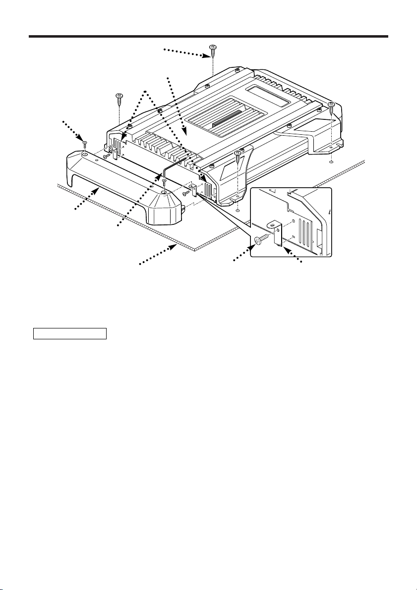
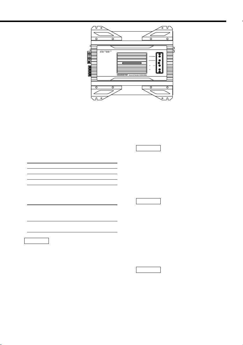
Installation
Self-tapping screw
(ø5 × 18 mm)
Hexagon socket
head cap screw
(M3 × 8 mm)
Terminal
cover
Hexagon
Wrench
Cooling fan : Air inlet
Exhaust outlet
Installation board, etc.
(thickness : 15 mm or more)
1.Install the installation fittings in the unit.
2.Attach the unit.
3.Install the terminal cover.
2CAUTION
• Do not install in the below locations;
(Unstable location, In a location that interferes with driving, In a location that gets wet, In a
dusty location, In a place that gets hot, In a place that gets direct sunlight, In a location that
gets hit by hot air)
• Do not install the unit under the carpet. Otherwise heat build-up occurs and the unit may be
damaged.
• Install this unit in a location which allows heat to easily dissipate.
Once installed, do not place any object on top of the unit.
• The surface temperature of the amplifier will become hot during use. Install the amplifier in a
place where people, resins, and other substances that are sensitive to heat will not come into
contact with it.
• This unit has cooling fans to decrease the internal temperature. Be careful not to block the
cooling fan openings when installing the unit. Blocking these openings will inhibit the cooling of
the internal temperature and result in malfunction.
• When making a hole under a seat, inside the trunk, or somewhere else in the vehicle, check
that there is nothing hazardous on the opposite side such as a gasoline tank, brake pipe, or
wiring harness, and be careful not to cause scratches or other damage.
• Do not install near the dashboard, rear tray, or air bag safety parts.
• The installation to the vehicle should securely fasten the unit to a place in which it will not
obstruct driving. If the unit comes off due to a shock and hits a person or safety part, it may
cause injury or an accident.
• After installing the unit, check to make sure that electrical equipment such as the brake lamps,
turn signal lamps and windshield wipers operate normally.
Self-tapping screws
(ø3 × 8 mm)
Mounting
Hardware
English 3
Page 4
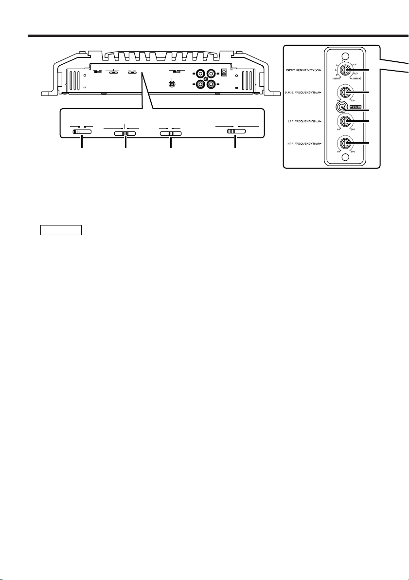
Controls / Indicator
ON
OFF
INFRASONIC
FILTER
LPF
OFF
HPF
B.M.S.
+12dB
OFF
REMOTE
OPERATION
MONO(L ch)
STEREO
GND
LINE OUT EXT.AMP.CONT.LINE IN
L
R
L
R
ON
OFF
INFRASONIC
FILTER
LPF
OFF
HPF
B.M.S.
+12dB
OFF
REMOTE
OPERATION
MONO(L ch)
STEREO
1 2 3 4
5
6
8
9
7
5 INPUT SENSITIVITY control
Adjust this control according to the pre-out
level of the center unit connected to this
amplifier.
NOTE
Refer to "Specifications" on the center
unit’s instruction manual about the pre-out
level.
4 OPERATION switch
This switch is used to select the operation
mode of the amplifier.
• STEREO position:
The amplifier can be used as a stereo
amplifier.
• MONO (Lch) position:
Amplifies the signal input from the left side
only. Set to this position and make bridged
connections to use as a high-power
monaural amplifier. (The input right signal is
not output.)
3 FILTER switch
This switch allows to apply high-pass or
low-pass filtering to the speaker outputs.
• HPF (High-Pass Filter) position:
The filter outputs the band of higher
frequencies than the frequency set with the
HPF FREQUENCY control.
•OFF position:
The entire bandwidth is output without
filtering.
• LPF (Low-Pass Filter) position:
The filter outputs the band of lower
frequencies than the frequency set with the
LPF FREQUENCY control.
The speaker output is automatically turned
monaural (L+R) and the bass boost function
is activated.
9 HPF FREQUENCY control
Sets the cutoff frequency when the FILTER
switch is set to HPF.
8 LPF FREQUENCY control
Sets the cutoff frequency when the FILTER
switch is set to LPF.
1 INFRASONIC FILTER switch
When this switch is ON, the frequencies
which are below the audible range and
therefore inaudible are cut off so that the
quality of the audible frequencies can be
improved.
2 B.M.S.(Bass management system)
switch
Bass boost centered on the frequency set
by the B.M.S. FREQUENCY control.
• +12 position:
Bass boost +12 dB
•OFF position:
Bass boost OFF
•REMOTE position:
Controls the B.M.S. from the Kenwood
center unit. (Refer to page 5)
6 B.M.S. FREQUENCY control
When the B.M.S. switch is set on "+12dB"/
"REMOTE" the emphasized center
frequency is adjusted.
7 V-COLOR (Variable color) button
Select the ON color for the indicator.
Every time the button is pressed, 7 fixed
colors and the variable color change.
The color can’t be set when the indicator is
blinking.
4 English
Page 5
■ Controlling the B.M.S. from the
Kenwood center unit
(B.M.S. : Bass management system)
When the B.M.S. switch is set in the
remote position, the bass boost amount
and frequency offset can be controlled from
the center unit.
• Bass boost
Center unit
display
"Flat"/"OFF"/"1" Bass boost OFF (Flat)
"+6"/ "1"/"2" Bass boost +6 dB
"+12"/ "2"/"3" Bass boost +12 dB
"+18"/ "3"/"4" Bass boost +18 dB
Setting
• Frequency offset
Center unit
display
"Normal" It is the B.M.S.
"Low" The central frequency is 20-
NOTE
For the center unit control method and
setting display, refer to the Instruction
Manual for the center unit.
There may be cases when the center unit
can’t set the "Bass boost +18dB" or
"Frequency Offset".
Setting
FREQUENCY control
adjustment value.
30% low.
■ Indicator 0
You are notified of the unit’s condition and
malfunction (Protection function) by the
indicator.
• ON or color change in order.
When operation is normal
NOTE
The color you want can be selected with
the variable color button.
• The color blinks blue
– When during operation
– When the center unit/B.M.S. switch
controls the B.M.S.
• The color blinks yellow
When the power voltage is less than 11V.
NOTE
The cause may be one of the below
times.
– When the vehicle battery is weak.
– When the battery capacity is low.
– When the battery cord is worn.
– When the battery wire is too small or too
long and can’t supply enough current.
• The color blinks purple
When the unit has failed and direct current
voltage is generated to the speaker’s
output.
NOTE
Turn the power OFF and release the
protection. If the indicator doesn’t quit
blinking, contact your Kenwood dealer.
• The color blinks red
When the inside of the unit is overheating.
• The color blinks green
– When the speaker cord is shorted.
– When the speaker output is in contact
with the vehicle ground.
English 5
Page 6
Connection
30
30
LEFT
BRIDGED
SPEAKER
OUTPUT
RIGHT
POWER IN
P.CON
BATT.
GND
FU
S
E(
30A
x2
)
ON
OFF
INFRASONIC
FILTER
LPF
OFF
HPF
B.M.S.
+12dB
OFF
REMOTE
OPERATION
MONO(L ch)
STEREO
GND
LINE OUT EXT.AMP.CONT.LINE IN
L
R
L
R
! @ # $ %
^ (&*
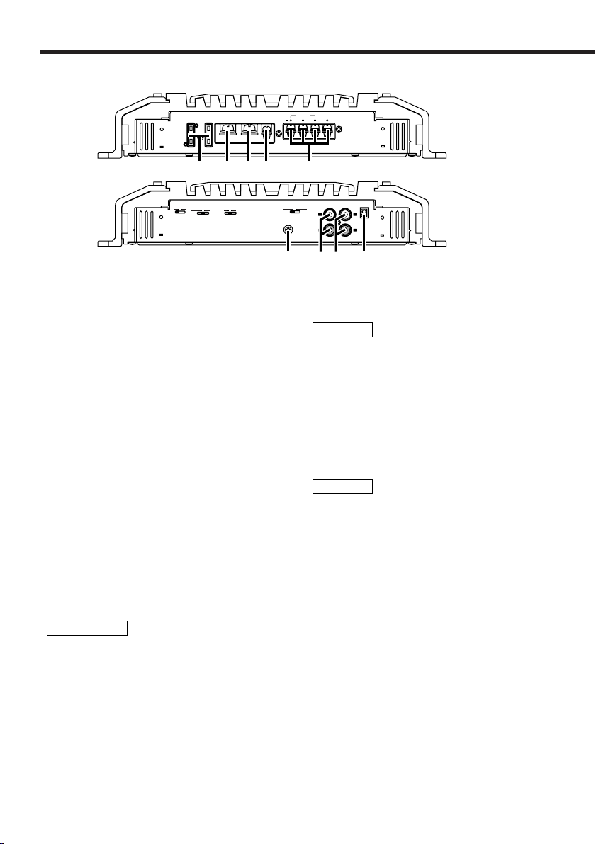
■ Terminal names
! Fuse (30 A × 2)
@ Battery terminal
# Ground terminal
% Speaker output terminals
• Stereo Connections:
When you wish to use the unit as a stereo
amplifier, stereo connections are used.
The speakers to be connected should
have an impedance of 2Ω or greater.
When multiple speakers are to be
connected, ensure that the combined
impedance is 2Ω or greater for each
channel.
• Bridged Connections:
When you wish to use the unit as a highoutput monaural amplifier, bridged
connections are used. (Make connections
to the LEFT channel 9 and the RIGHT
channel · SPEAKER OUTPUT terminals.)
The speakers to be connected should
have an impedance of 4Ω or greater.
When multiple speakers are to be
connected, ensure that the combined
impedance is 4Ω or greater.
2CAUTION
The rated input of the speakers should be no
less than the maximum output of the
amplifier. Otherwise malfunction may result.
^ RCA cable ground lead terminal
When using an RCA cable with a ground
lead attached, connect the ground lead to
this terminal.
& LINE IN terminal
* LINE OUT terminal
The signal that’s input from the line input
terminal is output.
6 English
$ Power control terminal
Controls the unit ON/OFF.
NOTE
Controls the unit power. Be sure to connect it
with all the systems.
( EXT.AMP.CONT. (external
amplifier control) terminal
Controls the B.M.S. Only Kenwood center
unit models sold in 1999 or later with a
"EXT.CONT."/"EXT.AMP.CONT." wire
attached can be used.
Also, a maximum of 3 power amplifiers can
be operated at the same time.
NOTE
There are cases when operation may not be
possible due to wiring wire type and length.
Page 7

■ Installation procedure
Since there are large variety of settings and connections possible according to applications, read
the instruction manual well to select the proper setting and connection.
1.Remove the ignition key and disconnect the negative - terminal of the battery to prevent short
circuits.
2.Set the unit according to the intended usage.
3.Connect the input and output wires of the units.
4.Connect the speaker wires.
5.Connect the power wire, power control wire and grounding wire following this order.
6.Install the unit in the car.
7.Connect the negative - terminal of the battery.
2CAUTION
• If sound is not output normally, immediately turn power off and check connections.
• Be sure to turn the power off before changing the setting of any switch.
• If the fuse blows, check wires for shorts, then replace the fuse with one of the same rating.
• Check that no unconnected wires or connectors are touching the car body. Do not remove caps
from unconnected wires or connectors to prevent short circuits.
• Connect the speaker wires to appropriate speaker connectors separately. Sharing the negative
wire of the speaker or grounding speaker wires to the metal body of the car can cause this unit
to fail.
• After installation, check that the brake lamps, winkers, and wipers work properly.
English 7
Page 8
Connection
30
30
LEFT
BRIDGED
SPEAKER
OUTPUT
RIGHT
POWER IN
P.CON
BATT.
GND
FU
S
E
(
30A
x2
)
ON
OFF
INFRASONIC
FILTER
LPF
OFF
HPF
B.M.S.
+12dB
OFF
REMOTE
OPERATION
MONO(L ch)
STEREO
GND
LINE OUT EXT.AMP.CONT.LINE IN
L
R
L
R
11 mm
P.CONT.
@#$
(
EXT.CONT.
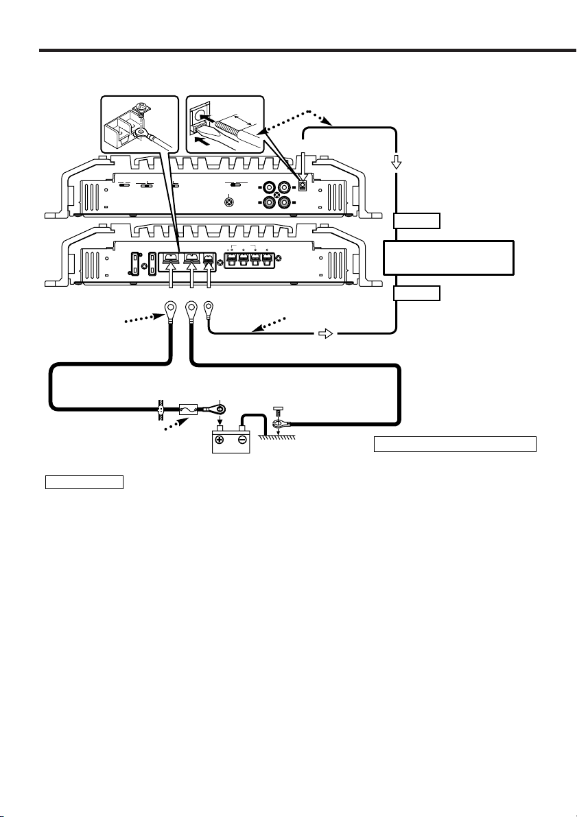
■ Power wire connection
The connecting wire diameter*
• If solid wire: Ø0.4 (AWG 26) – Ø1.2 (AWG 16)
• If multi strand wire: Ø0.4 (AWG 26) – Ø1.2 (AWG 16)
External amplifier control
wire (Pink / Black)
(Refer to page 6)
CENTER UNIT
(CD receiver, etc.)
Lead terminal*
Battery wire*
Protective Fuse*
Ground wire*
Battery
Extension wire*
Power control wire
(Blue/ White)
* : Commercially available parts
2WARNING
To prevent fire caused by a short in the wiring, connect a fusible link or breaker nearby the battery’s
positive terminal.
Wiring
•Take the battery wire for this unit directly from the battery. If it's connected to the vehicle’s
wiring harness, it can cause blown fuses etc.
• If a buzzing noise is heard from the speakers when the engine is running, connect a line noise
filter (optional) to each of the battery wire.
• Do not allow the wire to directly contact the edge of the iron plate by using Grommets.
• Connect the ground wire to a metal part of the car chassis that acts as an electrical ground
passing electricity to the battery‘s negative - terminal. Do not turn the power on if the ground
wire is not connected.
•Be sure to install a protective fuse in the power cord near the battery. The protective fuse
should be the same capacity as the unit’s fuse capacity or somewhat larger.
• For the power cord and ground, use a vehicle type (fireproof) power wring cord with a current
capacity greater than the unit’s fuse capacity. (Use a power wiring cord with a diameter of 8
2
mm
(AWG 8) or greater.)
•When more than one power amplifier are going to be used, use a power supply wiring wire and
protective fuse of greater current-handling capacity than the total maximum current drawn by
each amplifier.
EXT.AMP.CONT. (external amplifier control) terminal (
1. Peel the cladding of wire for a length of 11mm from the end.
2. While pressing the lock release button with a slotted screwdriver, insert the wire.
8 English
Page 9
30
30
Page 10
System examples
L
R
L
R
L
R
LRL
R
LRL
R
LRL
R
LRL
R
LINE OUT
¡
¡
™
™
¡
™
¡
™
12 34
ON
OFF
INFRASONIC
FILTER
LPF
OFF
HPF
B.M.S.
+12dB
OFF
REMOTE
OPERATION
MONO(L ch)
STEREO
12 34
ON
OFF
INFRASONIC
FILTER
LPF
OFF
HPF
B.M.S.
+12dB
OFF
REMOTE
OPERATION
MONO(L ch)
STEREO
12 34
ON
OFF
INFRASONIC
FILTER
LPF
OFF
HPF
B.M.S.
+12dB
OFF
REMOTE
OPERATION
MONO(L ch)
STEREO
12 34
ON
OFF
INFRASONIC
FILTER
LPF
OFF
HPF
B.M.S.
+12dB
OFF
REMOTE
OPERATION
MONO(L ch)
STEREO
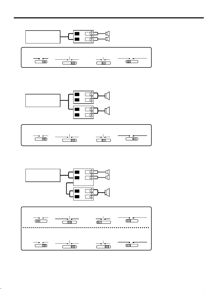
■ 2-channel system
CENTER UNIT
Left speaker
Right speaker
■ High-power 1-channel system
CENTER UNIT
■ 2-channel + Subwoofer system
CENTER UNIT
Left speaker (Bridged)
Right speaker (Bridged)
Left speaker (High pass)
Right speaker (High pass)
Subwoofer
(L + R)
(Bridged)
10 English
Page 11
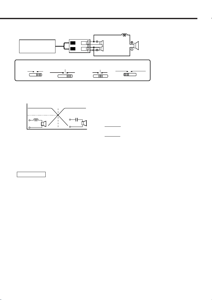
■ Tri-mode
CENTER UNIT
LRL
L
C
R
(High pass)
C
Subwoofer
(L + R) (Bridged)
INFRASONIC
12 34
OFF
ON
REMOTE
B.M.S.
OFF
+12dB
FILTER
OFF
HPF
LPF
OPERATION
STEREO
MONO(L ch)
●Principle of Tri-mode
Method of frequency band division using a coil and capacitor…in case of 6dB/oct. slope
Coil (L): Passes low frequencies and blocks high
frequencies. (Low pass)
Capacitor (C): Passes high frequencies and blocks low
frequencies. (High pass)
159000
C= (µF)
fc x R
159 x R
L= (mH)
fc
fc=Cut of Frequency (Hz)
R=Speaker Impedance (Ω)
0 dB
-3 dB
Crossover Frequency
L
C
Frequency
●Example:
When it is required to set a crossover frequency of 120 Hz using speakers with an
impedance of 4 ohms.
Prepare commercially-available coil and capacitor with the closest ratings to the results
calculated from the formula above. The capacitor rating should be as close as possible to 331.25
(µF) and the coil rating should be as close as possible to 5.3 (mH).
2CAUTION
• If you wish to bridge-connect a speaker, the speaker impedance must be no less than 4 ohms.
Connecting a speaker with an impedance lower than 4 ohms may damage the unit.
• Be sure to connect capacitors to speakers to which high frequencies will be passed. Failure to
do so will result in a drop of the combined impedance with the subwoofer.
• Ensure that the withstand voltage and current ratings of the capacitors (C) and coils (L) are
sufficient.
English 11
Page 12

Troubleshooting Guide
What might appear to be a malfunction in your unit may just be the result of slight
misoperation or miswiring. Before calling service, first check the following table for possible
problems.
PROBLEM POSSIBLE CAUSE SOLUTION
No sound.
(No sound from one side.)
(Blown fuse.)
• Input (or output) cables are
disconnected.
• Protection circuit may be
activated.
• Volume is too high.
• The speaker cord is shorted.
• Connect the input (or output)
cables.
• Check connections by referring
to "Indicator".
• Replace the fuse and use lower
volume.
• After check the speaker cord and
fixing the cause of the short,
replace the fuse.
The output level is too
small (or too large).
The sound quality is bad.
(The sound is distorted.)
The external amplifier
controller (B.M.S.) will not
work.
The input sensitivity adjusting
control is not set to the correct
position.
• The speakers wire are
connected with wrong + / polarity.
•A speaker wire is pinched by a
screw in the car body.
• The switches may be set
improperly.
• The B.M.S. switch setting is
incorrect.
• The external amplifier control
wire has come loose.
Adjust the control correctly
referring to “Controls”.
• Connect them properly checking
the + / - of the terminals and
wires well.
• Connect the speaker wire again
so that it is not pinched by
anything.
• Set switches properly by
referring to "System examples".
• The B.M.S. switch is set to
"REMOTE".
• Check that the external amplifier
control wire is properly
connected.
12 English
Page 13

Specifications
Specifications subject to change without notice.
Audio Section
Max Power Output (4 Ω)
Normal..............................................................................................................................500 W × 2
Bridged ..........................................................................................................................1000 W × 1
Rated Power Output (+B = 12.0 V)
Normal (4 Ω) (20 Hz – 20 kHz, 0.05 % THD) ......................................................................90 W × 2
Normal (2 Ω) (1 kHz, 0.5 % THD) ....................................................................................170 W × 2
Bridged (4 Ω) (1 kHz, 0.5 % THD) ....................................................................................340 W × 1
Rated Power Output (+B = 14.4 V)
Normal (4 Ω) (20 Hz – 20 kHz, 0.05 % THD) ....................................................................125 W × 2
Normal (4 Ω) (DIN : 45324 , +B = 14.4V) ........................................................................125 W × 2
Normal (2 Ω) (1 kHz, 0.5 % THD) ....................................................................................250 W × 2
Bridged (4 Ω) (1 kHz, 0.5 % THD) ....................................................................................500 W × 1
Frequency Response (+0, –3 dB)................................................................................5 Hz – 100 kHz
Total Harmonic Distortion (Rated power)#................................................................0.006 % (1 kHz)
Sensitivity (rated output) (MAX.) ................................................................................................0.2 V
Sensitivity (rated output) (MIN.) ................................................................................................5.0 V
Signal to Noise Ratio................................................................................................................105 dB
Input Impedance........................................................................................................................10 kΩ
Low Pass Filter Frequency (18 dB/oct.) ............................................................50 – 200 Hz (variable)
High Pass Filter Frequency (12 dB/oct.)............................................................50 – 200 Hz (variable)
Infrasonic Filter Frequency (24 dB/oct.) ....................................................................................15 Hz
B.M.S. (40 – 100 Hz : variable)......................................................................OFF / +6 / +12 / +18 dB
General
Operating Voltage ..................................................................................12.0 V (11 – 16 V allowable)
Current Consumption (+B = 12.0 V, 4 Ω, 10 % THD)..................................................................37 A
Dimensions (W × H × D) ......................................................................................283 × 58 × 350 mm
............................................................................................................11-1/3 × 2-5/16 × 13-3/4 inch
Weight ......................................................................................................................5.2 kg (11.5 lbs)
# Sensitivity = MIN. , Through LPF (30 kHz)
English 13
Page 14

Précautions de sécurité
2AVERTISSEMENT
Pour éviter toute blessure et/ou incendie,
veuillez prendre les précautions suivantes:
• Si vous prolongez un câble de batterie ou de
masse, assurez vous d'utiliser un câble pour
automobile ou un câble avec une section de 8
mm2(AWG8) afin d'éviter tous risques de
détérioration ou d'endommagement du
revêtement des câbles.
• Pour éviter les court-circuits, ne jamais
mettre ou laisser d'objets métalliques
(comme une pièce de monnaie ou un outil en
métal) à l'intérieur de l'appareil.
• Si l'appareil commence à émettre de la
fumée ou une odeur bizarre, mettez
immédiatement l'appareil hors tension et
consultez un revendeur Kenwood.
• Ne pas toucher l’appareil quand il est en
service car la température de sa surface est
suffisamment élevée pour provoquer des
brûlures.
2ATTENTION
Pour éviter tout dommage à l'appareil,
veuillez prendre les précautions suivantes:
• Bien vérifier que l’appareil est raccordé à une
source d’alimentation CC de 12 V avec
raccordement de masse négative.
• N'ouvrez pas le couvercle supérieur ou
inférieur de l'appareil.
• N'installez pas l'appareil dans un endroit
exposé directement à la lumière du soleil, à
une chaleur excessive ou à l'humidité. Evitez
aussi les endroits trop poussiéreux et où
l'appareil risque d'être éclaboussé.
• Lors du remplacement d'un fusible, utilisez
seulement un fusible neuf avec la valeur
indiquée. L'utilisation d'un fusible d'une
valeur différente peut être la cause d'un
mauvais fonctionnement de votre appareil.
• Pour éviter les courts-circuits lors du
remplacement d'un fusible, déconnectez
d'abord le faisceau de câbles.
REMARQUE
• Si vous rencontrez des problèmes pendant
l'installation, consultez votre revendeur
Kenwood.
• Si l'appareil semble ne pas fonctionner
correctement, consultez votre revendeur
Kenwood.
REMARQUE
Cet appareil numérique de la classe B est
conforme à la morme NMB-003 du Canada.
Nettoyage de l’appareil
Si la surface de l’appareil sale, l’essuyer avec
un chiffon au silicone ou un chiffon doux et sec
après avoir éteint l’appareil.
2ATTENTION
N'essuyez pas le panneau avec un tissu
rugueux ou imprégné de dissolvant volatile
comme un diluant à peinture ou de l'alcool. Il
pourrait rayer la surface du panneau et/ou
écailler les lettres d'informations.
Comment éviter une élévation de la
batterie
Lorsque l’unité est utilisée avec l’ACC sur ON,
sans que le moteur ne soit allumé, cela
décharge la batterie. Il est préférable de
l’utiliser après avoir allumé le moteur.
Fonction de protection
L’unité dispose d’une fonction de protection
destinée à la protéger ainsi que les hautparleurs, contre différents
dysfonctionnements. Lorsque cette fonction
est activée, vous en êtes informé par
l’indicateur correspondant. (Cf. page 17.)
Accessoires
Nom de la pièce Quantité
Vis taraudeuses
(ø5 × 18 mm)
Cache de bornier 2
Montage du Matériel
Informatique
Vis d’assemblage à six
pans creux
(M3 × 8 mm)
Vis taraudeuses
(ø3 × 8 mm)
Clé polygonale 1
Vue
extérieure
4
4
4
4
14 Frençais
Page 15

Installation
1.Mettre en place les accessoires d’installation sur l’unité.
2.Brancher l’unité.
3.Installer la façade du terminal.
2ATTENTION
• Ne pas procéder à l’installation de l’appareil si vous vous trouvez dans l’un des lieux suivants :
(Lieu instable, Lieu où la conduite du véhicule peut être gênée, Lieu exposé à l’humidité, Lieu exposé à
la poussière, Lieu surchauffé, Lieu exposé directement à la lumière du jour, Lieu exposé à l’air chaud)
• Ne pas recouvrir l’appareil d’une nappe, tapis, etc; la chaleur qui s’accumulerait risque
d’endommager l’appareil.
• Installer cet appareil à un emplacement tel que la chaleur puisse se dissiper aisément. Après
l’installation, ne placer aucum objet sur l’appareil.
• La surface de l’amplificateur va chauffer pendant l’utilisation. Installer l’amplificateur à un
endroit où des passagers, de la résine ou d’autres substances sensibles à la chaleur n’entreront
pas en contact avec lui.
• Cet appareil est pourvu de ventilateurs de façon à évacuer une partie de la chaleur produite par
les circuits internes. Il est donc indispensable, au moment de l'installation, de veiller à ce que
les ouães d'aération ne soient pas obstruées.En effet, si la chaleur interne ne peut pas être
éliminée par la ventilation de l'appareil, une anomalie de fonctionnement peut aisément
survenir.
• Lors du forage d’un trou sous le siège, à l’intérieur du coffre ou partout ailleurs dans le
véhicule, vérifier s’il n’y a pas d’élément dangereux de l’autre côté, tel qu’un réservoir à
carburant, une conduite de frein, une gaine de câbles, et faire attention de ne pas faire de
griffes ou d’autres dégâts.
• Ne pas l’installer près du tableau de bord, de la plage arrière ou d’éléments de sécurité de
l’airbag.
• Lors de l’installation dans un véhicule, l’appareil doit être fermement fixé à un endroit ou il ne
gênera pas la conduite. Si l’appareil se détache suite à un choc et heurte quelqu’un ou un
élément de sécurité, il peut occasionner des blessures ou un accident.
• Après installation de l’appareil, s’assurer que les différents équipments électriques tels que
lampes frein et les clignotants de direction fonctionnent normalement.
Frençais 15
Page 16

Contrôles / Indicateur
ON
OFF
INFRASONIC
FILTER
LPF
OFF
HPF
B.M.S.
+12dB
OFF
REMOTE
OPERATION
MONO(L ch)
STEREO
GND
LINE OUT EXT.AMP.CONT.LINE IN
L
R
16 Frençais
Page 17

Pour enlever la façade
0
Clé polygonale
Resserrer
Desserrer
Dès lors que l’on appuie sur le bouton, 7
couleurs fixes ainsi que la couleur variable
changent.
La couleur ne peut pas être réglée lorsque
l’indicateur clignote.
■ Commande du B.M.S. à partir de
l’unité principale Kenwood
(B.M.S. : Système de Contrôle des Graves)
Lorsque l’interrupteur du B.M.S. est réglé sur
la position télécommande, l’intensité et le
décalage de fréquence de l’amplificateur de
fréquences graves peuvent être commandés
à partir de l’unité principale.
• Amplificateur de fréquences graves
Affichage
de l’unité
principale
“Flat”/
“OFF”/ “1”
“+6”/
“1”/ “2”
“+12”/
“2”/ “3”
“+18”/
“3”/ “4”
Configuration
Amplificateur de fréquences
graves ETEINT (normal)
Amplificateur de fréquences
graves +6 dB
Amplificateur de fréquences
graves +12 dB
Amplificateur de fréquences
graves +18 dB
• Décalage de fréquence
Affichage de
l’unité principale
“Normal” C’est la valeur compensée.
“Low” La fréquence centrale est
REMARQUE
En ce qui concerne la procédure à suivre
pour la commande de l’unité principale et la
configuration de l’affichage, se référer au
chapitre sur l’unité principale du Manuel
d’Utilisation.
Dans certains cas, “l’amplificateur de
fréquences graves +18dB” ou “le décalage
de fréquences” ne peut être réglé à partir de
l’unité principale.
Configuration
plus basse de 20 à 30%.
■ Indicateur0
L’indicateur vous informe de l’état et des
dysfonctionnements de l’unité (Fonction de
protection).
• Lorsque l’appareil est sur ON ou
que la couleur change, le
fonctionnement est correct.
Lorsque l’appareil fonctionne normalement
La couleur souhaitée peut être sélectionnée
grâce au bouton à couleur variable.
• La couleur bleue clignote
– Au cours du fonctionnement
– Lorsque l’interrupteur de l’unité
principale/B.M.S. commande le B.M.S.
• La couleur jaune clignote
Lorsque la tension électrique est inférieure
à 11V.
REMARQUE
La raison peut être la suivante :
– La batterie du véhicule est faible.
– La capacité de la batterie est trop basse.
– Le cordon de la batterie est usé.
– Le fil électrique de la batterie est trop
court ou trop long et le courant amené
est insuffisant.
• La couleur violette clignote
Lorsque l’unité est en panne et que
l’intensité du courant continu est transmise
à la sortie haut-parleur.
REMARQUE
Eteindre l’appareil puis ôter la protection. Si
l’indicateur ne cesse de clignoter, contacter
votre revendeur Kenwood.
• La couleur rouge clignote
Lorsque l’intérieur de l’unité est en
surchauffe.
• La couleur verte clignote
– Lorsque le cordon du haut-parleur est en
court-circuit.
– Lorsque la sortie haut-parleur est en
contact avec la terre du véhicule.
Frençais 17
Page 18

Raccordements
30
30
LEFT
BRIDGED
SPEAKER
OUTPUT
RIGHT
POWER IN
P.CON
BATT.
GND
FU
S
E(
30A
x2
)
ON
OFF
INFRASONIC
FILTER
LPF
OFF
HPF
B.M.S.
+12dB
OFF
REMOTE
OPERATION
MONO(L ch)
STEREO
GND
LINE OUT EXT.AMP.CONT.LINE IN
L
R
L
R
! @ # $ %
^ (&*
■ Noms des terminaux
! FUSIBLE (30 A × 2)
@ Borne BATT (alimentation)
# Borne GND (masse)
% Bornes SPEAKER OUTPUT
• Connexions stéréo:
Pour utiliser l’appareil comme
amplificateur stéréo, des connections
stéréo doivent être utilisées.
Les haut-parleurs à connecter doivent
avoir une impédance de 2 ohms ou
supérieure. Lorsque plusieurs hautparleurs doivent être connectés, s’assurer
que l’impédance combinée soit de 2 ohms
ou supérieure pour chaque canal.
• Connexions en pont:
Pour l’utilisation de l’appareil comme
amplificateur monophonique à haute
puissance de sortie, des connections en
pont doivent être utilisées. (Faire les
connexions aux bornes SPEAKER
OUTPUT du canal gauche (LEFT) 9 et du
canal droit (RIGHT) ·.)
Les haut-parleurs à connecter doivent
avoir une impédance de 4 ohms ou
supérieure. Lorsque plusieurs hautparleurs doivent être connectés, s’assurer
que l’impédance combinée soit de 4 ohms
ou supérieure.
2ATTENTION
La puissance admissible par les haut-parleurs
doit être au moins égale à la puissance de
sortie de l'amplificateur. Dans le cas contraire,
une anomalie de fonctionnement peut
survenir.
18 Frençais
^ Borne de masse pour câble RCA
(GND)
Si on utilise une câble RCA muni d’un fil de
masse, relier le fil de masse à cette borne.
& Borne d'entrée de ligne(LINE IN)
* Sortie de ligne(LINE OUT)
Le signal entrant du terminal d’entrée de
ligne constitue la sortie.
$ Borne P.CON (fil de commande
d’alimentation)
Commande l’unité ON/OFF.
REMARQUE
Commande l’unité d’alimentation. Assurezvous de le connecter à l’ensemble des
différents systèmes.
( Borne EXT.AMP.CONT. (Contrôle
de l’amplificateur extérieur)
Commande le B.M.S. Seuls les modèles
d’unités principales Kenwood vendus au
cours de 1999 ou après cette date et
disposant d’un câble "EXT.CONT."/
"EXT.AMP.CONT." peuvent être utilisés. En
outre, 3 amplificateurs de puissance peuvent
fonctionner simultanément.
REMARQUE
Dans certains cas, l’appareil peut ne pas
fonctionner en raison du type ou de la
longueur du câble électrique.
Page 19

■ Procédure d'installation
Etant donné que le nombre de réglages et de raccordements est assez important, il importe de
prendre pleinement connaissance du mode d'emploi.
1.Retirer la clé de contact et débrancher la borne négative - de la batterie pour éviter les courtcircuits.
2.Régler l'appareil en fonction de l'utilisation désirée.
3.Raccorder les câbles d’entrée et de sortie de l’appareil.
4.Raccorder les câbles de haut-parleur.
5.Relier, dans l'ordre, le câble d'alimentation, le câble de commande d'alimentation et le câble de
masse.
6.Monter l’appareil dans la voiture.
7.Raccorder la borne négative - de la batterie.
2ATTENTION
• En cas d'anomalie, mettre immédiatement l'appareil hors tension et vérifier tous les
raccordements.
• Veiller à mettre l'appareil hors tension avant de changer la position des commutateurs.
• Si le fusible saute, vérifier si les câbles ne sont pas court-circuités, et remplacer le fusible par
un autre fusible de même capacité nominale.
• Vérifier qu’aucun câble ou connecteur non raccordé ne touche la carrosserie de la voiture. Ne
pas retirer les capuchons des câbles ou connecteurs non raccordés afin d’éviter tout
courtcircuit.
• Raccorder séparément les câbles de haut-parleur aux connecteurs de haut-parleur appropriés.
La mise en commun du câble négatif d’un haut-parleur ou des fils de masse des haut-parleurs à
la carrosserie métallique de la voiture pourrait rendre l’appareil inopérant.
• Après l’installation, vérifier que les voyants de frein, les clignotants et les essuie-glace
fonctionnent correctement.
Frençais 19
Page 20

Raccordements
30
30
LEFT
BRIDGED
SPEAKER
OUTPUT
RIGHT
POWER IN
P.CON
BATT.
GND
FU
S
E
(
30A
x2
)
ON
OFF
INFRASONIC
FILTER
LPF
OFF
HPF
B.M.S.
+12dB
OFF
REMOTE
OPERATION
MONO(L ch)
STEREO
GND
LINE OUT EXT.AMP.CONT.LINE IN
L
R
L
R
11 mm
P.CONT.
@#$
(
EXT.CONT.
■ Connexion du câble d’alimentation
Diamètre du fil électrique*
• Fil massif : Ø0.4 (AWG 26) – Ø1.2 (AWG 16)
• Fil multi brins : Ø0.4 (AWG 26) – Ø1.2 (AWG 16)
Câble de commande de
l’amplificateur externe
(rose/noir) (Cf. page 18.)
Unité centrale
(récepteur/lecteur de CD, etc.)
Cosse pour
câble*
Câble de la batterie*
Fusible de protection*
2AVERTISSEMENT
Câble de masse*
Câble de rallonge*
Batterie
Câble de commande de
l’alimentation
(Bleu/Blanc)
* : disponible dans le commerce
Pour éviter tout incendie dû à un court-circuit, insérer un fusible ou un coupecircuit à proximité de la
borne de la batterie.
Câblage
• Pour cette unité, brancher le cordon de la batterie directement à la batterie. Si celui-ci est connecté
à l’installation électrique du véhicule, l’installation peut disjoncter etc.
• Si un ronronnement se fait entendre dans les haut-parleurs lorsque le moteur tourne, fixer un filtre
antiparasite de ligne (en option) au câble de la batterie.
• Utiliser un passe-câble de manière que le cordon ne soit pas en contact avec le tablier.
• Relier les fils de masse à une partie métallique du châssis du véhicule qui soit en mesure de jouer le
rôle de masse électrique et donc de laisser passer le courant vers le pôle négatif - de la batterie. Ne
pas mettre l’appareil sous tension si les fils de masse ne sont pas reliés.
• Assurez-vous de mettre en place un fusible protégeant le cordon d’alimentation situé près de la
batterie. Ce fusible doit avoir un pouvoir de coupure égal ou légèrement supérieur à celui de l’unité.
• En ce qui concerne le cordon d’alimentation et la terre, il est conseillé d’utiliser un cordon
d’alimentation électrique pour voiture (ininflammable) dont l’intensité sera supérieure au pouvoir de
coupure du fusible de l’unité. (Utiliser un cordon d’alimentation d’un diamètre égal ou supérieur à 8
2
mm
(AWG 8).)
• Lorsque plus d’un amplificateur de puissance doivent être utilisés, utiliser un câble de câblage
d’alimentation et un fusible de sécurité dont la limite de tension est supérieure au courant total
maximum tiré par chaque amplificateur.
Borne EXT.AMP.CONT. (Contrôle de l’amplificateur extérieur) (
1Dénuder le fil électrique sur une longueur de 11 mm à partir de la fin.
2 Tout en appuyant sur le verrou, appuyer sur la touche de détachement à l’aide d’un tournevis
pour écrous à fente puis insérer le fil électrique.
20 Frençais
Page 21

30
30
LEFT
BRIDGED
SPEAKER
OUTPUT
RIGHT
POWER IN
P.CON
BATT.
GND
FU
S
E
(
30A
x2
)
Page 22

Exemple de configuration
L
R
L
R
L
R
LRL
R
LRL
R
LRL
R
LRL
R
LINE OUT
¡
¡
™
™
¡
™
¡
™
12 34
ON
OFF
INFRASONIC
FILTER
LPF
OFF
HPF
B.M.S.
+12dB
OFF
REMOTE
OPERATION
MONO(L ch)
STEREO
12 34
ON
OFF
INFRASONIC
FILTER
LPF
OFF
HPF
B.M.S.
+12dB
OFF
REMOTE
OPERATION
MONO(L ch)
STEREO
12 34
ON
OFF
INFRASONIC
FILTER
LPF
OFF
HPF
B.M.S.
+12dB
OFF
REMOTE
OPERATION
MONO(L ch)
STEREO
12 34
ON
OFF
INFRASONIC
FILTER
LPF
OFF
HPF
B.M.S.
+12dB
OFF
REMOTE
OPERATION
MONO(L ch)
STEREO
■ Système 2 voies
Unité centrale
Haut-parleur gauche
Haut-parleur droit
■ Système 1 voie, puissance élevée
Unité centrale
■ Système 2 voies + enceinte d'extrêmes graves
Unité centrale
Haut-parleur gauche (Pont)
Haut-parleur droit (Pont)
Haut-parleur gauche
(filtre passe-haut)
Haut-parleur droit
(filtre passe-haut)
Haut-parleurs d'extrêmes
graves (L+R) (Pont)
22 Frençais
Page 23

■ Le Tri-mode
L
C
Unité centrale
LRL
L
C
R
filtre passehaut
C
Haut-parleurs d'extrêmes
graves (L+R) (Pont)
INFRASONIC
12 34
OFF
ON
REMOTE
B.M.S.
OFF
+12dB
FILTER
OFF
HPF
LPF
OPERATION
STEREO
MONO(L ch)
●Principe du Tri-mode
Méthode de division de la bande des basses fréquences au moyen d’une bobine et d’un
condensateur … dans le cas d’une pente de 6dB/oct.
0 dB
Fréquence de recoupement
-3 dB
Self (L) : Elle laisse passer les frequences graves mais bloque
les fréquences aiguës (filtre passe-bas).
Condensateur (C) : Il laisse passer les fréquences aiguës
mais bloque les fréquences graves (filtre
passe-haut).
159000
Fréquence
C= (µF)
fc x R
159 x R
L= (mH)
fc
fc=Fréquence de recoupement (Hz)
R=Impédance du haut-parleur (Ω)
●Exemple:
Cas où il faut établir la fréquence de transition à 120 Hz en utilisant des haut-parleurs
ayant une impédance de 4 ohms.
Se procurer dans le commerce la bobine et le condensateur présentant des caractéristiques
aussi proches que possible des valeurs calculées. Dans ce cas, la condensateur doit avoir une
capacité aussi proche que possible de 331,25 (µF), et le bobine une capacité aussi proche que
possible de 5,3 (mH).
2ATTENTION
• Si l’on désire connecter en pont un haut-parleur, l’impédance du haut-parleur ne devra pas être
inférieure à 4 ohms. Le branchement d’un haut-parleur dont l’impédance est inférieure à 4
Ohms peut endommager l’appareil.
• S’assurer de connecter des condensateurs aux haut-parleur qui recevront des hautes
fréquences. Sinon, une diminution de l’impédance combinée avec le subwoofer va se produire.
• Vérifier si la tension de tenue et les données limites de courant des condensateurs (C) et
bobines (L) sont suffisantes.
Frençais 23
Page 24

Guide de depannage
Ce qui peut apparaître comme un mauvais fonctionnement de votre appareil n’est peut être
que le résultat d’une mauvaise opération ou d’une mauvaise connexion. Avant d’appeler un
centre de service, vérifiez d’abord dans le tableau suivant les problèmes possibles.
PROBLEME CAUSE POSSIBLE SOLUTION
Absence de sons. (Pas de
son d’un côté)
(Fusible grillé)
• Les câbles d’entrée (ou de sortie)
sont débranchés.
• Le circuit de protection peut être
actionné.
• Le volume est trop fort.
• Les fils de raccordement
d’enceinte sont en court-circuit.
• Brancher les câbles d’entrée (ou de
sortie).
• Vérifier les raccordements en se
reportant au paragraphe
"Indicateur".
• Remplacez le fusible et utilisez un
niveau de volume plus faible.
• Après avoir vérifié le câble
d’enceinte et réparé la cause du
court-circuit, remplacez le fusible.
Niveau de sortie trop
faible. (ou trop fort)
La qualité sonore est
manuvaise. (Le son est
distordu.)
Le contrôle de
l’amplificateur externe
(B.M.S.) ne fonctionnera
pas.
La commande de réglage de la
sensibilité d’entrée n’est pas
amenée sur la bonne position.
• Les câbles de haut-parleur ont été
raccordés en inversant la polarité
+/-.
• Un câble de haut-parleur est pincé
par une vis dans le châssis de la
voiture.
• Les commutateurs ne sont peutêtre pas positionnés comme il
convient.
• La configuration de l’interrupteur
du B.M.S. est incorrecte.
• Le cordon du contrôle de
l’amplificateur extérieur s’est
relâché.
Faire le réglage correctement en se
reportant aux indications données en
“Contrôles”.
• Raccorder correctement en
respectant les indications + et des bornes et des câbles.
• Rebrancher le câble de haut-parleur
en évitant tout pincement
• Positionner les commutateurs en
tenant compte des indications
fournies aux paragraphes
"Exemples de système".
• Le commutateur B.M.S. est mis
sur "REMOTE".
• Vérifiez que le cordon du contrôle
de l’amplificateur extérieur est
connecté correctement.
24 Frençais
Page 25

Spécifications
Les spécifications sont sujettes à modifications sans préavis.
Section audio
Puissance de sortie max. (4 Ω)
Normal..............................................................................................................................500 W × 2
En pont ..........................................................................................................................1000 W × 1
Puissance de sortie norminale (+B = 12,0 V)
Normal (4 Ω) (20 Hz – 20, 0,05 % D.H.T.) ..........................................................................90 W × 2
Normal (2 Ω) (1 kHz, 0,5 % D.H.T.) ..................................................................................170 W × 2
En pont (4 Ω) (1 kHz, 0,5 % D.H.T.) ................................................................................340 W × 1
Puissance de sortie norminale (+B = 14,4 V)
Normal (4 Ω) (20 Hz – 20, 0,05 % D.H.T.) ........................................................................125 W × 2
Normal (4 Ω) (DIN : 45324 , +B = 14,4V) ........................................................................125 W × 2
Normal (2 Ω) (1 kHz, 0,5 % D.H.T.) ..................................................................................250 W × 2
En pont (4 Ω) (1 kHz, 0,5 % D.H.T.) ................................................................................500 W × 1
Réponse en fréquence (+0, –3 dB) ............................................................................5 Hz – 100 kHz
Distorsion harmonique totale (puissance nominale)#..................................................0,006 % (1 kHz)
Sensibilité (puissance nominale) (Max.) ......................................................................................0,2 V
Sensibilité (puissance nominale) (Min.) ......................................................................................5,0 V
Rapport signal/bruit..................................................................................................................105 dB
Impédance d’entrée ..................................................................................................................10 kΩ
Fréquence du filtre passe-bas (18 dB/oct.)........................................................50 – 200 Hz (variable)
Fréquence du filtre passe-haut (12 dB/oct.) ......................................................50 – 200 Hz (variable)
Fréquence de coupure du filtre infrasonore (24 dB/oct.)............................................................15 Hz
B.M.S. (40 – 100 Hz : variable) ................................................................ETEINT / +6 / +12 / +18 dB
Générales
Tension de fonctionnement ....................................................................14,4 V (11 – 16 V possibles)
Consommation (+B = 12,0 V, 4 Ω, 10 % D.H.T.) ........................................................................37 A
Dimensions (l × h × p) ..........................................................................................283 × 58 × 350 mm
............................................................................................................11-1/3 × 2-5/16 × 13-3/4 inch
Poids ..........................................................................................................................5,2 kg (11,5 lbs)
# Sensibilité minimale, à travers le filtre passe-bas (30 kHz)
Frençais 25
Page 26

Precauciones de seguridad
2ADVERTENCIA
Para evitar el riesgo de lesiones y/o fuego,
observe las siguientes precauciones:
• Cuando extienda los cables de la batería o de
masa, asegúrese de utilizar cables para
automóviles u otros cables que tengan un
área de 8 mm2(AWG8) o más, para evitar el
deterioro del cable y daños en su
revestimiento.
• Para evitar cortocircuitos, nunca coloque ni
deje objetos metálicos (por ejemplo,
monedas o herramientas metálicas) dentro de
la unidad.
• Si nota que la unidad emite humos u olores
extraños, desconecte inmediatamente la
alimentación y consulte con su distribuidor
Kenwood.
• No toque el aparato mientras lo utiliza porque
su superficie se calienta y puede causar
quemaduras si se toca.
2PRECAUCIÓN
Para evitar daños en la unidad, tome las
siguientes precauciones:
• Asegúrese de que la unidad está conectada a
un suministro de alimentación de CC de 12V
con una conexión de toma de tierra negativa.
• No abra las cubiertas superior o inferior de la
unidad.
• No instale la unidad en un sitio expuesto a la
luz directa del sol, o excesivamente húmedo
o caluroso. Asimismo evite los lugares muy
polvorientos o sujetos a salpicaduras de agua.
• Cuando tenga que reemplazar un fusible,
utilice únicamente uno del régimen prescrito.
El uso de un fusible de régimen incorrecto
podría ocasionar un funcionamiento
defectuoso de la unidad.
• Para evitar cortocircuitos mientras sustituye
el fusible, desconecte previamente el mazo
de conductores.
NOTA
• Si tiene problemas durante la instalación,
consulte con su distribuidor Kenwood.
• Si la unidad no está funcionando
correctamente, consulte con su distribuidor
Kenwood.
Limpieza de la unidad
Si la superficie de la unidad está sucia, apague
la unidad y limpie con un paño siliconado suave
y seco.
2PRECAUCIÓN
No limpie el panel con un paño áspero o
humedecido con disolventes volátiles tales
como diluyente de pintura o alcohol. Su uso
podría rayar la superficie del panel y/o hacer
que se despeguen las letras indicadoras.
Para evitar agotar la batería
Cuando la unidad se utiliza en la posición ACC
ON sin CONECTAR el motor, agota la batería.
Utilícelo después de arrancar el motor.
Función de protección
Existe una función de Protección instalada en
la unidad para proteger ésta y los altavoces de
diversos problemas que pudieran presentarse.
Cuando está activada la función de Protección,
el indicador le informa de esta condición.
(Consulte la página 29)
Accesorios
Nombre de pieza Unidades
Tornillo autorroscantes
(ø5 × 18 mm)
Cubierta de
terminales
Tornillería de
montaje
Tornillo de cabeza
hexagonal (M3 × 8 mm)
Tornillo autorroscantes
(ø3 × 8 mm)
Llave hexagonal 1
Vista
exterior
4
2
4
4
4
26 Español
Page 27

Instalación
Tornillo autorroscantes
(ø5 × 18 mm)
Tablero de instalación, etc.
(grosor: 15 mm o más)
1.Coloque los elementos de instalación en la unidad.
2.Coloque la unidad.
3.Instale la cubierta del terminal.
2PRECAUCIÓN
• No instale el equipo en las siguientes ubicaciones;
(Ubicación inestable; En un lugar que interfiera a la conducción; En un lugar en el que pueda
mojarse; En un lugar con exceso de polvo; En un lugar en el que pueda recalentarse; En un
lugar en el que reciba la luz directa del sol; En un lugar situado en el flujo de aire caliente)
• No utilice el aparato bajo una alfombra porque en caso contrario, éste podría sobrecalentarse y
estropearse.
• Instale este aparato en un lugar donde el calor pueda disiparse fácilmente.
Una vez instalado, no ponga nada sobre él.
• La temperatura de la superficie del amplificador se elevará durante su uso. Instale el
amplificador en un lugar seguro donde personas, resinas y otras substancias sensibles al calor
no entren en contacto con esta superficie.
• Esta unidad tiene ventiladores de enfriamiento para reducir la temperatura interior. Tenga
cuidado para no tapar las aberturas de los ventiladores de enfriamiento cuando instale la
unidad. Al tapar estas aberturas no podrá reducirse adecuadamente la temperatura interior y
podrá producirse un fallo en el funcionamiento.
• Cuando haga un orificio bajo el asiento o en el portaequipajes o en algún otro lugar del vehículo,
verifique que no existan objetos peligrosos al lado opuesto tales como un tanque de gasolina,
tubo del freno, o los alambres del cableado del coche y tenga cuidado de no rayar las piezas del
vehículo o causar algún otro daño.
• No lo instale cerca del panel de controles, bandeja trasera, o piezas de seguridad del colchón
de aire.
• La instalación de esta unidad debe ser realizada en un lugar donde no estorbe la conducción. Si
la unidad se sale de su posición debido a un choque y golpea a una persona o a alguna pieza de
seguridad, puede causar o un accidente.
• Después de instalar el aparato, cerciórese de que los equipos eléctricos (luces de freno,
intermitentes y limpiadores) funcionen normalmente.
Español 27
Page 28

Controles / Indicador
28 Español
Page 29

Desmontar la cubierta
Llave hexagonal
Apretar
Aflojar
El col0or no puede ajustarse cuando el
indicador parpadea.
■ Control del B.M.S. desde la
unidad central Kenwood
(B.M.S. : Sistema de gestión de bajos)
Cuando el interruptor B.M.S. se ajusta en la
posición REMOTE, la cantidad de refuerzo
de bajos y el desplazamiento de frecuencia
pueden controlarse desde la unidad central.
• Refuerzo de bajos
Pantalla de
unidad central
"Flat"/"OFF"/"1" Refuerzo de bajos OFF
"+6"/ "1"/"2" Refuerzo de bajos +6 dB
"+12"/ "2"/"3" Refuerzo de bajos +12
"+18"/ "3"/"4" Refuerzo de bajos +18
Ajuste
(Plano)
dB
dB
• Desplazamiento de frecuencia
Pantalla de
unidad central
"Normal" Es el valor ajustado.
"Low" La frecuencia central es un
NOTA
Para conocer el ,método de control de la
unidad central y la pantalla de ajustes,
consulte el Manual de instrucciones de la
unidad central.
Pueden darse casos en los que la unidad
central no puede ajustar “Refuerzo de bajos
+18dB” o “Desplazamiento de frecuencia”.
Ajuste
20-30% menor.
■ Indicador0
Se le indica la condición y
malfuncionamiento de la unidad (función
Protección) mediante este indicador.
•ON o cambio de color es en orden.
Cuando el funcionamiento es normal
NOTA
Puede seleccionar el color que desee con el
botón de color variable.
• Parpadea en azul
– Durante el funcionamiento
– Cuando la unidad central/interruptor
B.M.S. controla el B.M.S.
• Parpadea en amarillo
Cuando la tensión de corriente es menor de
11V.
NOTA
La causa puede ser una de las
siguientes.
– Cuando la batería del vehículo está débil.
– Cuando la capacidad e la batería es baja.
– Cuando el cable de la batería está
desgastado.
– Cuando el cable de la batería es
demasiado pequeño o largo y no puede
suministrar corriente suficiente.
• Parpadea en púrpura
Cuando la unidad ha fallado y se genera
tensión de corriente directa hacia la salida
del altavoz.
NOTA
DESCONECTE la alimentación y liere la
protección. Si el indicador no deja de
parpadear, póngase en contacto con el
distribuidor Kenwood.
• Parpadea en rojo
Cuando el interior de la unidad se
recalienta.
• Parpadea en verde
– Cuando el cable del altavoz está en corto.
– Cuando la salida del altavoz hace contacto
con la masa del vehículo.
Español 29
Page 30

Conexiones
30
30
LEFT
BRIDGED
SPEAKER
OUTPUT
RIGHT
POWER IN
P.CON
BATT.
GND
FU
S
E(
30A
x2
)
ON
OFF
INFRASONIC
FILTER
LPF
OFF
HPF
B.M.S.
+12dB
OFF
REMOTE
OPERATION
MONO(L ch)
STEREO
GND
LINE OUT EXT.AMP.CONT.LINE IN
L
R
L
R
! @ # $ %
^ (&*
■ Nombres de los terminales
! FUSIBLE (30 A × 2)
@ Terminal BATT (alimentación)
# Terminal GND (tierra)
% Terminales SPEAKER OUTPUT
• Conexiones estereofónicas:
Cuando desee usar la unidad como un
amplificador estereofónico, usted deberá
utilizar conexiones estereofónicas.Los
altavoces a conectar deberán tener una
impedancia de 2 ohmios o mayor. Cuando
vaya a conectar múltiples altavoces,
asegúrese de que la impedancia combinada
sea de 2 ohmios o mayor para cada canal.
• Conexiones en puente:
Cuando desee usar la unidad como un
amplificador monoauricular de alta potencia,
usted deberá utilizar conexiones en puente.
(Haga las conexiones a los terminales de
salida de altavoces (SPEAKER OUTPUT) de
los canales izquierdo (LEFT) 9 y derecho
(RIGHT) ·.)
Los altavoces a conectar deberán tener una
impedancia de 4 ohmios o mayor. Cuando
vaya a conectar múltiples altavoces,
asegúrese de que la impedancia combinada
sea de 4 ohmios o mayor.
2PRECAUCIÓN
La entrada nominal de los altavoces no
deberá ser inferior a la salida máxima del
amplificador. De lo contrario podría
producirse una falla en el funcionamiento.
^ Terminal GND (alambre de tierra
del cable RCA)
Cuando utilice un cable RCA con cable de
masa incorporado, conecte el cable de
masa a esta terminal.
30 Español
& Terminal LINE IN (entrada de
linea)
* Tomas de salida de linea (LINE
OUT)
La señal de entrada del terminal de entrada
de línea es la salida.
$ Terminal del control de corriente
(P.CON)
Controla la CONEXIÓN / DESCONEXIÓN de
la unidad.
NOTA
Controla la potencia de la unidad. Asegúrese
de conectarlo con todos los sistemas.
( Terminal de control de amperaje
de salida (EXT.AMP.CONT. )
Controla el B.M.S. Sólo los modelos de
unidad central Kenwood vendidos en 1999
o con posterioridad con un cable
“EXT.CONT.”/”EXT.AMP.CONT.”
conectado podrán utilizarse. Además, un
máximo de 3 amplificadores de potencia
pueden funcionar al mismo tiempo.
NOTA
Se dan casos en los que no es posible el
funcionamiento debido al tipo y longitud del
cable empleado en el cableado.
Page 31

■ Procedimiento de instalación
Como se puede hacer una gran variedad de ajustes y conexiones según las aplicaciones, lea
atentamente el manual de instrucciones para seleccionar el ajuste y la conexión apropiados.
1.Retire la llave de encendido y desconecte el terminal negativo - de la batería para evitar
cortocircuitos.
2.Prepare el aparato según el uso que vaya a hacer de él.
3.Conecte los cables de entrada y salida de las unidades.
4.Conecte los cables del altavoz.
5.Conecte el cable de alimentación, el cable de control de alimentación y el cable de tierra en
este orden.
6.Instale la unidad en el automóvil.
7.Conecte la terminal negativa - de la batería.
2PRECAUCIÓN
• Si el sonido no sale normalmente, desconecte inmediatamente la alimentación y compruebe las
conexiones.
• No se olvide de desconectar la alimentación antes de cambiar el ajuste de cualquier
conmutador.
• Si el fusible se quema, compruebe que no haya un cortocircuito en los cables, luego cambie el
fusible por uno que tenga el mismo amperaje.
• Verifique que ninguno de los cables o conectores que están sin conectar se encuentren
tocando la carrocería del automóvil. No retire las tapas de los cables o conectores que están sin
conectar para evitar de que se produzcan cortocircuitos.
• Conecte los cables del altavoz a los conectores adecuados del altavoz separadamente. La
puesta en contacto de terminales de altavoces distintos, o la conexión como toma de tierra de
los terminales del altavoz al coche del automóvil, pueden causar daños a la unidad.
• Después de la instalación, compruebe que las lámparas del freno, luces de destello y
limpiaparabrisas funcionar correctamente.
Español 31
Page 32

Conexiones
2ADVERTENCIA
Para evitar incendios producidos por cortocircuitos en el cableado, conecte un fusible o
cortacircuito entre la batería y los terminales de la batería.
Cableado
• Lleve el cable de la batería de esta unidad directamente desde la propia batería. Si se conectara
al arnés del cableado del vehículo, puede provocar daños en los fusibles, etc.
• Si se produce un ruido de zumbido por los altavoces mientras funciona el motor, conecte un
filtro de ruido de línea (vendido por separado) a cada cable de la batería.
• No permita que el cable entre en contacto directo con el borde de la placa de hierro, utilizando
para ello arandelas de caucho.
• Conecte los cables de masa a una parte del chasis del automóvil que actúe como puesta a
masa por donde pase la electricidad hasta el borne negativo - de la batería. No conecte la
alimentación si no están conectados los cables de masa.
• Asegúrese de instalar un fusible de protección en el cable de corriente cerca de la batería. El
fusible positivo debería tener la misma capacidad que el de la unidad o algo mayor.
• Para el cable de corriente y la masa, utilice un cable de corriente para vehículos (ignífugo) con
una capacidad mayor que la capacidad del fusible de la unidad. (Utilice un cable de corriente
con un diámetro de 8 mm
• Cuando desee utilizar más de un amplificador de potencia, utilice un cable de suministro de
alimentación y un fusible de protección de una capacidad de soporte de corriente mayor a la
corriente máxima total utilizada por cada amplificador.
Terminal de control de amperaje de salida (EXT.AMP.CONT. ) (
1. Pele el revestimiento del cable unos 11 mm desde el extremo.
2. Mientras presiona el botón de liberación con un destornillador de pala, introduzca el cable.
2
(AWG 8) o mayor)
32 Español
Page 33

30
30
LEFT
BRIDGED
SPEAKER
OUTPUT
RIGHT
POWER IN
P.CON
BATT.
GND
FU
S
E
(
30A
x2
)
30
30
LEFT
BRIDGED
SPEAKER
OUTPUT
RIGHT
POWER IN
P.CON
BATT.
GND
F
U
SE
(
30
A
x2
)
ON
OFF
INFRASONIC
FILTER
LPF
OFF
HPF
B.M.S.
+12dB
OFF
REMOTE
OPERATION
MONO(L ch)
STEREO
GND
LINE OUT EXT.AMP.CONT.LINE IN
L
R
L
R
%
%
&
^
■ Conexión de cable de RCA y cable de los altavoces
* : pieza de venta en el
Terminal del cable de masa
del cable RCA
Entrada izquierda
Entrada derecha
Altavoz
Terminal de cable*
(Conexiones estereofónicas)
derecho
Altavoz
izquierdo
comercio especializado
Cable RCA*
APARATO CENTRAL
(reproductor de discos
compactos, etc.)
(Conexiones en puente)
Altavoz (Puenteada)
■ Selección de altavoces
• La potencia de entrada asignada de los altavoces que se conecten al amplificador debe ser
mayor que la potencia de salida máxima (en Wats) del amplificador. Utilizar altavoces que
posean potencias de entrada menores a la salida de entrada del amplificador producirá
emisiones de humo y daños.
• La impedancia de los altavoces que se conecten al amplificador debe ser de 2Ω o más (para las
conexiones estéreo), o de 4Ω o más (para las conexiones en puente). Cuando desea utilizar más
de un juego de altavoces, calcule la impedancia combinada de estos altavoces y luego conecte
adecuadamente los altavoces al amplificador.
4 Ω
2Ω
2Ω
Impedancia combinada
4 Ω
8Ω 8Ω
4Ω
4Ω4Ω4Ω
4 Ω
Español 33
Page 34

Ejemplos del sistema
L
R
L
R
L
R
LRL
R
LRL
R
LRL
R
LRL
34 Español
Page 35

■ Tri-modo
L
C
Aparato Central
LRL
L
C
R
(Paso alto)
C
Altavoz de subgraves
(L + R) (Puenteada)
INFRASONIC
12 34
OFF
ON
REMOTE
B.M.S.
OFF
+12dB
FILTER
OFF
HPF
LPF
OPERATION
STEREO
MONO(L ch)
●Propiedades de las bobinas y de los capacitores
Método de división de bandas de frecuencias utilizando una bobina y un capacitor … en el
caso de una inclinación de 6 dB/octava
Bobina (L): Deja paso a las bajas frecuencias y bloquea
las altas frecuencias. (Paso bajo)
Capacitor (C): Deja paso a las altas frecuencias y
bloquea las bajas frecuencias. (Paso alto)
159000
C= (µF)
fc x R
159 x R
L= (mH)
fc
fc=Frecuencia de cruce (Hz)
R=Impedancia de altavoces (Ω)
0 dB
-3 dB
●
Ejemplo:
Frecuencia de cruce
Frecuencia
Cuando sea necesario ajustar una frecuencia de cruce de 120 Hz utilizando altavoces con
una impedancia de 4 ohmios.
Prepare una bobina y un capacitor de venta en el comercio del ramo que tengan unas
especificaciones nominales lo más parecidas a los resultados calculados en la fórmula de
arriba. Las especificaciones nominales del capacitor deberán ser lo más parecido posible a
331,25 (µF), y las especificaciones nominales de la bobina deverán ser lo más parecido
posible a 5,3 (mH).
2PRECAUCIÓN
• Si se desea conectar en puente un altavoz, la impedancia del altavoz no debe ser inferior a 4
ohmios.Conectar un altavoz con una impedancia inferior a 4 ohmios pueden estropear el
aparato.
• Asegúrese de conectar los capacitores a los altavoces por los que pasarán las altas frecuencias.
No conectar los capacitores o hacerlo de manera deficiente resultará en una caída de la
impedancia de combinación con el subwoofer.
• Asegúrese de que la tensión soportada y la capacidad nominal de corriente de los capacitores
(C) y bobinas (L) sean suficientes.
Español 35
Page 36

Guia Sobre Localización De Averias
Lo que podría parecer una falla de funcionamiento de su unidad podría ser simplemente el
resultado de un pequeño error de operación o de un defecto de conexión. Antes de acudir al
servicio, verifique primero el siguiente cuadro sobre los problemas que se podrían presentar.
PROBLEMA CAUSA POSIBLE SOLUCION
No hay sonido.
(No hay sonido de un lado.)
(Fusible fundido)
El nivel de salida está muy
bajo (o muy alto)
La calidad del sonido es
mala.
(El sonido está
distorsionado.)
El controlador del
amplificador externo
(B.M.S.) no funcionará.
• Los cables de entrada (salida)
están desconectados.
• El circuito de protección puede
estar activado.
• El volumen está demasiado alto.
• El cable del altavoz está
cortocircuitado.
El control de ajuste de
sensibilidad de entrada no está
en la posición correcta.
• Los cables de los altavoces
están conectados con las
polaridades + / - invertidas.
• Un cable de altavoz está
pellizcado por un tornillo de la
carrocería del automóvil.
• Los conmutadores pueden estar
mal ajustados.
• El ajuste del interruptor B.M.S.
es incorrecto.
• Se ha aflojado el cable del
controlador del amplificador
externo.
• Conecte los cables de entrada (o
salida).
• Compruebe las conexiones
consultando "Indicador".
• Reemplace el fusible y utilice
volumen bajo.
• Después de revisar el cable del
altavoz y arreglar la causa del
cortocircuito, reemplace el
fusible.
Ajuste bien el control consultando
en “Controles”.
• Conéctelos correctamente
asegurándose bien de cuáles son
los terminales + y -.
• Vuelva a conectar los cables de
los altavoces de forma que no
queden pellizcados.
• Ponga bien los conmutadores
consultando "Ejemplos del
sistema".
• El interruptor B.M.S. se ajusta a
"REMOTE".
• Compruebe que el cable del
controlador del amplificador
externo se encuentre
correctamente conectado.
36 Español
Page 37

Especificaciones
Especificaciones sujetas a cambios sin previo aviso.
Sección de audio
Máxima potencia de salida (4 Ω)
Normal..............................................................................................................................500 W × 2
Puenteada ......................................................................................................................1000 W × 1
Salida de potencia nominal (+B = 12,0 V)
Normal (4 Ω) (20Hz – 20kHz, 0,05 % de distorsión armónica total) ..................................90 W × 2
Normal (2 Ω) (1kHz, 0,5 % de distorsión armónica total) ................................................170 W × 2
Puenteada (4 Ω) (1kHz, 0,5 % de distorsión armónica total)............................................340 W × 1
Salida de potencia nominal (+B = 14,4 V)
Normal (4 Ω) (20Hz – 20kHz, 0,05 % de distorsión armónica total) ................................125 W × 2
Normal (4 Ω) (DIN : 45324 , +B = 14.4V) ........................................................................125 W × 2
Normal (2 Ω) (1kHz, 0,5 % de distorsión armónica total) ................................................250 W × 2
Puenteada (4 Ω) (1kHz, 0,5 % de distorsión armónica total)............................................500 W × 1
Respuesta de frecuencia (+0, –3 dB) ..........................................................................5 Hz – 100 kHz
Distorsión armónica total (potencia nominal)#............................................................0,006 % (1 kHz)
Sensibilidad (salida nominal) MAX. ............................................................................................0,2 V
Sensibilidad (salida nominal) MIN. ..............................................................................................5,0 V
Relación señal a ruido ..............................................................................................................105 dB
Impedancia de entrada ..............................................................................................................10 kΩ
Frecuencia del filtro pasa bajos (18 dB/octava) ................................................50 – 200 Hz (variable)
Frecuencia del filtro pasa altos (12 dB/octava)..................................................50 – 200 Hz (variable)
Frecuencia del filtro infrasónico (24 dB/octava)..........................................................................15 Hz
B.M.S. (40 – 100 Hz : variable)......................................................................OFF / +6 / +12 / +18 dB
General
Tensión de funcionamiento (margen de 11 – 16 V permitido) ..................................................14,4 V
Consumo
Dimensiones ........................................................................................................283 × 58 × 350 mm
Peso ..........................................................................................................................5,2 kg (11,5 lbs)
(+B = 12.0 V, 4 Ω, 10 % de distorsión armónica total)
............................................................................................................11-1/3 × 2-5/16 × 13-3/4 inch
....................................................37 A
# Sensibilidad mínima, Filtro de paso bajo (30 kHz)
Español 37
Page 38

Page 39

Page 40

 Loading...