

Page 1

KAC-X4R
KAC-PS4D
FOUR CHANNEL DIGITAL POWER AMPLIFIER 7 page 2-11
INSTRUCTION MANUAL
AMPLIFICATEUR 4 CANAUX DIGITAL 7 page 12-21
MODE D’EMPLOI
AMPLIFICADOR DE POTENCIA DIGITAL DE CUATRO CANALES 7 página 22-31
MANUAL DE INSTRUCCIONES
Take the time to read through this instruction manual. Familiarity
with installation and operation procedures will help you obtain the
best performance from your new power amplifier.
For your records
Record the serial number, found on the back of the unit, in the spaces
designated on the warranty card, and in the space provided below. Refer
to the model and serial numbers whenever you call upon your Kenwood
dealer for information or service on the product.
Model KAC-X4R/ KAC-PS4D Serial number
US Residence Only
Register Online
Register your Kenwood product at
www.kenwoodusa.com
© B64-3525-00/00 (KV/EV)
Page 2
Safety precautions
2WARNING
To prevent injury or fire, take the following precautions:
• Mounting and wiring this product requires skills and experience. For safety’s
sake, leave the mounting and wiring work to professionals.
• When extending the battery, or ground wires, make sure to use automotivegrade wires or other wires with the range of 10 mm (AWG 8) to 25 mm (AWG
4) to prevent wire deterioration and damage to the wire coating.
• To prevent a short circuit, never put or leave any metallic objects (such as
coins or metal tools) inside the unit.
• If the unit starts to emit smoke or strange smells, turn off the power
immediately and consult your Kenwood dealer.
• Do not touch the unit during use because the surface of the unit becomes
hot and may cause burns if touched.
2CAUTION
To prevent damage to the machine, take the following
precautions:
• Be sure the unit is connected to a 12V DC power supply with a negative
ground connection.
• Do not open the top or bottom covers of the unit.
• Do not install the unit in a spot exposed to direct sunlight or excessive heat
or humidity. Also avoid places with too much dust or the possibility of water
splashing.
• When replacing a fuse, only use a new one with the prescribed rating. Using a
fuse with the wrong rating may cause your unit to malfunction.
• To prevent a short circuit when replacing a fuse, first disconnect the wiring
harness.
NOTE
• If you experience problems during installation, consult your Kenwood dealer.
• If the unit does not seem to be working right, consult your Kenwood dealer.
• Digital processing is performed inside this amplifier. Therefore, when used in
conjunction with other amplifiers, there may be a slight delay. If this occurs,
input the pre-output audio from this amplifier into the other amplifier.
FCC WARNING
This equipment may generate or use radio frequency energy. Changes or
modifications to this equipment may cause harmful interference unless the
modifications are expressly approved in the instruction manual. The user could
lose the authority to operate this equipment if an unauthorized change or
modification is made.
FCC NOTE
This equipment has been tested and found to comply with the limits for a
Class B digital device, pursuant to Part 15 of the FCC Rules. These limits are
designed to provide reasonable protection against harmful interference in
a residential installation. This equipment may cause harmful interference to
radio communications, if it is not installed and used in accordance with the
instructions. However, there is no guarantee that interference will not occur in a
particular installation. If this equipment does cause harmful interference to radio
or television reception, which can be determined by turning the equipment off
and on, the user is encouraged to try to correct the interference by one or more
of the following measures:
• Reorient or relocate the receiving antenna.
• Increase the separation between the equipment and receiver.
• Connect the equipment into an outlet on a circuit different from that to which
the receiver is connected.
• Consult the dealer or an experienced radio/TV technician for help.
NOTE
This Class B digital apparatus complies with Canadian ICES-003.
Information on Disposal of Old Electrical and Electronic
Equipment (applicable for EU countries that have adopted
separate waste collection systems)
Products with the symbol (crossed-out wheeled bin) cannot be
disposed as household waste.
Old electrical and electronic equipment should be recycled at a
facility capable of handling these items and their waste byproducts.
Contact your local authority for details in locating a recycle facility
nearest to you. Proper recycling and waste disposal will help conserve
resources whilst preventing detrimental effects on our health and the
environment.
Cleaning the unit
If the front panel gets dirty, turn off the power and wipe the panel with a dry
silicon cloth or soft cloth.
2CAUTION
Do not wipe the panel with a hard cloth or a cloth dampened by volatile
solvents such as paint thinner and alcohol. They can scratch the surface of the
panel and/or cause the indicator letters to peel off.
To prevent battery rise
When the unit is used in the ACC ON position without turning the engine ON, it
depletes the battery. Use it after starting the engine.
Protection function
There is a Protection function installed in the unit to protect the unit and
speakers from various problems. When Protection operates, the display informs
you of the condition.
Display Informations
"E-01" When the inside of the unit is overheating.
When the unit has failed and direct current voltage is generated to the speaker’s
output.
"E-02"
"E-03"
"E-99"
"VOLT" display is
blinked.
NOTE
Turn the power OFF and release the protection. If the "E-02" code does not disappear,
contact your Kenwood dealer.
When the speaker cord is shorted.
When the speaker output is in contact with the vehicle ground.
When a system error occurs.
Press the Reset button. If the "E-99" code does not disappear, contact your Kenwood
dealer.
When voltage gets out of operation range.
Wiring
• Take the battery wire for this unit directly from the battery. If it’s connected to
the vehicle’s wiring harness, it can cause blown fuses etc.
• If a buzzing noise is heard from the speakers when the engine is running,
connect a line noise filter (optional) to each of the battery wire.
• Do not allow the wire to directly contact the edge of the iron plate by using
Grommets.
• Connect the ground wire to a metal part of the car chassis that acts as an
electrical ground passing electricity to the battery‘s negative - terminal. Do
not turn the power on if the ground wire is not connected.
• Be sure to install a protective fuse in the power cord near the battery. The
protective fuse should be the same capacity as the unit’s fuse capacity or
somewhat larger.
• For the power cord and ground, use a vehicle type (fireproof ) power wring
cord with a current capacity greater than the unit’s fuse capacity. (Use a power
wiring cord with a diameter between 10 mm (AWG 8) to 25 mm (AWG 4).)
• When more than one power amplifier are going to be used, use a power
supply wiring wire and protective fuse of greater current-handling capacity
than the total maximum current drawn by each amplifier.
Speaker Selection
• The rated input power of the speakers that are going to be connected should
be greater than the maximum output power (in Watts) of the amplifier. Use of
speakers having input power ratings that are less than the output power of
the amplifier will cause smoke to be emitted as well as damage.
• The impedance of the speakers that are going to be connected should be 2
or greater (for stereo connections), or 4 or greater (for bridged connections).
When more than one set of speakers are going to be used, calculate the
combined impedance of the speakers and then connect suitable speakers to
the amplifier.
4Ω
4Ω
4Ω
4Ω
8 Ω
8Ω
Combined impedance
2 Ω
2Ω
4Ω 4Ω
4Ω4Ω
This Product is not installed by the manufacturer of a vehicle on the production
line, nor by the professional importer of a vehicle into an EU Member State.
2 English
Page 3
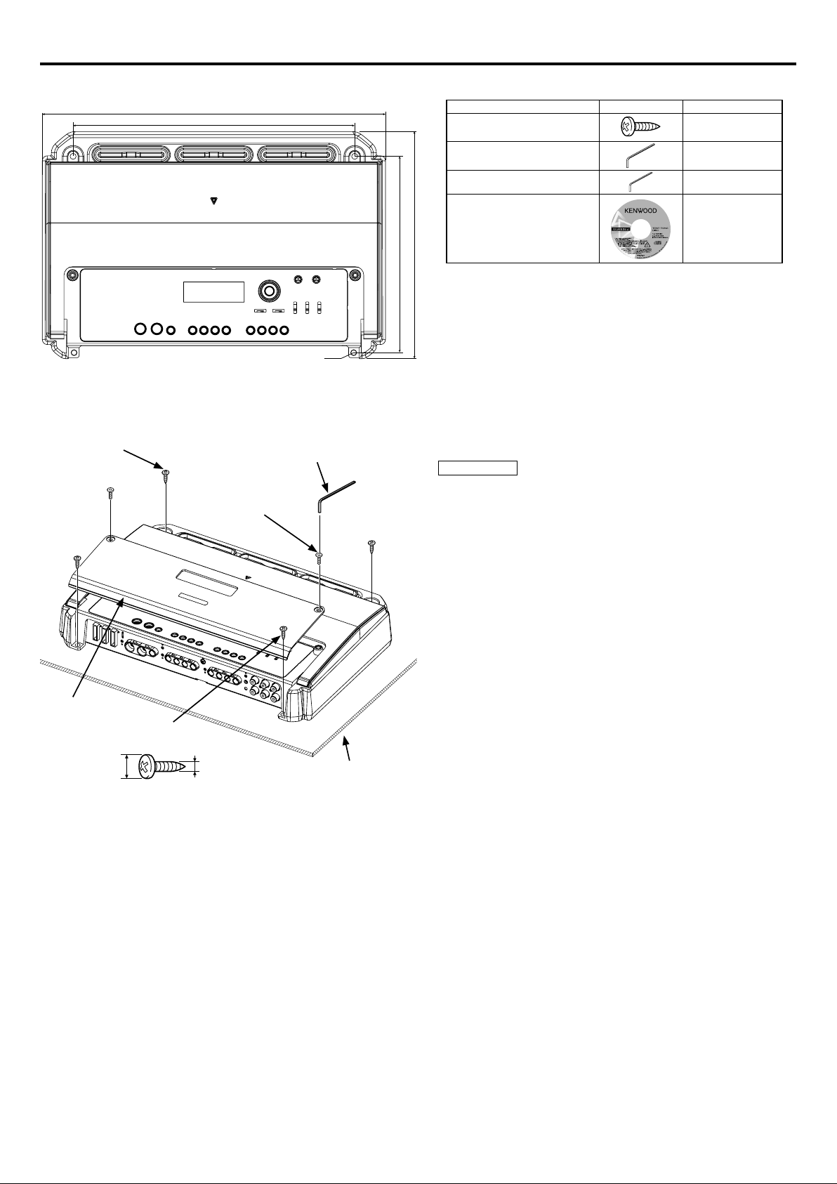
Installation
340 mm
279 mm
Accessories
Part name External View Number of Items
Self-tapping screws
(ø5 × 18 mm)
Hexagon Wrench (Large)
4
1
Self-tapping screw
(ø5 × 18 mm)
Dressing cover
ø7 – ø10 mm
Self-tapping screw
(ø5 × 18 mm)
Hexagon socket
head cap screw
(M4 × 8 mm)
ø5 mm
Ø6
Hexagon Wrench
(Small)
Installation board, etc.
(thickness : 15 mm or more)
Hexagon Wrench (Small)
Test tone Disc
225 mm
194.5 mm
Installation procedure
Since there are large variety of settings and connections possible according to
applications, read the instruction manual well to select the proper setting and
connection.
1. Remove the ignition key and disconnect the negative - terminal of the
battery to prevent short circuits.
2. Set the unit according to the intended usage.
3. Connect the input and output wires of the units.
4. Connect the speaker wires.
5. Connect the power wire, power control wire and grounding wire following this
order.
6. Install the installation fittings in the unit.
7. Attach the unit.
8. Connect the negative - terminal of the battery.
2CAUTION
• Do not install in the below locations;
(Unstable location, In a location that interferes with driving, In a location
that gets wet, In a dusty location, In a place that gets hot, In a place that
gets direct sunlight, In a location that gets hit by hot air)
• Do not install the unit under the carpet. Otherwise heat build-up occurs
and the unit may be damaged.
• Install this unit in a location which allows heat to easily dissipate.
Once installed, do not place any object on top of the unit.
• The surface temperature of the amplifier will become hot during use. Install
the amplifier in a place where people, resins, and other substances that are
sensitive to heat will not come into contact with it.
• This unit has cooling fan to decrease the internal temperature. Do not
mount the unit in a place where the cooling fan and ducts of the unit are
blocked. Blocking these openings will inhibit the cooling of the internal
temperature and result in malfunction.
• When making a hole under a seat, inside the trunk, or somewhere else in
the vehicle, check that there is nothing hazardous on the opposite side
such as a gasoline tank, brake pipe, or wiring harness, and be careful not to
cause scratches or other damage.
• Do not install near the dashboard, rear tray, or air bag safety parts.
• The installation to the vehicle should securely fasten the unit to a place in
which it will not obstruct driving. If the unit comes off due to a shock and
hits a person or safety part, it may cause injury or an accident.
• After installing the unit, check to make sure that electrical equipment
such as the brake lamps, turn signal lamps and windshield wipers operate
normally.
1
1
English 3
Page 4
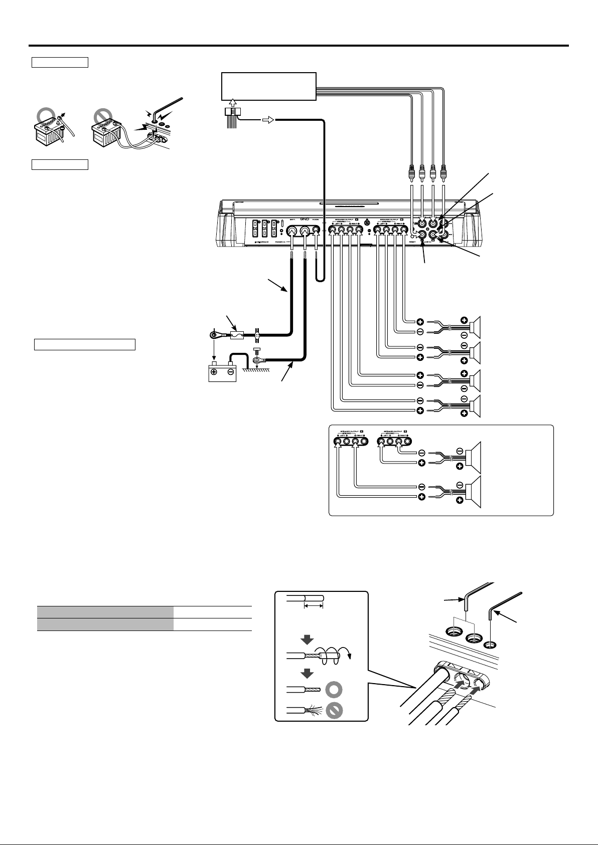
Connection
2WARNING
To prevent fire caused by a short in the wiring,
connect a fusible link or breaker nearby the
battery’s positive terminal.
CENTER UNIT
(CD receiver, etc.)
RCA cable*
2CAUTION
• If sound is not output normally, immediately
turn power off and check connections.
• Be sure to turn the power off before changing
the setting of any switch.
• If the fuse blows, check wires for shorts, then
replace the fuse with one of the same rating.
• Check that no unconnected wires or
connectors are touching the car body. Do
not remove caps from unconnected wires or
connectors to prevent short circuits.
• Connect the speaker wires to appropriate
speaker connectors separately. Sharing the
negative wire of the speaker or grounding
speaker wires to the metal body of the car can
cause this unit to fail.
• After installation, check that the brake lamps,
winkers, and wipers work properly.
* Commercially available parts
Battery wire*
Protective Fuse*
Battery
Power control wire
Ground wire*
Left input
Right input
B channel input
A channel input
B channel
Right speaker
B channel
Left speaker
A channel
Right speaker
A channel
Left speaker
■ Bridged Connections
About the Lead Terminals
Wire Thicknesses
1
You can use wires with the following thicknesses:
Battery wire and ground wire AWG 4 – AWG 8
Power control wire and speaker wire AWG 6 – AWG 18
2 Strip the wire
Make a cut in the wire sheath (insulator made from vinyl, etc.) at the
position 7-10 mm away from the end of the wire, and then remove
the unnecessary portion of the sheath by twisting it.
3 Install the wire
Loosen the screw using the supplied hexagon wrench.
Insert the conductor of the wire in the terminal hole, and then
tighten the screw.
7 – 10 mm
(9/32" – 3/8")
B channel
Speaker (Bridged)
A channel
Speaker (Bridged)
Hexagon Wrench
(Large)
Hexagon Wrench
(Small)
4 English
Page 5
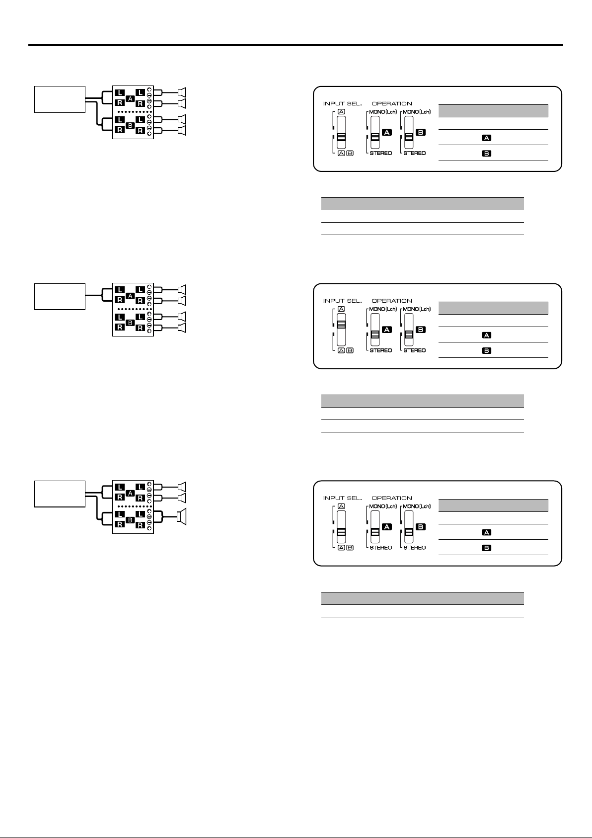
System examples
■ 4-channel system
CENTER UNIT
■ 2-channel system
CENTER UNIT
Front Left speaker
Front Right speaker
Rear Left speaker
Rear Right speaker
Left speaker (tweeter)
Right speaker (tweeter)
Left speaker (woofer)
Right speaker (woofer)
Switch Setting
INPUT SEL. AB
OPERATION
OPERATION
• DSP Settings (page 8)
Channel Setting Item Setting value
A ch HPF > FREQ TH(through)
B ch HPF > FREQ TH(through)
Switch Setting
INPUT SEL. A
OPERATION
OPERATION
STEREO
STEREO
STEREO
STEREO
■ 2-channel + Subwoofer system
CENTER UNIT
Left speaker (High pass)
Right speaker (High pass)
Subwoofer
(Bridged)
• DSP Settings (page 8)
Channel Setting Item Setting value
A ch HPF > FREQ 150 Hz
B ch LPF > FREQ 150 Hz
Switch Setting
INPUT SEL. AB
OPERATION
OPERATION
• DSP Settings (page 8)
Channel Setting Item Setting value
A ch HPF > FREQ 150 Hz
B ch LPF > FREQ 150 Hz
STEREO
STEREO
English 5
Page 6
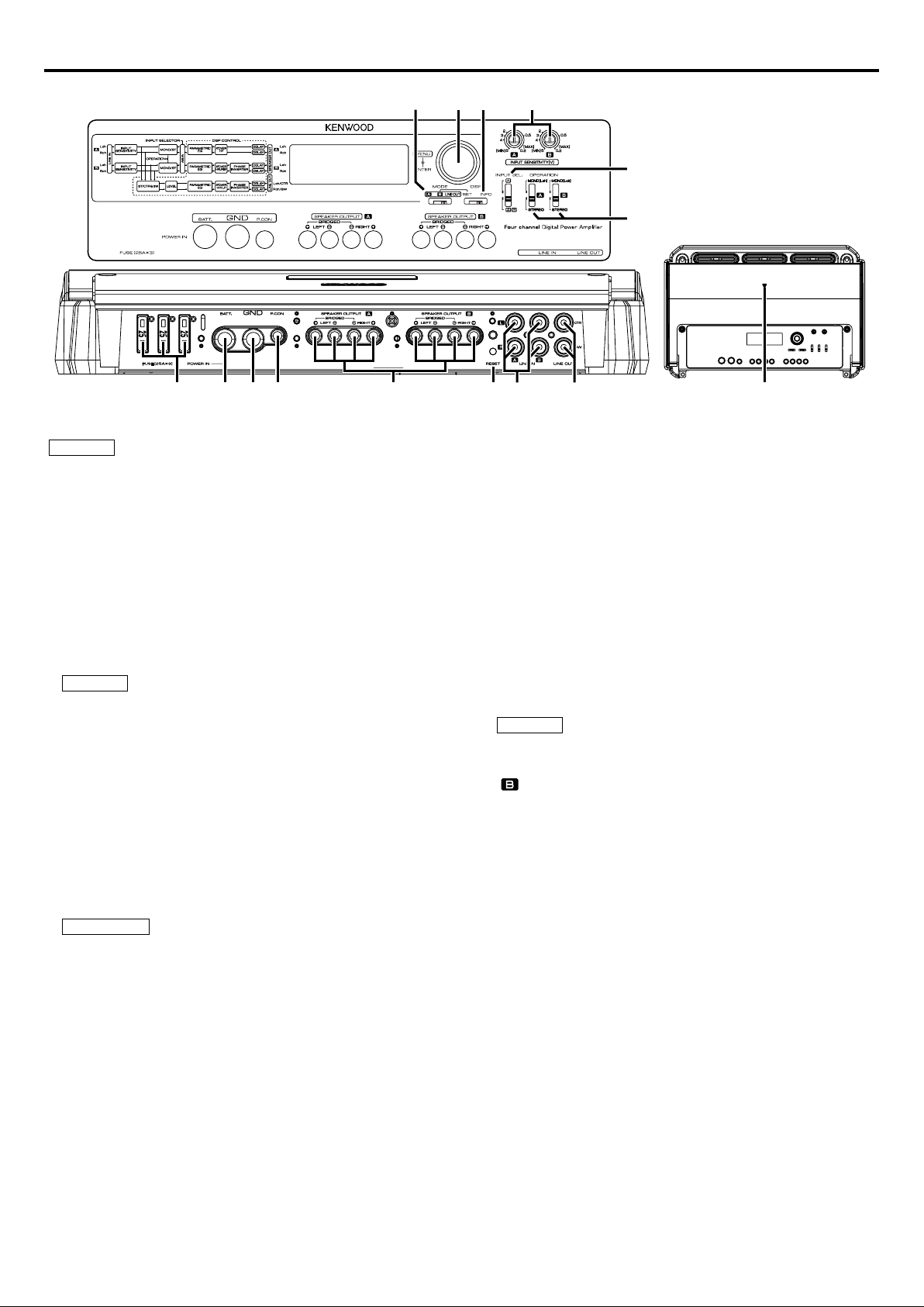
Controls
45321
NOTE
The control panel locates under the dressing cover. Remove the cover to
access to its controls for adjustment. (See page 3)
This is a 4 channel amplifier including 2 stereo amplifiers in a body. One
amplifier is referred to as amplifier A and the other is amplifier B. This unit
is compatible with a large variety of systems by combining the switches and
functions described in the following.
1 Fuse (25 A × 3)
2 Battery terminal
3 Ground terminal
4 Power control terminal
Controls the unit ON/OFF.
NOTE
Controls the unit power. Be sure to connect it with all the systems.
5 Speaker output terminals (A.ch/B.ch)
• Stereo Connections:
When you wish to use the unit as a stereo amplifier, stereo connections are
used.
The speakers to be connected should have an impedance of 2 or greater.
When multiple speakers are to be connected, ensure that the combined
impedance is 2 or greater for each channel.
• Bridged Connections:
When you wish to use the unit as a high-output monaural amplifier,
bridged connections are used. (Make connections to the LEFT channel 9
and the RIGHT channel · SPEAKER OUTPUT terminals.)
The speakers to be connected should have an impedance of 4 or greater.
When multiple speakers are to be connected, ensure that the combined
impedance is 4 or greater.
2CAUTION
The rated input of the speakers should be no less than the maximum output
of the amplifier. Otherwise malfunction may result.
6 RESET button
Resets the microprocessor of the unit.
7 LINE IN terminal
8 LINE OUT terminal
Outputs the audio signal set in DSP settings (stereo or center speaker/
subwoofer).
!0
@
#
$
%
96 78
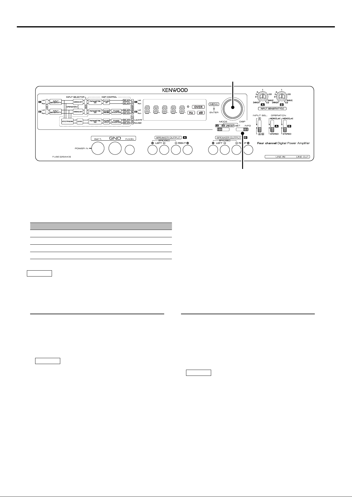
9 Power indicator
Lights when the POWER switch is turned On.
The indicator flashes several seconds when the POWER switch is turned On
or when the Protection function is activated.
0 MODE switch (A/B/LINE OUT)
This switch selects the channel set in DSP settings (A, B, LINE OUT).
! Control knob
Allows you to switch between and determine Menu System items.
@ DISP switch (SET/INFO)
• INFO position:
Sets <Status Information Display and Settings> (page 7).
• SET position:
Sets <DSP Settings> (page 8).
# INPUT SENSITIVITY control (A.ch/B.ch)
Set this control according to the pre-output level of the center unit
connected with this unit.
See <Input Sensitivity> (page 10) for details on setting.
NOTE
• For the LINE OUT level, refer to the <Specifications> in the instruction
manual of the center unit.
• When A is selected with the INPUT SELECTOR switch, the control portion for
cannot be used.
$ INPUT SELECTOR switch
This switch selects the input method of the signals to be amplified by
amplifiers A and B.
• A B position:
Amplifies both of the signals input to amplifiers A and B.
• A position:
Amplifies only the signal input to amplifier A with both amplifiers A and B.
% OPERATION switch (A.ch/B.ch)
The amplification methods of the signals input to amplifiers A and B can be
selected independently according to the setting of this switch.
• STEREO position:
The amplifier can be used as a stereo amplifier.
• MONO (Lch) position:
Amplifies the signal input from the left side only. Set to this position and
make bridged connections to use as a high-power monaural amplifier. (The
input right signal is not output.)
6 English
Page 7
Status Information Display and Settings
Displays the operating voltage, current consumption and internal temperature.
Additionally, changes the units for temperature or turns ON/OFF the demonstration.
Display type
Control knob
DISP switch
1 Slide the DISP switch towards INFO.
“INFO” appears on the display for 1 second.
2 Turn the control knob to change the display type in the following order.
Display Information / Function
“VOLT” Displays the operating voltage (V).
“CURRT” Displays the current consumption (A).
“TEMP” Displays the internal temperature (°C / °F).
“DEMO” Sets demonstration display ON / OFF.
NOTE
• Temperatures lower than -22°F or -30°C are displayed as “-22F” or “-30C” respectively.
• Displayed information may differ from actual conditions.
Changing the units for temperature
Select °F (Fahrenheit) or °C (Celsius).
1 Turn the control knob, display “TEMP” and push the
control knob.
2 Turn the control knob, display “---F” (Fahrenheit) or “---C”
(Celsius) and push the control knob.
NOTE
The default setting is “---F” (Fahrenheit).
Turning DEMO ON/OFF
Turn the demonstration function ON to display “VOLT”, “CURRT” and
“TEMP” information. The demonstration display changes every five
seconds.
1 Turn the control knob, display “DEMO” and push the
control knob.
2 Turn the control knob, display “ON” or “OFF” and push the
control knob.
NOTE
The default setting is “OFF”.
English 7
Page 8
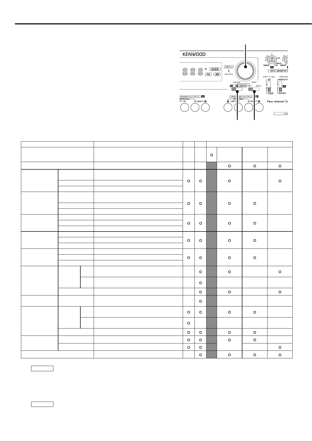
DSP Settings
Perform DSP settings for channels A, B and LINE OUT.
Setting
1 Slide the DISP switch towards SET.
2 Slide the MODE switch to set the channel (“Ach”, “Bch” or “LINE OUT”).
3 Turn the control knob, display the item to set and push the control knob.
Repeat this step until the item to set is displayed.
To return to the previous menu, turn the control knob, display “RTN” and press the
control knob.
4 Turn the control knob, display the value to set and press the control knob. The
displayed value is set.
Items and setting values
Item Setting value Ach Bch LINE OUT
LN.SEL ST / CT/SW (Default setting value : ST) × ×
LEVEL -20 – 0 (Default setting value : 0) × ×
FREQ (Hz)
BAND1
(Parametric EQ-1)
(Mean frequency)
Q 1.0/2.0/3.0/5.0 (Default setting value : 1.0)
GAIN -9 – +9 (Default setting value : 0)
BAND2
(Parametric EQ-2)
FREQ
Q 1.0/2.0/3.0/5.0 (Default setting value : 1.0)
GAIN -9 – +9 (Default setting value : 0)
BAND3
(Parametric EQ-3)
BAND4
(Parametric EQ-4)
BAND5
(Parametric EQ-5)
LPF
FREQ 600/800/1k/1.5k/2k (Default setting value : 600)
GAIN -9 – +9 (Default setting value : 0)
FREQ 3k/4k/5k/6.3k (Default setting value : 3k)
GAIN -9 – +9 (Default setting value : 0)
FREQ 8k/10k/12.5k/16k (Default setting value : 8k)
GAIN -9 – +9 (Default setting value : 0)
FREQ
(Low Pass Filter)
SLOPE −24/−12 (Default setting value : -12) × ×
ISF
(Infrasonic Filter)
HPF
FREQ
FREQ
(High Pass Filter)
SLOPE −24/−12 (Default setting value : -12) ×
DELAY
L 0 – 3.9 (Default setting value : 0)
R 0 – 3.9 (Default setting value : 0)
PHASE -180/0 (Default setting value : 0) ×
25/40/60/80/100 (Default setting value : 25)
150/200/300/400/500
(Default setting value : 150)
TH/30/40/50/60/70/80/90/100/120/150/180/220/
Low
250 (Default setting value : TH)
500/630/800/1k/1.25k/1.6k/2k/2.5k/3.15k/4k/5k
High
(Default setting value : TH)
TH/20/30/40/50/60
(Default setting value : TH)
TH/30/40/50/60/70/80/90/100/120/150/180/220/
Low
250 (Default setting value : TH)
500/630/800/1k/1.25k/1.6k/2k/2.5k/3.15k/4k/5k
High
(Default setting value : TH)
Control knob
DISP switchMODE switch
ST
(When LN.SEL. is
set to “ST”)
CTR
(When LN.SEL. is
set to “CT/SW”)
SW
(When LN.SEL. is
set to “CT/SW”)
×
×
×Q 1.0/2.0/3.0/5.0 (Default setting value : 1.0)
×Q 2.0/4.0/8.0/10 (Default setting value : 2.0)
×Q 2.0/4.0/8.0/10 (Default setting value : 2.0)
×
×
×××
×
× ×××
×
× ×××
×
(L/R is not
differentiated)
×
8 English
NOTE
• For LPF, HPF must be set to “TH”.
• For ISF, HPF must be set to “TH”.
• For HPF, LPF and ISF must be set to “TH”.
• If LPF and ISF are set simultaneously, LPF frequency cannot be lower than ISF frequency.
NOTE
• If speakers are bridged, set “L” and “R” for “DELAY” to the same value. Effects will not be applied properly if they are set to different values.
• DSP settings will not be cleared even when the reset button is pressed.
Page 9
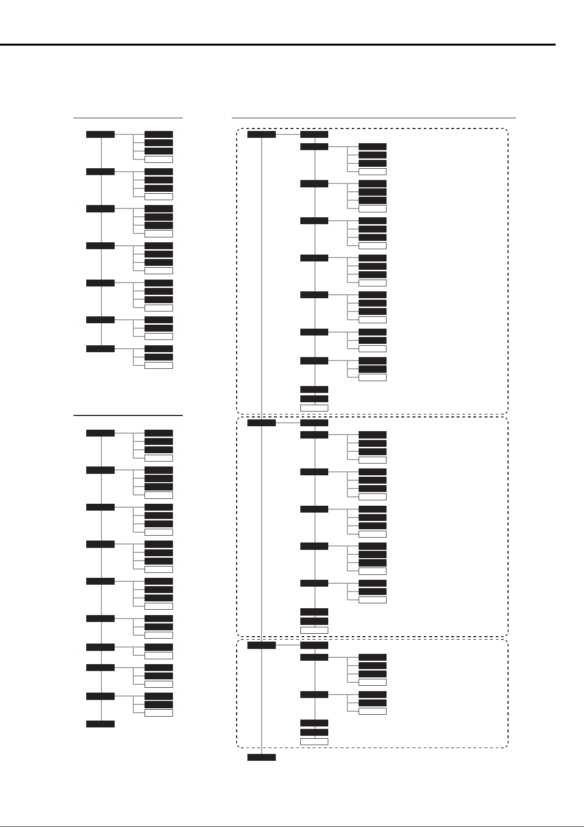
DSP settings menu list
See <Items and setting values> (page 8) for setting values.
■ Ach setting menu ■ LINE OUT setting menu
BAND1 FREQ
BAND2
BAND3
BAND4
BAND5
HPF
DELAY L
Q
GAIN
RTN
FREQ
Q
GAIN
RTN
FREQ
Q
GAIN
RTN
FREQ
Q
GAIN
RTN
FREQ
Q
GAIN
RTN
FREQ
SLOPE
RTN
R
RTN
■ Bch setting menu
BAND1 FREQ
BAND2
BAND3
BAND4
BAND5
LPF FREQ
HPF
DELAY L
PHASE
Q
GAIN
RTN
FREQ
Q
GAIN
RTN
FREQ
Q
GAIN
RTN
FREQ
Q
GAIN
RTN
FREQ
Q
GAIN
RTN
SLOPE
RTN
FREQISF
RTN
FREQ
SLOPE
RTN
R
RTN
CTR
SW
LN.SEL
LEVELST
BAND1 FREQ
BAND2
BAND3
BAND4
BAND5
LPF FREQ
HPF
DELAY
PHASE
RTN
LEVEL
BAND2
BAND3
BAND4
BAND5
HPF
DELAY
PHASE
RTN
LEVEL
BAND1
LPF
DELAY
PHASE
RTN
Q
GAIN
RTN
FREQ
Q
GAIN
RTN
FREQ
Q
GAIN
RTN
FREQ
Q
GAIN
RTN
FREQ
Q
GAIN
RTN
SLOPE
RTN
FREQ
SLOPE
RTN
FREQ
Q
GAIN
RTN
FREQ
Q
GAIN
RTN
FREQ
Q
GAIN
RTN
FREQ
Q
GAIN
RTN
FREQ
SLOPE
RTN
FREQ
Q
GAIN
RTN
FREQ
SLOPE
RTN
Stereo output settings
(When LN.SEL is set to ST )
Center output settings
(When LN.SEL is set to CT/SW)
Subwoofer output settings
(When LN.SEL is set to CT/SW)
English 9
Page 10
Input Sensitivity
This amplifier features a digital signal processor (DSP).
By processing signals digitally, finer equalization and filtering
are possible.
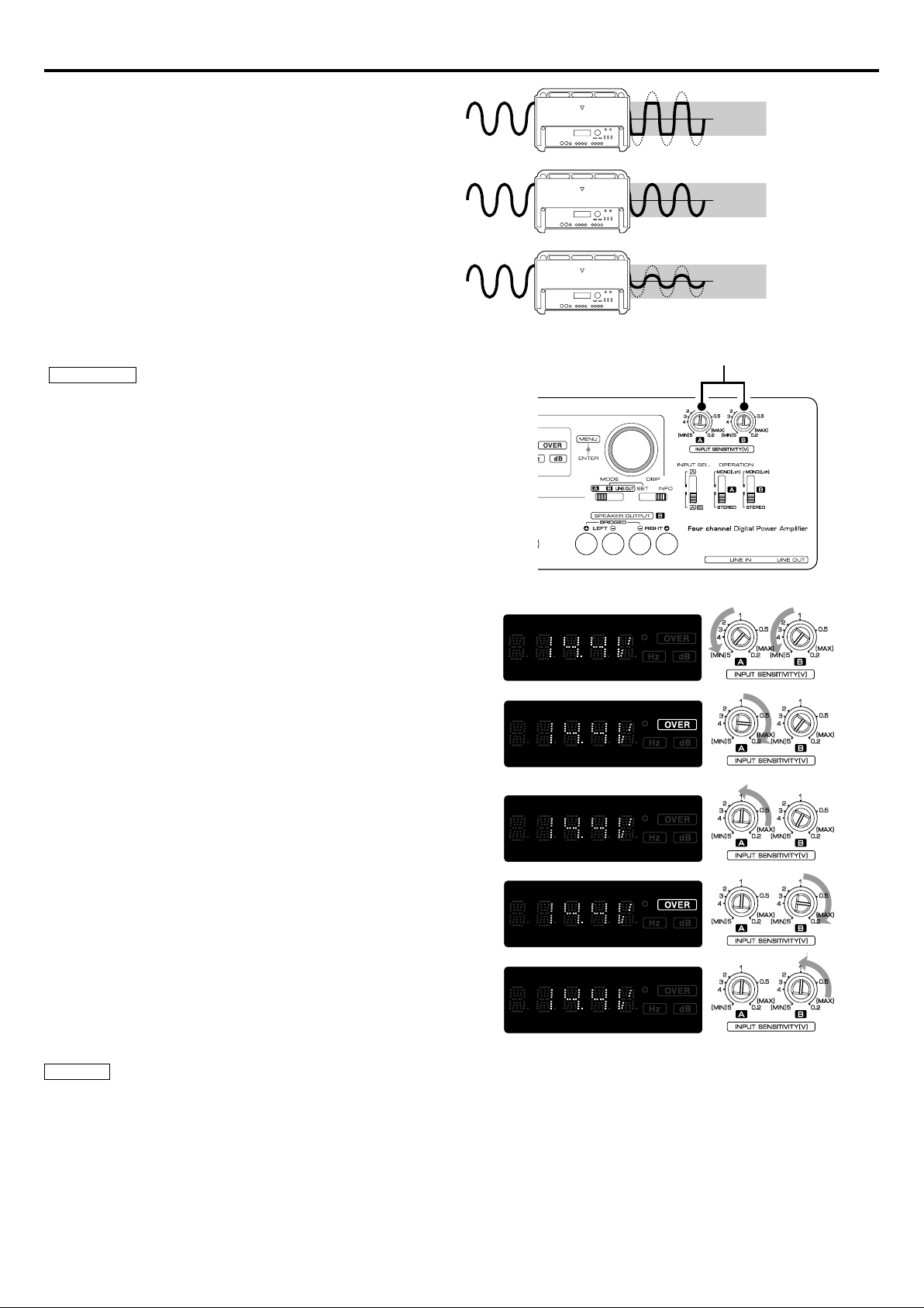
Input sensitivity is important to efficiently convert analog
signals to digital signals. If the input signal is too high, sound
is distorted. If it is too soft, sound quality deteriorates.
High input
sensitivity
Conversion
range
Over
Optimum
sensitivity
Low input
sensitivity
Adjusting input sensitivity
2CAUTION
• Be sure to disconnect speakers before adjusting input sensitivity.
• The test disc includes high volume test signals. Speakers may be damaged if input
sensitivity is adjusted while connected.
• Do not use the test disc for purposes other than adjusting input sensitivity.
1 Disconnect the speakers.
2 Turn the audio system on.
3 Playback Track 2 in Test tone Disc with a CD receiver or other device.
Track 2 is 3 minutes long.
4 Set the device to the loudest volume you listen to.
For example, if this volume is approximately 80% of the maximum volume, the
volume is 30 on a device where volume can be set between 0 and 35.
5 Turn the input sensitivity control counterclockwise and set A.ch and B.ch to
MIN.
Conversion
range
Conversion
range
Input sensitivity control
Optimum
Conversion range
is not fully utilized
6 Turn the input sensitivity control for A.ch clockwise (towards MAX) until the
“OVER” indicator lights.
7 Slowly turn the input sensitivity control for A.ch counterclockwise (towards
MIN) until the “OVER” indicator turns off.
8 Turn the input sensitivity control for B.ch clockwise (towards MAX) until the
“OVER” indicator lights.
9 Slowly turn the input sensitivity control for B.ch counterclockwise (towards
MIN) until the “OVER” indicator turns off.
The setting where the “OVER” indicator turns off for A.ch and B.ch is the optimum
input sensitivity.
10 Turn the audio system off and connect the speakers.
NOTE
• To fine tune while listening to music
- If there is not enough volume: Turn the input sensitivity control clockwise
(towards MAX).
- If there is too much volume: Turn the input sensitivity control counterclockwise
(towards MIN).
Contents of the Test tone Disc
Track 1: Warning announcement (English and Japanese) 10 minutes
Track 2: Test tone (Sinusoidal-wave, 100 Hz, 0 dB) 3 minutes
10 English
Page 11

Troubleshooting Guide
What might appear to be a malfunction in your unit may just be the result of slight misoperation or miswiring. Before calling service, first check the following
table for possible problems.
PROBLEM POSSIBLE CAUSE SOLUTION
No sound.
(Blown fuse.)
The output level is too small
(or too large).
The sound quality is bad.
(The sound is distorted.)
• Input (or output) cables are disconnected.
• Protection circuit may be activated.
• Volume is too high.
• The speaker cord is shorted.
• The input sensitivity adjusting control is not set to the correct
position.
• The speakers wire are connected with wrong + /-polarity.
• A speaker wire is pinched by a screw in the car body.
• The switches may be set improperly.
• The “OVER” indicator is lit.
• Connect the input (or output) cables.
• Check connections by referring to <Protection function>.
• Replace the fuse and use lower volume.
• After check the speaker cord and fixing the cause of the short,
replace the fuse.
• Adjust the control correctly referring to <Input Sensitivity>.
• Connect them properly checking the + / - of the terminals
and wires well.
• Connect the speaker wire again so that it is not pinched by
anything.
• Set switches properly by referring to <Controls> or <DSP
Settings>.
• Input level is too high. See <Input Sensitivity> and adjust.
Specifications
Specifications subject to change without notice.
CEA-2006
RMS Watts per channel @ 4 ohms, 1 % THD+N .......................................................................................................................................................................100 W × 4
Signal to Noise Ratio (Reference: 1Watt into 4 ohms) ................................................................................................................................................................ 78 dBA
Audio Section
Max Power Output .........................................................................................................................................................................................................................................1200 W
Rated Power Output (+B = 12.0 V)
(4 ) (20 Hz – 20 kHz, 0.8 % THD) ....................................................................................................................................................................................... 75 W × 4
(2 ) (1 kHz, 1.0 % THD) ..........................................................................................................................................................................................................100 W × 4
(Bridged 4 ) (1 kHz, 1.0 % THD) ..................................................................................................................................................................................... 200 W × 2
Rated Power Output (+B = 14.4 V)
(4 ) (20 Hz – 20 kHz, 0.8 % THD) .....................................................................................................................................................................................100 W × 4
(4 ) (DIN45324, +B = 14.4 V) .............................................................................................................................................................................................100 W × 4
(2 ) (1 kHz, 1.0 % THD) ..........................................................................................................................................................................................................150 W × 4
(Bridged 4 ) (1 kHz, 1.0 % THD) .......................................................................................................................................................................................300 W × 2
Frequency Response (+0, -1 dB) ............................................................................................................................................................................................ 20 Hz – 20 kHz
Sensitivity (rated output) (MAX.) .................................................................................................................................................................................................................0.2 V
Sensitivity (rated output) (MIN.) ..................................................................................................................................................................................................................5.0 V
Input Impedance ............................................................................................................................................................................................................................................... 10 k
Signal to Noise Ratio ......................................................................................................................................................................................................................................105 dB
Low Pass Filter Frequency (-24 / -12 dB/oct.)
Low Range .................................................................................................................................................................................................................................30 – 250 Hz
High Range ............................................................................................................................................................................................................................... 500 – 5k Hz
High Pass Filter Frequency (-24 / -12 dB/oct.)
Low Range .................................................................................................................................................................................................................................30 – 250 Hz
High Range ............................................................................................................................................................................................................................... 500 – 5k Hz
Infrasonic Filter Frequency (-24 dB/oct.) ........................................................................................................................................................20 / 30 / 40 / 50 / 60 Hz
Built in Parametric EQ Control
Frequency BAND 1 ...................................................................................................................................................................................25 / 40 / 60 / 80 / 100 Hz
Frequency BAND 2 ........................................................................................................................................................................150 / 200 / 300 / 400 / 500 Hz
Frequency BAND 3 ......................................................................................................................................................................... 600 / 800 / 1 k / 1.5 k / 2 k Hz
Frequency BAND 4 ........................................................................................................................................................................................3 k / 4 k / 5 k / 6.3 k Hz
Frequency BAND 5 ................................................................................................................................................................................8 k / 10 k / 12.5 k / 16 k Hz
Quality Factor BAND 1 – BAND3 ......................................................................................................................................................................1.0 / 2.0 / 3.0 / 5.0
Quality Factor BAND 4 – BAND5 .......................................................................................................................................................................2.0 / 4.0 / 8.0 / 10
Gain (Boost or Cut) ............................................................................................................................................................................................................-9 dB – +9 dB
Delay Control ........................................................................................................................................................................................................0 ms – 3.9 ms (0.1 ms Step)
Phase Inverter .....................................................................................................................................................................................................0° (Normal) / -180° (Reverse)
General
Operating Voltage .............................................................................................................................................................................................. 14.4 V (11 – 16 V allowable)
Current Consumption ........................................................................................................................................................................................................................................60 A
Installation Size (W × H × D) .........................................................................................................................................................................................340 × 60 × 225 mm
..................................................................................................................................................................................................................1213-3/8 × 2-3/8 × 8-7/8 inch
Weight ...................................................................................................................................................................................................................................................3.8 kg (8.4 lbs)
Weight ..................................................................................................................................................................................................................................................................................
English 11
Page 12

Précautions de sécurité
2AVERTISSEMENT
Pour éviter toute blessure et/ou incendie, veuillez prendre les
précautions suivantes:
• Le montage et le câblage de ce produit nécessite des compétences et de
l'expérience. Pour des raisons de sécurité, laissez un professionnel effectuer le
travail de montage et de câblage.
• Si vous prolongez un câble de batterie ou de masse, assurez vous d'utiliser un
câble pour automobile ou un câble compris entre 10 mm (AWG 8) et 25 mm
(AWG 4) afin d'éviter tout risque de détérioration ou d'endommagement du
revêtement des câbles.
• Pour éviter les court-circuits, ne jamais mettre ou laisser d'objets métalliques
(comme une pièce de monnaie ou un outil en métal) à l'intérieur de l'appareil.
• Si l'appareil commence à émettre de la fumée ou une odeur bizarre, mettez
immédiatement l'appareil hors tension et consultez un revendeur Kenwood.
• Ne pas toucher l’appareil quand il est en service car la température de sa
surface est suffisamment élevée pour provoquer des brûlures.
2ATTENTION
Pour éviter tout dommage à l'appareil, veuillez prendre les
précautions suivantes:
• Bien vérifier que l’appareil est raccordé à une source d’alimentation CC de 12 V
avec raccordement de masse négative.
• N'ouvrez pas le couvercle supérieur ou inférieur de l'appareil.
• N'installez pas l'appareil dans un endroit exposé directement à la lumière du
soleil, à une chaleur excessive ou à l'humidité. Évitez aussi les endroits trop
poussiéreux et où l'appareil risque d'être éclaboussé.
• Lors du remplacement d'un fusible, utilisez seulement un fusible neuf avec la
valeur indiquée. L'utilisation d'un fusible d'une valeur différente peut être la
cause d'un mauvais fonctionnement de votre appareil.
• Pour éviter les courts-circuits lors du remplacement d'un fusible, déconnectez
d'abord le faisceau de câbles.
REMARQUE
• Si vous rencontrez des problèmes pendant l'installation, consultez votre
revendeur Kenwood.
• Si l'appareil semble ne pas fonctionner correctement, consultez votre
revendeur Kenwood.
• Un traitement numérique se produit à l'intérieur de cet amplificateur. C'est
pourquoi il est possible qu'un léger délai se produise lorsqu'il est utilisé en
conjonction avec d'autres amplificateurs. Si ceci se produit, branchez l'audio
de pré-sortie de cet amplificateur sur l'autre amplificateur.
REMARQUE
Cet appareil numérique de la classe B est conforme à la morme NMB-003 du
Canada.
Information sur l’élimination des anciens équipements
électriques et électroniques (applicable dans les pays de l’Union
Européenne qui ont adopté des systèmes de collecte sélective)
Les produits sur lesquels le pictogramme (poubelle barrée) est apposé
ne peuvent pas être éliminés comme ordures ménagères.
Les anciens équipements électriques et électroniques doivent être
recyclés sur des sites capables de traiter ces produits et leurs déchets.
Contactez vos autorités locales pour connaître le site de recyclage le
plus proche. Un recyclage adapté et l’élimination des déchets aideront
à conserver les ressources et à nous préserver des leurs effets nocifs
sur notre santé et sur l’environnement.
Ce produit n’est pas installé par le constructeur d’un véhicule sur le site de
production, ni par l’importateur professionnel d’un véhicule dans un Etat
membre de l’UE.
Nettoyage de l’appareil
Si la surface de l’appareil devient sale, l’essuyer avec un chiffon au silicone ou un
chiffon doux et sec après avoir éteint l’appareil.
2ATTENTION
N'essuyez pas le panneau avec un tissu rugueux ou imprégné de dissolvant
volatile comme un diluant à peinture ou de l'alcool. Il pourrait rayer la surface
du panneau et/ou écailler les lettres d'information.
Comment éviter une élévation de la batterie
Lorsque l’unité est utilisée avec l’ACC sur ON, sans que le moteur ne soit allumé,
cela décharge la batterie. Il est préférable de l’utiliser après avoir allumé le
moteur.
Fonction de protection
L’unité dispose d’une fonction de protection destinée à la protéger, ainsi que
les enceintes, contre différents dysfonctionnements. Lorsque la protection
fonctionne, l’affichage vous informe de l’état.
Affichage Information
"E-01" Lorsque l’intérieur de l’unité est en surchauffe.
Lorsque l’unité est en panne et que l’intensité du courant continu est transmise à la
sortie d'enceinte.
"E-02"
"E-03"
"E-99"
L’affichage "VOLT"
clignote.
REMARQUE
Eteindre l’appareil puis ôter la protection. Si le code "E-02" ne disparaît pas, consultez
la station technique la plus proche.
Lorsque le cordon de l'enceinte est en court-circuit.
Lorsque la sortie d'enceinte est en contact avec la masse du véhicule.
Lorsqu'une erreur système se produit.
Appuyez sur la touche de réinitialisation. Si le code "E-99" ne disparaît pas, consultez
la station technique la plus proche.
Lorsque la valeur de la tension est en dehors des limites de fonctionnement.
Câblage
• Pour cette unité, brancher le cordon de la batterie directement à la batterie. Si
celui-ci est connecté à l’installation électrique du véhicule, l’installation peut
disjoncter etc.
• Si un ronronnement se fait entendre dans les enceintes lorsque le moteur
tourne, fixer un filtre antiparasite de ligne (en option) aux câbles de la batterie.
• Utiliser un passe-câble de manière que le cordon ne soit pas en contact avec
le tablier.
• Relier les fils de masse à une partie métallique du châssis du véhicule qui soit
en mesure de jouer le rôle de masse électrique et donc de laisser passer le
courant vers le pôle négatif - de la batterie. Ne pas mettre l’appareil sous
tension si les fils de masse ne sont pas reliés.
• Assurez-vous de mettre en place un fusible protégeant le cordon
d’alimentation situé près de la batterie. Ce fusible doit avoir un pouvoir de
coupure égal ou légèrement supérieur à celui de l’unité.
• En ce qui concerne le cordon d’alimentation et la masse, il est conseillé
d’utiliser un cordon d’alimentation électrique pour voiture (ininflammable)
dont l’intensité sera supérieure au pouvoir de coupure du fusible de l’unité.
(Utiliser un cordon d’alimentation d’un diamètre compris entre 10 mm (AWG
8) et 25 mm (AWG 4)).
• Lorsque plus d’un amplificateur de puissance doivent être utilisés, utiliser
un câble de câblage d’alimentation et un fusible de sécurité dont la limite
de tension est supérieure au courant total maximum tiré par chaque
amplificateur.
Sélection des enceintes
• La puissance d’entrée nominale des enceintes qui vont être connectées doit
être supérieure à la puissance de sortie maximum (en Watts) de l’amplificateur.
L’utilisation d'enceintes dont la puissance d’entrée nominale est inférieure à la
puissance de sortie de l’amplificateur entraînera l’émission de fumée, ainsi que
des dommages.
• L’impédance des enceintes qui vont être connectées doit être de 2
minimum (pour des connexions stéréo) ou de 4 minimum (pour des
connexions en pont). Lorsque plus d’un jeu d'enceintes va être utilisé, calculer
l’impédance combinée des enceintes et connecter ensuite les enceintes
appropriées à l’amplificateur.
12 Français
4Ω
4Ω
8 Ω
Impédance combinée
4Ω 4Ω
2 Ω
Page 13

Installation
340 mm
279 mm
Accessoires
Nom de la pièce Vue extérieure Quantité
Vis auto-taraudeuses (ø5 × 18
mm)
Clé polygonale (grand)
4
1
Vis auto-taraudeuse
(ø 5 × 18 mm)
Enjoliveur
ø7 – ø10 mm
Vis auto-taraudeuse
(ø 5 × 18 mm)
Vis d’assemblage à
six pans creux
(M4 × 8 mm)
ø5 mm
Ø6
Clé polygonale
(petite)
Tableau d'installation, etc.
(épaisseur: 15 mm ou plus)
Clé polygonale (petite)
Disque de tonalité de test
225 mm
194.5 mm
Procédure d'installation
Étant donné que le nombre de réglages et de raccordements est assez
important, il importe de prendre pleinement connaissance du mode d'emploi.
1. Retirer la clé de contact et débrancher la borne négative - de la batterie pour
éviter les court-circuits.
2. Régler l'appareil en fonction de l'utilisation désirée.
3. Raccorder les câbles d’entrée et de sortie de l’appareil.
4. Raccorder les câbles d'enceinte.
5. Relier, dans l'ordre, le câble d'alimentation, le câble de commande
d'alimentation et le câble de masse.
6. Mettre en place les accessoires d’installation sur l’unité.
7. Brancher l’unité.
8. Raccorder la borne négative - de la batterie.
2ATTENTION
• Ne pas procéder à l’installation de l’appareil si vous vous trouvez dans l’un
des lieux suivants;
(Lieu instable, Lieu où la conduite du véhicule peut être gênée, Lieu exposé
à l’humidité, Lieu exposé à la poussière, Lieu surchauffé, Lieu exposé
directement à la lumière du jour, Lieu exposé à l’air chaud)
• Ne pas recouvrir l’appareil d’une nappe, tapis, etc; la chaleur qui
s’accumulerait risque d’endommager l’appareil.
• Installer cet appareil à un emplacement tel que la chaleur puisse se dissiper
aisément.
Après l’installation, ne placer aucun objet sur l’appareil.
• La surface de l’amplificateur va chauffer pendant l’utilisation. Installer
l’amplificateur à un endroit où des passagers, de la résine ou d’autres
substances sensibles à la chaleur n’entreront pas en contact avec lui.
• Cette unité dispose d’un ventilateur de refroidissement permettant
d’abaisser la température interne. Ne pas monter l’unité dans un endroit où
le ventilateur de refroidissement et les conduites de l’unité sont bloquées.
En effet, si la chaleur interne ne peut pas être éliminée par la ventilation de
l'appareil, une anomalie de fonctionnement peut aisément survenir.
• Lors du forage d’un trou sous le siège, à l’intérieur du coffre ou partout
ailleurs dans le véhicule, vérifier s’il n’y a pas d’élément dangereux de l’autre
côté, tel qu’un réservoir à carburant, une conduite de frein, une gaine de
câbles, et faire attention de ne pas faire de griffes ou d’autres dégâts.
• Ne pas l’installer près du tableau de bord, de la plage arrière ou d’éléments
de sécurité de l’airbag.
• Lors de l’installation dans un véhicule, l’appareil doit être fermement fixé à
un endroit ou il ne gênera pas la conduite. Si l’appareil se détache suite à
un choc et heurte quelqu’un ou un élément de sécurité, il peut occasionner
des blessures ou un accident.
• Après installation de l’appareil, s’assurer que les différents équipements
électriques tels que lampes de frein et les clignotants de direction
fonctionnent normalement.
1
1
Français 13
Page 14

Raccordements
2AVERTISSEMENT
Pour éviter tout incendie dû à un court-circuit,
insérez un fusible ou un coupe-circuit à
proximité de la borne de la batterie.
Unité centrale
(lecteur de CD, etc.)
Câble RCA*
2ATTENTION
• En cas d'anomalie, mettez immédiatement
l'appareil hors tension et vérifiez tous les
raccordements.
• Veillez à mettre l'appareil hors tension avant
de changer la position des commutateurs.
• Si le fusible saute, vérifiez si les câbles ne sont
pas court-circuités, et remplacez le fusible par
un autre fusible de même capacité nominale.
• Vérifiez qu’aucun câble ou connecteur non
raccordé ne touche la carrosserie de la voiture.
Ne pas retirer les capuchons des câbles ou
connecteurs non raccordés afin d’éviter tout
court-circuit.
• Raccordez séparément les câbles d'enceinte
aux connecteurs d'enceinte appropriés. Le
partage du câble négatif d’une enceinte ou
des fils de masse des enceintes à la carrosserie
métallique de la voiture pourrait rendre
l’appareil inopérant.
• Après l’installation, vérifier que les voyants
de frein, les clignotants et les essuie-glace
fonctionnent correctement.
* disponible dans le commerce
Câble de commande
de l’alimentation
Câble de la batterie*
Fusible de protection*
Batterie
Câble de masse*
Entrée de la voie gauche
Entrée de la
voie droite
Entrée canal B
Entrée canal A
Canal B
Enceinte droite
Canal B
Enceinte gauche
Canal A
Enceinte droite
Canal A
Enceinte gauche
■ Connexions en pont
À propos des bornes de câble
Épaisseurs des câbles
1
Vous pouvez utiliser des câbles aux épaisseurs suivantes :
Câble de batterie et câble de masse AWG 4 – AWG 8
Câble de commande de
l'alimentation et câble d'enceinte
AWG 6 – AWG 18
2 Dénuder le câble
Coupez la gaine du câble (isolant en vinyle, etc.) à environ 7-10 mm
de l'extrémité du câble, puis enlevez la portion de gaine inutile en la
faisant tourner dans vos doigts.
3 Installer le câble
Desserrez la vis à l'aide de la clé hexagonale fournie.
Insérez le fil conducteur du câble dans l'orifice de la borne, puis
serrez la vis.
7 – 10 mm
(9/32" – 3/8")
Canal B
Enceinte (Pont)
Canal A
Enceinte (Pont)
Clé polygonale
(grand)
Clé polygonale
(petite)
14 Français
Page 15

Exemples de configuration
■ Système 4 voies
Unité centrale
■ Système 2 voies
Unité centrale
Enceinte avant gauche
Enceinte avant droite
Enceinte arrière gauche
Enceinte arrière droite
Enceinte gauche (haut-parleur d'aigus)
Enceinte droite (haut-parleur d'aigus)
Enceinte gauche (haut-parleur de graves)
Enceinte droitpdf (haut-parleur de graves)
Interrupteur Réglage
INPUT SEL. AB
OPERATION
OPERATION
• Réglages DSP (page 18)
Canal Élément à régler Valeur à régler
A ch HPF > FREQ TH (Aucun)
B ch HPF > FREQ TH (Aucun)
Interrupteur Réglage
INPUT SEL. A
OPERATION
OPERATION
STEREO
STEREO
STEREO
STEREO
■ Système 2 voies + enceinte d'extrêmes graves
Unité centrale
Enceinte gauche (filtre passe-haut)
Enceinte droite (filtre passe-haut)
Enceintes d'extrêmes graves
(Pont)
• Réglages DSP (page 18)
Canal Élément à régler Valeur à régler
A ch HPF > FREQ 150 Hz
B ch LPF > FREQ 150 Hz
Interrupteur Réglage
INPUT SEL. AB
OPERATION
OPERATION
• Réglages DSP (page 18)
Canal Élément à régler Valeur à régler
A ch HPF > FREQ 150 Hz
B ch LPF > FREQ 150 Hz
STEREO
STEREO
Français 15
Page 16

Contrôles
45321
REMARQUE
Le panneau de commande se situe sous l’enjoliveur. Retirez le couvercle pour
accéder aux commandes de réglage. (Voir page 13)
Ceci est un amplificateur à 4 canaux avec deux amplificateurs
stéréophoniques en un élément; l’un appelé Amplificateur A, l’autre
Amplificateur B. Cet appareil est compatible avec diverses systèmes,
simplement en sélectionnant les positions des commutateurs et les
fonctions comme indiqué ci-après.
1 FUSIBLE (25 A × 3)
2 Borne BATT (alimentation)
3 Borne GND (masse)
4 Borne P.CON (fil de commande d’alimentation)
Commande l’unité ON/OFF.
REMARQUE
Commande l’unité d’alimentation. Assurez-vous de le connecter à l’ensemble
des différents systèmes.
5 Bornes SPEAKER OUTPUT (A.ch/B.ch)
• Connexions stéréo:
Pour utiliser l’appareil comme amplificateur stéréo, des connections stéréo
doivent être utilisées.
Les enceintes à connecter doivent avoir une impédance de 2 ou
supérieure. Lorsque plusieurs enceintes doivent être connectées, s’assurer
que l’impédance combinée soit de 2 ou supérieure pour chaque canal.
• Connexions en pont:
Pour l’utilisation de l’appareil comme amplificateur monophonique à haute
puissance de sortie, des connections en pont doivent être utilisées. (Faire
les connexions aux bornes SPEAKER OUTPUT du canal gauche (LEFT) 9 et
du canal droit (RIGHT) ·.)
Les enceintes à connecter doivent avoir une impédance de 4 ou
supérieure. Lorsque plusieurs enceintes doivent être connectées, s’assurer
que l’impédance combinée soit de 4 ou supérieure.
2ATTENTION
La puissance admissible par les enceintes doit être au moins égale à la
puissance de sortie de l'amplificateur. Dans le cas contraire, une anomalie de
fonctionnement peut survenir.
6 Touche RESET
Réinitialise le microprocesseur de l’unité.
7 Borne d'entrée de ligne (LINE IN)
8 Sortie de ligne (LINE OUT)
Émet le signal audio configuré dans le réglage DSP (stéréo ou enceinte
centrale/subwoofer).
!0
@
#
$
%
96 78
9 Indicateur Power
S’allume lorsque le commutateur POWER est mis en marche.
Le voyant clignote pendant plusieurs secondes lorsque le commutateur
POWER est mis en marche ou lorsque la fonction de protection est activée.
0 Interrupteur de MODE (A/B/LINE OUT)
Cet interrupteur permet de sélectionner le canal configuré dans les réglages
DSP (A, B, LINE OUT).
! Molette de commande
Vous permet de passer d'un élément du système de menu à l'autre et de les
déterminer.
@ Interrupteur DISP (SET/INFO)
• Position INFO :
Permet de configurer <Affichage et réglages de l'information d'état> (page
17).
• Position SET :
Permet de configurer les <Réglages DSP> (page 18).
# Commande INPUT SENSITIVITY (Sensibilité d'entrée) (A
/ B)
Réglez cette commande selon le niveau de pré-sortie de l’unité centrale
branché à cet amplificateur.
Reportez-vous à la section <Sensibilité d'entrée> (page 20) pour les détails
de réglage.
REMARQUE
• Pour le niveau LINE OUT, reportez-vous à la section <Spécifications> du
manuel d'instructions de l'unité centrale.
• Quand A est sélectionné avec l'interrupteur INPUT SELECTOR (sélecteur
d'entrée), la section des commandes pour ne peut pas être utilisée.
$ Commutateur INPUT SELECTOR (Sélecteur d'entrée)
Ce sélecteur permet de choisir le mode d'amplification des signaux par les
amplificateurs A et B.
• Position A B:
Les signaux d'entrée des amplificateurs A et B sont tous deux amplifies.
• Position A:
Amplifie uniquement l'entrée de signal à l'amplificateur A avec les deux
amplificateurs A et B.
% Interrupteur OPERATION (A / B)
Selon la position de ce commutateur, le signal appliqué aux amplificateurs A
et B peut être soumis à une méthode d’amplification différente.
• Position STEREO:
L'amplificateur peut être utilisé en tant qu'amplificateur stéréo.
• Position MONO(Lch):
Seul le signal présent à l’entrée de la voie gauche est amplifié. Utilisez
cette position et effectuez les connexions en pont pour disposer d’un
amplificateur monaural de plus forte puissance. (Le signal d'entrée droite
n'est pas reproduit.)
16 Français
Page 17

Affichage et réglages de l'information d'état
Affiche la tension de fonctionnement, la consommation électrique et la température interne.
Permet aussi de modifier les unités de température ou d'activer/désactiver (ON/OFF) la démonstration.
Type d'affichage
Molette de commande
Interrupteur DISP
1 Faites glisser l'interrupteur DISP vers INFO.
“INFO” apparaît à l'affichage pendant 1 seconde.
2 Tournez la molette de commande pour changer le type d'affichage dans l'ordre suivant.
Affichage Information / Fonction
“VOLT” Affiche la tension de fonctionnement (V).
“CURRT” Affiche la consommation de courant électrique (A).
“TEMP” Affiche la température interne (°C / °F).
“DEMO”
REMARQUE
• Les températures inférieures à -22°F ou -30°C s'affichent sous la forme "-22F" ou "-30C" respectivement.
• L'information affichée peut différer des conditions réelles.
Pour changer les unités de température
Sélectionnez °F (Fahrenheit) ou °C (Celsius).
1 Tournez la molette de commande, affichez la mention
"TEMP", puis appuyez sur la molette de commande.
2 Tournez la molette de commande, affichez la mention "---F"
(Fahrenheit) ou "---C" (Celsius), puis appuyez sur la molette
de commande.
REMARQUE
Le réglage par défaut est "---F" (Fahrenheit).
Active/désactive (ON/OFF) l'affichage de
démonstration.
Pour activer/désactiver la DEMO (ON/OFF)
Activez la fonction de démonstration (ON) pour afficher
l'information "VOLT", "CURRT" et "TEMP". L'affichage de
démonstration change toutes les cinq secondes.
1 Tournez la molette de commande, affichez la mention
"DEMO", puis appuyez sur la molette de commande.
2 Tournez la molette de commande, affichez la mention "ON"
(activé) ou "OFF" (désactivé), puis appuyez sur la molette
de commande.
REMARQUE
Le réglage par défaut est "OFF" (désactivé).
Français 17
Page 18

Réglages DSP
Effectuez les réglages DSP pour les canaux A, B et LINE OUT.
Réglage
1 Faites glisser l'interrupteur DISP vers SET.
2 Faites glisser l'interrupteur de MODE pour régler le canal (A, B ou LINE OUT).
3 Tournez la molette de commande, affichez l'élément à régler, puis appuyez
sur la molette de commande.
Répétez cette action jusqu'à ce que l'élément à régler soit affiché.
Pour revenir au menu précédent, tournez la molette de commande, affichez la
mention "RTN" et appuyez sur la molette de commande.
4 Tournez la molette de commande, affichez la valeur à régler, puis appuyez sur
la molette de commande.La valeur affichée est réglée.
Éléments et valeurs à régler
Élément Valeur à régler A B LINE OUT
LN.SEL ST / CT/SW (Valeur réglée par défaut : ST) × ×
LEVEL -20 – 0 (Valeur par défaut : 0) × ×
FREQ (Hz)
BAND1
(Paramétrique
EQ-1)
(Fréquence
moyenne)
Q 1,0 / 2,0 / 3,0 / 5,0 (Valeur par défaut : 1,0)
GAIN -9 – +9 (Valeur par défaut : 0)
BAND2
FREQ 150 / 200 / 300 / 400 / 500 (Valeur par défaut : 150)
(Paramétrique
EQ-2)
BAND3
GAIN -9 – +9 (Valeur par défaut : 0)
FREQ 600 / 800 / 1 K / 1,5 K / 2 K (Valeur par défaut : 600)
(Paramétrique
EQ-3)
BAND4
GAIN -9 – +9 (Valeur par défaut : 0)
FREQ 3 K / 4 K / 5 K / 6,3 K (Valeur par défaut : 3)
(Paramétrique
EQ-4)
BAND5
GAIN -9 – +9 (Valeur par défaut : 0)
FREQ 8 K / 10 K / 12,5 K / 16 K (Valeur par défaut : 8)
(Paramétrique
EQ-5)
LPF
GAIN -9 – +9 (Valeur par défaut : 0)
FREQ
(Filtre passe-bas)
SLOPE −24 / −12 (Valeur par défaut : -12) × ×
ISF
(Filtre infrasons)
HPF
FREQ
FREQ
(Filtre passe-haut)
SLOPE −24 / −12 (Valeur par défaut : -12) ×
DELAY
L (Gauche) 0 / 3,9 (Valeur par défaut : 0)
R (Droite) 0 / 3,9 (Valeur par défaut : 0) ×
PHASE -180 / 0 (Valeur par défaut : 0) ×
25 / 40 / 60 / 80 / 100 (Valeur par défaut : 25)
TH / 30 / 40 / 50 / 60 / 70 / 80 / 90 / 100 / 120 / 150
Basse
/ 180 / 220 / 250 (Valeur par défaut : TH)
500 / 630 / 800 / 1 K / 1,25 K / 1,6 K / 2 K / 2,5 K /
Haute
3,15 K / 4 K / 5 K (Valeur par défaut : TH)
TH / 20 / 30 / 40 / 50 / 60
(Valeur par défaut : TH)
TH / 30 / 40 / 50 / 60 / 70 / 80 / 90 / 100 / 120 / 150
Basse
/ 180 / 220 / 250 (Valeur par défaut : TH)
500 / 630 / 800 / 1 K / 1,25 K / 1,6 K / 2 K / 2,5 K /
Haute
3,15 K / 4 K / 5 K (Valeur par défaut : TH)
Molette de commande
Interrupteur DISPInterrupteur de MODE
ST
(Quand LN.SEL.
est réglé sur
"ST")
CTR
(Quand LN.SEL.
est réglé sur
"CT/SW")
SW
(Quand LN.SEL.
est réglé sur
"CT/SW")
×
×Q 1.0 / 2.0 / 3.0 / 5.0 (Valeur par défaut : 1.0)
×Q 1,0 / 2,0 / 3,0 / 5,0 (Valeur par défaut : 1,0)
×Q 2,0 / 4,0 / 8,0 / 10 (Valeur par défaut : 2,0)
×Q 2,0 / 4,0 / 8,0 / 10 (Valeur par défaut : 2,0)
× ×
× ×××
× ×××
×
× ×××
×
(L/R ne se
différencie pas)
REMARQUE
• Pour le LPF (filtre passe-bas), HPF doit être réglé sur "TH".
• Pour l'ISF (filtre infrasons), HPF doit être réglé sur "TH".
• Pour le HPF (filtre passe-haut), LPF et ISF doivent être réglés sur "TH".
• Si le LPF et l'ISF sont réglés simultanément, la fréquence du LPF ne peut pas être inférieure à la fréquence de l'ISF.
REMARQUE
• Si les enceintes sont connectées en pont, configurez "L" (gauche) et "R" (droite) pour "DELAY" à la même valeur. Les effets ne seront pas mis
correctement en application si vous réglez deux valeurs différentes.
• Les réglages DSP ne s'effacent pas, même si vous appuyez sur la touche de réinitialisation Reset.
18 Français
Page 19

Liste du menu des réglages DSP
Reportez-vous à la section <Éléments et valeurs de réglage> (page 18) pour les valeurs de réglage.
■ Menu de réglage du canal A ■ Menu de réglage de LINE OUT
BAND1 FREQ
BAND2
BAND3
BAND4
BAND5
HPF
DELAY L
Q
GAIN
RTN
FREQ
Q
GAIN
RTN
FREQ
Q
GAIN
RTN
FREQ
Q
GAIN
RTN
FREQ
Q
GAIN
RTN
FREQ
SLOPE
RTN
R
RTN
■ Menu de réglage du canal B
BAND1 FREQ
BAND2
BAND3
BAND4
BAND5
LPF FREQ
HPF
DELAY L
PHASE
Q
GAIN
RTN
FREQ
Q
GAIN
RTN
FREQ
Q
GAIN
RTN
FREQ
Q
GAIN
RTN
FREQ
Q
GAIN
RTN
SLOPE
RTN
FREQISF
RTN
FREQ
SLOPE
RTN
R
RTN
CTR
SW
LN.SEL
LEVELST
BAND1 FREQ
BAND2
BAND3
BAND4
BAND5
LPF FREQ
HPF
DELAY
PHASE
RTN
LEVEL
BAND2
BAND3
BAND4
BAND5
HPF
DELAY
PHASE
RTN
LEVEL
BAND1
LPF
DELAY
PHASE
RTN
Q
GAIN
RTN
FREQ
Q
GAIN
RTN
FREQ
Q
GAIN
RTN
FREQ
Q
GAIN
RTN
FREQ
Q
GAIN
RTN
SLOPE
RTN
FREQ
SLOPE
RTN
FREQ
Q
GAIN
RTN
FREQ
Q
GAIN
RTN
FREQ
Q
GAIN
RTN
FREQ
Q
GAIN
RTN
FREQ
SLOPE
RTN
FREQ
Q
GAIN
RTN
FREQ
SLOPE
RTN
Réglages de sortie stéréo
(Quand LN.SEL. est réglé
sur ST)
Réglages de sortie centrale
(Quand LN.SEL. est réglé sur
CT/SW)
Réglages de sortie du
subwoofer
(Quand LN.SEL. est réglé sur
CT/SW)
Français 19
Page 20

Sensibilité d'entrée
Cet amplificateur possède un processeur de signal numérique
(DSP).
En traitant les signaux de façon numérique, il est possible
d'obtenir une égalisation plus fine et un filtrage plus précis.
La sensibilité d'entrée est importante pour pouvoir convertir
efficacement les signaux analogiques en signaux numériques.
Si le signal d'entrée est trop élevé, le son est déformé. S'il est
trop doux, la qualité sonore se détériore..
Sensibilité
d'entrée élevée
Sensibilité
optimale
Plage de
conversion
Plage de
conversion
Tro p
Optimal
Sensibilité
d'entrée basse
Pour régler la sensibilité d'entrée
2ATTENTION
• Veillez à bien déconnecter les enceintes avant de régler la sensibilité d'entrée.
• Le disque de test émet des signaux de test de haut volume. Les enceintes
pourraient s'endommager si la sensibilité d'entrée est réglée alors que celles-ci
sont connectées.
• N'utilisez pas le disque de test à des fins autres que celles de régler la sensibilité
d'entrée.
1 Déconnectez les enceintes.
2 Mettez le système audio sous tension.
3 Reproduisez la piste 2 du disque de tonalité de test à l'aide d'un récepteur
de CD ou autre dispositif.
La piste 2 dure 3 minutes.
4 Réglez le dispositif au volume le plus élevé que vous écoutez.
Par exemple, si ce volume est d'environ 80% du volume maximum, ce volume sera
de 30 sur un dispositif où le volume peut être réglé entre 0 et 35.
5 Tournez la commande de sensibilité d'entrée dans le sens inverse des
aiguilles d'une montre et réglez les canaux A et B sur MIN.
La plage de
Plage de
conversion
Commande de la sensibilité d'entrée
conversion n'est
pas entièrement
utilisée
6 Tournez la commande de sensibilité d'entrée de A dans le sens des aiguilles
d'une montre (vers MAX) jusqu'à ce que l'indicateur "OVER" s'allume.
7 Tournez lentement la commande de sensibilité d'entrée de A dans le sens
inverse des aiguilles d'une montre (vers MIN) jusqu'à ce que l'indicateur
"OVER" s'éteigne.
8 Tournez la commande de sensibilité d'entrée de B dans le sens des aiguilles
d'une montre (vers MAX) jusqu'à ce que l'indicateur "OVER" s'allume.
9 Tournez lentement la commande de sensibilité d'entrée de B dans le sens
inverse des aiguilles d'une montre (vers MIN) jusqu'à ce que l'indicateur
"OVER" s'éteigne.
Le réglage à partir duquel l'indicateur "OVER" s'éteint pour le canal A et le canal B
représente la sensibilité d'entrée optimale.
10 Éteignez le système audio et reconnectez les enceintes.
REMARQUE
• Pour affiner tout en écoutant de la musique
- Si le volume est insuffisant : Tournez la commande de sensibilité d'entrée dans le
sens des aiguilles d'une montre (vers MAX).
- Si le volume est trop fort : Tournez la commande de sensibilité d'entrée dans le
sens inverse des aiguilles d'une montre (vers MIN).
Contenu du disque de tonalité de test
Piste 1 : Annonce d'avertissement (en Anglais et en Japonais) 10 minutes
Piste 2 : Tonalité de test (Onde sinusoïdale, 100 Hz, 0 dB) 3 minutes
20 Français
Page 21

Guide de dépannage
Ce qui peut apparaître comme un mauvais fonctionnement de votre appareil n’est peut-être que le résultat d’une mauvaise opération ou d’une mauvaise
connexion. Avant d’appeler un centre de service, vérifiez d’abord dans le tableau suivant les problèmes possibles.
PROBLÈME CAUSE POSSIBLE SOLUTION
Absence de sons.
(Fusible grillé.)
Niveau de sortie trop faible
(ou trop fort).
La qualité sonore est
mauvaise.
(Le son est distordu.)
• Les câbles d’entrée (ou de sortie) sont débranchés.
• Le circuit de protection peut être actionné.
• Le volume est trop fort.
• Les fils de raccordement de l'enceinte sont en court-circuit.
• La commande de réglage de la sensibilité d’entrée n’est pas
amenée sur la bonne position.
• Les câbles d'enceinte ont été raccordés en inversant la polarité
+/-.
• Un câble d'enceinte est pincé par une vis dans la carrosserie de
la voiture.
• Les commutateurs ne sont peut-être pas positionnés comme il
convient.
• L'indicateur "OVER" est allumé.
• Branchez les câbles d’entrée (ou de sortie).
• Vérifiez les raccordements en se reportant au paragraphe
<Fonction de protection>.
• Remplacez le fusible et utilisez un niveau de volume plus faible.
• Après avoir vérifié le câble d'enceinte et réparé la cause du
court-circuit, remplacez le fusible.
• Réglez la commande correctement en vous reportant à la
section <Sensibilité d'entrée>.
• Raccordez correctement en respectant les indications + et des bornes et des câbles.
• Rebranchez le câble d'enceinte en évitant tout pincement.
• Réglez les interrupteurs correctement en vous reportant à la
section <Commandes> ou <Réglages DSP>.
• Le niveau d'entrée est trop élevé. Reportez-vous à la section
<Sensibilité d'entrée> et effectuez le réglage.
Spécifications
Les spécifications sont sujettes à changements sans notification.
CEA-2006
RMS (pression acoustique efficace) Watts par canal @ 4 ohms, 1 % THD+N ...........................................................................................................100 W × 4
Taux signal/bruit (référence : 1 Watt/4 ohms) ................................................................................................................................................................................. 78 dBA
Section audio
Puissance de sortie max. .............................................................................................................................................................................................................................1200 W
Puissance de sortie nominale (+B = 12,0 V)
(4 ) (20 Hz – 20 kHz, 0,8 % THD) ....................................................................................................................................................................................... 75 W × 4
(2 ) (1 kHz, 1,0 % THD) ..........................................................................................................................................................................................................100 W × 4
(En pont 4 ) (1 kHz, 1,0 % THD) ..................................................................................................................................................................................... 200 W × 2
Puissance de sortie nominale (+B = 14,4 V)
(4 ) (20 Hz – 20 kHz, 0,8 % THD) .....................................................................................................................................................................................100 W × 4
(4 ) (DIN45324, +B = 14,4 V) .............................................................................................................................................................................................100 W × 4
(2 ) (1 kHz, 1,0 % THD) ..........................................................................................................................................................................................................150 W × 4
(En pont 4 ) (1 kHz, 1,0 % THD) .......................................................................................................................................................................................300 W × 2
Réponse de fréquence (+0, -1 dB) ........................................................................................................................................................................................ 20 Hz – 20 kHz
Sensibilité (puissance nominale) (MAX.) ................................................................................................................................................................................................ 0,2 V
Sensibilité (puissance nominale) (MIN.) .................................................................................................................................................................................................. 5,0 V
Impédance d’entrée ......................................................................................................................................................................................................................................... 10 k
Taux de Signal/Bruit ........................................................................................................................................................................................................................................105 dB
Fréquence du filtre passe-bas (-24 / -12 dB/oct.)
Plage basse ................................................................................................................................................................................................................................30 – 250 Hz
Plage élevée ..............................................................................................................................................................................................................................500 – 5 kHz
Fréquence du filtre passe-haut (-24 / -12 dB/oct.)
Plage basse ................................................................................................................................................................................................................................30 – 250 Hz
Plage élevée ..............................................................................................................................................................................................................................500 – 5 kHz
Fréquence du filtre infrasons (-24 dB/oct.) ...................................................................................................................................................20 / 30 / 40 / 50 / 60 Hz
Commande de l'égalisateur (EQ) paramétrique incorporé
Fréquence BAND 1 ...................................................................................................................................................................................25 / 40 / 60 / 80 / 100 Hz
Fréquence BAND 2 ........................................................................................................................................................................150 / 200 / 300 / 400 / 500 Hz
Fréquence BAND 3 .................................................................................................................................................600 Hz / 800 Hz / 1 kHz / 1,5 kHz / 2 kHz
Fréquence BAND 4 ....................................................................................................................................................................................................3 / 4 / 5 / 6,3 kHz
Fréquence BAND 5 ............................................................................................................................................................................................8 / 10 / 12,5 / 16 kHz
Facteur qualité BAND 1 – BAND3 ................................................................................................................................................................... 1,0 / 2,0 / 3,0 / 5,0
Facteur qualité BAND 4 – BAND 5 ................................................................................................................................................................... 2,0 / 4,0 / 8,0 / 10
Gain (Boost ou coupure) ................................................................................................................................................................................................-9 dB – +9 dB
Commande de retard ................................................................................................................................................................. 0 ms – 3,9 ms (incréments de 0,1 ms)
Inverseur de phase ............................................................................................................................................................................................0° (Normal) / -180° (Inverse)
Général
Tension de fonctionnement ........................................................................................................................................................................ 14,4 V (11 – 16V admissible)
Courant absorbé ...................................................................................................................................................................................................................................................60 A
Taille d’installation (L × H × P) ......................................................................................................................................................................................340 × 60 × 225 mm
............................................................................................................................................................................................................. 1213-3/8 × 2-3/8 × 8-7/8 pouce
Masse ....................................................................................................................................................................................................................................................3,8 kg (8,4 lbs)
Masse
Français 21
Page 22

Precauciones de seguridad
2ADVERTENCIA
Para evitar el riesgo de lesiones o fuego, observe las siguientes
precauciones:
• La instalación y cableado de este producto requiere de habilidad y
experiencia. Por motivos de seguridad, deje la labor de instalación y montaje
en manos de profesionales.
• Cuando extienda los cables de la batería o de masa, asegúrese de utilizar
cables para automóviles u otros cables que tengan un área de 10 mm (AWG
8) a 25 mm (AWG 4) o más, para evitar el deterioro del cable y daños en su
revestimiento.
• Para evitar cortocircuitos, nunca coloque ni deje objetos metálicos (por
ejemplo, monedas o herramientas metálicas) dentro de la unidad.
• Si nota que la unidad emite humos u olores extraños, desconecte
inmediatamente la alimentación y consulte con su distribuidor Kenwood.
• No toque la unidad mientras la utiliza porque su superficie se calienta y puede
causar quemaduras si se toca.
2PRECAUCIÓN
Para evitar daños en la unidad, tome las siguientes
precauciones:
• Asegúrese de que la unidad está conectada a un suministro de alimentación
de CC de 12V con una conexión de toma de tierra negativa.
• No abra las cubiertas superior o inferior de la unidad.
• No instale la unidad en un sitio expuesto a la luz directa del sol, o
excesivamente húmedo o caluroso. Asimismo evite los lugares muy
polvorientos o sujetos a salpicaduras de agua.
• Cuando tenga que reemplazar un fusible, utilice únicamente uno del régimen
prescrito. El uso de un fusible de régimen incorrecto podría ocasionar un
funcionamiento defectuoso de la unidad.
• Para evitar cortocircuitos mientras sustituye el fusible, desconecte previamente
el mazo de conductores.
Limpieza de la unidad
Si la superficie de la unidad está sucia, apague la unidad y limpie con un paño
siliconado suave y seco.
2PRECAUCIÓN
No limpie el panel con un paño áspero o humedecido con disolventes volátiles
tales como diluyente de pintura o alcohol. Su uso podría rayar la superficie del
panel o hacer que se despeguen las letras indicadoras.
Para evitar agotar la batería
Cuando la unidad se utiliza en la posición ACC ON sin CONECTAR el motor,
agota la batería. Utilícelo después de arrancar el motor.
Función de protección
Existe una función de Protección instalada en la unidad para proteger ésta y
los altavoces de diversos problemas que pudieran presentarse. Cuando dicha
protección funciona, la pantalla informa sobre esta condición.
Visualización Información
"E-01" Cuando el interior de la unidad se recalienta.
Cuando la unidad ha fallado y se genera tensión de corriente directa hacia la salida
del altavoz.
"E-02"
"E-03"
"E-99"
La pantalla "VOLT"
parpadea.
NOTA
DESCONECTE la alimentación y libere la protección. Si el código "E-02" no desaparece,
consulte con el centro de servicio más cercano.
Cuando el cable del altavoz está cortocircuitado.
Cuando la salida del altavoz hace contacto con la masa del vehículo.
Cuando se produce un error del sistema.
Pulse el botón Reset. Si el código "E-99" no desaparece, consulte con el centro de
servicio más cercano.
La tensión no esté dentro de los límites del rango de funcionamiento.
NOTA
• Si tiene problemas durante la instalación, consulte con su distribuidor
Kenwood.
• Si la unidad no está funcionando correctamente, consulte con su distribuidor
Kenwood.
• El procesamiento digital se lleva a cabo en el interior de este amplificador. Por
lo tanto, cuando se utiliza conjuntamente con otros amplificadores, es posible
que se produzca un leve retraso. Si esto ocurre, introduzca la salida previa de
sonido de este amplificador en el otro amplificador.
Información acerca de la eliminación de equipos eléctricos y
electrónicos al final de la vida útil (aplicable a los países de la
Unión Europea que hayan adoptado sistemas independientes
de recogida de residuos)
Los productos con el símbolo de un contenedor con ruedas tachado
no podrán ser desechados como residuos domésticos.
Los equipos eléctricos y electrónicos al final de la vida útil, deberán
ser reciclados en instalaciones que puedan dar el tratamiento
adecuado a estos productos y a sus subproductos residuales
correspondientes. Póngase en contacto con su administración local
para obtener información sobre el punto de recogida más cercano.
Un tratamiento correcto del reciclaje y la eliminación de residuos
ayuda a conservar los recursos y evita al mismo tiempo efectos
perjudiciales en la salud y el medio ambiente.
Este producto no ha sido instalado en la línea de producción por el fabricante
de un vehículo, ni tampoco por el importador profesional de un vehículo dentro
del estado miembro de la UE.
Cableado
• Lleve el cable de la batería de esta unidad directamente desde la propia
batería. Si se conectara al arnés del cableado del vehículo, puede provocar
daños en los fusibles, etc.
• Si se produce un zumbido por los altavoces mientras funciona el motor,
conecte un filtro de ruido de línea (vendido por separado) a cada cable de la
batería.
• No permita que el cable entre en contacto directo con el borde de la placa de
hierro, utilizando para ello arandelas de caucho.
• Conecte los cables de masa a una parte del chasis del automóvil que actúe
como puesta a masa por donde pase la electricidad hasta el borne negativo
- de la batería. No conecte la alimentación si no están conectados los cables
de masa.
• Asegúrese de instalar un fusible de protección en el cable de corriente cerca
de la batería. El fusible positivo debería tener la misma capacidad que el de la
unidad o algo mayor.
• Para el cable de corriente y la masa, utilice un cable de corriente para
vehículos (ignífugo) con una capacidad mayor que la capacidad del fusible de
la unidad. (Utilice un cable de fuerza con un diámetro entre 10 mm (AWG 8) y
25 mm (AWG 4)).
• Cuando desee utilizar más de un amplificador de potencia, utilice un cable
de suministro de alimentación y un fusible de protección de una capacidad
de soporte de corriente mayor a la corriente máxima total utilizada por cada
amplificador.
Selección de altavoces
• La potencia de entrada asignada de los altavoces que se conecten al
amplificador debe ser mayor que la potencia de salida máxima (en Wats) del
amplificador. Utilizar altavoces que posean potencias de entrada menores a la
salida de entrada del amplificador producirá emisiones de humo y daños.
• La impedancia de los altavoces que se conecten al amplificador debe ser de
2 o más (para las conexiones estéreo), o de 4 o más (para las conexiones
en puente). Cuando desee utilizar más de un juego de altavoces, calcule la
impedancia combinada de estos altavoces y luego conecte adecuadamente
los altavoces al amplificador.
22 Español
4Ω
4Ω
8 Ω
Impedancia combinada
4Ω 4Ω
2 Ω
Page 23

Instalación
340 mm
279 mm
Accesorios
Nombre de pieza Vista exterior Unidades
Tornillos autorroscantes
(ø5 × 18 mm)
Llave hexagonal (Grande)
4
1
Tornillo autorroscantes
(ø5 × 18 mm)
Cubierta exterior
Tornillo autorroscantes
(ø5 × 18 mm)
ø7 – ø10 mm
Tornillo de cabeza
hexagonal
(M4 × 8 mm)
ø5 mm
Ø6
Llave hexagonal
(Pequeño)
Tablero de instalación, etc.
(grosor: 15 mm o más)
Llave hexagonal (Pequeña)
Disco de comprobación de
tonos
225 mm
194.5 mm
Procedimiento de instalación
Como se pueden hacer una gran variedad de ajustes y conexiones según las
aplicaciones, lea atentamente el manual de instrucciones para seleccionar el
ajuste y la conexión apropiados.
1. Retire la llave de encendido y desconecte el terminal negativo - de la batería
para evitar cortocircuitos.
2. Prepare la unidad según el uso que vaya a hacer de ella.
3. Conecte los cables de entrada y salida de las unidades.
4. Conecte los cables del altavoz.
5. Conecte el cable de alimentación, el cable de control de alimentación y el
cable de tierra en este orden.
6. Coloque los elementos de instalación en la unidad.
7. Coloque la unidad.
8. Conecte la terminal negativa - de la batería.
2PRECAUCIÓN
• No instale el equipo en las siguientes ubicaciones;
(Ubicación inestable; En un lugar que interfiera a la conducción; En un lugar
en el que pueda mojarse; En un lugar con exceso de polvo; En un lugar en
el que pueda recalentarse; En un lugar en el que reciba la luz directa del sol;
En un lugar situado en el flujo de aire caliente)
• No utilice la unidad bajo una alfombra ya que, podría sobrecalentarse y
estropearse.
• Instale esta unidad en un lugar donde el calor pueda disiparse fácilmente.
Una vez instalado, no ponga nada sobre él.
• La temperatura de la superficie del amplificador se elevará durante su uso.
Instale el amplificador en un lugar seguro donde personas, resinas y otras
substancias sensibles al calor no entren en contacto con esta superficie.
• Esta unidad tiene un ventilador de refrigeración para reducir la temperatura
interna. No instale la unidad en un lugar donde estén bloqueados el
ventilador y los ductos de refrigeración. Al tapar estas aberturas no podrá
reducirse adecuadamente la temperatura interior y podrá producirse un
fallo en el funcionamiento.
• Cuando haga un orificio bajo el asiento o en el portaequipajes o en algún
otro lugar del vehículo, verifique que no existan objetos peligrosos al otro
lado tales como un tanque de gasolina, tubo del freno, o los alambres del
cableado del coche y tenga cuidado de no rayar las piezas del vehículo o
causar algún otro daño.
• No lo instale cerca del panel de controles, bandeja trasera, o piezas de
seguridad del colchón de aire.
• La instalación de esta unidad debe ser realizada en un lugar donde no
estorbe la conducción. Si la unidad se sale de su posición debido a un
choque y golpea a una persona o a alguna pieza de seguridad, puede
causar lesiones o un accidente.
• Después de instalar la unidad, cerciórese de que los equipos eléctricos
(luces de freno, intermitentes y limpiadores) funcionen normalmente.
1
1
Español 23
Page 24

Conexiones
2ADVERTENCIA
Para evitar incendios producidos por
cortocircuitos en el cableado, conecte un
fusible o cortacircuito entre la batería y los
terminales de la batería.
2PRECAUCIÓN
• Si el sonido no sale normalmente, desconecte
inmediatamente la alimentación y compruebe
las conexiones.
• No se olvide de desconectar la alimentación
antes de cambiar el ajuste de cualquier
conmutador.
• Si el fusible se quema, compruebe que no
haya un cortocircuito en los cables, luego
cambie el fusible por uno que tenga el mismo
amperaje.
• Verifique que ninguno de los cables o
conectores que están sin conectar toquen la
carrocería del automóvil. No retire las tapas
de los cables o conectores que están sin
conectar para evitar de que se produzcan
cortocircuitos.
• Conecte los cables del altavoz a los
conectores adecuados del altavoz
separadamente. La puesta en contacto
de terminales de altavoces distintos, o
la conexión como toma de tierra de los
terminales del altavoz al coche del automóvil,
pueden causar daños a la unidad.
• Después de la instalación, compruebe que
las lámparas del freno, luces de destello y
limpiaparabrisas funcionan correctamente.
UNIDAD CENTRAL
(reproductor de discos
compactos, etc.)
Cable de control
de potencia
Cable de la batería*
Fusible de protección*
Batería
Cable de masa*
Cable RCA*
Entrada izquierda
Entrada
derecha
Entrada B canal
Entrada A canal
B canal
Altavoz derecho
B canal
Altavoz izquierdo
A canal
Altavoz derecho
A canal
Altavoz izquierdo
* pieza en venta en comercios especializados
Acerca de los terminales conductores
Grosores de cables.
1
Puede utilizar cables con los siguientes grosores:
Cable de batería y cable de tierra AWG 4 – AWG 8
Cable de control de alimentación y
cable de altavoz
AWG 6 – AWG 18
2 Pele el cable.
Realice un corte en el revestimiento del cable (aislante de vinilo, etc.)
a 7-10 mm del extremo del cable y, a continuación, retire la parte
innecesaria del revestimiento torciéndola.
3 Instale el cable.
Afloje el tornillo con la llave hexagonal suministrada.
Inserte el conductor del cable en el orificio del terminal y apriete el
tornillo.
7 – 10 mm
(9/32" – 3/8")
■ Conexiones en puente
B canal
Altavoz (Puenteada)
A canal
Altavoz (Puenteada)
Llave hexagonal
(Grande)
Llave hexagonal
(Pequeño)
24 Español
Page 25

Ejemplos del sistema
■ Sistema de 4 canales
UNIDAD
CENTRAL
■ Sistema de 2 canales
UNIDAD
CENTRAL
Altavoz delantero izquierdo
Altavoz delantero derecho
Altavoz trasero izquierdo
Altavoz trasero derecho
Altavoz izquierdo (altavoz de agudos)
Altavoz derecho (altavoz de agudos)
Altavoz izquierdo (altavoz de graves)
Altavoz derecho (altavoz de graves)
Interruptor Ajuste
INPUT SEL. AB
OPERATION
OPERATION
• Configuración de DSP (página 28)
Canal
A ch HPF > FREQ TH(Pasante)
B ch HPF > FREQ TH(Pasante)
Opción de
configuración
Valor de
configuración
Interruptor Ajuste
INPUT SEL. A
OPERATION
OPERATION
STEREO
STEREO
STEREO
STEREO
■ Sistema de 2 canales + Altavoz de subgraves
UNIDAD
CENTRAL
Altavoz izquierdo (Paso alto)
Altavoz derecho (Paso alto)
Altavoz de subgraves
(Puenteada)
• Configuración de DSP (página 28)
Canal
A ch HPF > FREQ 150 Hz
B ch LPF > FREQ 150 Hz
Opción de
configuración
Valor de
configuración
Interruptor Ajuste
INPUT SEL. AB
OPERATION
OPERATION
• Configuración de DSP (página 28)
Canal
A ch HPF > FREQ 150 Hz
B ch LPF > FREQ 150 Hz
Opción de
configuración
Valor de
configuración
STEREO
STEREO
Español 25
Page 26

Controles
45321
NOTA
El panel de control se encuentra bajo la cubierta exterior. Extraiga la cubierta
para acceder a sus controles y realizar el ajuste. (Véase la página 23)
Éste es un amplificador de 4 canales con dos amplificadores estéreo en un
mismo cuerpo. Uno de los amplificadores recibe el nombre amplificador A y
el otro el de amplificador B. Combinando los conmutadores y las funciones
descritas a continuación, esta unidad amplificadora es compatible con una
amplia gama de sistemas.
1 Fusible(25 A × 3)
2 Terminal BATT (alimentación)
3 Terminal GND (tierra)
4 Terminal P. CON (control de corriente)
Controla la CONEXIÓN / DESCONEXIÓN de la unidad.
NOTA
Controla la potencia de la unidad. Asegúrese de conectarlo con todos los
sistemas.
5 Terminales SPEAKER OUTPUT (A.ch/B.ch)
• Conexiones estereofónicas:
Cuando desee usar la unidad como un amplificador estereofónico, deberá
utilizar conexiones estereofónicas.
Los altavoces a conectar deberán tener una impedancia de 2 ohmios o
mayor. Cuando vaya a conectar múltiples altavoces, asegúrese de que la
impedancia combinada sea de 2 ohmios o mayor para cada canal.
• Conexiones en puente:
Cuando desee usar la unidad como un amplificador monoauricular de alta
potencia, usted deberá utilizar conexiones en puente. (Haga las conexiones
a los terminales de salida de altavoces (SPEAKER OUTPUT) de los canales
izquierdo (LEFT) 9 y derecho (RIGHT ) ·).
Los altavoces a conectar deberán tener una impedancia de 4 ohmios o
mayor. Cuando vaya a conectar múltiples altavoces, asegúrese de que la
impedancia combinada sea de 4 ohmios o mayor.
2PRECAUCIÓN
La entrada nominal de los altavoces no deberá ser inferior a la salida
máxima del amplificador. De lo contrario podría producirse una falla en el
funcionamiento.
6 Botón RESET
Reposiciona el microprocesador de la unidad.
7 Terminal LINE IN (entrada de línea)
8 Tomas de salida de línea (LINE OUT)
Emite la señal de audio configurada en los ajustes de DSP (estéreo o altavoz
central /subwoofer).
!0
@
#
$
%
96 78
9 Indicador POWER
Se ilumina cuando se activa el conmutador POWER.
El indicador parpadea durante varios segundos cuando se activa el
conmutador POWER o cuando se activa la función de protección.
0 Interruptor MODE (A/B/LINE OUT)
Este conmutador selecciona el canal configurado en los ajustes de DSP (A, B,
LINE OUT).
! Botón de control
Permite cambiar entre los elementos del sistema de menús y realizar la
selección.
@ Interruptor DISP (SET/INFO)
• Posición INFO:
Selecciona <Pantalla de información de estado y configuración> (página
27).
• Posición SET:
Selecciona <Configuración DSP> (página 28).
# Control INPUT SENSITIVITY (sensibilidad de entrada)
(A.ch/B.ch)
Ajustar este control de acuerdo con el nivel de presalida de la unidad central
conectada a este amplificador.
Consulte <Sensibilidad de entrada> (página 30) para ver más detalles sobre
la configuración.
NOTA
Consulte <Especificaciones> del manual de instrucciones de la unidad
central para obtener más información acerca del nivel de salida de línea
(LINE OUT).
• Cuando se ha seleccionado la opción A con el conmutador INPUT
SELECTOR (selector de entrada), no podrá utilizarse la parte de control para
.
$ Conmutador INPUT SELECTOR (selector de entrada)
Este conmutador selecciona el método de entrada de las señales que van a
ser amplificadas por los amplificadores A y B.
• Posición A B:
Se amplifican ambas señales introducidas en los amplificadores A y B.
• Posición A:
Sólo se amplifica, mediante los amplificadores A y B, la señal introducida en
el amplificador A.
% Interruptor de funcionamiento (OPERATION) (A.ch/B.ch)
Los métodos de amplificación de las señales introducidas en los
amplificadores A y B se podrán seleccionar independientemente según el
ajuste de este conmutador.
• Posición STEREO:
Es posible utilizar el amplificador como un amplificador estéreo.
• Posición MONO(Lch):
Amplifica la entrada de señal del lado izquierdo solamente. Póngalo en
esta posición y haga las conexiones en puente para utilizarlo como un
amplificador mono de alta potencia. (No sale la señal derecha de entrada).
26 Español
Page 27

Pantalla de información de estado y configuración
Muestra el voltaje de funcionamiento, el consumo de corriente y la temperatura interna.
Además, cambia las unidades de temperatura o activa o desactiva la demostración.
Tipo de pantalla
Mando de control
Interruptor DISP
1 Deslice el interruptor DISP hacia la posición INFO.
Aparecerá la palabra “INFO” en la pantalla durante 1 segundo.
2 Gire el botón de control para cambiar el tipo de pantalla en el siguiente orden.
Mensaje Información / Función
“VOLT” Indica la tensión de funcionamiento (V).
“CURRT” Indica el consumo actual (A).
“TEMP” Indica la temperatura interna (°C / °F).
“DEMO” Activa o desactiva la pantalla de demostración.
NOTA
• Las temperaturas inferiores a -22°F o -30°C se muestran como “-22F” o “-30C”, respectivamente.
• La información mostrada puede ser distinta del estado actual.
Cambiar las unidades de temperatura
Seleccione °F (Fahrenheit) o °C (Celsius).
1 Gire el botón de control, hasta que se muestre el mensaje
“TEMP” y pulse el botón de control.
2 Gire el botón de control, hasta que se muestre el mensaje
“---F” (Fahrenheit) o “---C” (Celsius) y pulse el botón de
control.
NOTA
La configuración por defecto es “---F” (Fahrenheit).
Activar o desactivar el modo DEMO
Active la función de demostración para mostrar la información
“VOLT”, “CURRT” y “TEMP”. La pantalla de demostración cambiará
cada cinco segundos.
1 Gire el botón de control, hasta que se muestre el mensaje
“DEMO" y pulse el botón de control.
2 Gire el botón de control, hasta que se muestre el mensaje
“ON" u "OFF" y pulse el botón de control.
NOTA
La configuración por defecto es “OFF”.
Español 27
Page 28

Configuración DSP
Ajuste la configuración DSP para los canales A y B y LINE OUT (salida de línea).
Ajuste
1 Deslice el interruptor DISP hacia la posición SET.
2 Deslice el conmutador MODE para configurar el canal (“Ach”, “Bch” o “LINE
OUT” [salida de línea]).
3 Gire el botón de control, hasta que se muestre la opción que desee
seleccionar y pulse el botón de control.
Repita este paso hasta que se muestre la opción que desee seleccionar.
Para volver al menú anterior, gire el botón de control, muestre el mensaje “RTN” y
pulse el botón de control.
4 Gire el botón de control, hasta que se muestre el valor que desee seleccionar
y pulse el botón de control. El valor mostrado se seleccionará.
Opciones y valores de configuración
Opción Valor de configuración Ach Bch LINE OUT (salida de línea)
LN.SEL (selección de línea) ST / CT/SW (Valor de configuración predeterminado: ST) × ×
LEVEL (NIVEL) -20 – 0 (Valor de configuración predeterminado: 0) × ×
FREQ (Hz)
BAND1
(Paramétrico
EQ-1)
(Significa
frecuencia)
Q 1,0/2,0/3,0/5,0 (Valor de configuración predeterminado: 1,0)
GAIN (GANANCIA) -9 – +9 (Valor de configuración predeterminado: 0)
BAND2
(Paramétrico
EQ-2)
BAND3
(Paramétrico
EQ-3)
BAND4
FREQ
Q 1,0/2,0/3,0/5,0 (Valor de configuración predeterminado: 1,0)
GAIN (GANANCIA) -9 – +9 (Valor de configuración predeterminado: 0)
FREQ
Q 1,0/2,0/3,0/5,0 (Valor de configuración predeterminado: 1,0)
GAIN (GANANCIA) -9 – +9 (Valor de configuración predeterminado: 0)
FREQ 3k/4k/5k/6,3k (Valor de configuración predeterminado: 3k)
(Paramétrico
EQ-4)
BAND5
GAIN (GANANCIA) -9 – +9 (Valor de configuración predeterminado: 0)
FREQ 8k/10k/12,5k/16k (Valor de configuración predeterminado: 8k)
(Paramétrico
EQ-5)
LPF
GAIN (GANANCIA) -9 – +9 (Valor de configuración predeterminado: 0)
FREQ
(Filtro de paso
bajo)
SLOPE
(INCLINACIÓN)
ISF
(Filtro
FREQ
infrasónico)
HPF
FREQ
(Filtro de paso
alto)
SLOPE
(INCLINACIÓN)
DELAY
(RETRASO)
L 0 – 3,9 (Valor de configuración predeterminado: 0)
R 0 – 3,9 (Valor de configuración predeterminado: 0)
PHASE (FASE) -180/0 (Valor de configuración predeterminado: 0) ×
NOTA
• Para las opciones LPF y HPF debe estar configurado como “TH”.
• Para las opciones ISF y HPF debe estar configurado como “TH”.
• Para las opciones HPF, LPF y ISF debe estar configurado como “TH”.
• Si LPF y ISF se seleccionan a la vez, la frecuencia LPF no podrá ser inferior a la frecuencia ISF.
25/40/60/80/100 (Valor de configuración predeterminado: 25)
150/200/300/400/500
(Valor de configuración predeterminado: 150)
600/800/1k/1,5k/2k
(Valor de configuración predeterminado: 600)
TH/30/40/50/60/70/80/90/100/120/150/180/220/250
Bajo
(Valor de configuración predeterminado: TH)
500/630/800/1k/1,25k/1,6k/2k/2,5k/3,15k/4k/5k
Alto
(Valor de configuración predeterminado: TH)
× ×
× ×××
-24/ – 12 (Valor de configuración predeterminado: -12) × ×
TH/20/30/40/50/60
(Valor de configuración predeterminado: TH)
TH/30/40/50/60/70/80/90/100/120/150/180/220/250
Bajo
(Valor de configuración predeterminado: TH)
500/630/800/1k/1,25k/1,6k/2k/2,5k/3,15k/4k/5k
Alto
(Valor de configuración predeterminado: TH)
××××
-24/ – 12 (Valor de configuración predeterminado: -12) ×
Mando de control
Interruptor DISPInterruptor MODE
ST
(Si LN.SEL. está
configurado
como “ST”)
CTR
(Si LN.SEL. está
configurado
como “CT/SW”)
SW
(Si LN.SEL. está
configurado
como “CT/SW”)
×
×
×
×Q 2,0/4,0/8,0/10 (Valor de configuración predeterminado: 2,0)
×Q 2,0/4,0/8,0/10 (Valor de configuración predeterminado: 2,0)
×
××××
×
(L/R no se
diferencia)
×
• Si los altavoces están conectados en puente, configure “L” y “R” para la opción “DELAY” con el mismo valor. Los efectos no se aplicarán
• La configuración DSP no se borrará ni siquiera pulsando el botón de reinicio.
28 Español
NOTA
correctamente si están configurados con valores diferentes.
Page 29

Lista del menú de configuración DSP
Consulte <Opciones y valores de configuración> (página 28) para ver los valores de configuración.
■ Menú de configuración Ach ■ Menú de configuración LINE OUT (salida de línea)
BAND1 FREQ
BAND2
BAND3
BAND4
BAND5
HPF
DELAY L
Q
GAIN
RTN
FREQ
Q
GAIN
RTN
FREQ
Q
GAIN
RTN
FREQ
Q
GAIN
RTN
FREQ
Q
GAIN
RTN
FREQ
SLOPE
RTN
R
RTN
■ Menú de configuración Bch
BAND1 FREQ
BAND2
BAND3
BAND4
BAND5
LPF FREQ
HPF
DELAY L
PHASE
Q
GAIN
RTN
FREQ
Q
GAIN
RTN
FREQ
Q
GAIN
RTN
FREQ
Q
GAIN
RTN
FREQ
Q
GAIN
RTN
SLOPE
RTN
FREQISF
RTN
FREQ
SLOPE
RTN
R
RTN
CTR
SW
LN.SEL
LEVELST
BAND1 FREQ
BAND2
BAND3
BAND4
BAND5
LPF FREQ
HPF
DELAY
PHASE
RTN
LEVEL
BAND2
BAND3
BAND4
BAND5
HPF
DELAY
PHASE
RTN
LEVEL
BAND1
LPF
DELAY
PHASE
RTN
Q
GAIN
RTN
FREQ
Q
GAIN
RTN
FREQ
Q
GAIN
RTN
FREQ
Q
GAIN
RTN
FREQ
Q
GAIN
RTN
SLOPE
RTN
FREQ
SLOPE
RTN
FREQ
Q
GAIN
RTN
FREQ
Q
GAIN
RTN
FREQ
Q
GAIN
RTN
FREQ
Q
GAIN
RTN
FREQ
SLOPE
RTN
FREQ
Q
GAIN
RTN
FREQ
SLOPE
RTN
Configuración de salida estéreo
(Si LN.SEL. está configurado
como ST)
Configuración de salida central
(Si LN.SEL. está configurado
como CT/SW)
Configuración de salida del
subwoofer
(Si LN.SEL. está configurado como
CT/SW)
Español 29
Page 30

Sensibilidad de la entrada
Este amplificador incluye un procesador de señales digital
(DSP).
Al procesar señales digitalmente, es posible realizar una
ecualización y un filtrado más precisos.
La sensibilidad de entrada es importante para convertir de
manera eficiente señales analógicas en señales digitales.
Si la señal de entrada es demasiado alta, el sonido se
distorsionará. Si es demasiado débil, la calidad del sonido se
deteriorará.
Sensibilidad de
entrada alta
Sensibilidad
óptima
Margen de
conversión
Margen de
conversión
Excesiva
Óptima
Sensibilidad de
entrada baja
Ajuste de la sensibilidad de entrada
2PRECAUCIÓN
• Asegúrese de desconectar los altavoces antes de ajustar la sensibilidad de entrada.
• El disco de prueba incluye señales de prueba de alto volumen.Los altavoces
podrían dañarse si la sensibilidad de entrada se ajusta mientras está conectada.
• No utilice el disco de prueba para un fin que no sea ajustar la sensibilidad de
entrada.
1 Desconecte los altavoces.
2 Active el sistema de audio.
3 Reproduzca la pista 2 en el disco de tonos de prueba con un receptor de CD
u otro dispositivo.
La pista 2 dura tres minutos.
4 Configure el dispositivo hasta el volumen más alto que pueda escuchar.
Por ejemplo, si este volumen es aproximadamente el 80% del volumen máximo, el
volumen será 30 en un dispositivo donde el volumen pueda configurarse entre 0 y
35.
5 Gire el control de sensibilidad de entrada en el sentido antihorario y
configure A.ch y B.ch como MIN.
Margen de
conversión
Control INPUT SENSITIVITY
(sensibilidad de entrada)
El margen de
conversión no se
utiliza del todo.
6 Gire el control de sensibilidad de entrada para A.ch en el sentido horario
(hacia MAX) hasta que el indicador “OVER” se encienda.
7 Gire lentamente el control de sensibilidad de entrada para A.ch en el sentido
antihorario (hacia MIN) hasta que el indicador “OVER” se apague.
8 Gire el control de sensibilidad de entrada para B.ch en el sentido horario
(hacia MAX) hasta que el indicador “OVER” se encienda.
9 Gire lentamente el control de sensibilidad de entrada para B.ch en el sentido
antihorario (hacia MIN) hasta que el indicador “OVER” se apague.
La configuración en la que el indicador “OVER” se apaga para A.ch y B.ch es la
sensibilidad de entrada óptima.
10 Apague el sistema de audio y conecte los altavoces.
NOTA
• Cómo realizar una sintonización fina mientras escucha música.
- Si no hay suficiente volumen: gire el control de sensibilidad en sentido horario
(hacia MAX).
- Si hay demasiado volumen: gire el control de sensibilidad en sentido antihorario
(hacia MIN).
Contenido del disco de tonos de prueba
Pista 1: anuncio de advertencia (inglés y japonés) 10 minutos
Pista 2: tono de prueba (onda sinusoidal, 100 Hz, 0 dB) 3 minutos
30 Español
Page 31

Guía sobre localización de averías
Lo que podría parecer una falla de funcionamiento de su unidad podría ser simplemente el resultado de un pequeño error de operación o de un defecto de
conexión. Antes de acudir al servicio, verifique primero el siguiente cuadro sobre los problemas que se podrían presentar.
PROBLEMA CAUSA POSIBLE SOLUCIÓN
No hay sonido.
(Fusible fundido)
El nivel de salida está muy
bajo (o muy alto)
La calidad del sonido es mala.
(El sonido está
distorsionado).
• Los cables de entrada (o salida) están desconectados.
• El circuito de protección puede estar activado.
• El volumen está demasiado alto.
• El cable del altavoz está cortocircuitado.
• El control de ajuste de sensibilidad de entrada no está en la
posición correcta.
• Los cables de los altavoces están conectados con las
polaridades + / - invertidas.
• Un cable de altavoz está dañado por un tornillo de la carrocería
del automóvil.
• Los conmutadores pueden estar mal ajustados.
• El indicador “OVER” se encenderá.
• Conecte los cables de entrada (o salida).
• Compruebe las conexiones consultando <Función de
protección>.
• Reemplace el fusible y baje el volumen.
• Después de revisar el cable del altavoz y arreglar la causa del
cortocircuito, reemplace el fusible.
• Ajuste bien el control consultando en <Sensibilidad de
entrada>.
• Conéctelos correctamente asegurándose bien de cuáles son
los terminales + y -.
• Vuelva a conectar los cables de los altavoces de forma que no
queden dañados.
• Configure los conmutadores correctamente consultando
<Controles> o <Configuración DSP>.
• El nivel de entrada es demasiado alto. Consulte <Sensibilidad
de entrada> y ajústelo.
Especificaciones
Las especificaciones se encuentran sujetas a cambios sin previo aviso.
CEA-2006
Vatios RMS por canal @ 4 ohmios, 1 % de distorsión armónica total .........................................................................................................................................+N 100 W × 4
Relación señal a ruido (referencia: 1 vatio en 4 ohmios) ...........................................................................................................................................................78 dBA
Sección de audio
Máxima potencia de salida ........................................................................................................................................................................................................................1200 W
Salida de potencia nominal (+B = 12,0 V)
(4 ) (20 Hz – 20 kHz, 0,8 % de distorsión armónica total) ................................................................................................................................... 75 W × 4
(2 ) (1 kHz, 1,0 % THD) ..........................................................................................................................................................................................................100 W × 4
(Puenteada 4 ) (1 kHz, 1,0 % de distorsión armónica total).............................................................................................................................200 W × 2
Salida de potencia nominal (+B = 14,4 V)
(4 ) (20 Hz – 20 kHz, 0,8 % de distorsión armónica total) .................................................................................................................................100 W × 4
(4 ) (DIN45324, +B = 14,4 V) .............................................................................................................................................................................................100 W × 4
(2 ) (1 kHz, 1,0 % de distorsión armónica total) .....................................................................................................................................................150 W × 4
(Puenteada 4 ) (1 kHz, 1,0 % de distorsión armónica total).............................................................................................................................300 W × 2
Respuesta de frecuencia (+0, -1 dB) .................................................................................................................................................................................... 20 Hz – 20 kHz
Sensibilidad (salida nominal) MÁX. ............................................................................................................................................................................................................0,2 V
Sensibilidad (salida nominal) MÍN. .............................................................................................................................................................................................................5,0 V
Impedancia de entrada .................................................................................................................................................................................................................................. 10 k
Relación señal a ruido ...................................................................................................................................................................................................................................105 dB
Frecuencia del filtro de paso bajo (-24 / -12 dB/octava)
Intervalo bajo ........................................................................................................................................................................................................................... 30 – 250 Hz
Intervalo alto ............................................................................................................................................................................................................................500 – 5k Hz
Frecuencia del filtro de paso alto (-24 / -12 dB/octava)
Intervalo bajo ........................................................................................................................................................................................................................... 30 – 250 Hz
Intervalo alto ............................................................................................................................................................................................................................500 – 5k Hz
Frecuencia del filtro infrasónico (-24 dB/octava) .......................................................................................................................................20 / 30 / 40 / 50 / 60 Hz
Integrado en el control EQ paramétrico
Frecuencia BAND 1 ..................................................................................................................................................................................25 / 40 / 60 / 80 / 100 Hz
Frecuencia BAND 2 .......................................................................................................................................................................150 / 200 / 300 / 400 / 500 Hz
Frecuencia BAND 3 ........................................................................................................................................................................ 600 / 800 / 1 k / 1,5 k / 2 k Hz
Frecuencia BAND 4 .......................................................................................................................................................................................3 k / 4 k / 5 k / 6,3 k Hz
Frecuencia BAND 5 ...............................................................................................................................................................................8 k / 10 k / 12,5 k / 16 k Hz
Factor de calidad BAND 1 – BAND3 .............................................................................................................................................................. 1,0 / 2,0 / 3,0 / 5,0
Factor de calidad BAND 4 – BAND5 ............................................................................................................................................................... 2,0 / 4,0 / 8,0 / 10
Ganancia (refuerzo o corte)..........................................................................................................................................................................................-9 dB – +9 dB
Control de retraso .......................................................................................................................................................................................0 ms – 3,9 ms (paso de 0,1 ms)
Inversor de fase ....................................................................................................................................................................................................0° (normal) / -180° (inversa)
General
Tensión de funcionamiento ................................................................................................................................................ 14,4 V (margen de 11 – 16 V permitido)
Consumo ...................................................................................................................................................................................................................................................................60 A
Tamaño de instalación (Anch × Alt × Prof ) ...........................................................................................................................................................340 × 60 × 225 mm
.........................................................................................................................................................................................................1213-3/8 × 2-3/8 × 8-7/8 pulgada
Peso .............................................................................................................................................................................................................................................. 3,8 kg (8,4 libras)
Peso
Español 31
Page 32

 Loading...