

Kenwood GX-201KEF2, GX-LEF2 Service Manual
6CD/CASSETTE & HEATER CONTROL RECEIVER
GX -201 KEF2/LEF2
/REF2/SEF2
SERVICE MANUAL (TENTATIVE
SUBARU GENUINE
GX-201LEF2
COMPACT
DIGITALAUDIO
VOL ADJ
DOLBY B NR
TUNE
TRACK
REG
B NR
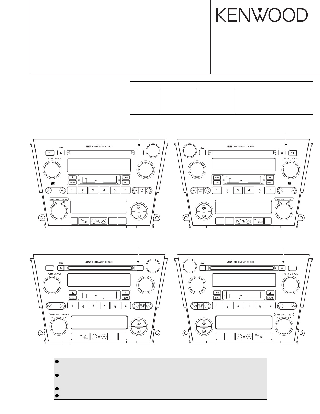
Model Model Name Parts No. Destination
GX-201LE GX-201LEF2 86201AG410 Europe (left-hand-drive cars)
GX-201RE GX-201REF2 86201AG310 Europe (right-hand-drive cars)
GX-201KE GX-201KEF2 86201AG210 Other Areas (right-hand-drive cars)
GX-201SE GX-201SEF2 86201AG510 Other Areas (left-hand-drive cars)
Panel assy
( - )*
LOAD
CD
CHR BAND
TAPE
LOCAL
DX
SCAN
RDM
)
GX-201REF2
COMPACT
DIGITALAUDIO
LOAD
CD
CHR BAND
TAPE
LOCAL
DX
SCAN
RDM
© 2003-8 CREATED IN JAPAN
B53-0087-00 (N) 0
Panel assy
( - )*
ANTI-THEFT SYSETM
DOLBY B NR
B NR
VOL ADJ
REG
TUNE
TRACK
GX-201SEF2
COMPACT
DIGITALAUDIO
SCAN
TUNE
TRACK
* Part number of panel assy is undecided.
The knobs with numbers larger than 700 on exploded view are not supplied for service parts because
it is difficult to apply grease. Please change to panel assy (PA1) when you need repair to the knob.
The 6CD mechanism has not supplied repair parts for each part (for Optical Laser pickup, motor etc).
If you need repair to the 6CD mechanism please change to mechanism assy (D40-1170-15).
DC cord for service : E30-3801-15
Antenna connector replacement cord for service : E30-6255-05
B NR
DOLBY B NR
A/COFF
A/COFF
MODE
Panel assy
( - )*
MODE
LOAD
CHR BAND
CD
TAPE
GX-201KEF2
COMPACT
DIGITALAUDIO
LOAD
CD
CHR BAND
TAPE
MODE
A/C OFF
B NR
MODE
A/C OFF
DOLBY B NR
Panel assy
( - )*
TUNE
TRACK
SCAN
GX-201KEF2/LEF2/REF2/SEF2
CAUTION ON TRANSPORTING
When transporting the unit, 6CD-CH mechanism must be
put into the transport mode.
■ How to Achieve the Transport Mode
In order to achieve the transport mode, there should be no
disk and the mechanism nor should the mechanism be in the
waiting mode for disk loading.*
After displaying [NO DISC], turned off the ACC power source.
Keep the BU power source on.
* Non-waiting mode for disk loading
•Non-waiting mode for disk loading means the state where
the mechanism is displaying [NO DISC] and where the
mechanism shutter is closed.
•In other words, [NO DISC] is displayed 15 seconds after
the disk is taken out or when the shutter of the mechanism
is closed and [LOAD] key is pressed. (Pressing the [LOAD]
key causes the mechanism to enter the waiting and nonwaiting mode alternatively.)
• Pressing other source keys after taking all the disks out,
the mechanism shutter closes and it goes into non waiting
mode for disk loading. (At this point the display will indicate
the source selected and does not display [NO DISC].)
2. Center Scre w condition (By the e xternal view of the mechanism, it is possible to make judgment on this by the PLATERACK pin position.)
PLATE-RACK PIN
Fig. 3 Transport mode
■ Transport Mode Condition
1. Rear Arm condition (This can be confirmed in the condition
where the mechanism cover is in place.)
REAR ARM
Fig. 1 Transport mode
PLATE-RACK PIN
Fig. 4 Up/Down center screw connection condition
■
The Reason to Put the Mechanism in the T ransport Mode
1. Protection of Rear Arm
Putting the mechanism into the transport mode is a protection against the Rear Arm to get deformed from the vibration during transport or sudden fall. Deformity in the Rear
Arm may result in loss of strength for holding the disk in
place.
2. Protection against error at the time of initial search
Putting the mechanism into the transport mode is also a
protection against an error or mechanism lock when the
power is put on again. When the back up is turned off , platerack pin could move from the vibration during transport or
sudden fall.
This would cause the system to go into an error detection
of the center screw is not in connection although, in fact, it
is in connected condition.
Fig. 2 Waiting mode for disk loading
2
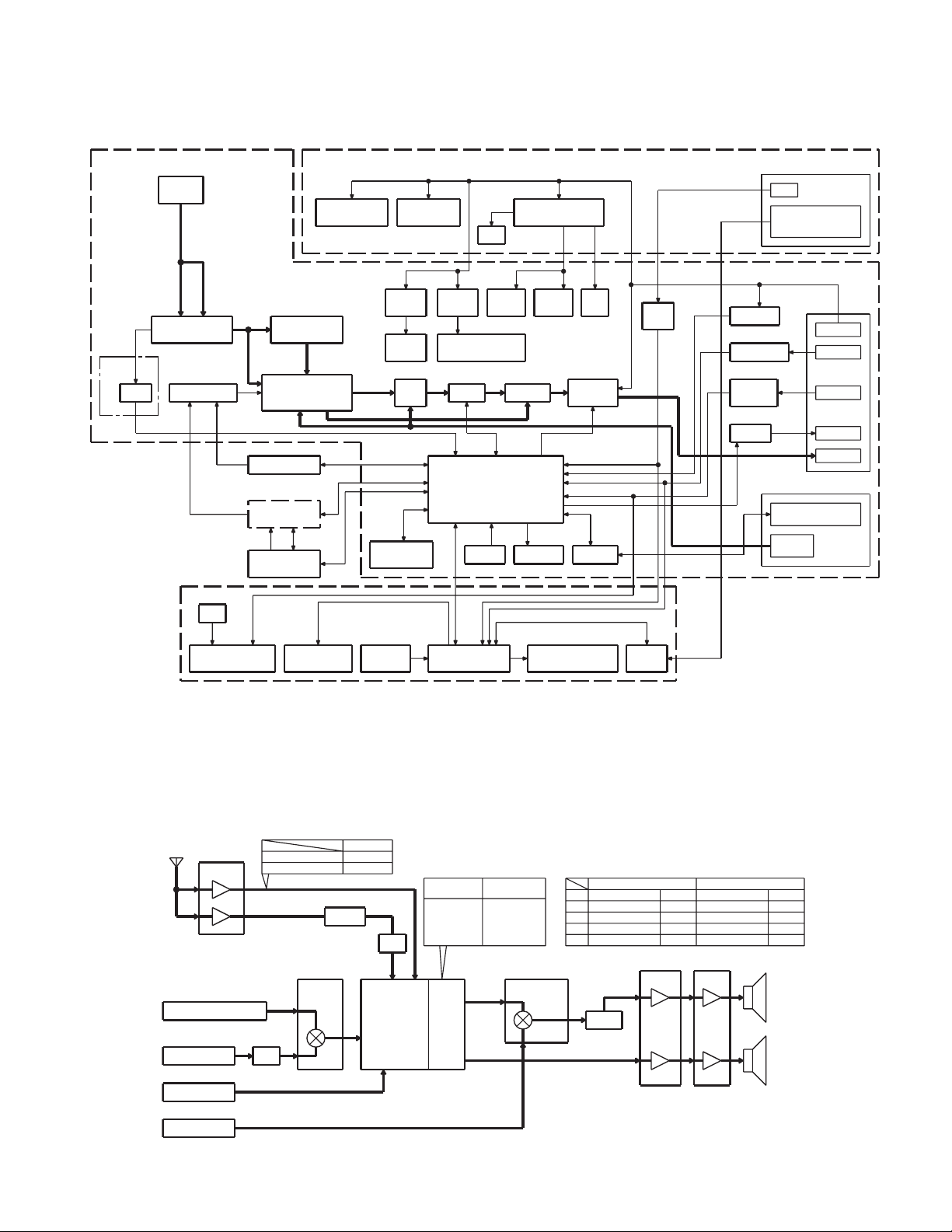
BLOCK DIAGRAM
(X14- ) (X89-254)
W1
FM/AM
ANT
AM
FM
A3 IC12
(2-71,
2-72)
ONLY
IC13,
FA/AM TUNER
(FRONT END)
IC2114
RDS MUTE
SELECTOR
IC22
E-VOL/
SIGNAL
PROCESSOR IC
6CD MECHA
(X87-3052-70)
DOLBY (IC1)
CASSETTE
(X25-929)
MECHA
6CD SERVO
AVR AVR
AM NOISE
CANCELLER
DC/DC
AVR
A1 A2
DC/DC
AUDIO HEAT CONTROL
IC23
FRONT
NAVI
SW
REAR
X81
OSC
12.582MHz
GX-201KEF2/LEF2/REF2/SEF2
IC11IC21IC31
CASSETTE BU5V, AUDIO8V,
DC/DC
AVR
DC/DC
IC81
SYSTEM u-COM
IC82
RESET BUS I/F
LED10V AVR
X25
AVR AVR
IC31-34Q401,402
FIX-EQ
BUZZER
FM 8VAM 8V
BZ81
IC41
POWER
AMP
SW
5V
Q813Q102Q104Q605Q602
IC83
IGN
DET
Q808
J1
IGN
AIR-CONDITIONER
UART
COMMUNICATION
Q815
BU DET
Q807
ACC DET
Q802,823,824
ILLM +/DET
Q816
P-ANT
J1
BUS
(COMMUNICATION)
BUS
(AUDIO)
J2
BU
ACC
ILLM +/-
P-ANT
SP
X89
LED
ILLUMINATION FL DISPLAY
ANT
TUNER
FM
AM : 215mV-rms
AM
GX-201KEF2
GX-201REF2/LEF2
CASSETTE-MECHA
CS : DOLBY LEVEL300mV-rms
IC24
6CD-MECHA
CD : 1.2V-rms
ISO
-1dB
EXT-UNIT
CH : 1.2V-rms
NAVI
NAVI : 1.2V-rms
AUDIO KEY
MATRIX I/F
FM
500mV-rms
270mV-rms
IC12
AM/NC
0dB
-7.5dB
SELECTOR
0dB
0dB
PANEL
u-COM
FL DISPLAY
LEVEL DIAGRAM
LEVEL DIFFERENCE OF EACH SAUCE
-1.5dB
-23.8dB
(CH 1W OUTPUT)
AM
FM
CS
6CD
CH
Q401,
402
LPF
MPX,
LOUD,
E-VOL,
BASS,
TRE,
MID
GX-201KEF2
CD : +6dB
CS : +8dB
: +5dBCH
FM : +7dB
: +16dBAM
FAD,
BAL
GX-201REF2
GX-201LEF2
CD
CS
CH
FM
AM
FRONT
REAR
: +6dB
: +8dB
: +5dB
: +10.5dB
: +18dB
IC23IC22IC21
SELECTOR
Q24,
25ED2 or ED3IC1ED1
UARTHEAT CONTROL
GX-201KEF2 GX-201REF2/LEF2
1kHz 30% mod.
1kHz 75kHz dev.
315kHz 0dB
1kHz 0dB
1kHz 0dB
IC31-34
MUTE
-0.5dB
FIX-EQ
+7.7dB
-2.5dB
-18dB
-6dB
-16.5dB
-1dB
0dB
1kHz 30% mod.
1kHz 40kHz dev.
315kHz 0dB
1kHz 0dB
1kHz 0dB
IC41
AMP
+26dB
+26dB
-16dB
-8dB
-16.5dB
-1dB
0dB
FRONT
SP
REAR
SP
3

GX-201KEF2/LEF2/REF2/SEF2
COMPONENTS DESCRIPTION
● SYNTHESIZER UNIT (X14-694x-xx)
Ref. No. Application / Function Operation / Condition / Compatibility
IC1 Cassette mechanism sub-motor IC Cassette sub-motor power supply
IC11 FM diversity IC FM diversity switching (Only for GX-201KEF2)
IC12 AM noise canceller IC AM noise canceller
IC13 2-piece ope-amp RDS noise amp (Only for GX-201LEF2/REF2)
IC14 RDS demodulation IC RDS demodulation (Only for GX-201LEF2/REF2)
IC21 Ope-amp with switch CD/Cassette switching
IC22 Electronic volume BASS/MID/TRE, MPX, Mute, Electronic volume
IC23 Ope-amp with switch Audio/NAVI switching
IC24 2-piece ope-amp CD isolation amp, LPF
IC31~34 4-piece ope-amp FIX-EQ
IC35 2-piece ope-amp 1/2 VCC output
IC41 Power amp 4ch power amp
IC81 System µ-com System control
IC82 Reset IC System reset detection
IC83 I2C BUS IC F-BUS communication
IC84 2-piece NOR circuit For hard muting
IC85 EEPROM Bug counter-measure
IC86,87 Inverter circuit F-BUS control
Q1,2
Q101 Diversity switch When turned ON, turns diversity OFF (Only for GX-201KEF2)
Q102,103 FM power supply switch When FM, 8V output
Q104,105 AM power supply switch When AM, 8V output
Q106 IF count detection When detecting IF count, Lo output
Q107 RDS data buffer RDS data buffer output (Only for GX-201LEF2/REF2)
Q108 S-meter buffer S-meter voltage output
Q151,152 Noise amp Noise detection constant switching (Only for GX-201LEF2/REF2)
Q153 Noise amp Noise detection output buffer (Only for GX-201LEF2/REF2)
Q202 Mute switch For muting within electronic volume
Q401,402 NAVI mute For NAVI muting at interruption
Q403 SVR switch For SVR discharging
Q404 SVR switch For SVR discharging at over voltage
Q601,602 Audio DC/DC power supply switch For DC/DC audio
Q604,605 Heater DC/DC power supply switch For DC/DC heater
Q606,607 DC/DC control switch For switching internal frequency
Q650 Audio DC/DC power supply switch For DC/DC audio
Q651 Heater DC/DC power supply switch For DC/DC heater
Q801 Buzzer switch For buzzer
Cassette mechanism main motor power supply switch
For cassette mechanism main motor
4
GX-201KEF2/LEF2/REF2/SEF2
COMPONENTS DESCRIPTION
Ref. No. Application / Function Operation / Condition / Compatibility
Q802 Illumination + detection For illumination + detection
Q803 Reset output switch for F-BUS When resetting F-BUS, Hi output
Q804 NAVI mute switch When muting NAVI, Hi output
Q805 IF count detection When detecting IF count, Lo output
Q806 P-ANT circuit control switch When tuner, GND electric potential output
Q807 ACC detection When ACC ON detection, Lo output
Q808 IGN detection When IGN ON detection, Lo output
Q809 SYS_ON current buffer When SYS_ON Hi, Lo output
Q810 Hard reset switch When HARD_RESET ON, Lo output
Q812 BUS_OFF switch When F-BUS system OFF, Hi output
Q813 P-ON5V power supply switch For P-ON5V
Q815 BU detection When BU ON, Lo output
Q816 P-ANT circuit control switch When tuner, BU electric potential output
Q817,818 P-ANT circuit protection P-ANT short circuit protection
Q820 F-BUS mute output When mute ON, Hi output
Q821 BUS_ON detection When F-BUS system ON, Hi input
Q822 BUS_ON switch When F-BUS system ON, Hi output
Q850,852 Illumination - detection switch When detecting illumination -, Hi output
Q853 Illumination - detection switch When detecting illumination -, Lo output
● SWITCH UNIT (X25-929x-xx)
Ref. No. Application / Function Operation / Condition / Compatibility
IC1 Display control µ-com VFD control, Key intake
IC3 EEPROM For bug counter-measures
Q1 Audio VFD5V switch When audio VFD ON, 5V output
Q2 Audio VFD5V switch When audio DC/DC ON, Lo output
Q4 Heater VFD5V switch When heater VFD ON, 5V output
Q5 Heater VFD5V switch When heater DC/DC ON, Lo output
Q11 F differential indicator power supply switch When F-differential indicator ON, 5V output
Q12 R differential indicator power supply switch When R-differential indicator ON, 5V output
Q21 Multiple-push reset circuit detection When detecting REP/RDM, DWN_SEEK, Hi output
Q22 Multiple-push reset circuit detection When resetting by multiple push, Lo output
Q23 Multiple-push reset circuit detection When TONE (BAL/FAD) detected, Lo output
Q24 Heater UART communication control Heater UART communication control (TX)
Q25 Heater UART communication control Heater UART communication control (RX)
Q26 SW5V power supply switch When IGN ON, 5V output
Q27 Panel illumination switch When panel illumination ON, 10V output
5
 Loading...