

Page 1

GRAPHIC EQUALIZER
G-EQ300
INSTRUCTION MANUAL
KENWOOD CORPORATION
B60-3538-08 KO (K,P,Y,C,M,X,T)
97/12 11 10 9 8 7 6 5 4 3 2 1 96/12 11 10 9 8 7 5
MC
Page 2
Introduction
G-EQ300 (En/K)
Before applying power
Caution : Read this section carefully to ensure safe operation.
2
Units are designed for operation as follows.
U.S.A. and Canada ................................................................................................................................................................ AC 120 V only
Australia ................................................................................................................................................................................. AC 240 V only
China........................................................................................................................................................................................ AC 220 V only
U.K. and Europe ..................................................................................................................................................................... AC 230 V only
*Other countries...............................................................................................................................AC 110-120 / 220-240 V switchable
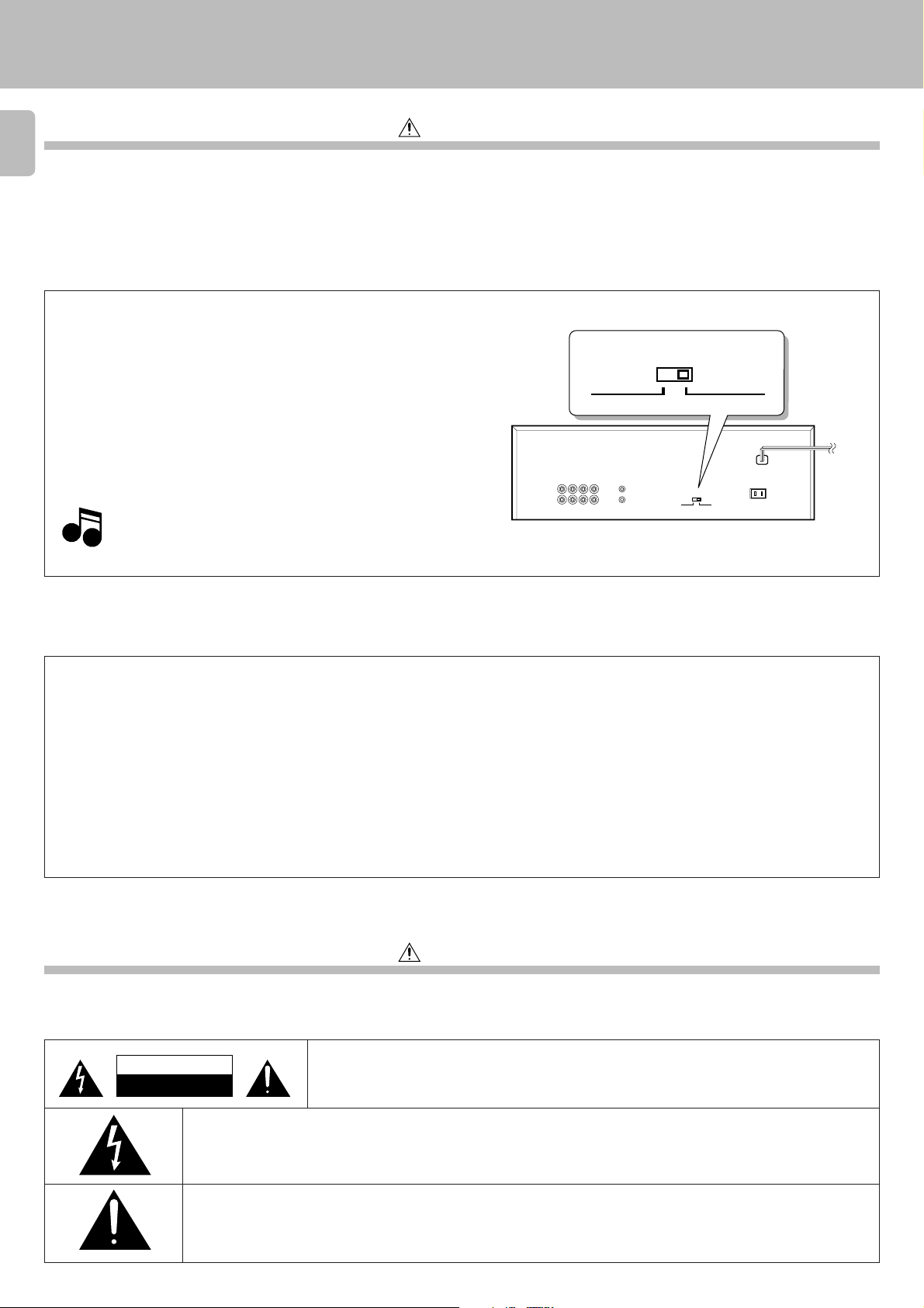
*AC voltage selection
The AC voltage selector switch on the rear panel is set to the voltage
that prevails in the area to which the unit is shipped. Before connecting
the power cord to your AC outlet, make sure that the setting position
of this switch matches your line voltage. If not, it must be set to your
voltage in accordance with the following direction.
Note:
Our warranty does not cover damage caused by excessive
Note
Note
line voltage due to improper setting of the AC voltage
selector switch.
AC voltage selector switch
VOLTAGE SELECTOR
AC 110 - 120V
Move switch lever to match your line voltage with a small screwdriver
or other pointed tool.
AC 220 - 240V
‘
VOLTAGE SELECTOR
AC 220 - 240V
AC 110 - 120V
‘
‘
‘
For the United Kingdom
Factory fitted moulded mains plug
1. The mains plug contains a fuse. For replacement, use only a 13- Amp ASTA-approved (BS1362) fuse.
2. The fuse cover must be refitted when replacing the fuse in the moulded plug.
3. Do not cut off the mains plug from this equipment. If the plug fitted is not suitable for the power points in your home or the cable is too short to reach
a power point, then obtain an appro priate safety approved extension lead or adapter, or consult your dealer.If nonetheless the mains plug is cut off,
remove the fuse and dispose of the plug immediately, to avoid a possible shock hazard by inadvertent connection to the mains supply.
IMPORTANT :
The wires in the mains lead are coloured in accordance with the following code :
Blue: Neutral
Brown : Live
Do not connect those leads to the earth terminal of a three - pin plug.
Safety precautions
Caution : Read this section carefully to ensure safe operation.
WARNING : TO PREVENT FIRE OR ELECTRIC SHOCK, DO NOT EXPOSE THIS
APPLIANCE TO RAIN OR MOISTURE.
CAUTION
RISK OF ELECTRIC SHOCK
DO NOT OPEN
CAUTION: TO REDUCE THE RISK OF ELECTRIC SHOCK, DO NOT REMOVE COVER (OR BACK). NO
USER-SERVICEABLE PARTS INSIDE, REFER SERVICING TO QUALIFIED SERVICE PERSONNEL.
THE LIGHTNING FLASH WITH ARROWHEAD SYMBOL, WITHIN AN EQUILATERAL TRIANGLE, IS INTENDED TO ALERT THE
USER TO THE PRESENCE OF UNINSULATED “DANGEROUS VOLTAGE” WITHIN THE PRODUCT’S ENCLOSURE THAT MAY
BE OF SUFFICIENT MAGNITUDE TO CONSTITUTE A RISK OF ELECTRIC SHOCK TO PERSONS.
THE EXCLAMATION POINT WITHIN AN EQUILATERAL TRIANGLE IS INTENDED TO ALERT THE USER TO THE PRESENCE
OF IMPORTANT OPERATING AND MAINTENANCE (SERVICING) INSTRUCTIONS IN THE LITERATURE ACCOMPANYING
THE APPLIANCE.
Page 3

Introduction
G-EQ300 (En/K)
Special features
Large FL display, 14-band equalizer
and 27-spectrum analyzer
MANUAL/REFERENCE modes
PARAMETRIC/GRAPHIC modes
GENRE mode
3
The large FL display, 14-band equalizer and 27-spectrum analyzer features
high visibility of information and make it possible to set EQ (equalizer) curves
with high accuracy.
MANUAL: Five preset patterns have been factory-preset for this mode, too. In
this mode, it is also possible to preset (assign) equalizer patterns
created by the user in place of the factory presets. @
REFERENCE: Five exemplary patterns have been preset at the factory. #
PARAMETRIC: Equalizer curves can be created by setting up to 3 center
frequencies and the equalizing levels for them. %
GRAPHIC: The equalizer curve can be adjusted in a detailed way for every
frequency range. It is also possible to fine-adjust a curve which
has been created in the PARAMETRIC mode. The GRAPHIC
mode is to be used when detailed adjustment of acoustic
compensation is required. &
A total of 30 playback patterns have been factory-preset by combining five
recommended equalizer patterns with six music genres, so that any of them
can be selected by actually comparing them. Similarly, selection from 30
types of recording patterns for playback on car stereo or from 30 types of
recording patterns for playback on headphone stereo is also available. Select
the optimum equalizer pattern according to the music genre and purpose of
use of the pattern. (
Contents
Introduction .................................................................................. 2
3
Before applying power.............................................................. 2
3
Safety precautions .................................................................... 2
Special features ........................................................................ 3
3
Contents .................................................................................... 3
Accessories ............................................................................... 3
3
IMPORTANT SAFEGUARDS ....................................................... 4
Before operation .......................................................................... 6
Safety precautions .................................................................... 6
Maintenance ............................................................................. 6
Names and functions of parts ................................................... 7
System connections .................................................................... 8
About the system control connections ..................................... 9
Display ......................................................................................... 10
Switching the display modes.................................................. 10
Caution : Read the pages marked carefully to ensure safe operation.
Accessories
Check that the following accessories are present.
Demonstration method ........................................................... 11
Operation of graphic equalizer ............................................... 12
Operation of MANUAL feature ............................................... 12
Operation of REFERENCE feature ........................................... 13
Equalizer pattern list ............................................................... 14
Creation of desired equalizer patterns .................................. 15
Operation in PARAMETRIC mode ........................................... 15
Operation in GRAPHIC mode .................................................. 17
Registration of EQUALIZER pattern ........................................ 18
Operation of GENRE feature ................................................... 19
REVERSE key ........................................................................... 20
Use of equalizer effect with tape ........................................... 21
Applying equalizer effect to tape playback ............................ 21
Tape recording of sound with equalizer effect ....................... 22
Functions of the graphic equalizer......................................... 23
In case of difficulty.................................................................... 24
3
Specifications ............................................................................ 25
Audio cord (2)
System control cord (1)
* AC plug adaptor (1)
*Use to adapt the plug on the
power cord to the shape of
the wall outlet. (Accessory
only for regions where use is
necessary.)
Page 4
IMPORTANT SAFEGUARDS
3
Caution : Read this page carefully to ensure safe operation.
Please read all of the safety and operating instructions before
4
operating this appliance. Adhere to all warnings on the appliance
and in the instruction manual. Follow all the safety and operating
instructions. These safety and operating instructions should be
retained for future reference.
1. Power sources – The appliance should be connected to a
power supply only of the type described in the instruction
manual or as marked on the appliance. If you are not sure of
the type of power supply to your home, consult your appliance
dealer or local power company. For appliances intended to
operate from battery power, or other sources, refer to the
instruction manual.
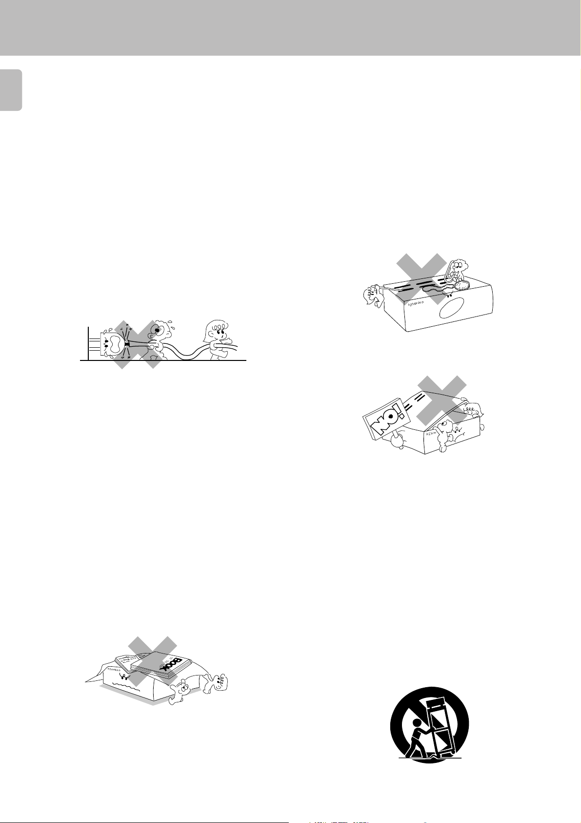
2. Power-cord protection – Power-supply cords should
be routed so that they are not likely to be walked on or
pinched by items placed upon or against them, pay
particular attention to cords at plugs, convenience
receptacles, and the point where they exit from the
appliance.
Never pull or stretch
the cord.
G-EQ300 (En/K)
6. Temperature – The appliance may not function properly
if used at extremely low, or freezing temperatures. The
ideal ambient temperature is above +5°C (41°F).
7. Heat – The appliance should be situated away from heat
sources such as radiators, heat registers, stoves, or
other appliances (including amplifiers) that produce heat.
8. Electric shock – Care should be taken so that objects do
not fall and liquid is not spilled into the enclosure
through openings. If a metal objects, such as a hair pin
or a needle, comes into contact with the inside of this
appliance, a dangerous electric shock may result. For
families with children, never permit children to put
anything, especially metal, inside this appliance.
3.
CAUTION – Polarization – This appliance may be
equipped with a polarized alternating-current line plug (a plug
having one blade wider than the other). This plug will fit into the
power outlet only one way. This is a safety feature. If you are
unable to insert the plug fully into the outlet, try reversing the
plug. If the plug should still fail to fit, contact your electrician to
replace your obsolete outlet. Do not defeat the safety purpose
of the polarized plug.
4. Ventilation – Slots and openings in the cabinet are provided
for ventilation and to ensure reliable operation of the appliance
and to protect it from overheating, and these openings must
not be blocked or covered. The appliance should be situated so
that its location or position does not interfere with its proper
ventilation.
To maintain good ventilation, do not put records or a table-cloth
on the appliance. Place the appliance at least 10 cm away from
the walls.
Do not use the appliance on a bed, sofa, rug or similar surface
that may block the ventilation openings. This appliance should
not be placed in a built-in installation such as a bookcase or rack
unless proper ventilation is provided or the manufacturer’s
instructions have been adhered to.
9. Enclosure removal – Never remove the enclosure. If
the internal parts are touched accidentally, a serious
electric shock might occur.
10.Magnetic fields – Keep the appliance away from sources
of magnetic fields such as TV sets, speaker systems,
radios, motorized toys or magnetized objects.
11.Cleaning – Unplug this appliance from the wall outlet
before cleaning. Do not use volatile solvents such as
alcohol, paint thinner, gasoline, or benzine, etc. to clean
the cabinet. Use a clean dry cloth.
12.Accessories – Do not place this appliance on an unstable cart,
stand, tripod, bracket, or table. The appliance may fall, causing
serious injury to a child or adult, and serious damage to the
appliance. Use only with a cart, stand, tripod, bracket, or table
recommended by the manufacturer, or sold with the appliance.
Any mounting of the appliance should follow the manufacturer’s
instructions, and should use a mounting accessory
recommended by the manufacturer. An appliance and cart
combination should be moved with care. Quick stops, excessive
force, and uneven surfaces may cause the appliance and cart
combination to overturn.
5. Water and moisture – The appliance should not be
used near water - for example, near a bathtub, washbowl,
kitchen sink, laundry tub, in a wet basement, or near a
swimming pool, etc.
Page 5
3
Caution : Read this page carefully to ensure safe operation.
13.Lightning – For added protection for this appliance during a
lightning storm, or when it is left unattended and unused for
long periods of time, unplug it from the wall outlet and
disconnect the antenna or cable system. This will prevent
damage to the appliance due to lightning and power-line
surges.
IMPORTANT SAFEGUARDS
G-EQ300 (En/K)
18.Power lines – An outside antenna system should not be
located in the vicinity of overhead power lines or other electric
light or power circuits, or where it can fall into such power lines
or circuits. When installing an outside antenna system, extreme
care should be taken to keep from touching such power lines
or circuits as contact with them might be fatal.
5
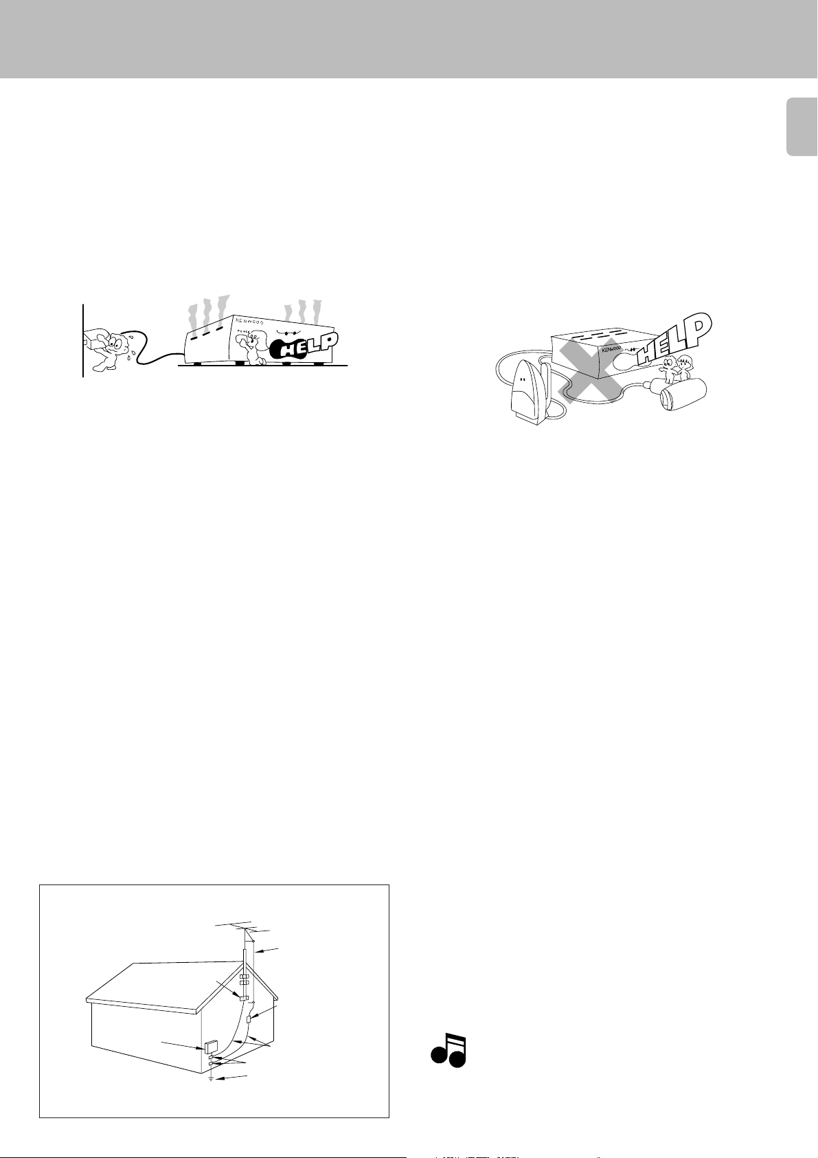
14.Abnormal smell – If an abnormal smell or smoke is
detected, immediately turn the power OFF and unplug
the appliance from the wall outlet. Contact your dealer or
nearest service center.
POWER OFF!
15.Damage requiring service – The appliance should be
serviced by qualified service personnel when:
A. The power-supply cord or the plug has been damaged.
B. Objects have fallen, or liquid has been spilled into the
appliance.
C. The appliance has been exposed to rain or water.
D. The appliance does not appear to operate normally by
following the instruction manual. Adjust only those controls
that are covered by the instruction manual as an improper
adjustment of other controls may result in damage and will
often require extensive work by a qualified technician to
restore the appliance to its normal operation.
E. The appliance has been dropped, or the enclosure
damaged.
F. The appliance exhibits a marked change in performance.
16.Servicing – The user should not attempt to service the
appliance beyond that described in the instruction
manual. All other servicing should be referred to qualified
service personnel.
19.AC outlets – Do not connect other audio equipment
with a power consumption larger than that specified to
the AC outlet on the rear panel. Never connect other
electrical appliances, such as an iron or toaster, to it to
prevent fire or electric shock.
20. Overloading – Do not overload wall outlets, extension cords,
or integral convenience receptacles as this can result in a risk
of fire or electric shock.
21. Attachment – Do not use attachments not recommended by
the appliance manufacturer as they may cause hazards.
22. Replacement parts – When replacement parts are required,
be sure the service technician has used replacement parts
specified by the manufacturer or have the same characteristics
as the original parts. Unauthorized substitutions may result in
fire, electric shock, or other hazards.
23. Safety check – Upon completion of any service or repairs to
this appliance, ask the service technician to perform safety
checks to determine that the appliance is in proper operating
condition.
17.Outdoor antenna grounding – If an outside antenna is
connected to the appliance, be sure the antenna system
is grounded so as to provide some protection against
voltage surges and built up static charges. Article 810 of
the National Electrical Code ANSI/NFPA 70, provides
information with respect to proper grounding of the
mast and supporting structure, grounding of the lead-in
wire to an antenna discharge unit, size of grounding
conductors, location of antenna discharge unit,
connection to grounding electrodes, and requirements
for the grounding electrode. See Figure.
EXAMPLE OF ANTENNA GROUNDING AS PER
NATIONAL ELECTRICAL CODE
ANTENNA
LEAD IN WIRE
GROUND
CLAMPS
ANTENNA
DISCHARGE UNIT
ELECTRIC
SERVICE
EQUIPMENT
NEC – NATIONAL ELECTRICAL CODE
(NEC SECTION 810-20)
GROUNDING CONDUCTORS
(NEC SECTION 810-21)
GROUND CLAMP
POWER SERVICE GROUNDING
ELECTRODE SYSTEM
(NEC ART 250, PART H)
Notes
Notes
1. Item 3 is not required except for grounded or polarized equipment.
2. Item 17 and 18 are not required except for units provided with antenna
terminals.
3. Item 17 complies with UL in the U.S.A.
Page 6
Before operation
G-EQ300 (En/K)
Unpacking
6
Unpack the unit carefully and make sure that all accessories are put aside so they will not be lost.
Examine the unit for any possibility of shipping damage. If your unit is damaged or fails to operate, notify your dealer immediately. If your unit was shipped
to you directly, notify the shipping company without delay. Only the consignee (the person or company receiving the unit) can file a claim against the
carrier for shipping damage.
We recommend that you retain the original carton and packing materials for use should you transport or ship the unit in the future.
Keep this manual handy for future reference.
Safety precautions
Beware of condensation
When water vapor comes into contact with the surface of cold material,
water drops are produced.
If condensation occurs, correct operation may not be possible, or the
unit may not function correctly.
This is not a malfunction, however, the unit should be dried.
(To do this, turn the ON/STANDBY switch ON and leave the unit as it
is for several hours.)
Be especially careful in the following conditions:
¶When the unit is brought from a cold place to a warm place, and there
is a large temperature difference.
¶When a heater starts operating.
¶When the unit is brought from an air-conditioned place to a place of
high temperature with high humidity.
¶When there is a large difference between the internal temperature of
the unit and the ambient temperature, or in conditions where condensation occurs easily.
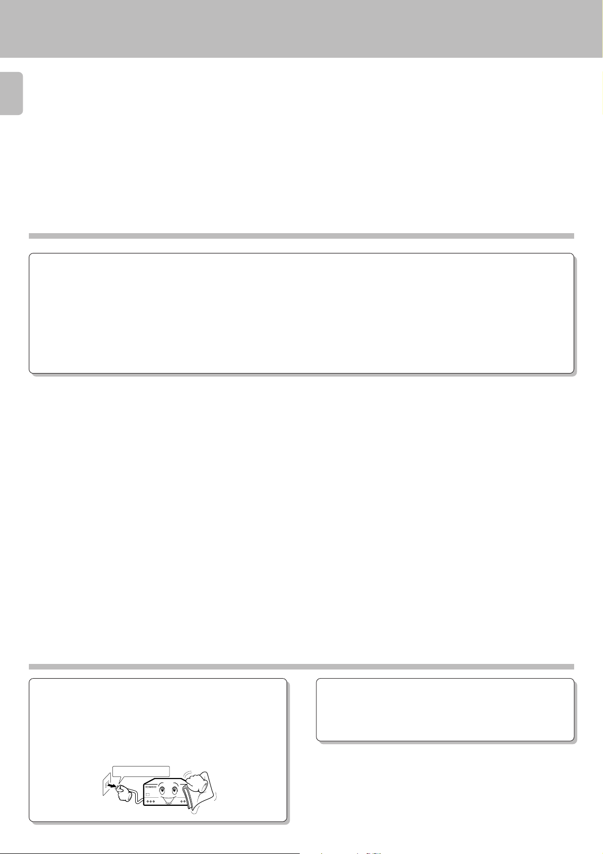
Maintenance
Cleaning
Unplug this appliance from the wall outlet before cleaning. Do not use
volatile solvents such as alcohol, paint thinner, gasoline, or benzine,
etc. to clean the cabinet. Use a clean dry cloth.
Unplug power cord
Caution against contact revitalizer
Do not use contact cleaners because it could cause a malfunction. Be
specially careful against contact cleaners containing oil, for they may
deform the plastic componente.
Page 7
Names and functions of parts
G-EQ300 (En/K)
1
32
ON/STANDBY
MAIN POWER
-ON –OFF
EQ.EFFECT
Graphic equalizer display
Spectrum analyzer display
Character display
4 56
TAPE
PATTERN
PAUSE
REVERSE
DISPLAY
TAPE
Character display
Frequency display
indicator
******
EQ. ON
MEMORY
MANUAL
2.5k 3.9k 6.3k 10k 16 k400 625 1k 1.5k25040 63 98 160
REFERENCE
GRAPHIC
PARAMETRIC
F1 F2 F3
NARROWWIDE
Indicators
EQ. ON GRAPHIC
MEMORY PARAMETRIC
MANUAL F1, F2, F3
REFERENCE WIDE/NARROW
7
Display
8
7
GRAPHIC/
PARAMETRIC
WIDE/NARROW
FREQUENCY JOG
FLAT
MANU./
REF.
1
4
2
5
3
MEMORY
BYPASS
POP./1
ROCK/2
CAR
H.P.ST.
FUSION/4
CLASSIC/5
JAZZ/3
MOVIE
F1
F2
F3
90
EQ.LEVEL
!@#$%^ &* ()
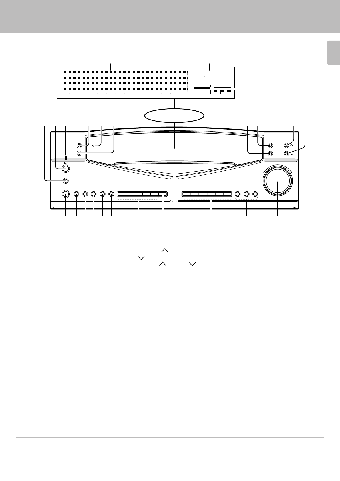
1 MAIN POWER key
Switch the unit ON mode.
2 ON/STANDBY key
Switch the unit between ON mode
and STANDBY mode.
3 Standby indicator
Lights up to indicate that a small
amount of current flows in the unit.
4 PATTERN key
Press to enter or quit the genre mode.
5 TAPE indicator
Lights up when the TAPE key is
pressed to ON.
6 PAUSE key
Press to let an equalizer curve pause
temporarily.
7 WIDE/NARROW key
Each press of the key switches the
curve slope alternately between WIDE
and NARROW.
8 GRAPHIC/PARAMETRIC key
GRAPHIC: Select this mode when
adjusting an equalizer curve.
PARAMETRIC: Select this mode
when creating an equalizer curve according to center frequencies.
90 EQ. LEVEL
/
(DOWN) keys
Press the
(UP)
(UP) or (DOWN)
key to increase or decrease the equalizer level.
! EQ. EFFECT key
Press to turn the equalizer mode ON
and OFF.
@ TAPE key
Use when playing back or recording a
tape.
# DISPLAY key
Press to switch the display mode or to
select the demonstration mode.
$ REVERSE key
Press to reverse an equalizer curve.
% FLAT key
Press to make an equalizer curve flat.
^ MANU./REF. key
Press to switch the manual and reference functions alternately.
& Preset keys (1 to 5)
Typical equalizer patterns have been
preset under these keys so that you
can select any one of them easily.
¡
* MEMORY key
Press this key when registering a usercreated equalizer pattern.
( Genre keys
Press in the genre mode to select the
desired music genres and their equalizer patterns.
) Frequency keys (F1, F2, F3)
Each key can store a desired center
frequency.
¡ FREQUENCY JOG knob
Rotate the control knob to adjust the
frequency band (range).
STANDBY indicator
While standby mode is indicated, a small amount of power is supplied to the system to back up the memory. In this mode, the
system can be turned ON by remote control.
Page 8
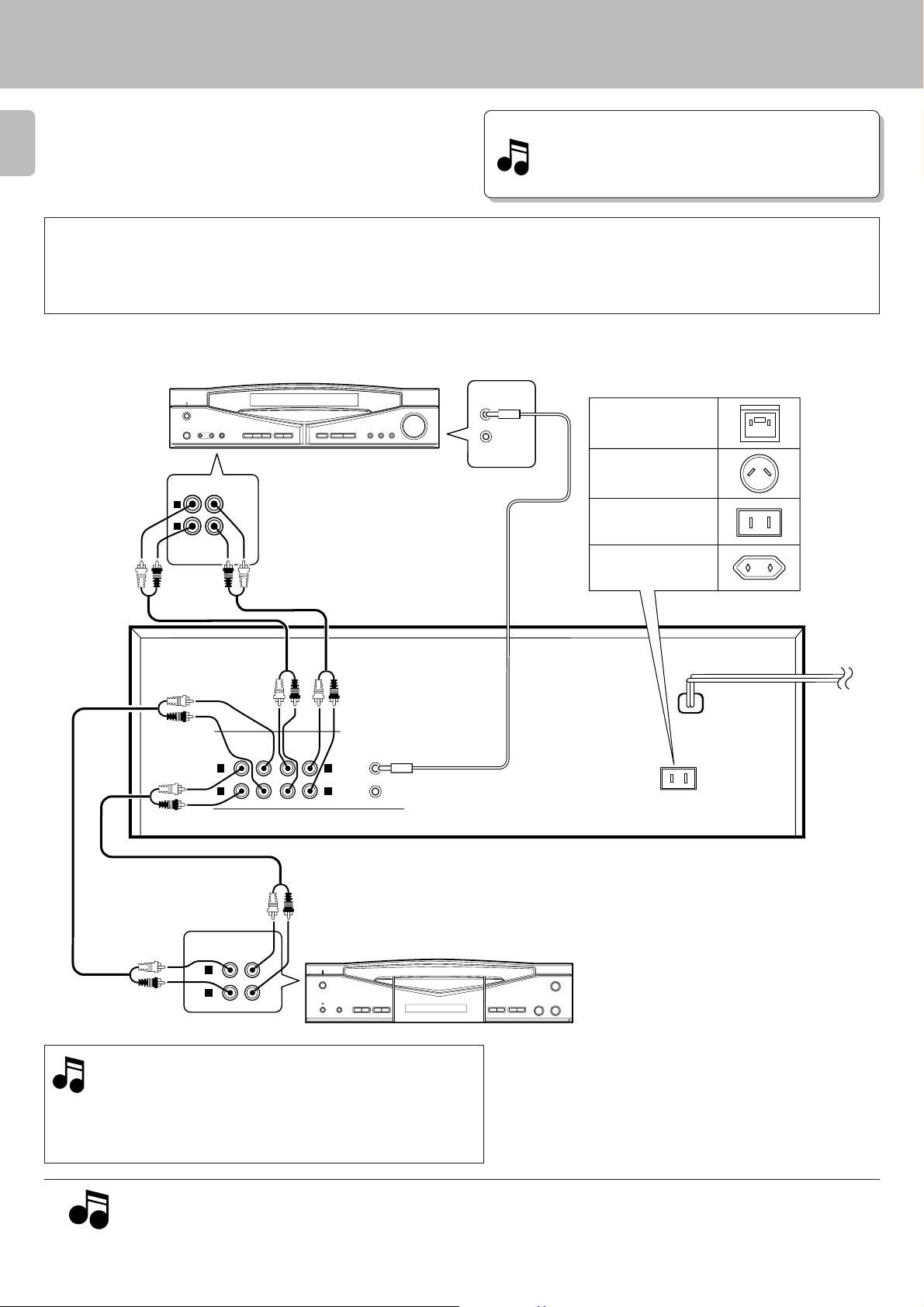
System connections
Make connection as shown below. When connecting the
related system components, refer also to the instruction
manuals of the related components.
8
3 Caution: Do not plug in the power lead until all connections are completed.
G-EQ300 (En/K)
Malfunction of microprocessor
If operation is not possible or erroneous display appears even
though all connections have been made properly, reset the
microprocessor referring to “In case of difficulty”.
¢
Caution regarding placement
( Except for U.S.A., Canada )
To maintain proper ventilation, be sure to leave a space around the unit (from the largest outer dimensions including projections) equal to, or greater than,
shown below.
Left and right panels: 10 cm, rear panel: 10 cm
*CAUTION (For U.K.)
When using the AC outlet epuipped
with this unit, be sure to consult your
AV CONTROL CENTER
TAPE 2
(MONITOR)
L
R
REC PLAY
Connect to the TAPE 2 (MONITOR)
jacks
Set the TAPE 2 (MONITOR ) switch
to the monitoring position.
SYSTEM
CONTROL
dealer for the correspond-ing plug.
U.K.
Australia
U.S.A., Canada,
China and US military
*
Other countries
Audio cords
OUT
OUT
LINE
IN
OUT
SYSTEM
CONTROL
L
R
Cassette tape deck (optional)
Audio cords
TAPE
PLAYINREC
L
R
LINE
REC
PLAY
IN
L
R
Use the numbers 9 0 ! @ on the rear panel of this unit
when connecting it to an AV CONTROL CENTER or
RECEIVER.
Connections are easily completed by using Audio cords
to make connections to the same numbers on the other
component.
To wall
AC outlet
AC OUTLET
System control cord
This unit
÷When a cassette deck is connected to the graphic equalizer,do not
connect the system control cord to the cassette deck.
÷When connecting the audio cords (cords with pin plugs on each
end), insert the white plugs into the L (Left) jacks and red plugs into
the R (Right) jacks.
1. Connect all cords firmly. If connections are loose there could be loss of sound or noise produced.
2. When plugging and unplugging connection cords, be sure to first remove the power cord from the AC outlet. Plugging/unplugging connection
Notes
Notes
cords without removal of the power cord can cause malfunctions or damage on the unit.
3. Do not connect up a power source which is larger than that indicated on the socket at the rear of the unit.
Page 9
System connections
G-EQ300 (En/K)
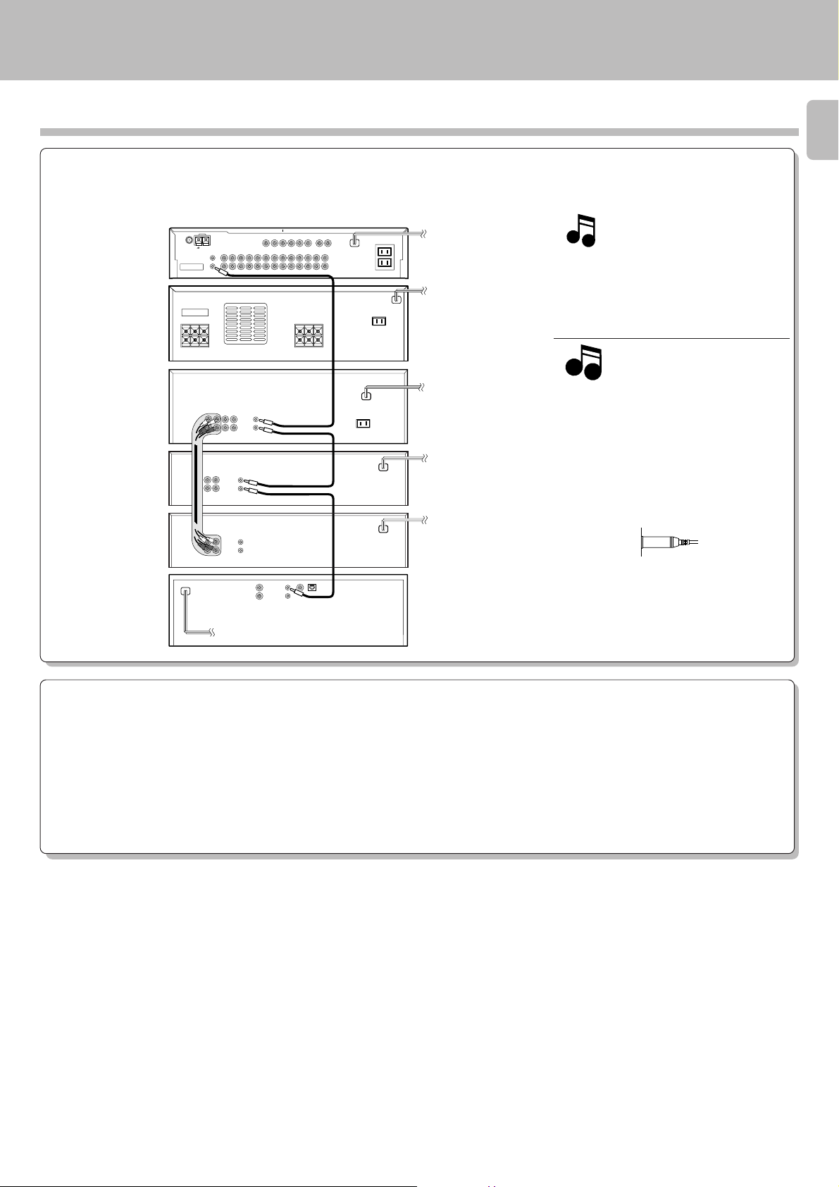
About the system control connections
When this unit is connected to KENWOOD audio component system “SERIES 21”, also connect them through the system control cords to
allow system-control operations between components.
Connection example
9
AV
CONTROL
CENTER
POWER
AMPLIFIER
GRAPHIC
EQUALIZER
CASSETTE
DECK 1
CASSETTE
DECK 2
CD
PLAYER
SYSTEM
CONTROL
The SERIES 21 components which can be
system-connected with this unit include the
LD player, MD recorder and DVD player.
System
control cord
Notes
Notes
SYSTEM
CONTROL
1. Do not connect the SERIES 21 components
to other system components using system
control cords.
2. Do not connect system control cords to any
components other than those specified by
SYSTEM
CONTROL
System
control cord
KENWOOD. It may cause a malfunction
and damage your equipment.
3. Be sure the system control plugs are inserted all the way in to the system control
4
SYSTEM
*
CONTROL
terminals.
4.When a cassette deck is connected to the
*
graphic equalizer,do not connect the sys-
SYSTEM
CONTROL
System
control cord
tem control cord to the cassette deck.
About the system control operations
(Available operations when SERIES 21 components are connected through system control cords)
Remote Control
Lets you operate source components with the system remote supplied with AV CONTROL CENTER.
Automatic Operation
When you start playback from a source component, the input selector on AV CONTROL CENTER switches to that component automatically.
(Except TAPE 2)
Synchronized Recording
Lets you synchronize recording with the start of playback when recording from CD or LD .
Page 10

Display
G-EQ300 (En/K)
Preparation
10
¶Ensure that the MAIN POWER key is set to
ON.
MAIN POWER
-ON –OFF
Switching the display modes
Press the ON/STANDBY key to turn the unit ON.
1
ON/STANDBY
: Keys and control used in the operations described on this page.
Select the desired display mode.
2
DISPLAY
Graphic equalizer display mode
Shows how each frequency range is compensated.
The graphic equalizer display also appears for about 5 seconds, even
while the unit is in the spectrum analyzer display mode, when one of
the following operation is performed.
1. Turning the unit ON.
2. An operation key associated with an equalizer operation is pressed.
Spectrum analyzer display mode
Displays the frequency distribution of the source being played to allow
under standing at a glance.
The peak value of the varying level of each frequency range is held and
displayed for about 0.5 second.
Each press switches the display modes as follows.
1 Graphic equalizer display mode
2 Spectrum analyzer display mode
3 DEMO(Demonstration) mode
2.5k 3.9k 6.3k 10k 16 k400 625 1k 1.5k25040 63 98 160
Peak hold level
2.5k 3.9k 6.3k 10k 16 k400 625 1k 1.5k25040 63 98 160
DEMO(Demonstration) mode
After “DEMO” is displayed, the demonstration of the graphic equalizer
curves starts.
Page 11

GRAPHIC PARAMETRIC REFERENCE
MANUAL
Demonstration of equalizer curves can be displayed to help
the user understand the features of the equalizer better.
Demonstration method
Play a music source.
1
Select the “DEMO” mode.
2
DISPLAY
Display
G-EQ300 (En/K)
11
: Keys and control used in the operations described on this page.
Each press switches the display modes as follows.
1 Graphic equalizer display mode
2 Spectrum analyzer display mode
3 DEMO(Demonstration) mode
Demonstration is performed repeatedly in the following order.
To stop demonstration
DISPLAY
Page 12

Operation of graphic equalizer
EQ. ON
M
Five preset patterns have been factory-preset for this mode,
too. In this mode, it is also possible to preset (assign)
equalizer patterns created by the user in place of the factory
12
presets.
Operation of MANUAL feature
Play a music source.
1
Select the “EQ.ON” mode.
2
EQ.EFFECT
G-EQ300 (En/K)
: Keys and control used in the operations described on this page.
“EQ.ON” Lights up.
Set to “MANUAL“.
3
MANU./REF.
Select an equalizer pattern.
4
1
2
3
To cancel the equalizer effect:
EQ.EFFECT
Each press switches the display as follows.
1 MANUAL
2 REFERENCE
Select by pressing one of preset keys 1 to 5.
4
5
“EQ.ON” indicator goes off.
¶The pattern being displayed remains the same.
“MANUAL” Lights up.
MANUAL
“FLAT” key
Pressing the FLAT key makes the displayed curve flat. This
occurs in any mode.
FLAT
2.5k 3.9k 6.3k 10k 16 k400 625 1k 1.5k25040 63 98 160
2.5k 3.9k 6.3k 10k 16 k400 625 1k 1.5k25040 63 98 160
Page 13

EQ. ON
Five exemplary patterns have been preset at the factory.
M
Operation of REFERENCE feature
Play a music source.
1
Select the “EQ.ON” mode.
2
EQ.EFFECT
Operation of graphic equalizer
G-EQ300 (En/K)
13
: Keys and control used in the operations described on this page.
“EQ.ON” Lights up.
Set to “REFERENCE”.
3
MANU./REF.
Select an equalizer pattern.
4
1
2
3
To cancel the equalizer effect:
EQ.EFFECT
Each press switches the display as follows.
1 MANUAL
2 REFERENCE
Select by pressing one of preset keys 1 to 5.
4
5
“EQ.ON” indicator goes off.
¶The pattern being displayed remains the same.
“REFERENCE” Lights up.
REFERENCE
Page 14

Equalizer pattern list
14
Operation of graphic equalizer
G-EQ300 (En/K)
Preset equalizer pattern M1 to M5
(MANUAL)
Pattern can be created and preset by the user in this
mode.
M1: [Bass intensity]
For listening a bass sound effect without feeling of sharpness.
2.5k 3.9k 6.3k 10k 16 k400 625 1k 1.5k25040 63 98 160
M2: [Vocal]
For listening vocal sound with enhanced expansion.
Preset equalizer pattern R1 to R5
(REFERENCE)
R1: [Mild]
For listening a mild sound comfortable for ears, like back ground music.
2.5k 3.9k 6.3k 10k 16 k400 625 1k 1.5k25040 63 98 160
R2: [Clear]
For listening a brilliant sound with attenuated low frequencies.
2.5k 3.9k 6.3k 10k 16 k400 625 1k 1.5k25040 63 98 160
M3: [Percussion]
For listening percussion sound with expansion and powerfulness.
2.5k 3.9k 6.3k 10k 16 k400 625 1k 1.5k25040 63 98 160
M4: [Car]
For recording tape with suitable tone to be played on car stereo.
2.5k 3.9k 6.3k 10k 16 k400 625 1k 1.5k25040 63 98 160
M5: [Headphones]
For recording tape with suitable tone to be played on headphone
stereo.
2.5k 3.9k 6.3k 10k 16 k400 625 1k 1.5k25040 63 98 160
R3: [Heavy]
For listening music like rock and fusion with more powerful sound.
2.5k 3.9k 6.3k 10k 16 k400 625 1k 1.5k25040 63 98 160
R4: [Scale]
For listening more exciting sound.
2.5k 3.9k 6.3k 10k 16 k400 625 1k 1.5k25040 63 98 160
R5: [Noise reduction for recording]
Cut off stimulating medium and high frequencies and enables softsound
recording.
2.5k 3.9k 6.3k 10k 16 k400 625 1k 1.5k25040 63 98 1602.5k 3.9k 6.3k 10k 16 k400 625 1k 1.5k25040 63 98 160
Page 15

F1
PARAMETRIC
PARAMETRIC
EQ. ON
Creation of desired equalizer patterns
Equalizer curves can be created by setting up to 3 center
frequencies and the equalizing levels for them.
The inclination of each curve can be selected between WIDE
(gentle slope) and NARROW (steep).
: Keys and control used in the operations described on this page.
Operation in PARAMETRIC mode
Select the “graphic equalizer display mode”.
1
Each press switches the display modes as follows.
1 Graphic equalizer display mode
DISPLAY
2 Spectrum analyzer display mode
3 DEMO(Demonstration) mode
G-EQ300 (En/K)
15
Select the “EQ.ON” mode.
2
EQ.EFFECT
Select the “PARAMETRIC” mode
3
GRAPHIC/
PARAMETRIC
Select the key to store the center frequency.
4
“EQ. ON” Lights up.
Each press switches the display as follows.
1 GRAPHIC : Mode for adjusting equalizer curves.
2 PARAMETRIC: Mode for creating a curve according
to center frequencies.
“PARAMETRIC” Lights up.
(Continued on next page)
F1
F2
F3
“F1” Lights up.
Page 16

16
98HZ
2.5k 3.9k 6.3k 10k 16 k400 625 1k 1.5k25040 63 98 160
2.5k 3.9k 6.3k 10k 16 k400 625 1k 1.5k25040 63 98 160
Select the center frequency.
5
Adjust the level.
6
Creation of desired equalizer patterns
G-EQ300 (En/K)
FREQUENCY JOG
EQ.LEVEL
Select the inclination of the curve.
7
WIDE/NARROW
When adjustment of center frequencies F2 and/
8
or F3 is required:
400 625 1k25063 98 160
¶Pressing the FLAT key allows to start adjustment from the flat level
position.
Each press switches the display as follows.
1 WIDE : Curve with a gentle slope.
2 NARROW: Curve with a sharp slope.
One the two
shall light up.
NARROWWIDE
400 625 1k25063 98 160
WIDE NARROW
¶One adjusted, the curve remains the same until next time it is pressed.
400 625 1k25063 98 160
Repeat steps 4 to 7 above for each center frequency.
When two curves F1 and F2 or three curves F1, F2 and F3 are set,
the curve combining them will be displayed in a few seconds.
¶For finer adjustment, perform the graphic mode operation described
in the following page. &
Page 17

2.5k 3.9k 6.3k1k 1.5k
This mode allows to adjust the equalizer curve for each
frequency band provided. The curve created in the parameter mode can be fine-adjusted in this mode.
Operation in GRAPHIC mode
Select the “graphic equalizer display mode”.
1
DISPLAY
Select the “EQ.ON” mode.
2
EQ.EFFECT
Creation of desired equalizer patterns
G-EQ300 (En/K)
17
Each press switches the display modes as follows.
1 Graphic equalizer display mode
2 Spectrum analyzer display mode
3 DEMO(Demonstration) mode
“EQ. ON” lights up.
Select the “GRAPHIC” mode.
3
GRAPHIC/
PARAMETRIC
Select the frequency band to be adjusted.
4
FREQUENCY JOG
Adjust its level.
5
EQ. ON
Each press switches the display as follows.
1 GRAPHIC : Mode for adjusting equalizer curves.
2 PARAMETRIC: Mode for creating a curve according
to center frequencies.
“GRAPHIC” lights up.
GRAPHIC
25KHZ
EQ.LEVEL
Fine adjustment of each frequency band:
6
Repeat steps 4 and 5 above.
If the mode is switched from “GRAPHIC” to “PARAMETRIC”, the equalizer pattern created in the GRAPHIC mode is cleared.
Note
Note
Page 18

18
Registration of EQUALIZER pattern
Create a desired equalizer pattern.
1
See “Creation of desired equalizer patterns“.
Any equalizer pattern can be preset if it is being displayed.
Creation of desired equalizer patterns
G-EQ300 (En/K)
Preset the equalizer pattern.
2
1 Press the MEMORY key.
4
3
2 Press one of the preset keys.
Press while MEMORY is lighted up.
1
2
5
MEMORY
4
3
5
To cancel the registered pattern
The registered equalizer pattern can be canceled and returned to the original pattern stored under the preset key
(one of the factory-registered patterns M1 to M5 $).
1 Display the equalizer pattern.
“MEMORY” Lights up.
MEMORY
MEMORY
¶Pattern is preset under the number of the numeric key pressed.
¶Up to five patterns can be preset in the same manner.
¶When a pattern has previously been preset under the numeric key
pressed, the newly preset pattern replaces the previous pattern.
2 Press and hold the preset key for more
than 5 seconds.
1
2
4
3
5
Page 19

Through selections of the music genre, tone pattern and
EQ. ON
MANUAL
GRAPHIC
JAZZ5
purpose of use in three steps, this feature allows to obtain
the optimum playback pattern from the 90 equalizer patterns (6 genres × 5 patterns × 3 purposes of use=90).
Operation of GENRE feature
Play a music source.
1
Initiate the GENRE mode.
2
PATTERN
Creation of desired equalizer patterns
G-EQ300 (En/K)
: Keys and control used in the operations described on this page.
EQ. ON
GRAPHIC
2.5k 3.9k 6.3k 10k 16 k400 625 1k 1.5k25040 63 98 160
MANUAL
19
Select the genre of music.
3
GENRE key
POP./1
Select the desired tone pattern.
4
ROCK/2
JAZZ/3
FUSION/4
CLASSIC/5
The five of the genre keys are also used as the pattern
No. keys.
PATTERN key
MOVIE
SELECT
EQ. ON
MANUAL
¶ “GENRE” is displayed and “EQ.ON” lights up.
Until you actually select the music genre, patterns of the genres are
displayed in repeated cycles (7 seconds) and the tones heard also change
accordingly.
POPULAR ROCK JAZZ
MOVIE CLASSIC FUSION
If the PAUSE key is pressed in step 3 or 4 the repetition of
equalizer patterns stop so that you can check the tone of a
specific pattern more in details. The repetitions resume when
the PAUSE key is pressed again.
Until you actually select a tone pattern, the five patterns available with
the genre selected in step 3 are displayed in repeated cycles and the
tones heard also change accordingly. Five of the genre keys are also used
as pattern No.keys.
12345
(Continued on next page)
POP./1
ROCK/2
JAZZ/3
FUSION/4
CLASSIC/5
MOVIE
The genre selected
The number of the
tone pattern
¶After the tone pattern has been selected, characters “USE” appears on
the display.
Page 20

20
C
Select the purpose of use of the pattern.
5
The three of the genre keys are also used as the use
keys.
USE key
BYPASS
POP./1
CAR
ROCK/2
H.P.ST.
JAZZ/3
FUSION/4
Creation of desired equalizer patterns
G-EQ300 (En/K)
The display until you select a tone pattern.
BYPASS CAR STEREO
HEADPHONE STEREO
Major purposes of use provided by the USE keys.
When a car stereo or headphone stereo is used, the special
curve for use in recording is combined with the displayed curve.
For recording sound together with the equalizer effect applied
to it, see “Tape recording of sound with equalizer effect“.
To cancel GENRE mode.
Press the PATTERN key again.
PATTERN
REVERSE key
Press the REVERSE key to reverse the equalizer curve.
REVERSE
BYPASS key : For use in normal playback and recording.
CAR key : For use in recording of tapes to be played on car
stereos.
H.P.ST. (Headphone stereo) key
: For use in recording of tapes to be played on
headphone stereo players.
Each press reverses the curve.
2.5k 3.9k 6.3k 10k 16 k400 625 1k 1.5k25040 63 98 160
2.5k 3.9k 6.3k 10k 16 k400 625 1k 1.5k25040 63 98 160
Page 21

Use of equalizer effect with tape
EQ. ON
Preparation
Make preparation for playback.
●For the preparation for playback, refer to the
instruction manuals of the cassette tape deck.
: Keys and control used in the operations described on this page.
Applying equalizer effect to tape playback
Set the TAPE switch to ON.
1
G-EQ300 (En/K)
21
Lights up.
Select the “EQ.ON” mode.
2
Create a desired equalizer pattern.
3
See pages @ to )
TAPE
EQ.EFFECT
TAPE
“EQ, ON” Lights up.
2.5k 3.9k 6.3k 10k 16 k400 625 1k 1.5k25040 63 98 160
Play a tape.
4
To stop tape playback
Press the stop key of the cassette tape deck.
When playing a tape which has been recorded together with the equalizer effect, set the EQ.EFFECT key to OFF.
Note
Note
Page 22

EQ. ON
In addition to ordinary recording, special equalizer recording
patterns (refer to page 14) can be used for effective playback
on car stereo or headphone stereo.
22
Preparation
Make preparation for recording.
●For the preparation for recording, refer to the
instruction manuals of the cassette tape deck.
: Keys and control used in the operations described on this page.
Tape recording of sound with equalizer effect
Set the TAPE switch to OFF.
1
TAPE
Use of equalizer effect with tape
G-EQ300 (En/K)
Turns off.
TAPE
Select the “EQ.ON” mode.
2
EQ.EFFECT
Create a desired equalizer pattern.
3
See pages @ to )
Play the source to be recorded.
4
Start recording it onto tape.
5
“EQ, ON” Lights up.
2.5k 3.9k 6.3k 10k 16 k400 625 1k 1.5k25040 63 98 160
To stop tape recording
Press the stop key of the cassette tape deck.
Page 23

Functions of the graphic equalizer
Functions of graphic equalizer
Compensation for the audio
characteristics of the listening room
The listening room may contain several objects. Some
of them reflect sound and some absorb sound , thus
the sound reaching your ears is considerably affected
by these objects.
In such cases, the graphic equalizer can be used to
adjust the frequency response of the room for a flat
response from low to high frequencies.
¶Low frequencies are absorbed by beds, chairs, etc.
¶High frequencies are absorbed by curtains, screens,
etc.
¶The room structure can cause the low frequencies to
be unclear, or the sound level to increase or decrease
depending on the frequency.
Adjustment of sound to your individual taste
When the reproduced sound contains several musical
instruments and voices, the graphic equalizer allows
you to enhance or attenuate the sound of specific
instruments or voices.
Speaker
Curtain
G-EQ300 (En/K)
23
Book shelf
Carpet
Bass Treble Bass Treble
Original, or ideal, speaker sound Actual sound reaching the listener
Sound equalization
Super bass range (40 Hz ~ 63 Hz)
When this control is moved up, the bass instrument (double bass, bass
drums, or pipe organ, etc.) sound is increased.
When the super bass sound is boomy, move this control down.
Bass range (98 Hz ~ 160 Hz)
Usually, the listening room resonance frequency is in this range.
To eliminate bass resonance, move this control down.
Mid-bass range (250 Hz ~ 400 Hz)
This range is the basis of music. Whether the sound is rich or not,
depends on this range. When the playback sound is not so good, move
this control up.
Mid range (625 Hz ~1 kHz)
When this control is moved up or down, the baritone or soprano voice
is emphasized/de-emphasized. This range is related to the “presence”
of music.
Flat
Mid-high range (1.5 kHz ~ 2.5 kHz)
This range is related to stimulus and metallic sound. When this range
is well compensated, vivid sound can be obtained.
High range (3.9 kHz ~ 6.3 kHz)
This frequency range is related to the hardness of the sound. When this
control is moved up, strings or brass instruments, such as flutes or
piccolos, are emphasized. When the control is moved down, the sound
will be more soothing.
Super high range (10 kHz ~ 16 kHz)
This frequency range is related to the details of the music. When this
control is moved up, super high frequency instruments, such as
triangles or cymbals, are emphasized, resulting in wide sound and
echoes.
Page 24

In case of difficulty
What appears to be a malfunction may not always be serious. If your unit should not perform as expected, consult the table
below to see if the problem can be corrected before seeking help from your dealer or service representative.
24
Operation to reset
G-EQ300 (En/K)
The microprocessor may fall into malfunction (impossibility to operate
erroneous display, etc.) when the power cord is unplugged while power
is ON or due to an external factor. In this case, execute the following
procedure to reset the microprocessor and return it to normal condition.
Symptom
Power fails to turn on.
The equalizer effect cannot be obtained.
¶The power cord is plugged incompletely.
¶The system control cord is not connected.
¶The input and output connections are reversed.
Cause
While pressing and holding the MEMORY key,
press the MAIN POWER switch to OFF then
ON again.
●Please note that resetting the microprocessor
clears the contents stored in, it returns the microprocessor to the condition when it left the factory.
Remedy
¶Insert the power plug securely into the power
outlet.
¶Connect the cord properly by referring to “Sys-
tem connections“. 8
¶Connect the input and output correctly. 8
Page 25

Specifications
3
Caution : Read this page carefully to ensure safe operation.
G-EQ300 (En/K)
[Audio block]
Total harmonic distortion (at 1 kHz, Flat)................. 0.005%
Frequency response ...........................10 Hz ~ 70 kHz, ± 3 dB
Signal to noise ratio (IHF '66) ...................................... 108 dB
Graphic equalizer characteristics
Adjustment center frequencies ....... 40 Hz, 63 Hz, 98 Hz,
160 Hz, 250 Hz, 400 Hz, 625 Hz, 1 kHz, 1.5 kHz, 2.5 kHz, 3.9
kHz, 6.3 kHz, 10 kHz, 16 kHz
Equalizer characteristic variable range ...............± 12 dB
Input impedance
Line ............................................................................. 47 kΩ
Maximum output voltage (at 1% T.H.D.) ......................... 7 V
Output Impedance
Line ............................................................................ 2.2 kΩ
[General]
3 AC outlets
For the U.S.A. and Canada
UNSWITCHED.................................... 1 (200W, 1.6A max.)
For other countries
UNSWITCHED.............................................. 1 (200W max.)
Power consumption ........................................................ 18 W
Dimensions.......................................... W: 400 mm (15-3/4“)
H : 141 mm (5-9/16“)
D : 385 mm(15-3/16“)
Weight (net) ...................................................... 4.6 kg (10.2 lb)
25
Notes
Notes
1. KENWOOD follows a policy of continuous advancements in development. For this reason specifications may be changed without notice.
2. The full performance may not be exhibited in an extremely cold location (under a water-freezing temperature).
Page 26

26
G-EQ300 (En/K)
For the U.S.A.
FCC WARNING
This equipment may generate or use radio frequency energy. Changes or modifications to this equipment may cause harmful interference
unless the modifications are expressly approved in the instruction manual. The user could lose the authority to operate this equipment if
an unauthorized change or modification is made.
NOTE:
This equipment has been tested and found to comply with the limits for a Class B digital device, pursuant to Part 15 of the FCC Rules.
These limits are designed to provide reasonable protection against harmful interference in a residential installation. This equipment may
cause harmful interference to radio communications, if it is not installed and used in accordance with the instructions. However, there is
no guarantee that interference will not occur in a particular installation. If this equipment does cause harmful interference to radio or
television reception, which can be determined by turning the equipment off and on, the user is encouraged to try to correct the interference by one or more of the following measures:
–– Reorient or relocate the receiving antenna.
–– Increase the separation between the equipment and receiver.
–– Connect the equipment into an outlet on a circuit different from that to which the receiver is connected.
–– Consult the dealer or an experienced radio / TV technician for help.
Page 27

G-EQ300 (En/K)
27
MEMO
:
Page 28

For your records
Record the serial number, found on the back of the unit, in the spaces
designated on the warranty card, and in the space provided below. Refer
to the model and serial numbers whenever you call upon your dealer for
information or service on this product.
Model Serial Number
 Loading...