

Page 1

User’s Manual
Functions and Features of the
Fll
F
VVeerrssiioonn 11..1100
e
e
ett
e
Dii
D
s
s
p
p
att
a
c
c
h
h
P
P
R
R
O
O
Version:
Last Updated:
1.03
Jan 12, 2004
Page 2

1. General Information ......................... 4
1.1. Software License Notice ........................... 4
1.1.1. Software License Agreement .............. 4
1.2. Introduction................................................ 5
1.3. Software Package ..................................... 5
2. Installation ........................................ 6
2.1. Minimum System Requirements ............... 6
2.2. Software Installation.................................. 6
2.2.1. Installing FleetDispatchPRO................ 6
2.2.2. Installing System Driver....................... 8
2.3. Mobile Radio Requirements...................... 9
4.3.2. Define a Short Text Message ............21
4.4. FleetDispatchPRO Settings..................... 21
4.4.1. Select Communication Port ...............22
4.4.2. Change Password.............................. 23
4.4.3. Skip Password ...................................23
4.4.4. Define System Name......................... 23
4.4.5. Select Base Radio .............................23
4.4.6. Select Base Radio Model ..................24
4.4.7. Specify Radio Identifiers .................... 24
4.4.8. Adjust Response Timeout.................. 24
4.4.9. Message List Display Option .............25
4.4.10. Specify an Alternate Database ........25
4.4.11. Message Alert Options ....................26
4.4.12. Select an Alternate Alert Sound.......26
3. FleetDispatchPRO Basics ............. 10
3.1. Before Starting FleetDispatchPRO ......... 10
3.2. Starting FleetDispatchPRO ..................... 10
3.3. User Interface Quick Tour ....................... 10
3.4. Menus, Buttons and Status Bar .............. 11
3.4.1. Title Bar ............................................. 11
3.4.2. Menu Bar ........................................... 11
3.4.2.1. Selecting a Menu or Menu Item... 11
3.4.2.1.1. Using the Mouse .................... 11
3.4.2.1.2. Using Keyboard Shortcuts ..... 11
3.4.3. Toolbar (Shortcut) Buttons ................ 11
3.4.4. Status Bar.......................................... 11
3.5. Online Help.............................................. 11
3.6. Modes of Operation................................. 12
3.7. Communication between PC and Base
Radio .............................................................. 12
3.8. General Usage of Grid Window .............. 12
3.8.1. Data Records..................................... 13
3.8.2. Editing in Grid .................................... 13
3.8.3. State of Current Data Record, and
Saving Modifications
3.8.4. Adding New Data Record .................. 13
.................................... 13
4. Configuration.................................. 14
4.1. Enter/Exit Configure Mode ...................... 14
4.2. User Administration................................. 14
4.2.1. Define a Fleet .................................... 14
4.2.2. Define a Radio Unit ........................... 16
4.2.3. Define a Supervisor ........................... 18
4.3. Define Messages .................................... 19
4.3.1. Define a Status Message .................. 19
5. Operation ........................................ 28
5.1. Select Shortcut List.................................. 28
5.2. Radio Units Docking Window .................. 29
5.3. Connect to Base Radio............................ 29
5.4. Disconnect from Base Radio................... 29
5.5. Send a Status Message ..........................30
5.5.1. Using Status Message List ................30
5.5.2. Using Quick Status List...................... 31
5.6. Send a Text Message.............................. 31
5.6.1. Using Text Window............................ 31
5.6.2. Using Quick Message List .................33
5.7. Request Status ........................................ 34
5.8. Display Messages ...................................35
5.8.1. Full Screen.........................................35
5.8.2. Exit Full Screen..................................36
5.8.3. Full Screen on Startup ....................... 36
5.9. Clear Messages....................................... 36
5.10. Recall Messages ...................................36
5.11. Export Messages...................................37
5.11.1. Export Currently Active Database.... 37
5.11.2. Abort Export ..................................... 37
5.11.3. Export Alternate Database............... 37
5.11.4. Specify Alternate CSV Name........... 38
5.11.5. Use Default CSV Name ................... 38
5.11.6. Specify Date and Time Criteria........ 38
5.12. Make Calls.............................................39
5.13. Volume Control......................................41
5.14. Turn Off Emergency Alert...................... 41
5.15. Launch Online Help............................... 41
5.15.1. Using Context-sensitive Help Button41
5.15.2. Using Help Topics Menu Item.......... 42
5.15.3. Green Underlined Help Links........... 43
Page 3

6. Software Functions ........................ 44
6.1. Menus...................................................... 44
6.1.1. System Menu..................................... 44
6.1.1.1. Configure Command.................... 44
6.1.1.2. Alarm Off Command .................... 44
6.1.1.3. Connect Command ...................... 44
6.1.1.4. Disconnect Command.................. 45
6.1.1.5. Exit Command ............................. 45
6.1.2. Edit Menu........................................... 45
6.1.2.1. Undo Command........................... 45
6.1.2.2. Cut Command.............................. 45
6.1.2.3. Copy Command ........................... 45
6.1.2.4. Paste Command .......................... 46
6.1.2.5. Delete Command ......................... 46
6.1.2.6. Select All Command .................... 46
6.1.2.7. Mark as Unread Command.......... 46
6.1.3. View Menu......................................... 46
6.1.3.1. Message Dispatch View Command
.................................................................. 47
6.1.3.1.1. Message List .......................... 47
6.1.3.1.2. Voice Call List......................... 47
6.1.3.1.3. Dispatch Control Panel........... 47
6.1.3.2. User Administration View Command
.................................................................. 48
6.1.3.2.1. Define Fleets Tab ................... 48
6.1.3.2.2. Define Units Tab..................... 49
6.1.3.2.3. Define Supervisors Tab.......... 50
6.1.3.3. Define Messages View Command50
6.1.3.3.1. Status Messages Tab............. 50
6.1.3.3.2. Predefined Messages Tab ..... 51
6.1.3.4. Settings View Command.............. 51
6.1.3.5. Clear Messages Command ......... 53
6.1.3.6. Recall Messages Command........ 53
6.1.3.7. Full Screen Command ................. 53
6.1.3.8. Full Screen on Startup Command 53
6.1.3.9. Toolbar Command ....................... 53
6.1.3.10. Status Bar Command................. 53
6.1.4. Tools Menu........................................ 54
6.1.4.1. Export… Command ..................... 54
6.1.5. Help Menu ......................................... 54
6.1.5.1. Help Topics Command ................ 54
6.2. Toolbar .................................................... 54
6.2.1. Toolbar Buttons ................................. 55
6.2.2. Connect/Disconnect Base Radio....... 55
6.2.3. Configure FleetDispatchPRO ............ 55
6.3. Status Bar................................................ 55
6.4. Shortcut Docking Window ....................... 56
6.4.1. Select View Shortcut Buttons ............ 56
6.4.2. Quick Status Message List ................ 56
6.4.3. Quick Message List ........................... 57
6.5. Radio Unit Docking Window.................... 57
7. Troubleshooting............................. 58
3
Page 4

1. General Information
1.1. Software License Notice
The copyright for the software is owned by
Kenwood U.S.A. Corporation. The software must
not be used or copied except as authorized in
writing by Kenwood U.S.A. Corporation.
Kenwood U.S.A. Corporation accepts no
responsibility for the damages, consequential or
otherwise, caused by the use of the software.
The specifications of the software are subject to
change without notice. The software has been
carefully designed; however, after reviewing the
given descriptions, if you have questions,
encounter difficulties, or need additional
information, please contact Kenwood U.S.A.
Corporation.
IBM is a trademark registered by International
Business Machines Corporation. Microsoft,
Windows 95, Windows 98, Windows ME,
Windows NT, Windows 2000, Windows XP and
the Windows logo are registered trademarks of
Microsoft Corporation. All other product names
referenced herein are trademarks or registered
trademarks of their respective manufacturers.
1.1.1. Software License Agreement
The following are the terms of use and other
conditions for the copyright and the Products
which consist of the Software and related
documents including manuals attached to the
Products, and for which Kenwood U.S.A.
Corporation (hereinafter "Kenwood") owns the
right to grant license to the users. Any user is
required to agree with the terms and conditions
provided in this License Agreement to use the
Software. Upon the user's first use of the
Software, this Agreement shall be deemed as
entered. (Any user who does not agree with the
terms and conditions herein is requested to return
the Products unused to the place where he/she
purchased the Products, within 30 days from the
purchase of the Products.)
Article 1: Definition.
The term "Software" means all computer
programs offered together with this Agreement.
They are offered to the users as a package and
may not be divided and used by more than one
user. Any copyright owned by a third party, and
incorporated in or combined with the Products
under the license agreement between such third
party and Kenwood, shall be included in the term
"Software" and subject to this Agreement unless
otherwise provided separately from this
Agreement. The term "Use of Software" means
the acts to install the Software in RAM and other
devices in the computer, or the execution and use
of the Software on the computer.
Article 2: Ownership of Rights.
Kenwood shall own all copyrights and other
intellectual properties for the Products and all
manuals and documents attached to the Products.
The user shall be hereby allowed to use, not sell,
the Software packed in the Products by Kenwood.
While the disc in which the Software is stored is
possessed by the user, the ownership for the
Software itself shall be reserved for Kenwood.
Article 3: Terms of Use.
Any user may use the Software by installing it in
one computer. As far as the Software is installed
in the computer that is in the possession and
under the control of the user, the user may let a
third party use the Software installed in such
computer.
Article 4: Prohibited Matters.
Any user may not be engaged in the following
acts:
• To install the Software in more than one
computer;
• To assign, rent, lease, resell or distribute the
Software or establish a network with the
Software; To copy part or all of the Products
without the consent of Kenwood, for the
purpose other than a back-up file; and
• To revise, change, edit, merge, de-compile or
reverse engineer the Software.
Article 5: Scope of Warranty.
In case any physical defect is found in the Media
within 90 days from the date of purchase of the
Products, such Products shall be replaced with
another one at no charge. THE QUALITY AND
PERFORMANCE OF THE PRODUCTS SHALL
NOT WARRANT THE APPLICABILITY TO THE
PURPOSE OF ANY USER. KENWOOD SHALL
NOT ASSUME ANY LIABILITY FOR THE
DEFECT, OR WARRANT ANYTHING OTHER
THAN EXPRESSLY PROVIDED IN THE
AGREEMENT. THE SELECTION AND
INTRODUCTION OF THE PRODUCTS AS WELL
AS THE RESULTS THEREFROM SHALL BE
UPON THE RESPONSIBILITY OF THE USERS.
THIS ARTICLE SHALL WARRANT THE
PHYSICAL DEFECTS OF THE PRODUCTS.
Page 5

ANY DIRECT OR INDIRECT DAMAGE
RESULTING FROM THE USE OR NON-USE OF
THE PRODUCTS SHALL NOT BE
WARRANTED.
Article 6: Duration.
This Agreement shall remain effective from the
entering of this Agreement until the user's
termination of use of the Products. In case any
user did not comply with the terms and conditions
herein or infringes the copyright of Kenwood, the
Agreement may be terminated without notice from
Kenwood. Upon termination of the Agreement,
users must immediately destroy the Products and
all copies thereof on their own cost. Any user
may terminate this Agreement at any time by
destroying the Products and all copies thereof.
Article 7: Export Regulations.
Any user is required to agree and certify not to
export or re-export, whether directly or indirectly,
the Software, or any direct Products thereof,
outside the user's country without first obtaining
the appropriate government approvals.
• Radio Status Request
• Short / Long Text Messaging
• Selective Calling
• Call Logging / Message Logging
• Emergency Display & Alert
• Send/Receive KDS-100 FleetSync™
Messages
• Export database to CSV File
1.3. Software Package
The FleetDispatchPRO product package includes
the following components:
• FleetDispatchPRO CD-ROM
• FleetDispatchPRO User’s Manual
• Hardware Key
1.2. Introduction
This manual describes the use of the
FleetDispatchPRO application.
The FleetDispatchPRO software uses a standard
Windows interface. This manual assumes you
have a basic knowledge of working in Windows
and using a mouse. If you are familiar with
Windows, you should find the instructions easy to
understand.
All instructions assume you are using a mouse.
However, some keyboard shortcuts are available
to perform the same functions as the mouse.
FleetDispatchPRO is computer aided dispatcher
software designed to enable radio dispatchers to
send and receive data messages, communicate
with field radios, and monitor voice traffic.
FleetDispatchPRO is stand-alone software that
runs on a single computer; it does not operate
across a computer network.
Key features include:
• User-friendly Graphical User Interface
• Radio ID List in Tree Format
• PTT ID Display
• Status Messaging
5
Page 6

2. Installation
2.1. Minimum System Requirements
• Pentium II 450 MHz or newer
• 64 MB RAM
• 10 MB hard disk space for installation,
additional space for message log
• CD-ROM drive
• 1 Serial Port
• 1 Parallel Port (for hardware security key)
• Mouse
• Sound card and driver
• Speakers
• Super VGA color monitor or better
• 1024x768 or higher resolution
• Microsoft Windows 98 or later
The Setup program begins.
2.2. Software Installation
FleetDispatchPRO software package is contained
on one CD-ROM. Use this CD-ROM to install the:
1. FleetDispatchPRO application, and
2. Sentinel System Driver.
They both have their own Setup programs. The
FleetDispatchPRO’s Setup installs all necessary
files for FleetDispatchPRO application to run
properly, and the driver’s Setup program only
installs the driver. Sentinel System Driver is
required for the hardware key to work.
2.2.1. Installing FleetDispatchPRO
To install FleetDispatchPRO application:
1. Insert the FleetDispatchPRO CD-ROM into
the CD-ROM drive.
2. Select the Start button on the Windows
taskbar, then select Run… menu item.
3. In the Run dialog box, type D:\SETUP (if your
CD-ROM drive is not on “D”, substitute the
letter of your CD-ROM drive for “D”). Press
Enter key or select OK button.
Note: While stepping through the InstallShield
Wizard screens, at any time, you may select
the Back button to return to a previous screen
or select the Cancel button to cancel the
installation.
4. Follow the instructions on the Welcome
screen of the InstallShield Wizard. Click Next
when ready to continue.
5. The InstallShield Wizard displays the
Information screen to inform you of the
second part of the installation process. Read
the information and click Next to continue.
Page 7

6. The next screen displays the default
destination folder.
To accept the default Program Folder name,
click Next.
To use a different name, type it in the
“Program Folders:” field, and click Next.
To use an existing Program Folder, select one
from the “Existing Folders:” list, and click
Next.
8. The next screen lets you review all the
installation settings you specified. To change
any settings, click Back. When ready to copy
files, click Next.
To accept the default folder, click Next. We
recommend that you use this folder.
To install to a different location, click Browse,
select the folder you want to use, and click
Next.
7. The InstallShield Wizard displays the next
screen.
9. The InstallShield displays installation in
progress.
10. Once the setup program finishes copying all
files, it displays the final screen. Read the
instructions, and select Finish to complete the
FleetDispatchPRO portion of the installation.
7
Page 8

Now that you have finished installing the
FleetDispatchPRO application, the next step
is to install the Sentinel System Driver.
2.2.2. Installing System Driver
The driver's Setup program is located in \Sysdrvr
directory on your FleetDispatchPRO CD-ROM.
The driver's Setup program is provided by
Rainbow Technologies.
To install the system driver:
While the FleetDispatchPRO CD-ROM is still in
the CD-ROM drive:
1. Select the Start button on the Windows
taskbar, then select Run… menu item.
2. In the Run dialog box, type D:\Sysdrvr\setup
(if your CD-ROM drive is not on “D”, substitute
the letter of your CD-ROM drive for “D”).
Press Enter key or select OK button.
mouse cursor briefly turns into an hourglass
and back to an arrow. Therefore, the only
way to verify whether the driver is installed is
to run the "Add or Remove Programs"
program in the Control Panel menu (or
program folder) of your operating system, and
then check to see if "Sentinel System Driver"
is in the list of "Currently installed programs".
To verify that the driver is installed, do one of the
following:
A) If you are NOT running Windows XP:
1. Select the Start button on the Windows
taskbar, select Settings, and then select
Control Panel. Depending on the version of
Windows running on your computer, a Control
Panel window similar to the following opens
up:
Double-click on the icon labeled “Add/Remove
Programs”.
2. Depending on the version of Windows, a
dialog box similar to one of the following
opens up:
The driver's Setup program will detect the
version of the Windows operating system, and
launch the correct version of Sentinel System
Installation program in the background.
NOTE that the driver's Setup program runs in
quiet mode in the background and it only
takes a few seconds, you will only see that the
or
8
Page 9

You have completed the entire FleetDispatchPRO
software installation. For information on how to
start using FleetDispatchPRO, please refer to
section 3 FleetDispatchPRO Basics.
2.3. Mobile Radio Requirements
• 80-Series Mobile Radio (Version 2 or later)
• FleetSync™ Enhanced Enabled (already
factory installed except for 800/900 MHz
products)
• Installed KCT-31 PC Serial Interface Cable
• KMC-9C Base station Desktop Microphone
recommended
Scroll down the list box to see if "Sentinel
System Driver" is in the list.
3. After you have verified the driver is installed,
click Close or Cancel to close the dialog box.
4. Close the Control Panel window.
B) If you are running Windows XP:
1. Select the Start button on the Windows
taskbar, select Control Panel, and then
select Add or Remove Programs. The Add
or Remove Programs window similar to the
following opens up:
Scroll down the list box to see if "Sentinel
System Driver" is in the list.
2. After you have verified the driver is installed,
click Close to close the window.
9
Page 10

3. FleetDispatchPRO Basics
This section provides an overview of the user
interface of the FleetDispatchPRO software. It
describes the types of windows and controls used
within the main window, the operational modes,
and the communication between the software and
the base radio.
For detailed descriptions of each software
function, please refer to section 6 Software
Functions.
The FleetDispatchPRO software uses a standard
Windows interface. This manual assumes you
have a basic knowledge of working in Windows
and using a mouse.
3.1. Before Starting FleetDispatchPRO
In order to run FleetDispatchPRO, you need to
attach the hardware key to your computer’s
parallel port. The parallel port is a 25-pin
connector typically located in the back panel of
the computer, also known as the printer port.
3.2. Starting FleetDispatchPRO
To start FleetDispatchPRO, do one of the
following:
If you are NOT running Windows XP:
1. Select the Start button on the Windows
taskbar.
2. On the Start menu, point to Programs, point
to FleetDispatchPRO 1.10, then select
FleetDispatchPRO.
OR
If you are running Windows XP:
1. Select the Start button on the Windows
taskbar.
2. On the Start menu, point to All Programs,
point to FleetDispatchPRO 1.10, then select
FleetDispatchPRO.
3.3. User Interface Quick Tour
At the top portion of the software’s main window,
there are a title bar, a menu bar, and a toolbar.
The status bar is located at the bottom.
The main window contains several child windows
designed to allow easy access to information and
dispatch control.
When you start FleetDispatchPRO, it displays
three child windows in the main window. The
Shortcut docking window and the Radio Units
docking window are on the left, and there is
always a view window displayed on the right.
The Shortcut docking window contains three
shortcut list bars:
• Select View
• Quick Status
• Quick Message
For more information on view windows and
docking windows, please refer to sections:
• 6.1.3 View Menu
• 6.4 Shortcut Docking Window
• 6.5 Radio Unit Docking Window
The only view window available in Run mode is
Message Dispatch view. In Configure mode,
Message Dispatch, User Administration, Define
Messages, and Settings views are accessible.
However, the Message Dispatch view is read-only
in Configure mode, meaning that it is viewable but
the user cannot send or receive messages.
Note: System configuration is allowed (and thus
Configure mode is available) only when
FleetDispatchPRO is not connected to the base
radio.
Page 11

3.4. Menus, Buttons and Status Bar
3.4.1. Title Bar
The title bar displays the software title, followed by
the name of the currently visible view window.
The three buttons at the right end of the title bar
are:
• Minimize button allows you to minimize the
main window of the software.
• Maximize or Restore button resizes the main
window.
• Close button closes the software.
3.4.2. Menu Bar
The menu bar displays several pull-down menus,
and menus provide access to most
FleetDispatchPRO commands. The pull-down
menus are:
• System - allows you to configure the
software, connect to or disconnect from a
base radio, and exit the software.
• Edit - provides useful functions for editing text
messages or data records.
• View - allows you to change screen views.
• Tools - provides additional data utilities.
• Help - contains an on-line help system and
FleetDispatchPRO version information.
3.4.2.1. Selecting a Menu or Menu Item
You can use the mouse or the keyboard to select
menu commands.
To select a menu item on the pulled down menu,
move the mouse pointer to the desired menu item
and click the left mouse button.
3.4.2.1.2. Using Keyboard Shortcuts
To pull down a menu, press <Alt + the underlined
letter of the menu item>. For example, to pull
down the “S
To select a menu item on the pulled down menu,
use the arrow keys to highlight the desired menu
item and press <Enter>.
ystem” menu, press <Alt + S>.
3.4.3. Toolbar (Shortcut) Buttons
The toolbar contains shortcut buttons for some of
the items in the pull-down menus; this provides a
one-click access to some of the most-frequentlyused commands. If a button is not available
(disabled), its picture appears in gray color.
To execute a command, position the mouse
pointer on a button and click the left mouse button
once. For more information, see 6.2 Toolbar.
3.4.4. Status Bar
The status bar displays the program status and
error messages, serial communication traffic
status, menu item information, and toolbar button
information. For more information, see 6.3 Status
Bar.
3.4.2.1.1. Using the Mouse
To pull down a menu, move the mouse pointer to
the desired menu and click the left mouse button.
3.5. Online Help
Online Help provides useful guidance on how to
use FleetDispatchPRO software. There are two
ways of getting help information:
A. Enter Context-sensitive Help mode:
From within the FleetDispatchPRO main
window, the user can click on the Contextsensitive Help toolbar button to place the
application into “Help mode.”
11
Page 12

While In Help mode, the mouse cursor
changes to a Help cursor (an arrow with a
question mark), and the user can use that
Help cursor to click any window, or button to
summon help information specific to the item.
Help mode ends when Help main screen is
displayed.
Also, while still in Help mode, pressing the
ESC key or switching away from the
FleetDispatchPRO application and back also
ends Help mode.
B. Using Help Topics menu item:
Selecting the Help Topics menu item invokes
the Help Topics dialog box. From the Help
Topics dialog box, you can jump to
instructions for using FleetDispatchPRO and
various types of reference information.
For more information, see 5.15 Launch Online
Help.
3.6. Modes of Operation
At any given time, FleetDispatchPRO operates in
one of the two modes: Run or Configure mode.
The software executes in Run mode when it is
started. In this mode, by selecting the appropriate
System menu items or toolbar buttons, the user is
able to configure the software, connect to a base
radio, or disconnect from the base radio.
Note: If this is the first time FleetDispatchPRO is
started, it is necessary to configure the software
before you attempt to connect to the base radio.
In Configure mode, FleetDispatchPRO allows the
user to configure the software to work with
Kenwood’s FleetSync™-enabled radios. The
user, in this case, is typically an authorized
personnel such as an administrator.
Note: System configuration is allowed (and thus
Configure mode is available) only when
FleetDispatchPRO is not connected to the base
radio.
For more information on FleetDispatchPRO
configuration, see section 4 Configuration.
3.7. Communication between PC and
Base Radio
FleetDispatchPRO connects to the base radio
through the PC’s serial communication port. The
user/administrator can select a desired
communication port in the Settings view.
Connecting to or disconnecting from the base
radio is as easy as selecting the appropriate
System menu items or toolbar buttons.
While connected, the user is able to send
messages to and receive messages from
mobile/portable radios in the field through the
base radio. The user can also control some
essential radio command buttons (PTT, volume,
etc.) on the base radio through the Dispatch
Control panel. See section 5 Operation for help
on sending and receiving messages, and radio
controls.
3.8. General Usage of Grid Window
The User Administrative view and Define
Messages view in FleetDispatchPRO contains
several tab windows. Each tab window has a grid
for data entry. The following shows the grid in the
Define Fleets tab of the User Administrative view:
12
Page 13

3.8.1. Data Records
The rows in a grid represent data records in the
database; a data record typically consists of a
number of data fields. These data fields are
organized into columns of cells in the grid. For
example, as illustrated in the Define Fleets tab
window, a data record (a row of cells) consists of
Fleet Number, Fleet Name, Fleet Description,
and Include data fields.
3.8.2. Editing in Grid
To enter a new data in a particular cell:
1. Click on the cell to activate it.
2. Start typing.
To modify existing data in a particular cell:
1. Click on the cell to activate it and a flashing
vertical caret appears. Depending on where
you click, the caret may appear in the
beginning, the end, or somewhere in the
middle of the existing data.
2. Use the arrow keys on your keyboard to
position the caret to the right of the
character(s) you want to delete.
3. Press the “Backspace” key on your keyboard
one or more times until the unwanted
character(s) is/are deleted.
4. Position the caret at where you want to add
the new data and type it in.
When a cell in the grid is active, the user can
move from that cell to another by pressing the
arrow keys.
If the current row is modified, the user has to click
on a different row to save the new changes. After
the changes are saved into the database, the
pencil symbol on the row header column changes
back to an arrow.
3.8.4. Adding New Data Record
Note: This feature applies only to Define Units
tab and Define Supervisors tab because they
contain variable size grids.
The grids in Define Units tab and Define
Supervisors tab allow the user to add a new data
record (row) at the bottom. The last row at the
bottom of the grid (marked with an asterisk in the
row header) is where the user adds a new record
to the grid. When the user enters data in the last
row, the asterisk turns into a pencil symbol, and a
new row is appended to the grid for future
addition.
3.8.3. State of Current Data Record,
and Saving Modifications
The very first column of a grid is a row header,
which shows the state of the current row. An
arrow symbol indicates the current row (or data
record) as unmodified, while a pencil symbol
indicates that the current row has been modified.
13
Page 14

4. Configuration
For FleetDispatchPRO to operate properly, it is
necessary to configure the software before you
attempt to connect to the base radio.
This section provides a step by step procedure of
configuring the FleetDispatchPRO software. For
detail descriptions of configure-mode view
windows and how to use a grid window, please
refer to sections:
• 6.1.3.2 User Administration View
Command
• 6.1.3.3 Define Messages View Command
• 6.1.3.4 Settings View Command
• 3.8 General Usage of Grid Window
Note: The User Administration, Define Messages,
and Settings views are available only in Configure
mode.
3. Note: The FleetDispatchPRO software is
shipped with this password set to “Kenwood”,
we recommend that you change it to
something only you can remember. You can
change the password in the Settings view, the
maximum length of the password is 8
characters long.
Enter your password in the text box next to
the “Password:” label, and click OK.
FleetDispatchPRO is now in Configure mode,
as the status bar indicated.
To exit Configure mode, click on System menu,
and then click on Configure menu item.
FleetDispatchPRO is now in Run mode.
4.1. Enter/Exit Configure Mode
The Configure menu item under System menu
works as a toggle switch. It switches the
FleetDispatchPRO in or out of the Configure
mode.
To enter Configure mode:
1. Click on System menu, and then click on
Configure menu item.
2. An “Enter password” dialog appears.
4.2. User Administration
User configuration consists of at least two stages,
the third stage is optional:
• Define Fleets
• Define Units
• Define Supervisors
The next three subsections illustrate how to add a
radio to the system with this example radio:
Fleet number: 150
Fleet name: Fleet 150
Unit ID: 1500
Unit Name: Mobile2
User Name: Bobby
Serial Number: 0000000003
4.2.1. Define a Fleet
1. While FleetDispatchPRO is in Configure
mode, to access the User Administration view,
either click on the “User Administration” button
in the Select View shortcut window:
Page 15

Or, you can select the User Administration
menu item under the View menu:
The bold-text tab label under the grid
indicates which tab window you are looking at;
in this case, it is “Define Fleets”.
3. Scroll down the grid to look for fleet number
150, click on the cell to its right (under the
Fleet Name column) to make the cell active,
and enter the fleet name “Fleet 150”.
2. When the User Administration view is
displayed, the first tab window you see is
Define Fleets tab:
Notice that when you enter the first letter in
the Fleet Name cell, the arrow symbol in the
row header column (the first column of the
grid) turns into a pencil symbol, which
indicates that the current row has been
modified.
4. Check the Include checkbox in the same row.
15
Page 16

4.2.2. Define a Radio Unit
1. If the “Define Units” tab label is not currently in
bold-text, it is not on top of the other tabs.
Click on the “Define Units” tab label to bring it
on top. The tab label turns into bold text,
which indicates you are looking at Define
Units tab window.
5. Click on a different row to save the new
changes. For example, click on the Fleet
Name cell of row 151.
Notice the pen symbol changes back to an
arrow symbol indicating that the data has
been saved. The arrow symbol also points at
the row (151) that has the active cell (Fleet
Name cell).
Now that you have a new fleet number, you
can add new radios to it.
Note: Instead of creating a new fleet number, you
can modify the existing fleets. For example, you
can rename “Fleet 100” to “Service”.
You can also remove a fleet of radios from the
system without deleting the entire fleet by
unchecking the Include checkbox. This allows
you to keep the configuration data in case you
need to place the fleet group back into the system
in the future.
The last row at the bottom of the grid (marked
with an asterisk in the row header) is where
you add a new record (or row) to the grid.
The cells in the Fleet Number column are
actually combo boxes that list all allowable
fleet numbers.
2. Click on the Fleet Number cell in the last row
to make the cell active, and a down arrow
button appears on the right end of the cell.
3. Click on the down arrow button causes a
dropdown table to appear right below the
active cell. The dropdown table lists exactly
the same information as that in the Define
Fleets tab.
16
Page 17

4. Scroll down the dropdown table to look for
fleet number 150. Click on the row that
contains fleet number 150.
5. After the fleet number is selected, the
dropdown table closes and the fleet number is
inserted into the active Fleet Number cell.
Notice that the asterisk in the row header
turns into a pencil symbol and a new row is
appended to the grid for future addition.
6. Click on the Unit ID cell in the same row and
enter “1500”.
8. Similarly, enter the information for the User
Name and Serial Number cells:
“Bobby” for User Name cell
“0000000003” for Serial Number cell
9. If this radio is able to display long messages,
that is, if it is connected to a KDS-100
terminal, click on the Long Message
checkbox.
7. Click on the Unit Name cell in the same row
and enter “Mobile2”.
10. Click on a different row to save the new
changes. For example, click on the Serial
Number cell of the row above. The pen
symbol in the header row changes back to an
arrow symbol indicating that the data has
been saved.
17
Page 18

2. Click on the Supervisor ID cell in the last row
to make the cell active, and a down arrow
button appears on the right end of the cell.
You have just completed the procedure of adding
a new radio to a fleet group. The new radio will
be available in the Radio Units docking window,
and you can select this radio in the docking
window as a message recipient or a call recipient.
If you want to make this radio a supervisor radio,
proceed to the next section.
Note: Not all radios are supervisors.
If you need to define messages for
FleetDispatchPRO, proceed to section 4.3 Define
Messages.
If you are done with configuring
FleetDispatchPRO, exit Configure mode.
4.2.3. Define a Supervisor
To define a supervisor:
1. Click on the “Define Supervisor” tab label to
bring the tab window on top. The Define
Supervisor tab displays as the following:
3. Click on the down arrow button causes a
dropdown table to appear right below the
active cell. (The dropdown table lists
unique unit IDs defined in the Define Units
tab.) Click on unit ID 1500.
4. After unit ID 1500 is selected, the dropdown
table closes and the unit ID is inserted into the
active Supervisor ID cell. Notice that the
asterisk in the row header turns into a pencil
symbol, and a new row is appended to the
grid for future addition.
only
The last row at the bottom of the grid (marked
with an asterisk in the row header) is where
you add a new record (or row) to the grid.
The cells in the Supervisor ID column are
actually combo boxes that list unit IDs that
you can specify as supervisor IDs.
5. Click on the Supervisor Name cell in the
same row and enter a name, for example,
“Assistant supervisor”.
18
Page 19

6. Click on a different row to save the new
changes. For example, click on the
Supervisor Name cell of the row above. The
pen symbol in the header row changes back
to an arrow symbol indicating that the data
has been saved.
You have completed the procedure of adding a
supervisor to the system.
If you need to define messages for
FleetDispatchPRO, proceed to section 4.3 Define
Messages.
If you are done with configuring
FleetDispatchPRO, exit Configure mode.
Or, you can select the Define Messages menu
item under the View menu:
4.3. Define Messages
4.3.1. Define a Status Message
Status messages are associated with the
FleetSync™ status code numbers.
This subsection illustrates how to add a status
message to the system with the following
example:
Status Number: 22
Status Message: Report to manager
1. While FleetDispatchPRO is in Configure
mode, to access the Define Messages view,
either click on the “Define Messages” button
in the Select View shortcut window:
2. When the Define Messages view is displayed,
the first tab window you see is Status
Messages tab, as indicated by the bold-text
tab label:
19
Page 20

3. Look for status number 22, click on the Status
Message cell in the same row to make the
cell active, and enter the message “Report to
manager”.
5. Click on a different row to save the new
changes. For example, click on the Status
Messages cell of row 23.
Notice the arrow symbol in the row header
column (the first column of the grid) turns into
a pencil symbol, which indicates that the
current row has been modified.
4. If you want to include this new message in the
Quick Status (most frequently used
messages) list, check the Quick Status
checkbox in the same row.
6. Notice the pen symbol changes back to an
arrow symbol indicating that the data has
been saved.
You have completed adding a new status
message to the system. The new message will
be available for selection in the status message
list in the Dispatch Control Panel.
If you need to predefine short text messages for
FleetDispatchPRO, proceed to section 4.3.2
Define a Short Text Message.
If you are done with configuring
FleetDispatchPRO, exit Configure mode.
20
Page 21

4.3.2. Define a Short Text Message
Predefined messages are most frequently used
short text messages that you create beforehand in
order to avoid re-typing.
This subsection illustrates how to add a
predefined short message to the system with the
following example:
Message Number: 5
Predefined Message: Meeting at 9am tomorrow
1. If the “Predefined Messages” tab label is not
currently in bold-text, it is not on top of the
other tab. Click on the “Predefined
Messages” tab label to bring it on top. The
tab label turns into bold text, which indicates
you are looking at the Predefined Messages
tab window.
2. Look for an empty cell in the Predefined
Message column. (In this example,
Predefined Message cell in row 5 is empty.)
Click on the empty cell to activate it, and enter
the message “Meeting at 9am tomorrow”.
3. Check the Quick Message checkbox in the
same row.
4. Click on a different row to save the new
changes. For example, click on the
Predefined Message cell of row 6.
Notice the pen symbol changes back to an
arrow symbol indicating that the data has
been saved.
You have completed adding a new predefined
message to the system. The new message will
be available for selection in the Quick Message
list of the Shortcut docking window.
If you need to modify FleetDispatchPRO settings,
proceed to section 4.4 FleetDispatchPRO
Settings.
If you are done with configuring
FleetDispatchPRO, exit Configure mode.
4.4. FleetDispatchPRO Settings
All changes you make in Settings view are saved
in the configuration database upon exiting
Configure mode.
If FleetDispatchPRO is not in Configure mode,
switch to Configure mode.
Once FleetDispatchPRO is in Configure mode, to
access the Settings view, either click on the
“Settings” button in the Select View shortcut
window:
21
Page 22

Or, you can select the Settings menu item under
the View menu:
The Settings view displays as the following:
4.4.1. Select Communication Port
FleetDispatchPRO software is shipped with the
serial communication port set to 1. If you prefer to
use another communication port to connect to the
base radio, follow the steps described below.
Otherwise, skip this section.
Example: Select port number 2.
1. Click on the down arrow button of the
Communication port field. A dropdown table
appears and lists all available port numbers.
2. Click on number 2. The dropdown table
closes and the Communication port field
shows port number 2 is selected.
22
Page 23

The FleetDispatchPRO software is shipped with
this password set to “Kenwood”, we recommend
that you change it to something only you can
remember. The maximum length of the password
is 8 characters long.
To change your password:
1. Click on the Change Password button.
2. A “Change Password” dialog appears.
4.4.4. Define System Name 4.4.2. Change Password
To define a system name, enter the name directly
in the System name field.
To remove an existing name before entering a
new one:
1. Click on the System name field, a flashing
vertical caret appears. Depending on where
you click, the caret may appear in the
beginning, the end, or somewhere in the
middle of the existing name.
3. Enter a new password in the Enter new
password field, and check to make sure you
typed it correctly by entering it in the Confirm
password field. Select OK button to save the
new password, or select Cancel if you do not
want to change the password.
4.4.3. Skip Password
To bypass the password requirement, click on the
Skip password for this session checkbox.
2. Press the “Delete” key and/or “Backspace”
key on your keyboard multiple times until the
existing name is deleted.
3. Enter a new name in the System name field.
4.4.5. Select Base Radio
A base radio is the radio that is connected to your
computer through a serial cable.
To designate one of the radios in the system as
the base radio:
1. Click on the down arrow button of the Base
radio name field. A dropdown table appears
and lists all active radios you defined in the
User Administration view.
23
Page 24

2. Click on the desired radio name. The
dropdown table closes and the Base radio
name field shows the selected radio.
The name of the radio designated as a base radio
will be preceded with an asterisk when it is listed
in the Radio Units docking window
4.4.6. Select Base Radio Model
To specify the model of radio connected to the
computer:
1. Click on the down arrow button of the Base
radio model field. A dropdown table appears
and displays a list of supported radio models.
If none of the checkboxes is selected, Unit Name
will be displayed by default.
To specify which identifier is to be displayed first
for each radio:
1. Click on the down arrow button of the Main
identifier field. A dropdown table appears
and lists all the identifier types.
2. Click on the desired identifier type. The
dropdown table closes and the Main
identifier field shows the selected identifier
type.
2. Click on the desired radio model. The
dropdown table closes and the Base radio
model field shows the selected model.
4.4.7. Specify Radio Identifiers
Radio Units docking window is able to list radios
with one or more of the following identifiers: unit
name, user name, full ID, and serial number.
To display one or more of those identifiers, select
the corresponding checkboxes (Unit Name, User
Name, Full ID and/or Serial Number) in the
Settings view. To not display any of them, deselect their checkboxes.
4.4.8. Adjust Response Timeout
The following example illustrates how to select a
new timeout value for long message
transmissions. You can follow the same
procedure to modify the Other message timeout
field. Other message timeout value applies to
transmissions of short messages, status
messages, and status request messages.
To adjust the amount of time FleetDispatchPRO
waits for a response from the base radio after a
long message is sent:
1. Click on the down arrow button of the Long
message timeout field. A dropdown table
appears and lists all the available timeout
values.
24
Page 25

2. Click on the desired timeout value. The
dropdown table closes and the Long
message timeout field shows the selected
timeout value.
Warning: A template database called
FDProMsgList_EMPTY.mdb is also installed in
the application directory, and this is used as a
template to generate new databases. DO NOT
select this template database for logging
messages.
A. To specify a new database by letting
FleetDispatchPRO generates a new name for
it:
1. Click on the “New Name” button.
4.4.9. Message List Display Option
To display only the data messages in the
Message List window of the Message Dispatch
view, check the Display data messages only
checkbox.
To display both the data messages and voice call
activities in the Message List window of the
Message Dispatch view, uncheck the Display
data messages only checkbox.
4.4.10. Specify an Alternate Database
A default message database (FDProMsgList.mdb)
is installed along with the FleetDispatchPRO
application. The message database is located in
the directory where FleetDispatchPRO is installed,
which is called the application directory. For
example:
C:\Program Files\Kenwood USA\FleetDispatchPRO.
2. And the new database name is shown in
the display window:
3. Upon exiting Configure mode, a message
database with the specified name and
path will be generated, and future
messages will be stored in this database.
B. If you prefer to provide a file name of your
choice for the database:
1. Click on the “User-specified” button:
2. An open file dialog box appears:
All data messages and voice call activities are
saved in the database. Although it is not
necessary to create a new database or select an
alternate database to log messages,
FleetDispatchPRO provides the user/administrator
the ability to do so.
25
Page 26

Type a desired name in the “File name:”
field (for example, Abc.mdb,) and click on
the “Open” button.
3. The open file dialog box closes and the
specified file name is shown in the display
window:
4. Upon exiting Configure mode, a message
database with the specified name and
path will be generated, and future
messages will be stored in this database.
Note:
• In the open file dialog the user is allowed
to select a different directory to store the
database, it is strongly recommended that
the database be placed in the application
directory.
• If the file name entered in the open file
dialog is the same as the name of an
existing database, new messages will be
appended to the existing database.
C. If you change your mind about using a new
database, click on the “Use Current” button:
FleetDispatchPRO main window flashes with red
color when it receives an emergency message.
To hear an alert when a new message is
received, select the checkbox labeled Play an
audible alert when a new message arrives:. To
mute the alert, deselect the checkbox.
4.4.12. Select an Alternate Alert Sound
Two default wave files are installed in the
FleetDispatchPRO application directory: a
Siren.wav file for the emergency message alert,
and a Ring.wav file for the new message alert.
Although it is not necessary to select alternate
wave files for the message alerts,
FleetDispatchPRO provides the user/administrator
the capability to do so.
A. To use an alternate wave file for the
emergency message alert:
1. Click on the “Browse…” button below the
checkbox labeled Play an audible alert
when an emergency message arrives:.
Any new database name specified is
discarded and FleetDispatchPRO will
continue to use the currently active database.
4.4.11. Message Alert Options
To hear an alert when an emergency message is
received, select the checkbox labeled Play an
audible alert when an emergency message
arrives:. To mute the emergency alert, deselect
the checkbox.
Note: This setting does not affect the visual effect
of the emergency alert. You will still see the
2. An open file dialog box appears:
Select a wave file, or use the “Look in:”
field to navigate to the directory that
contains the desired wave file and select
the wave file.
26
Page 27

3. Click on the “Open” button, and the
selected file is shown in the display
window.
B. If you change your mind about using an
alternate wave file, click on the “Use Current”
button:
the new wave file name is discarded and
FleetDispatchPRO will continue to use the
same wave file it has been using.
The procedure illustrated above applies to
selecting an alternate wave file for the new
message alert, except that you should use the
“Use Current” and “Browse…” buttons below the
checkbox labeled Play an audible alert when a
new message arrives:.
If you are done with configuring
FleetDispatchPRO, exit Configure mode.
27
Page 28

5. Operation
This section describes how to operate
FleetDispatchPRO in Run mode.
Users operate FleetDispatchPRO through the
software’s menus, buttons and child windows.
The following subsections provide step by step
procedures on how to carry out specific tasks.
For detail descriptions of software capabilities,
please refer to section 6 Software Functions.
Note: If you have not configured
FleetDispatchPRO software, please refer to
section 4 Configuration.
5.1. Select Shortcut List
When FleetDispatchPRO is first started, the
Shortcut docking window shows Select View
button list.
To see Quick Message list, click on the Quick
Message bar, and the list is displayed as the
following:
To see Quick Status message list, click on the
Quick Status bar, and the list is displayed as the
following:
To see Select View button list again, click on
Select View bar.
Page 29

5.2. Radio Units Docking Window
2. Within a few seconds, FleetDispatchPRO gets
connected to the base radio and the status
bar indicator reflects the connection status.
When FleetDispatchPRO is first started, the Radio
Units docking window shows a tree structure with
the system name (e.g. XYZ Company) displayed
at the root. Under the system name root item is a
list of items that represent fleet groups, with the
exception of “Supervisors” item.
To further expand the tree items, click on the
square boxes with “+” signs preceding the tree
items.
To collapse the tree items, click on the square
boxes with “-” signs preceding the tree items.
To connect to the base radio using the toolbar:
1. Click on the Connect button.
2. Within a few seconds, FleetDispatchPRO gets
connected to the base radio and the status
bar indicator reflects the connection status.
5.4. Disconnect from Base Radio
To disconnect from the base radio using the menu
bar:
1. Click on System menu, and click on
Disconnect menu item.
5.3. Connect to Base Radio
To connect to the base radio using the menu bar:
1. Click on System menu, and click on Connect
menu item.
2. Within a few seconds, FleetDispatchPRO gets
disconnected from the base radio and the
status bar indicator reflects the connection
status.
To disconnect from the base radio using the
toolbar:
29
Page 30

1. Click on the Disconnect button.
2. Within a few seconds, FleetDispatchPRO gets
disconnected from the base radio and the
status bar indicator reflects the connection
status.
5.5. Send a Status Message
The illustrations in the next two subsections
assume that FleetDispatchPRO is connected to
the base radio.
5.5.1. Using Status Message List
To send a status message to a radio:
1. Select a message recipient by clicking on the
desired radio in the Radio Units docking
window.
3. Click on the Status message option in the
Select type group box.
4. Click on the down arrow button of the Status
message field. A dropdown table appears
and lists all available status messages defined
in the Defined Messages view. Look for the
desired status message (you may have to
scroll down), and click on the message.
2. Notice the top of the Dispatch Control Panel
reflects the name of the selected radio.
5. The dropdown table closes and the Status
message field shows the selected message.
6. Click on the Send button.
30
Page 31

7. The Send button becomes grayed-out
temporarily while the message is being sent,
and it returns to its normal state after the
transmission completes.
8. Notice the Message List displays the
message you just sent.
5.5.2. Using Quick Status List
To send a status message to a radio:
1. Select a message recipient by clicking on the
desired radio in the Radio Units docking
window.
2. Notice the top of the Dispatch Control Panel
reflects the name of the selected radio.
4. Notice that the Dispatch Control Panel reflects
the selected message and the message type.
5. Click on the Send button.
6. The Send button becomes grayed-out
temporarily while the message is being sent,
and it returns to its normal state after the
transmission completes.
7. Notice the Message List displays the
message you just sent.
3. Select a desired status message in the Quick
Status list.
5.6. Send a Text Message
The illustrations in the next two subsections
assume that FleetDispatchPRO is connected to
the base radio.
5.6.1. Using Text Window
If the message you enter in the text window is
longer than 48 characters, it will be sent as a long
message. You will notice the color of the
message turns blue as you enter more than 48
31
Page 32

characters, which indicates that it is treated as a
long message.
A. To send a short text message to a radio:
1. Select a message recipient by clicking on the
desired radio in the Radio Units docking
window.
5. Click on the Send button.
2. Notice the top of the Dispatch Control Panel
reflects the name of the selected radio.
3. Select the Text message option in the Select
type group box.
6. The Send button becomes grayed-out
temporarily while the message is being sent,
and it returns to its normal state after the
transmission completes.
7. Notice the Message List displays the
message you just sent.
B. To send a long text message to a radio:
1. Select a message recipient by clicking on the
desired radio in the Radio Units docking
window.
4. Click on the Enter text message window (the
text window) to activate it, and enter your
message.
2. Notice the top of the Dispatch Control Panel
reflects the name of the selected radio.
32
Page 33

a) Move the mouse cursor to pause over the
message, and a pop-up window displaying the
complete message appears below it.
3. Select the Text message option in the Select
type group box.
4. Click on the Enter text message window (the
text window) to activate it, and enter a long
message (up to 1024 characters.)
5. Click on the Send button.
Or,
b) Click on the message in the Message List,
and the Enter text message window in the
Dispatch Control Panel will be updated with
the message.
Note: If the message is very long, method b)
is better because the Enter text message
window lets you scroll up and down to read
the entire message.
5.6.2. Using Quick Message List
To send a short text message to a radio:
1. Select a message recipient by clicking on the
desired radio in the Radio Units docking
window.
6. The Send button becomes grayed-out
temporarily while the message is being sent,
and it returns to its normal state after the
transmission completes.
7. Notice the Message List displays the
message you just sent. The information
under the Message column is cut off and
appended with an ellipsis “…” because the
message is longer than the available space.
To see the entire message, do one of the
following:
2. Notice the top of the Dispatch Control Panel
reflects the name of the selected radio.
33
Page 34

5.7. Request Status
To request status from a radio:
1. Select a message recipient by clicking on the
desired radio in the Radio Units docking
window.
3. Select a desired short message in the Quick
Message list.
4. Notice that the Dispatch Control Panel reflects
the selected message and the message type.
5. Click on the Send button.
2. Notice the top of the Dispatch Control Panel
reflects the name of the selected radio.
3. Select the Status request option in the
Select type group box.
6. The Send button becomes grayed-out
temporarily while the message is being sent,
and it returns to its normal state after the
transmission completes.
7. Notice the Message List displays the
message you just sent.
4. Click on the Send button.
5. The Send button becomes grayed-out
temporarily while the message is being sent,
and it returns to its normal state after the
transmission completes.
34
Page 35

6. Notice the Message List displays the status
request message you just sent. A few
seconds later, the Message List displays a
new status message sent from the radio that
you requested the status of earlier.
5.8. Display Messages
Received messages are displayed with white
background. Sent messages are displayed with
green pastel background.
Unread received messages are in bold text. To
mark an unread message as read, click on it and
the text turns to regular font.
To mark a read message as unread, use the right
mouse button to click on it, and a pop-up menu
appears. Use the left mouse button to click on the
Mark as unread menu item, then the message is
displayed in bold text again.
5.8.1. Full Screen
To display messages in full screen:
1. Click on View menu, and click on Full Screen
menu item.
2. The Message List window expands and fills
the entire screen of the monitor.
While FleetDispatchPRO displays in full screen,
there is a full screen toolbar displayed at the top
left corner of the screen. It allows
FleetDispatchPRO to return to the regular screen.
To move the full screen toolbar so that it does not
block the message list, click and hold the title bar
of the toolbar, drag it to wherever you want it, and
release the mouse button:
Or, the user can click on the Close button to close
the toolbar.
35
Page 36

5.8.2. Exit Full Screen
To exit full screen, press the Esc key of your
keyboard. Or, click on the “blue screen” button in
the full screen toolbar:
5.8.3. Full Screen on Startup
To enable Full Screen on Startup option, click on
View menu and then click on Full Screen on
Startup menu item:
If there is no item listed in the Message List
window, the Clear Messages menu item is
disabled.
5.10. Recall Messages
To retrieve the last 100 messages from the
database and display them in the Message List
window, click on View menu and then click on
Recall Messages menu item:
A check mark next to the menu item indicates the
option is enabled, the next time
FleetDispatchPRO is launched, Message List
window will display in full screen.
To disable the option, select the menu item again,
and the check mark is removed.
5.9. Clear Messages
To clear out items in the Message List window,
click on View menu and then click on Clear
Messages menu item:
If there are more messages in the database, the
user can repeat the steps to retrieve as many
messages as he likes 100 at a time.
36
Page 37

5.11. Export Messages
5.11.1. Export Currently Active
Database
A currently active database is the database that
FleetDispatchPRO is currently using to store
messages.
To export messages from the currently active
message database to a Comma Separated
Values (CSV) file:
1. Select Tools menu, and then select Export…
menu item.
2. An Export dialog box appears:
5.11.2. Abort Export
If the database contains large amount of
messages, export process may take a
considerable amount of time. The user can stop
the export process by selecting the “Abort” button.
The “Abort” button is available only during the
process of exporting messages.
3. Click on the “Export” button at the bottom to
begin, and notice that the progress bar shows
the amount of messages being exported.
4. When all messages have been exported, you
can open the CSV file with any software that
accepts CSV format, for example, Microsoft
Excel. Or, you can open the CSV file as a
text file. The following picture shows how the
CSV file looks like in Microsoft Excel:
5.11.3. Export Alternate Database
Note: The message databases have a file name
extension of “mdb”.
To export messages from an alternate database:
1. While the Export dialog box is being
displayed, click on the “Browse…” button near
the top right corner.
2. An open file dialog appears:
Select the desired message database and
click on the “Open” button.
37
Page 38

3. In the Export dialog box, the “Export from:”
display window shows the name and location
of the selected database:
4. Click on the “Export” button at the bottom of
the Export dialog box, and messages are
exported from the selected database.
If the user has selected an alternate database that
is empty, Export utility will display a message to
inform the user and it will not open the empty
database.
5.11.4. Specify Alternate CSV Name
To specify a name for the CSV file:
1. While the Export dialog box is being
displayed, click on the “User-specified…”
button.
2. An open file dialog appears:
4. Click on the “Export” button at the bottom of
the Export dialog box, and messages are
exported to the specified CSV file.
5.11.5. Use Default CSV Name
To let FleetDispatchPRO suggest a unique name
for the CSV file:
1. While the Export dialog box is being
displayed, click on the “New Name” button.
2. The “Export to:” display window in the Export
dialog box shows the name and location of
the CSV file that will be created:
Notice that part of the file name indicates the
date and time the moment the file name was
generated, this gives the file a unique name.
3. Click on the “Export” button at the bottom of
the Export dialog box, and messages are
exported to the specified CSV file.
Type a desired name in the “File name:” field
and click on the “Open” button.
3. In the Export dialog box, the “Export to:”
display window shows the name and location
of the CSV file that will be created:
5.11.6. Specify Date and Time Criteria
When the Export dialog box is first displayed or
when an alternate database is selected, the
Criteria fields display the date and time stamps of
the first and the last messages in the database.
That is, the “From:” fields show the first
message’s date and time, and the “To:” fields
show the last message’s date and time:
If the Criteria fields are left unchanged, all
messages will be exported.
If the currently active database is empty, the
Criteria fields are disabled (grayed out):
38
Page 39

If the database is not empty, the user can adjust
the date and time fields to specify a smaller range
of messages to export.
To adjust the “From:” date field:
1. Click on the down arrow button on the right
end of the field.
2. A calendar window appears. Click on a
desired date, or click on either the left arrow
button or the right arrow button to select a
different month.
The same procedures can be applied to the “To:”
date and time fields.
Note: The “From:” fields prevent the user from
setting the date and time earlier than those of the
first message. Similarly, the “To:” fields disallow
date and time settings beyond those of the last
message.
If the user has adjusted the Criteria fields and
forgotten the dates and times of the first and last
messages, and he wants to export from the first
message and/or to the last message, follow these
instructions:
Click to clear the checkbox in the “From:” date
field to indicate you want to export from the first
message without having to remember what date
and time to set to.
Similarly, click to clear the checkbox in the “To:”
date field to indicate you want to export to the last
message without having to remember what date
and time to set to.
To adjust the “From:” time field:
1. Click on a sub-field (e.g. the hour, minute,
second, or AM/PM).
2. Click on the down arrow button or the up
arrow button on the right end of the time field
to adjust.
5.12. Make Calls
The user can use the PTT and Hold PTT
pushbuttons instead of the PTT button on the
mobile radio hand-mic. However, in the case of a
KMC-9C Base Station Desktop Microphone, the
user has to press the PTT button on the Desktop
Microphone to use the microphone.
A. To make a call with the PTT pushbutton:
1. Select a call recipient by clicking on the
desired radio in the Radio Units docking
window.
39
Page 40
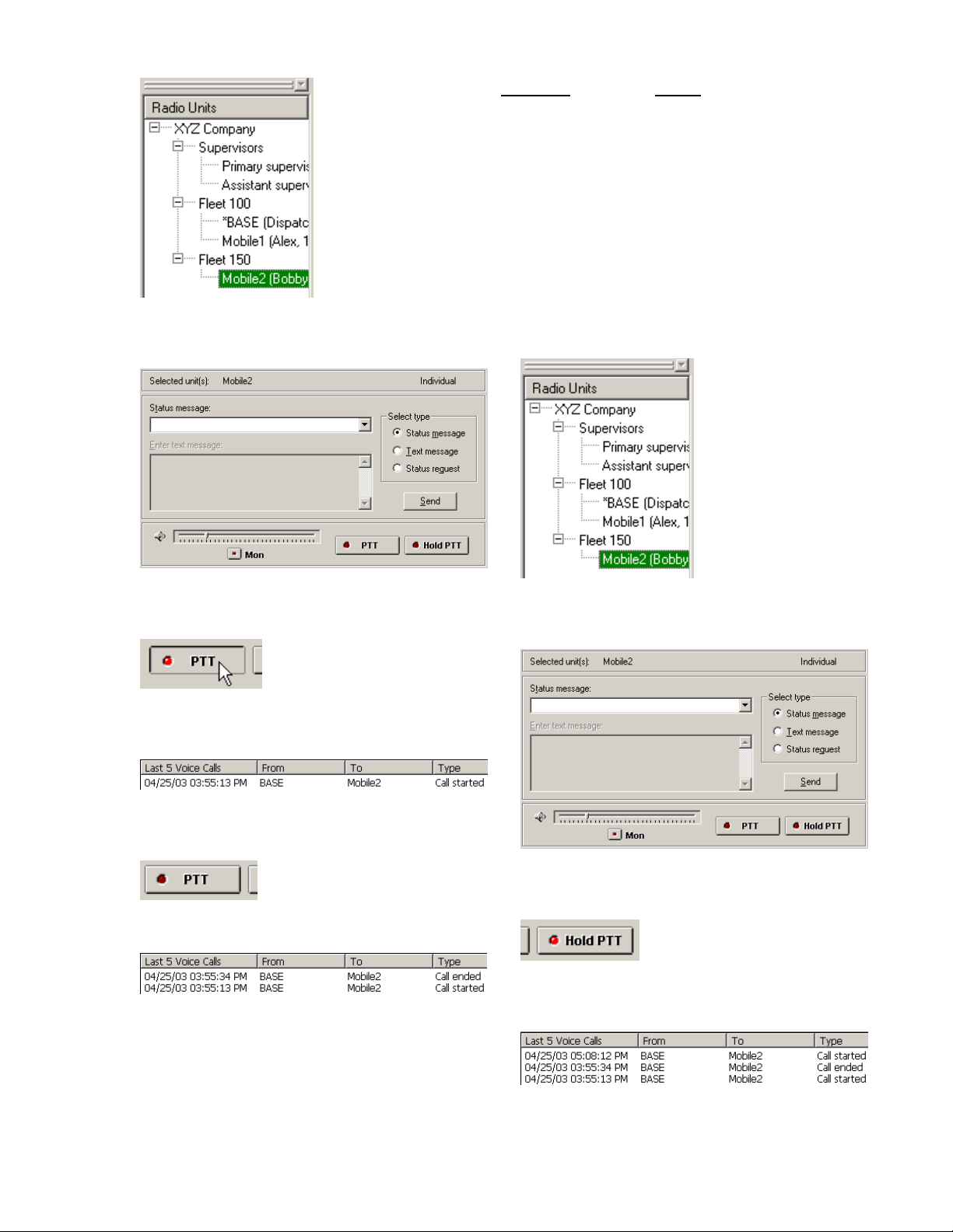
2. Notice the top of the Dispatch Control Panel
reflects the name of the selected radio.
Call Type
To broadcast System name root item
To call a group Fleet name item
To call a supervisor Supervisor sub-item
B. To make a call with Hold PTT pushbutton:
1. Select a call recipient by clicking on the
desired radio in the Radio Units docking
window.
Select
(e.g. XYZ Company)
(e.g. Fleet 150)
(e.g. Assistant supervisor)
3. Click and hold the PTT pushbutton, and talk
through the hand-mic.
Notice the Voice Call List displays the call you
just made.
4. When you are finish talking, release the PTT
pushbutton.
The Voice Call List indicates the call ended.
The example above illustrates the procedure for
calling an individual radio. To make a group,
broadcast, or supervisor call, do the following
when selecting a call recipient in the Radio Units
docking window:
2. Notice the top of the Dispatch Control Panel
reflects the name of the selected radio.
3. Click once on the Hold PTT pushbutton, and
talk through the hand-mic.
Notice the Voice Call List displays the call you
just made.
4. When you are finish talking, click once on the
Hold PTT pushbutton.
40
Page 41

The Voice Call List indicates the call ended.
5.13. Volume Control
To adjust the volume of the base radio, move the
slider along the slider bar. To move the slider,
you can do one of the following:
a) use the mouse to click and hold the slider,
and then drag it to the desired position.
Or,
b) click on either side of the slider.
Moving the slider towards the right end increases
the volume, while moving towards the left reduces
it.
Note: The Alarm Off menu item and its toolbar
button are available only when an emergency
message is received.
5.15. Launch Online Help
5.15.1. Using Context-sensitive Help
Button
The following example illustrates how to launch
the Help main screen to display information on
specific topic.
1. Click on the Context-sensitive Help button on
the toolbar invokes a special “Help mode”.
5.14. Turn Off Emergency Alert
When a radio in the field sends an emergency
message, FleetDispatchPRO generates an alarm
to inform the dispatcher of the event. To turn off
the alarm, do one of the following:
a) Click on the Alarm Off toolbar button.
b) Or, select the System menu, and then select
the Alarm Off menu item.
2. The mouse cursor turns into a Help cursor
(arrow + question mark).
3. Move the Help cursor to the area of the user
interface where you want to get help on (e.g.
Dispatch Control Panel) and click on it.
41
Page 42

4. The online Help main screen appears and
displays a topic that describes the selected
item.
You can use the same procedure to get help on
the other parts of the user interface.
5.15.2. Using Help Topics Menu Item
To launch the online Help:
1. Select Help menu, and select Help Topics
menu item.
2. The Help Topics dialog box appears. The
dialog box shows two types of items,
distinguished by the icons preceding the text
labels. The “paper with a question mark” icon
represents a help topic, while the book icon
contains a list of help topics.
Note: The label of the first button at the
bottom of the Help Topics dialog box changes
between Open and Display depending on
whether a book item or a help topic is
highlighted.
3. To see the list of help topics under a book
(e.g. Menus), click on the book and click on
the Open button. Notice the book icon opens
up and a list of topics displayed under the
book label.
4. To see a help topic (e.g. System menu) under
the book, click on the topic and click on
Display button.
5. The Help Topics dialog box closes up, and the
online Help main screen appears and displays
the selected topic.
42
Page 43

To open the Help Topics dialog box from the Help
main screen, click the Contents button near the
top of the Help main screen.
5.15.3. Green Underlined Help Links
The green underlined words that appear in help
topic screens are links to help topics that further
explain the green underlined words. When you
move the mouse cursor to pause over a link, the
mouse cursor turns into a hand cursor indicating
that it is right on top of the green text. Clicking on
the link takes you to the corresponding screen.
43
Page 44

6. Software Functions
6.1. Menus
FleetDispatchPRO’s Menu bar contains the
following menus:
• System menu
• Edit menu
• View menu
• Tools menu
• Help menu
Under each menu is a list of menu items, this is
where the user selects a command to carry out an
operation.
To see the menu items of a menu, move the
mouse pointer to the menu (for example, “System”
menu,) and click on it. A drop down list appears
and displays the menu items. When you move
the mouse cursor to hover over a menu item, the
menu item is highlighted, and the status bar at the
bottom of the main window displays more
information about the menu item.
Exit Exits FleetDispatchPRO
application.
The Alarm Off menu item is enabled only when an
Emergency message is received, the user can
then select the menu item to turn it off.
6.1.1.1. Configure Command
Use this command to turn on Configure mode.
When FleetDispatchPRO is in Configure mode,
select this command again will return it to Run
mode.
It is necessary to properly configure
FleetDispatchPRO for it to operate normally.
System configuration is allowed (and thus
Configure mode is available) only when
FleetDispatchPRO is not connected to the base
radio.
Selecting the Configure menu item will first cause
a password dialog to appear. After a correct
password is entered, FleetDispatchPRO switches
to Configure mode, and the user/administrator will
be able to access the User Administration, Define
Messages, and Settings views.
Shortcut
6.1.1. System Menu
Under System menu, the user can select the
following commands:
Configure Switches FleetDispatchPRO
between Configure mode and
Run mode.
Alarm Off Turns off computer’s audio and
visual alerts.
Connect Connects to base radio.
Disconnect Disconnects from base radio.
Toolbar
6.1.1.2. Alarm Off Command
Use this command to turn off the computer’s
audio and visual (status bar flashes in red) alerts.
When a radio in the field sends an emergency
message, FleetDispatchPRO generates an alarm
to inform the user of the event. To turn off the
alarm, select this command or the toolbar button
as shown below.
The Alarm Off command and its toolbar button are
available only when an emergency message is
received.
Toolbar
6.1.1.3. Connect Command
Use this command to connect to the base radio.
Shortcut
Page 45

The status bar displays the connection status of
the serial communication port.
Shortcut
Toolbar
6.1.1.4. Disconnect Command
Use this command to disconnect from the base
radio.
The status bar displays the connection status of
the serial communication port.
Toolbar
6.1.1.5. Exit Command
Use this command to end your FleetDispatchPRO
session. You can also use the Close command
on the application Control menu.
Mouse Double-click the application's
Shortcut
Shortcut
Control menu button.
Keys ALT+F4
6.1.2. Edit Menu
The Edit menu offers the following commands:
Undo Reverse previous editing operation.
Cut Deletes data from the text window
or the grid cell and moves it to the
clipboard.
Copy Copies data from the text window
or the grid cell to the clipboard.
Paste Pastes data from the clipboard into
the text window or the grid cell.
Delete Deletes data from the text window
of the Dispatch Control Panel; Or,
Deletes record(s) from Define Units
tab and Define Supervisors tab.
Select All Selects all data in the text window
of the Dispatch Control Panel.
Mark as
Unread
6.1.2.1. Undo Command
Use this command to reverse the last editing
action, if possible. The command is enabled or
disabled depending on what the last action was.
The Undo menu item is disabled (grayed-out) if
you cannot reverse your last action.
Toolbar
Keys CTRL+Z
6.1.2.2. Cut Command
Use this command to remove the currently
selected data from the text window of the
Dispatch Control Panel or from a grid cell and put
it on the clipboard. This command is unavailable
if there is no data currently selected.
Cutting data to the clipboard replaces the contents
previously stored there.
Toolbar
Keys CTRL+X
6.1.2.3. Copy Command
Use this command to copy selected data onto the
clipboard. This command is unavailable if there is
no data currently selected.
Copying data to the clipboard replaces the
contents previously stored there.
Toolbar
Keys CTRL+C
Marks incoming data messages as
unread.
Shortcut
Shortcut
Shortcut
45
Page 46

6.1.2.4. Paste Command 6.1.2.6. Select All Command
Use this command to insert a copy of the
clipboard contents at the insertion point. This
command is unavailable if the clipboard is empty.
Shortcut
Toolbar
Keys CTRL+V
6.1.2.5. Delete Command
This command works differently under different
situations:
a) Use this command to delete text characters
from the text window in the Dispatch Control
Panel. This command is unavailable if there is no
data in the text window;
or,
b) Use this command to delete one or more
selected records (rows) in a grid window. This
command applies only to the Define Units tab and
Define Supervisors tab.
Use this command to select all data in the text
window of the Dispatch Control Panel.
6.1.2.7. Mark as Unread Command
Use this command to mark received data
messages as unread. This command only applies
to received “data” messages, not voice call activity
messages. Data messages are displayed in the
Message List of the Message Dispatch view. An
unread message is shown in bold text.
To mark a received data message as unread,
click on a received data message that is shown in
regular text, and select Mark as Unread menu
item. The message will be displayed in bold text.
You can also achieve the same result by using the
pop-up menu. Use the right mouse button to click
on a received data message, a pop-up menu
appears and displays the Mark as Unread menu
item. Then, use the left-mouse button to click on
the Mark as Unread menu item, and the message
will be displayed in bold text.
To select a row, click on the row header cell of the
row to be deleted, the row will be highlighted in
black background and white text colors.
To select multiple rows, for example three rows,
click and hold the mouse button on the row
header cell of the first row to be deleted and move
the mouse cursor to the third row and release the
mouse button. Three rows will be highlighted.
When there is a row highlighted, the Delete menu
item is enabled. Selecting the Delete command
deletes the highlighted record.
Shortcut
Keys Del
6.1.3. View Menu
The View menu offers the following commands:
Message Dispatch
User Administration
Displays Message
Dispatch view.
Displays User
Administration view.
46
Page 47

Define Messages
Settings Displays Settings view.
Clear Messages
Recall Messages
Full Screen
Full Screen on
Startup
Toolbar Shows or hides the toolbar.
Status Bar Shows or hides the status bar.
The user/administrator can select to display one
of the views: Message Dispatch, User
Administration, Define Messages, or Settings. A
check mark appearing next to a menu item
indicates the menu item is selected and the
corresponding view is displayed.
Clear Messages and Recall Messages provide a
way to control how many messages to be
displayed in the Message List window.
Selecting Full Screen menu item causes
FleetDispatchPRO application to display
messages in full screen.
Full Screen on Startup menu item provides the
user an option of starting the application in full
screen.
The user can also toggle the Toolbar and Status
Bar on or off.
6.1.3.1. Message Dispatch View Command
Message Dispatch view integrates data
messaging capabilities and radio controls into an
all-in-one screen. Message Dispatch view is
actually a three-way split window that consists of:
• Message List
• Voice Call List
• Dispatch Control Panel
Displays Define
Message view.
Clears all items in the
Message List window.
Retrieves the last 100
messages from the
database.
Displays the Message List
window in full screen.
Specifies that next time starts
the program in full screen.
6.1.3.1.1. Message List
As the name suggests, Message List displays a
list of incoming and outgoing messages in
chronological order; the latest message is inserted
at the top. It also lists voice call activities that
have occurred in the field. The user/administrator
can configure FleetDispatchPRO to not display
voice call activities in the Message List by
selecting the proper option in the Settings view.
In any case, all messages are logged into a
message list database.
Outgoing messages are color coded with light
green pastel background, while incoming
messages are displayed with white background.
Unread incoming messages are displayed with
bold text font.
6.1.3.1.2. Voice Call List
Voice Call List was created specifically to allow
the user to monitor only voice call activities. Only
the last 5 voice calls are displayed.
6.1.3.1.3. Dispatch Control Panel
47
Page 48

Dispatch Control Panel actually consists of two
control sections:
• Data Messaging Control
• Voice Control
FleetSync™ data messaging is the key feature of
this computer aided dispatch system.
FleetSync™ messages include:
• Status messages
• Short text messages
• Long text messages
• Status request messages
With FleetDispatchPRO, the user can send and
receive Status, Short and Long messages.
Status request messages allow the user to
request status from radios in the field.
The Voice Control provides the user the
convenience of making voice calls through the
same panel.
The Mon button toggles the monitor function on or
off.
The PTT pushbutton on the panel works exactly
like the PTT button on the mobile radio hand-mic.
By using the mouse to click and hold the PTT
pushbutton, the user can talk through the handmic until the PTT pushbutton is released.
Hold PTT pushbutton provides the convenience
of not having to manually hold the PTT
pushbutton on the screen. Click on the Hold PTT
pushbutton works the same as push and hold the
PTT button on the hand-mic. Click on the Hold
PTT the second time will release the PTT.
Note: In the case of KMC-9C Base Station
Desktop Microphone, the user has to press the
PTT button on the Desktop Microphone to use the
microphone.
The slider bar is a volume control. Available
volume levels ranges from 0 to 31, and the default
level is 8.
6.1.3.2. User Administration View Command
User Administration view is where the
user/administrator sets up user and radio
information. Within this view are three tab
windows that divide the task into three stages:
Define Fleets Define radio fleets or
groups.
Define Units Define radio units to be
included in the available
fleets.
Define Supervisors Designate supervisors by
selecting from the
available supervisor IDs.
(Optional)
Each tab window contains a grid that organizes
information into rows and columns of data.
Please refer to section 3.8 General Usage of
Grid Window for more information on how to use
a grid window.
Any fleets, radio units, and supervisors defined in
User Administration view will be available as
message recipients or voice call recipients in the
Radio Units docking window.
6.1.3.2.1. Define Fleets Tab
Typically, a radio system setup begins from
creating new fleet groups. The Define Fleets tab
contains a grid that displays several columns of
fleet information.
The Fleet Number column lists fleet numbers that
are allowed (100 to 349) in the system. The Fleet
Number column is grayed out (disabled)
indicating they are not modifiable. To include a
fleet group in the system, look for a desired fleet
number (you may need to scroll down the grid,)
click on the cell to its right (under the Fleet Name
column) to make the cell active, enter a fleet
name (up to 20 characters), and check the
48
Page 49

corresponding checkbox under the Include
column. The Fleet Description field is optional;
the user can enter a description up to 25
characters.
As mentioned in the General Usage of Grid
Window section, the user has to click on a
different row to save the new changes.
Related topics:
• Section 3.8 General Usage of Grid Window
• Section 6.1.2.1 Undo Command
6.1.3.2.2. Define Units Tab
After the desired fleet groups have been defined
in the Define Fleets tab, the next step is to define
new radio units in the Define Units tab. Within
the Define Units tab is a grid that displays
columns of radio unit information. Among the
fields in each row, Fleet Number, Unit ID, and
Unit Name are required, the rest are optional.
Every radio unit is assigned to a fleet group;
therefore, a fleet number must be selected for
each radio unit. The cells in the Fleet Number
column are actually combo boxes that list all
allowable fleet numbers.
To see the fleet number list, click on a cell under
Fleet Number to make the cell active and a down
arrow button appears on the right end of the cell.
Click on the down arrow causes a dropdown table
to appear right below the active cell. As shown in
the figure above, the dropdown table lists exactly
the same information as that in the Define Fleets
tab. The user is able to select a fleet number from
the list for the active Fleet Number cell. Notice
that the fields under the Include column indicate
whether the corresponding fleet numbers are
included in the system. The user is allowed to
select fleet numbers that are not included in the
system, but only the included fleet groups are
available for selection in the Radio Units docking
window. After a fleet number is selected, the
dropdown table closes and the fleet number is
inserted into the active Fleet Number cell.
Next, click on the Unit ID cell in the same row and
enter an ID number; a valid Unit ID ranges from
1000 to 4999.
Then, click on the Unit Name cell in the same row
and enter a name for the radio unit; up to 20
characters are allowed.
The User Name (up to 20 characters) and the
Serial Number (up to 10 characters) are optional.
User Name field can be used to assign a person’s
name or job title to a radio unit. Serial Number
field is used to record the serial number on the
radio.
The checkboxes in the Long Message column
specify whether the corresponding radios are
allowed to receive long messages.
Note: You need to click on a different row to save
any changes.
Related topics:
• Section 3.8 General Usage of Grid Window
• Section 6.1.2.5 Delete Command
• Section 6.1.2.1 Undo Command
49
Page 50

6.1.3.2.3. Define Supervisors Tab
After fleet groups and radio units are defined, the
user/administrator is able designate certain radios
as supervisors. Define Supervisors tab contains
only two columns of data fields: Supervisor ID
and Supervisor Name.
Cells in the Supervisor ID column are combo
boxes that list Units IDs that the
user/administrator can specify as supervisor IDs.
Click on a cell in the Supervisor ID column
makes the cell active and a down arrow button
appears on the right end of the cell.
Click on the down arrow causes a dropdown table
to appear right below the active cell. The
dropdown table lists only unique Unit IDs defined
in the Define Units tab. Once an ID is selected,
click on the Supervisor Name cell in the same
row to enter a name for it.
Note: You need to click on a different row to save
any changes.
Related topics:
• Section 6.1.3.2.1 Define Fleets Tab
• Section 3.8 General Usage of Grid Window
• Section 6.1.2.5 Delete Command
• Section 6.1.2.1 Undo Command
6.1.3.3. Define Messages View Command
There are two types of messages the
user/administrator can predefine in the
FleetDispatchPRO application: FleetSync™ status
messages and predefined short messages.
6.1.3.3.1. Status Messages Tab
Status messages are messages that are
associated with the FleetSync™ status code
numbers. FleetSync™ status code ranges from
10 to 99, however, only status numbers 10 to 79
are user-definable, status numbers 80 to 99 are
special reserved code.
Status Messages tab lets the user/administrator
associate text messages with those code
numbers. To define a message, look for the
desired number in the Status Number column,
click on the Status Message cell in the same row
and enter a text message up to 25 characters.
Any status messages defined here will be
available in the Dispatch Control Panel.
The checkboxes in the Quick Status column
specify whether to include the corresponding
status messages in the Quick Status list in the
Shortcut docking window.
50
Page 51

To define a message, look for an empty cell in the
Predefined Message column, click on the cell,
and enter a text message up to 48 characters.
The user can also edit existing messages.
The checkboxes in the Quick Message column
specify whether to include the corresponding
predefined messages in the Quick Message list in
the Shortcut docking window.
Related topics:
• Section 3.8 General Usage of Grid Window
• Section 6.1.2.1 Undo Command
6.1.3.4. Settings View Command
Five of the special reserved code numbers are
available to the user; they are status numbers 88
to 92. These numbers already have messages
defined for them by the radio designers.
Related topics:
• Section 3.8 General Usage of Grid Window
• Section 6.1.2.1 Undo Command
6.1.3.3.2. Predefined Messages Tab
The user/administrator may need to send the
same messages to field radios from time to time,
the Predefined Messages tab provides a way of
creating canned messages. Predefined
messages are short text messages (maximum of
48 characters.)
Instead of repeating the same messages in the
Dispatch Control Panel, the user/administrator
can define short messages in this tab, and specify
to include them in the Quick Message list in the
Shortcut docking window. Messages that are
included are available for the user to select and
send to field radios.
Settings view consists of data fields used for
general settings of FleetDispatchPRO application.
Proper settings are required for
FleetDispatchPRO to function correctly.
51
Page 52

The user/administrator can select a serial
communication port in the Communication port
combo box for the connection between the PC
and the base radio.
Password Groupbox
Change Password button lets the
user/administrator change his/her password. To
switch FleetDispatchPRO from Run mode to
Configure mode, a password is required to
prevent any tampering of the system
configuration. Once FleetDispatchPRO is in
Configure mode, the user/administrator can
change the password in the Settings view by
clicking on the Change Password button.
During the process of configuring the system, the
user/administrator may have to repeatedly get into
Configure mode to set up the system and return to
Run mode to verify. For convenience, Skip
password for this session checkbox allows the
user/administrator to bypass the password
requirement. If the checkbox is checked, a
password is not required the next time the
user/administrator turns on Configure mode. As
the name suggests, password requirement is
skipped only for this session, which means that
after FleetDispatchPRO is closed, the next time it
is launched, a password is required to turn on
Configure mode.
After the user/administrator is satisfied with the
configuration, Skip password for this session
should be unchecked before exiting Configure
mode.
Radio Units Groupbox
System name field defines the root item label in
the Radio Units docking window. When the
System name is selected in the Radio Units
docking window, any messages sent out or voice
calls initiated by the dispatcher are broadcast to
all radios in the system
Base radio name combo box designates one of
the radios defined in the User Administration view
to be the base radio. A base radio is the radio
that is connected to the computer through a serial
cable.
Base radio model combo box indicates the
model name of the radio connected to the
computer.
Radio Units docking window lists all the active
radios defined in the User Administration view.
These radios are listed with one or more of the
following identifiers: unit name, user name, full ID,
and serial number. The user/administrator can
decide whether or not to display one or more of
these identifiers in the Radio Units docking
window by checking or unchecking the Unit
Name, User Name, Full ID, and Serial Number
checkboxes in the Settings view. If none is
specified, unit names of the radios will be
displayed by default.
Main identifier combo box specifies which
identifier is to be displayed first for each radio
listed in the Radio Units docking window.
Base radio response timeout Groupbox
Long message timeout specifies the maximum
amount of time FleetDispatchPRO will wait for a
response from the base radio after a long
message is sent, before FleetDispatchPRO
considers it as a failed attempt.
Similarly, Other message timeout specifies the
maximum amount of time FleetDispatchPRO will
wait for a response from the base radio after a
short message, a status message, or a status
request message is sent.
It is recommended that the Long message
timeout and Other message timeout be set to at
least 45 and 11 seconds, respectively.
Depending on the base radio configuration, the
user/administrator may adjust these values
accordingly.
Message List Groupbox
Display data messages only checkbox specifies
whether or not to display voice call activities in the
Message List window of the Message Dispatch
view.
The full path and file name of the currently active
message database are shown under the Display
data messages only checkbox. The
user/administrator can specify an alternate
database for logging messages by selecting the
New Name button or the User-specified…
button. The full path and file name of the newly
specified database will be shown accordingly.
If the user/administrator has specified a new
database name and decided to abandon it, he can
discard the new database name and revert to
52
Page 53

using the currently active database by selecting
the Use Current button.
All incoming and outgoing data messages and
voice call activities are saved in this database, up
to 1.5 million items. When that limit is reached,
the oldest message is deleted for every new
message logged, that is, first message in first
message out.
Message Alert Groupbox
The checkbox labeled Play an audible alert
when an emergency message arrives allows
you to enable or disable the audible portion of the
emergency signal that FleetDispatchPRO
generates. The display window below this
checkbox indicates the file name and location of
the wave file for this alert.
Similarly, the checkbox labeled Play an audible
alert when a new message arrives lets you
enable or disable the new message alert. The
wave file for this message alert is shown right
below the checkbox.
The Browse… button under each checkbox
allows the user/administrator to select an alternate
wave file for the corresponding message alert.
And clicking on the Use Current buttons will undo
the selections of the alternate wave files.
The emergency alert wave file is played
repeatedly until the user clicks on the “Alarm Off”
toolbar button; see 5.14 Turn Off Emergency
Alert.
The new message alert wave file is played once
each time a new message arrives.
Note that your computer must be equipped with a
sound card and it must be properly set up to play
wave files.
6.1.3.5. Clear Messages Command
Use this command to clear out all items displayed
in the Message List window.
If there is no item listed in the Message List
window, this command is disabled.
6.1.3.6. Recall Messages Command
Use this command to retrieve previous messages
from the database (100 at a time) and display
them in the message List window.
6.1.3.7. Full Screen Command
This command causes the Message List window
to display in the entire screen of the monitor. This
command is only available in Run mode.
6.1.3.8. Full Screen on Startup Command
This command is actually an option that allows the
user to specify how the Message List window is
displayed the next time the application is
launched.
A check mark appears next to the menu item
indicates the option is turned on. Without the
check mark, it is turned off. This command is only
available in Run mode.
6.1.3.9. Toolbar Command
Use this command to display or hide the Toolbar,
which includes buttons for some of the most
common commands in FleetDispatchPRO, such
as System Connect.
A check mark appears next to the menu item
when the Toolbar is displayed.
6.1.3.10. Status Bar Command
Use this command to display or hide the Status
Bar, which describes the action to be executed by
a selected menu item or depressed toolbar button.
A check mark appears next to the menu item
when the Status Bar is displayed.
53
Page 54

6.1.4. Tools Menu
6.1.4.1. Export… Command
Help Topics Offers you an index to topics on
which you can get help.
About Displays the version number of
this application.
6.1.5.1. Help Topics Command
Use this command to display the Help Topics
dialog box:
Use this command to invoke the Export dialog
box, which is an export messages utility. This
utility allows the user to export messages from a
database to a Comma Separated Values (CSV)
file.
The Export dialog box provides some flexibility in
allowing the user to select a database for
exporting messages, to specify a preferred name
for the CSV file, and to limit the amount of
messages exported using a set of criteria.
The CSV files are created with a naming
convention that ensures unique file names; for
example, a file name,
Msg20031015_162118.csv,
indicates that the file was created on October 15
2003, at 4:21:18 PM. The military format is
adopted for the time portion of the name. By
default, the CSV files are stored in the same
directory where FleetDispatchPRO is installed,
unless the user has selected a different one. The
user may open the CSV files with any software
that accepts CSV format (e.g. Microsoft Excel) or
with a text editor.
th
6.1.5. Help Menu
The Help menu offers the following commands,
which provide you assistance with this application:
From the Help Topics dialog box, you can jump to
instructions for using FleetDispatchPRO and
various types of reference information.
The help information on specific topic is displayed
in an online Help main screen. To return to the
Help Topics dialog box from the Help main
screen, click the Contents button on the Help
main screen.
,
6.2. Toolbar
The toolbar is displayed across the top of the
main window, right below the menu bar. The
toolbar provides a quick access to a number of
the menu item commands in FleetDispatchPRO.
When the mouse cursor pauses over a toolbar
button, a small ToolTip window displaying the
button’s command appears near the mouse
54
Page 55

pointer, and the status bar displays more
information about the toolbar button.
To hide or display the Toolbar, select Toolbar
command on the View menu, or press the key
combinations: Alt+V and then Alt+T.
6.2.1. Toolbar Buttons
The following table lists the functions of the
buttons:
Click To
Configure FleetDispatchPRO application.
Turn off FleetDispatchPRO emergency
alarm. See Alarm Off command.
Connect to the base radio.
Disconnect from the base radio.
6.2.2. Connect/Disconnect Base Radio
To connect to the base radio, click on the Connect
button
Disconnect button
disconnection from the base radio. While
connected, the Configure button
indicating that system configuration is not allowed.
. Once a connection is made, the
is enabled to allow
is disabled,
6.2.3. Configure FleetDispatchPRO
While not connected to the base radio, the
user/administrator is able to configure the system
by clicking the Configure button
the Configure button will first cause a password
dialog to appear, after a proper password is
entered, FleetDispatchPRO switches to Configure
mode, and the user/administrator will be able to
access the User Administration, Define
Messages, and Settings views.
. Selecting
Remove selected data and store it on the
clipboard.
Copy the selection to the clipboard.
Insert the contents of the clipboard at the
insertion point.
Reverse the last editing. Note: You
cannot undo some actions.
Context Help button.
When FleetDispatchPRO is launched, it is
executing in Run mode. In Run mode, only the
Configure button
are enabled, all other buttons are disabled
(grayed out.) This means that the user can either
configure the software or connect to the base
radio.
Note: If this is the first time FleetDispatchPRO is
launched, it is necessary to configure the software
before you attempt to connect to the base radio.
and Connect button
6.3. Status Bar
The status bar is displayed at the bottom of the
FleetDispatchPRO window. To display or hide the
status bar, select the Status Bar command on the
View menu.
The left section of the status bar displays status
and error messages. In addition, this section
shows messages that describe the functions of
menu items as you use the arrow keys to navigate
through menus. This section also shows
messages that describe the functions of toolbar
buttons as the mouse cursor pauses over those
toolbar buttons.
The sections on the right provide visual indication
of the connection status of the serial
communication port.
When FleetDispatchPRO is not connected to the
base radio, the red “connectors” indicator is
shown as separated.
55
Page 56

While making an attempt to connect, the
“connectors” indicator is shown as above.
When connected, the “connectors” are joined and
they turn into green color.
When in Configure mode, the text indicator
displays “Configure”. You can only configure the
software when it is not connected to a base radio.
The Tx and Rx LED lights simulates activities
happening at the serial communication port; it
provides visual indication of data transmission
between the PC and the base radio.
6.4. Shortcut Docking Window
The Shortcut docking window contains three
shortcut lists:
• Select View shortcut buttons
• Quick Status message list
• Quick Message list (predefined short text
messages)
This shortcut list contains a list of buttons that
provide a quick access to a desired view, instead
of selecting a command on the View menu.
In Run mode, only the Message Dispatch button
is accessible. In Configure mode, the
user/administrator is allowed to select between
Message Dispatch, User Administration, Define
Messages, and Settings views by clicking on the
corresponding buttons. However, the Message
Dispatch view is disabled in Configure mode.
6.4.2. Quick Status Message List
6.4.1. Select View Shortcut Buttons
The Quick Status message list contains a list of
FleetSync™ status messages that the user can
select to send to a mobile radio. The purpose of
this list is to provide the user an easy access to a
short list of most frequently used status
messages. The user can specify which of the 75
(70 user-defined and 5 special reserved) status
messages defined in the Define Messages view
are to be included in this Quick Status list. If
desired, all status messages can be included.
The numbers enclosed in the parentheses at the
end of each messages are FleetSync™ status
code numbers that are associated with the
defined messages.
56
Page 57

6.4.3. Quick Message List
The Quick Message list lets the user send most
frequently used predefined short messages
without having to repeat typing the same
messages. The user can specify which of the 100
predefined short messages in the Define
Messages view are to be included in this list. If
desired, all short messages can be included.
6.5. Radio Unit Docking Window
item can have a list of radio unit sub-items
associated with it. By double-clicking a fleet
group item, the user can expand or collapse the
associated list of radio unit sub-items. The same
can also be done by clicking the square boxes
with a + or - sign preceding the fleet group items.
The “Supervisors” item is a special case, it does
not represent a fleet group. It contains a list of
supervisor sub-items defined in the User
Administration view. The “Supervisors” item
exists only if the user/administrator defined at
least one supervisor.
Fleet group items and their radio unit sub-items
are defined in the User Administration view.
FleetDispatchPRO supports up to 4000
FleetSync™ IDs.
When an item in the Radio Units docking window
is selected, the Dispatch Control Panel shows the
selected unit and indicates the type of the call,
that is, the panel indicates whether the
FleetDispatchPRO user has selected an
individual, a group, a broadcast, or a supervisor
call target. Call types are determined as the
following:
Selected Item
System name root item Broadcast
Fleet group item Group
Supervisor sub-item Supervisor
Radio unit sub-item Individual
Call Type
The Radio Units docking window displays a
hierarchical list of items, which provides a clear
view of the organizational structure of the radio
system. The tree items represent voice call or
message receivers; a receiver can be an
individual radio user, a fleet group, or the entire
system. The FleetDispatchPRO user (e.g. a
dispatcher) has to select a receiver in order to
make a call or send a message.
At the root of the tree structure is a user-definable
system name, e.g. Kenwood, or Sunshine Cab
Company. (System name is defined in the
Settings view.)
Under the system name root item is a list of items
that represent fleet groups (e.g. you can define
them as Fleet 100, Warehouse, etc.), with the
exception of “Supervisors” item. Each fleet group
57
Page 58

7. Troubleshooting
Security Key Not Found
Make sure the hardware key is attached to the
parallel/printer port of your computer. The parallel
port is a 25-pin connector typically located in the
back panel of the computer.
Communication Link Not Established
Before you send a message or make a call, you
need to electronically connect to the base radio.
See section 5.3 Connect to Base Radio.
No Response From Base Radio
Error Message:
“COM# received no response from base radio,
please make sure it is connected and powered
on.”
where # = serial port number you have selected in
the Settings view.
Possible causes:
1) The base radio is not plugged in to the serial
port of the computer.
2) The base radio is not powered on.
3) The base radio is plugged in to another serial
port of the computer. For example, you
selected serial port 1 in Settings view, but you
plugged in the base radio serial cable to serial
port 2 of your computer.
4) Base radio response timeout is too short.
Increase the timeout value for the Other
message timeout field or Long message
timeout field in the Settings view, depending
on what type of message you are sending that
causes the error message.
If the message appears when you are trying
to connect to the base radio and the other
possible causes do not apply, then increase
the Other message timeout value.
See section 4.4.8 Adjust Response
Timeout.
Cannot Hear Message Alert
Possible causes:
1) The speakers are not plugged in to the sound
card.
2) The speakers are not powered on.
3) The speakers’ volume is not turned up.
4) There is no sound card installed on the
computer.
5) The sound card is muted by the Volume
Control applet.
6) The wave files selected in the Settings View
have been removed.
7) The audio driver is not installed.
 Loading...