

Kenwood DV-705, DVFR-5070-S Service manual
70%
MULTIPLE DVD/VCD/CD PLAYER
12345
DISC SKIP SEQ.MODE
POWER
-ON –OFF
AV
DV-705/DVF-R5070-S
SERVICE MANUAL
© 2003-6 PRINTED IN KOREA
B51-5860-00 (K/K) 1356
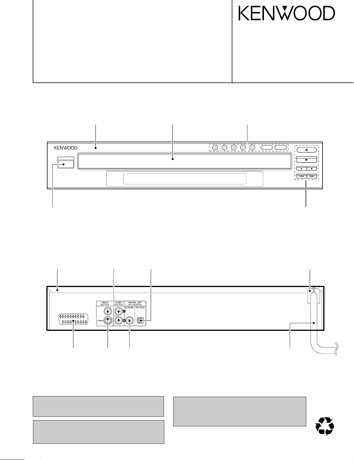
Knob
(K27-2508-08)
Top cover *
(A01-)
Cabinet panel *
(A60-)
Phono socket
(E63-1227-08)
Optical out
(GP1F32T)
Crystal Window *
(B03-)
Button ass’y
(K29-8327-08)
Button
(K29-8328-05)
AC power cord bushing
(J42-0350-08)
Scart dual *
(E40-)
In compliance with Federal Regulations, following are reproduction of labels on, or inside the product relating to laser
product safety.
DIN socket
(E68-0018-08)
Caution : No connection of ground line if disassemble
the unit. Please connect the ground line on
rear panel, PCBs, Chassis and some others.
Phono socket
(E63-1244-08)
AC power cord *
(E30-)
* Refer to parts list on page 15.
KENWOOD Corp. certifies this equipment conforms to DHHS
Regulations No.21 CFR 1040. 10, Chapter 1, subchapter J.
DANGER : Laser radiation when open and interlock defeated.
AVOID DIRECT EXPOSURE TO BEAM.
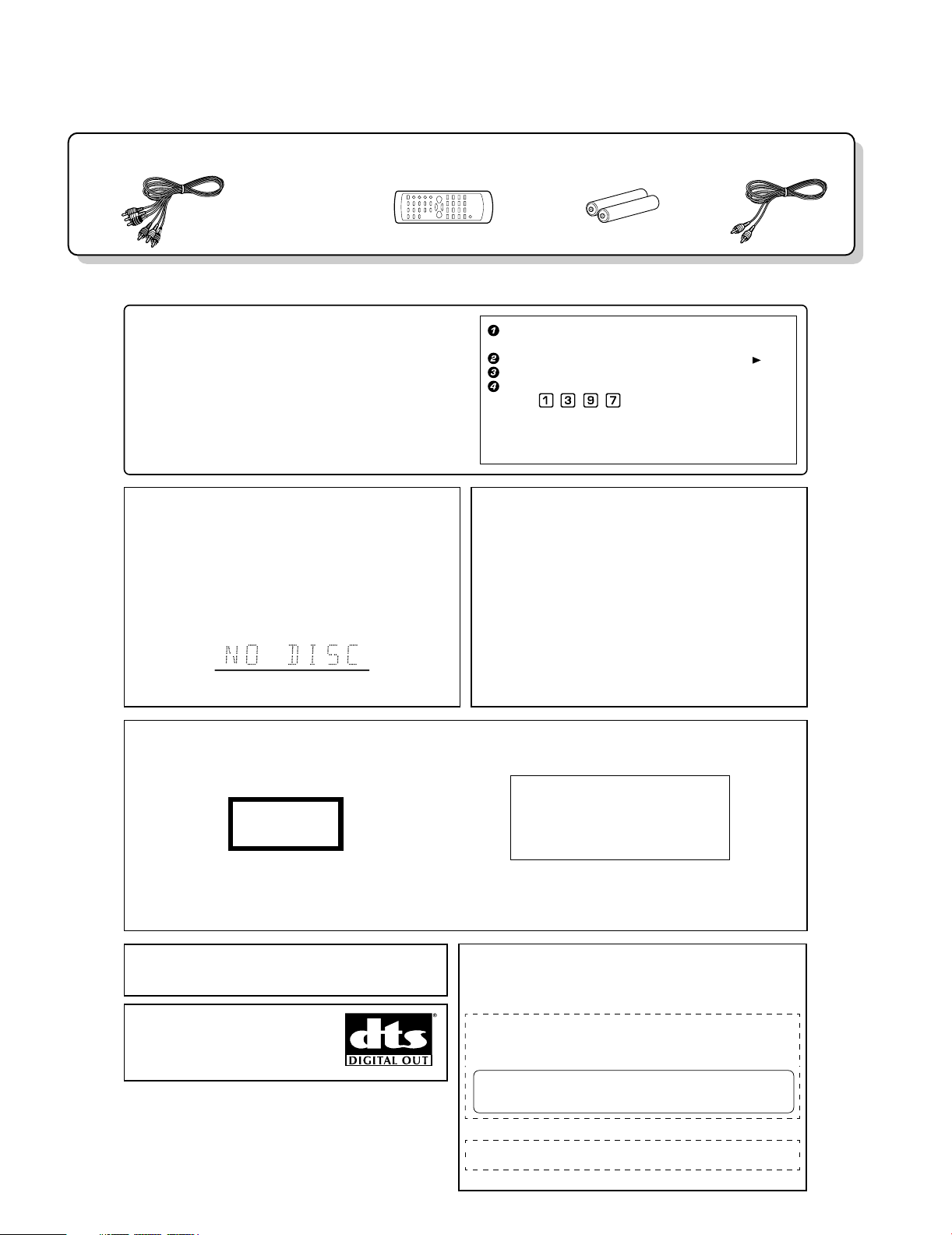
Batteries(R6/AA) ...(2)
Audio video cord (Red, White, Yellow) ...(1)
(E30-2990-08)
Remote control unit ...(1)
(A70-1570-08)
Coaxial cable ...(1)
(E30-7235-08)
DV-705/DVF-R5070-S
Caution on condensation
Before transporting or moving this unit, carry out the
following operations.
1. Set the POWER ON/OFF switch to the ON
without loading a disc.
2. Wait a few seconds and verify that the display
shown appears.
3. Set the POWER ON/OFF switch to OFF.
Note related to transportation and movement
Condensation (of dew) may occur inside the unit when there is a great
difference in temperature between this unit and the outside. This unit
may not function properly if condensation occurs. In this case, leave
the unit for a few hours and restart the operation after the condensa-
tion has dried up.
Be specially cautious against condensation in the following circum-
stances:
When this unit is carried from one place to another across a large
difference in temperature, when the humidity in the room where
this unit is installed increases, etc.
"DTS" and "DTS Digital Out" are trademarks of Digital Theater Systems, Inc.
Manufactured under license from Dolby Laboratories.
"Dolby" and the double-D symbol are trademarks of Dolby
Laboratories.
The marking of products using lasers
(For countries other than U.S.A. and U.S.-Military)
Inside this laser product, a laser diode classified as Class 2 laser radiation is contained as alerted by the internal caution label shown above. Do
not stare into beam or view directly with optical instruments.
Location: DVD laser pick-up unit cover inside this product
CAUTION
VISIBLE AND INVISIBLE LASER RADIATION
WHEN OPEN. DO NOT STARE INTO THE BEAM OR
VIEW DIRECTLY WITH OPTICAL INSTRUMENTS.
DO NOT PRESS ON THIS SURFACE
The marking this product has been classified as Class 1. It
means that there is no danger of hazardous radiation outside
the product.
Location: Back panel
CLASS 1
LASER PRODUCT
Operation to reset
During stop mode, press the MENU key on the remote to
enter "Control Panel" menu.
Select the "System" icon, then press the Cursor right ( ) key.
Select "Restore Setup Info".
Press the numeric keys as shown below.
Press
, , , , then press the ENTER key.
When resetting is done according to this method, all settings,
including the settings for password and parental level, will be
reset to the factory defaults.
The microprocessor may fall into malfunction (impossibility to operate erroneous display, etc.) when the
power cord is unplugged while power is ON or due to
an external factor.
In this case, switch off the power, wait for several seconds, and then switch the power on again.
Return to the factory defaults by resetting the micropro-
cessor is done as shown as follows.
CAUTION:
Use of controls or adjustments or performance of procedures other than
those specified herein may result in hazardous radiation exposure.
In compliance with Federal Regulations, the following are reproductions
of labels on, or inside the product relating to laser product safety.
KENWOOD CORPORATION
2967-3, ISHIKAWA-CHO,
HACHIOJI-SHI,
TOKYO, JAPAN
KENWOOD CORP. CERTIFIES THIS EQUIPMENT
CONFORMS TO DHHS REGULATIONS NO. 21 CFR
1040.10, CHAPTER 1, SUBCHAPTER J.
Location: Back Panel
CAUTION- LASER RADIATION WHEN OPEN.
DO NOT STARE INTO BEAM.
Location: Laser Pick-up Unit Cover inside this product
ACCESSORIES / CAUTIONS
Accessories
Cautions
2
DV-705/DVF-R5070-S
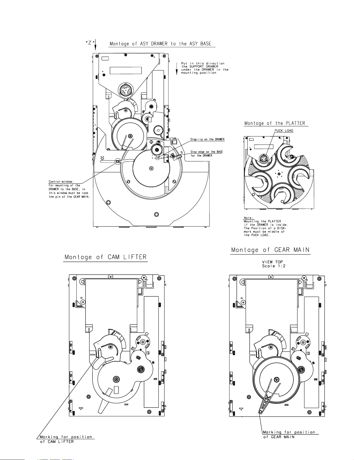
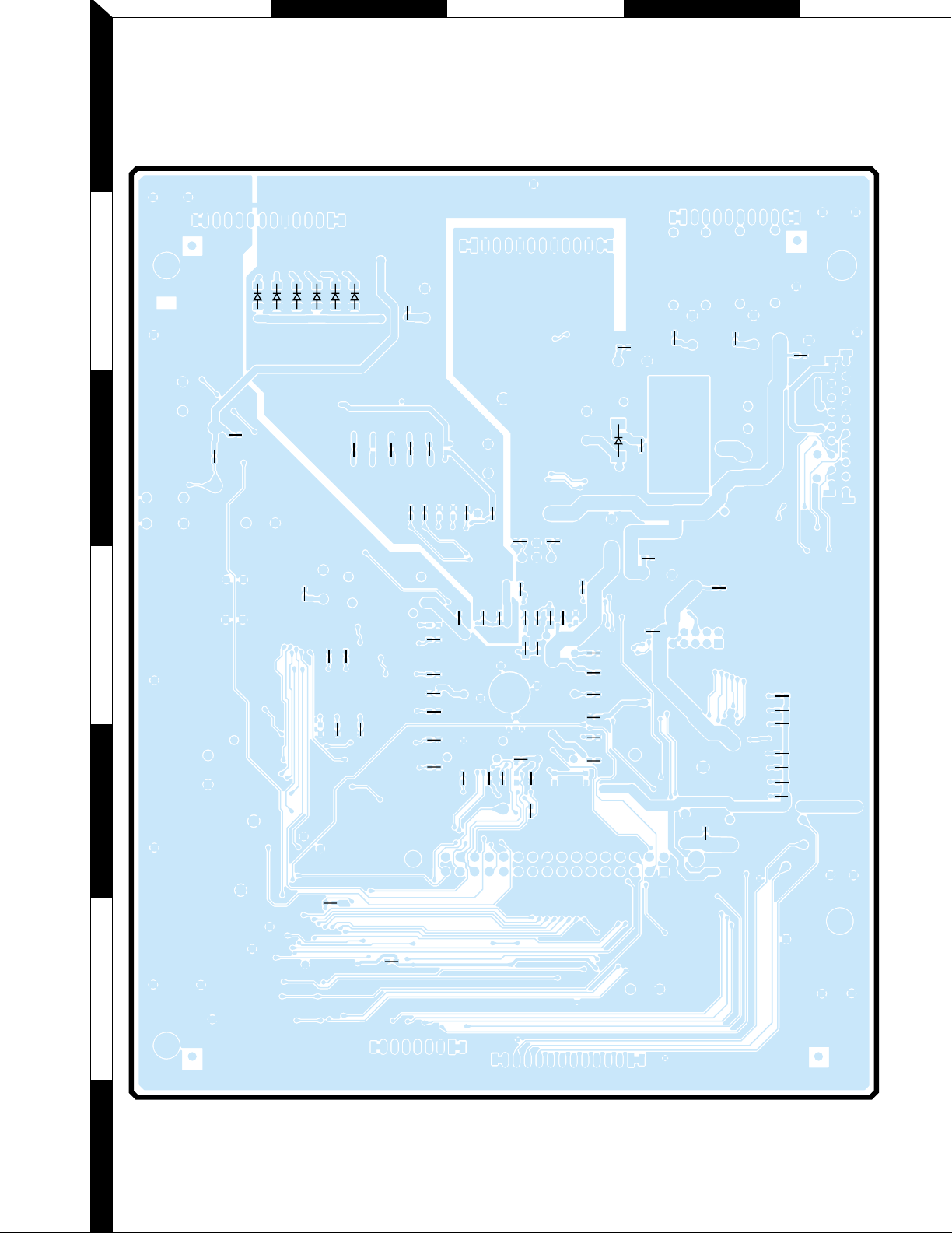
ASSEMBLY FOR REPAIR
3
A BDCE
C12
L71
L70
L69
L68
C2
C4
C6
C22 C9
C11
R89
CD3
R63
L78
L77
R68
R70
R73
R75
R77
GP4
GP1
R78
R12
R2
GP3
TP6
L12
L15
C90
R56
R53
C47
R65
L25
X1
GP2
R66
R57
L60
R55
L61
R54
L62
R58
R61
R60
L63
L64
L65
L66
L67
R13
R14
R15
R17
R18
R19
R20
C93
TP5
R76
R74
R72
R69
R71
L46
L40
L35
L37
C17
C15
C14
C72
L36
R46
R44
R43
R42
R41
R40
R50
R38
L47
L48
L49
L50
L45
L43
L1
L11
L19
L26
L28
L38
L18
L14L82
R1
L44
C13
R16
R23
R26
R28
R32
L53
C37
L2
L13
L20
L29
L39
C18
R10
C65
R21
R24
R30
R33
L42
R47
R48
C98
C81
C97
C96
C87
C88
C89
C82
R79
R81
R83
R80
R82
R84
R85
C73
C74
R62
R64
R67
R112
L16
L79
L3L4L5L6L7L8L9
L10
L80
L75
L73
L74
L81
C92
R36
R37
L17
I
G
O
1
1
7
14
8
152
156 105
104
53
157
208
1
124
48 25
110
2011
1
1
17
12
1
2
31
32
10
2011
110
2011
43
86 44
112
1
2
1
1
112
10
18
19
2
9
10
4
85
MAIN POWER
FRONT PANEL
J5
AUDIO SIGNAL
MAIN UNIT (SIDE-A)
J6
U6
LOARDER CONNECTOR
CONTROL BDARD
+9V
+5V
J8
U3
/FLASH CS
R/W
J9
U9
U4
U7
U8
U5
J11
J12
U11
J2
U2
D15
S1
VIDEO SIGNAL
J1
D1
D3
D5
D7
D10
D12
BE
Q1
BEQ2BEQ3BE
Q4
BE
Q5
BE
Q6
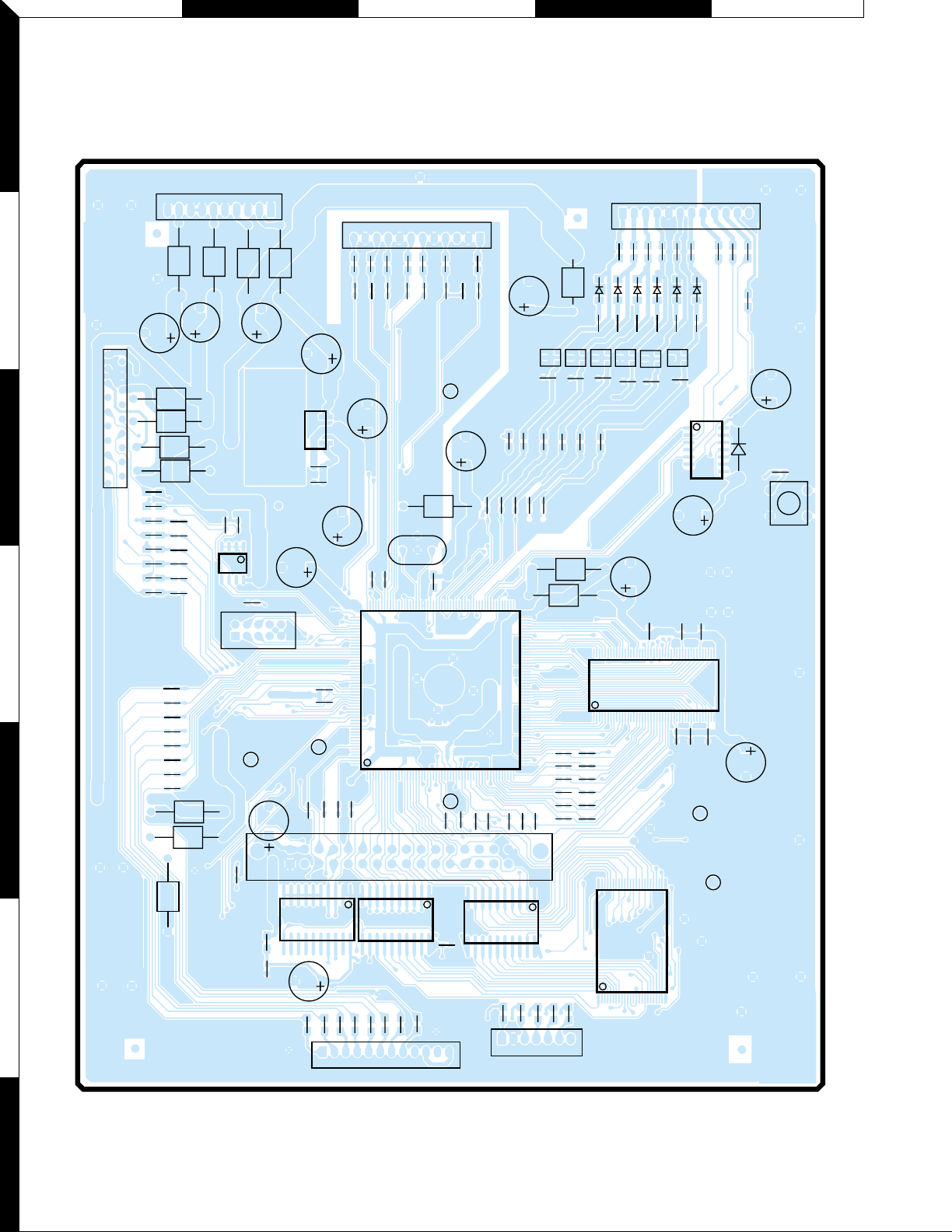
PC BOARD
1
2
3
4
5
6
7
4
Refer to the schematic diagram for the value of resistors and capacitors.
PC BOARD
C19
C10
C8
C5
C3
C1
C7
R87
R34
R31
R25
R22
R11
R27
C40
R35
C70
C21
C23
C51
C39
C38
R45
C42
L51
C71
C52
L52
C43
C54
C53
C67
R86
C50
C35
C34
C75
R88
C101
C99
C100
C86
C85
C84
CX3
C25
C24
C28
C44
R3
R4
R5
R6
R7
R8
R9
C45
C20
C27
C60
C59
C58
C66
C57
C56
C55
C91
C102
C33
C69
C48
C46
C36
C68
R600
D13
D11
D8D6D4
D2
D14
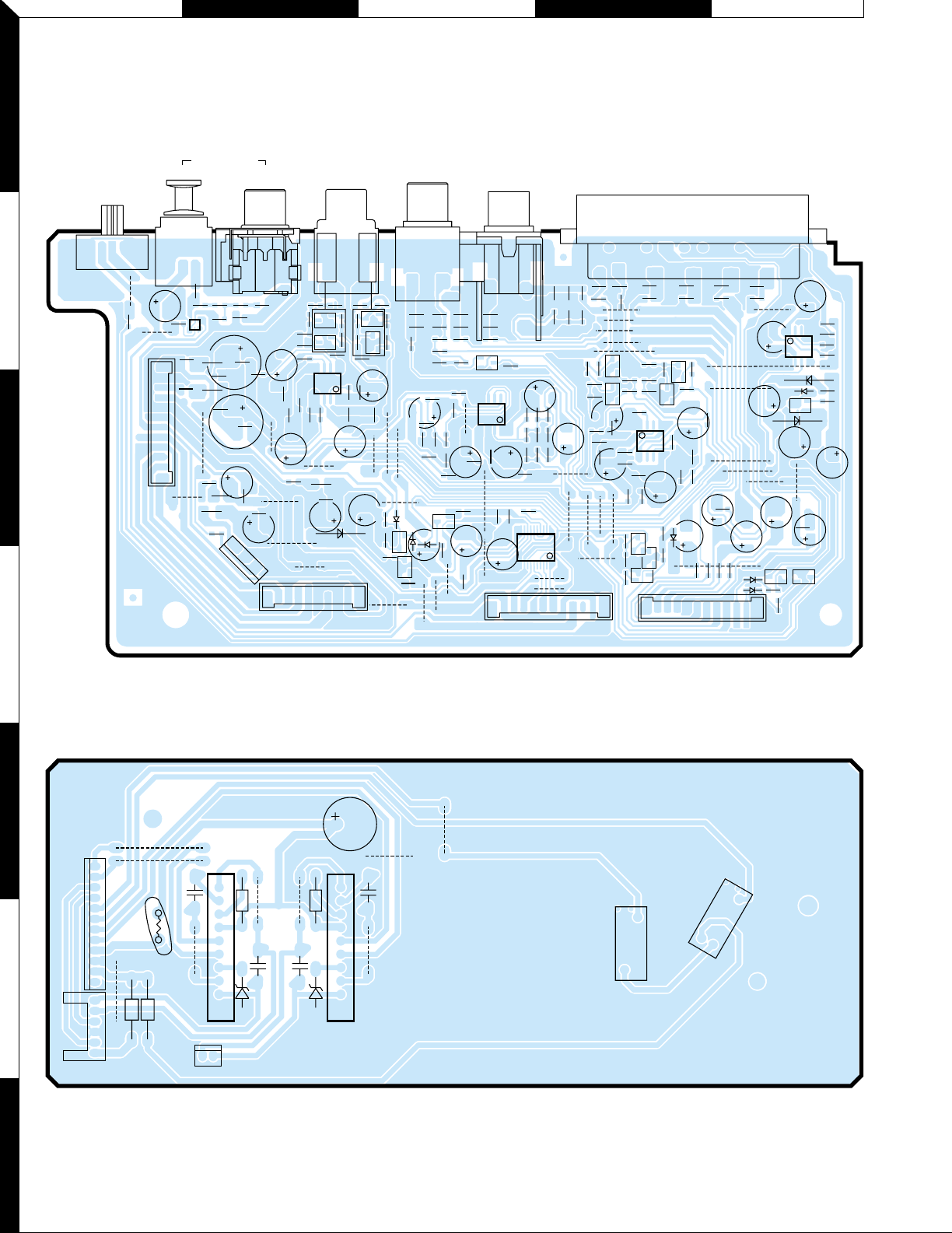
MAIN UNIT (SIDE-B)
1
2
FHJGI
3
4
5
6
7
Refer to the schematic diagram for the value of resistors and capacitors.
5
K LNMO
L302
L305
L303
L301
L306
R318
R323
R324
R325
C322
R316
C321
R315
C320
R314
C319
R307
C308
C309
R312
C302
R344
R305
C306
R348
R301
R346
C304
R347
R407
R415
C332
R408
R405
R414
R406
B300R342
C324
R331
R332
R353
R396
R397
R399
R419
C388
C389
R400
C336
R357
C339
R418
R417
C325
L308L307
LR
C305
R302
C307
R308
R382
R381
R391
C384
C374
R362
R359
R369
R371
C351
R373
C352
R420
R377
R380
R394
R412
R317
R366
R310
R339
R341
R360
R337
R336
R340
R372
R421
R311
C317
R313
R304
R343
C303
R345
C301
R306
R303
R354
R358
R411
R410
R355
R409
C328
C330
C337
R404
C333
R401
R402
C331
C378
R383
C373
R384
R392
C375
C380
R349
R374
C361
R370
C353
R351
R326
R327
R329
R330
R328
R309
R365
R364
R367
R368
R350
R378
R379
R413
R416
C370
R398
C360
C350
R335
R338
R361
R334
R386
R387
R385
C379
R388
C383
R390
R389
R403
C329
R333
GND
VCC
OUT
R352
R356
R422
R423
14
85
EB
EB
EB
EBEB
EB
EB
EB
EB
EB
EB
EB
EB
EB
EB
EB
EB
EB
14
85
58
41
11 20
10 1
58
41
13
54
C323
JMP17
C390
1
10 1
11
121
220
1212
I
G
O
12
C340
JMP41
JMP38
JMP18
JMP26
JMP33
JMP12
JMP31
JMP37
JMP32
JMP13
JMP22
JMP34
JMP15
JMP35
JMP14
JMP16
JMP28
C391
JMP27
C334
JMP23
JMP4
C338
JMP21
JMP36
JMP3
C385
JMP29
C376
C377
C381
C392
JMP24
C372
C369
JMP2
JMP1
JMP11
C396
C362
C363
C364
C395
C318
C311
C349
JMP9
JMP40
JMP6
JMP5
JMP25
JMP30
C315
C314
JMP8
JMP20
C348
C397
C393
C394
JMP39
JMP19
JMP7
JMP10
C371
C335
C341
C327
C326
C382
D302
D301
D303
D304
Q303
Q310
D310
D309
Q318
Q301
Q315
Q316
Q311
Q308
Q307
Q309
Q314
Q304
Q317
Q312
Q302
Q313
Q305
Q306
I301
I303
I305
I304
I306
I300
D308
S301
AV OUT UNIT
COMPONENT
VIDEO
OUTPUT
VIDEO
OUTPUT
AUDIO
OUTPUT
COAXIALOPTICAL
DIGITAL OUT
COMPONENT
VIDEO
OUTPUT
N311
K302
K301
K306
K305
K304
K303
D306
D307
N312
N314
N313
I307
D305
R003
C001
JW04
C002
C003
JW10
C004
JW09
JW03
R001
R002
JW05
JW06
R004
JW01
JW02
1
12
1
6
21
1
10
1
10
L001
JW07
PI01
PI02
C005
P001
P027
P002
IC01
MECHA CONTROL UNIT
IC02
D001
D002
PC BOARD
1
2
3
4
5
6
7
6
Refer to the schematic diagram for the value of resistors and capacitors.
 Loading...